
Age Estimation of a Hybrid Energy Storage System for Vehicular Start–Stop †

1
College of Engineering, West Texas A&M University, Canyon, TX 79016, USA
2
College of Engineering and Computing, University of South Carolina, Columbia, SC 29208, USA
*
Author to whom correspondence should be addressed.
†
This paper is an extended version of our paper published in the 2015 IEEE Energy Conversion Congress and Exposition conference (ECCE), Montreal, QC, Canada, 20–24 September 2015; pp. 6199–6205.
Energies 2023, 16(2), 623; https://0-doi-org.brum.beds.ac.uk/10.3390/en16020623
Submission received: 30 November 2022
/
Revised: 19 December 2022
/
Accepted: 27 December 2022
/
Published: 4 January 2023
(This article belongs to the Special Issue Planning, Operation and Control of Renewable Energy Sources and Energy Storage Devices Assisted Hybrid Power System)
Abstract
:Ultracapacitors are energy storage devices that have shown outstanding capability in a vast spectrum of applications, mainly in energy storage systems required to deliver short bursts of electrical energy. Ultracapacitors possess high power density while batteries possess high energy density. In this paper, a hybrid energy storage device comprising a lithium-ion ultracapacitor module and a lead acid battery was modeled, built, and tested for vehicular start–stop application, which requires a much larger number of engine cranking events than conventional vehicles. The combination of a lead acid battery with Li-ion ultracapacitors was chosen due to the fact that the vast majority of vehicles utilize lead acid batteries to crank the internal combustion engine. This allows retrofitting this hybrid setup in conventional vehicles along with the start–stop feature without inflicting damage to the already installed lead acid battery. The start–stop feature puts high stress on the lead acid battery, contributing to its faster aging. This feature is commonly found in hybrid vehicles to save the unnecessarily burned fuel during idling. This paper discusses aging of the lead acid battery as a result of being used in hybrid vehicles equipped with start–stop when used alone versus when used in the hybrid setup. The paper shows cranking tests performed on a number of cars to obtain voltage, current, power, and energy requirements for combustion engine cranking. Mathematical derivation, analysis, and an energy storage age estimation method are also presented. A set of cranking events followed by capacity checks performed on two automobile energy storage systems, one being a lead acid battery alone and the other being the proposed hybrid module, show the advantage of integrating the ultracapacitor module with the lead acid battery to extend its life span almost fivefold in a hybrid automobile.
1. Introduction
A hybrid energy storage system (ESS) made up of a lead acid battery and an ultracapacitor module [1,2] is modeled, simulated, built, tested, and presented in this paper. This ESS can replace lead acid batteries found in conventional vehicles in order to integrate the start–stop feature aiming to improve the mile-per-gallon (mpg) rating without shortening the life span of lead acid batteries through extreme repetitive engine cranking that the start–stop application introduces.
Ultracapacitors are power-dense devices that have been considered for electric and hybrid vehicles for numerous advantages. The authors of [3,4,5] discussed the advantages of ultracapacitor use in propulsion systems to meet peak power demands. Integration of lead acid batteries with ultracapacitors for vehicular applications has been discussed in simulations and experiments [6,7,8]. Control schemes have also been discussed for ultracapacitors [9,10,11]. The long-term increase in demand for oil and gas stimulates the need for highly efficient systems that run on fossil fuels. Most existing automobiles, being among the major systems running on gas, can benefit from the addition of an application that assures the efficient consumption of gas by burning gas only when the internal combustion engine is in use. When idling, the application automatically switches off the engine to save gas. The engine is then switched back on when the gas pedal is pressed. Such an application is called start–stop. This technology has been used in East Asia and Europe for two decades to save gas and reduce greenhouse emissions into the atmosphere. However, the main energy storage system used was an enlarged lead acid battery or two parallel lead acid batteries. This is used to reduce the stress that frequent engine cranking imposes on the battery as a direct result of using the start–stop technology. In a study conducted by Toyota on Tokyo traffic in the late 1970s, gas savings of up to 10% were achieved using this technology. Studies conducted by numerous automobile manufacturers showed significant gas savings, while suggestions have continually been made to further improve the technology. Transitioning toward carbon-neutral technologies via electrification and hydrogenation has been the trend in recent decades [12]. The start–stop feature implemented in hybrid vehicles falls into the electrification category.
In engine cranking applications, several factors are taken into account to determine how successful a starter can be considered. These factors include cranking time, cranking torque, time to reach the desired speed, and the current/voltage variations that are observed across the energy storage device [13,14,15,16]. The last factor is of particular interest in this work as discussed in more detail in the later sections.
Start–stop applications and starter–alternator systems have been researched, and many papers have been published in the field. In [17], a control system was proposed for an integrated starter alternator (ISA) where the battery is managed by controlling the active power of the ISA.
The authors of [18] presented a more sophisticated approach. A bidirectional converter for the integrated starter/alternator system was proposed. A buck-boost converter was used to charge/discharge the battery, and a VSI was used to connect to the DC machine. The authors of both [17,18] showed similar results in the response time of cranking/starting the engine. These papers lacked what the topology in this work proposes: adding a lithium-ion capacitor in parallel to the battery to help supply the demanded cranking current as the engine starts. This reduces the stresses on the battery and can help in extending its lifetime [19]. Furthermore, it allows greater effective discharge capacity [20,21]. The idea of coupling supercapacitors with cells is not new and has been applied for lower-power applications such as laptop and mobile phone batteries [22,23,24,25].
In [26], supercapacitors were used in the aforementioned application. Rail transportation was investigated, and energy storage incorporating supercapacitors was described. However, the mathematical analysis in [26] was qualitative rather than quantitative. In this work, a detailed mathematical description for the system is derived.
The first section of this paper describes the studied system and its parameters. The second section presents the proposed hybrid ESS. The third section discusses the equivalent circuit, its mathematical modeling, and the simulation results. The fourth section discusses the experimentation. The fifth section presents a major aspect of the study, i.e., battery aging parameters and age estimation of batteries via experimentation through traditional cyclical cranking events applied to a lead acid battery by itself and to the hybrid ESS proposed in this paper with the intention of studying the benefit of the hybrid setup in increasing the life span of the lead acid battery.
2. Conventional Cranking System Analysis
2.1. Lead Acid Battery Cranking Circuitry
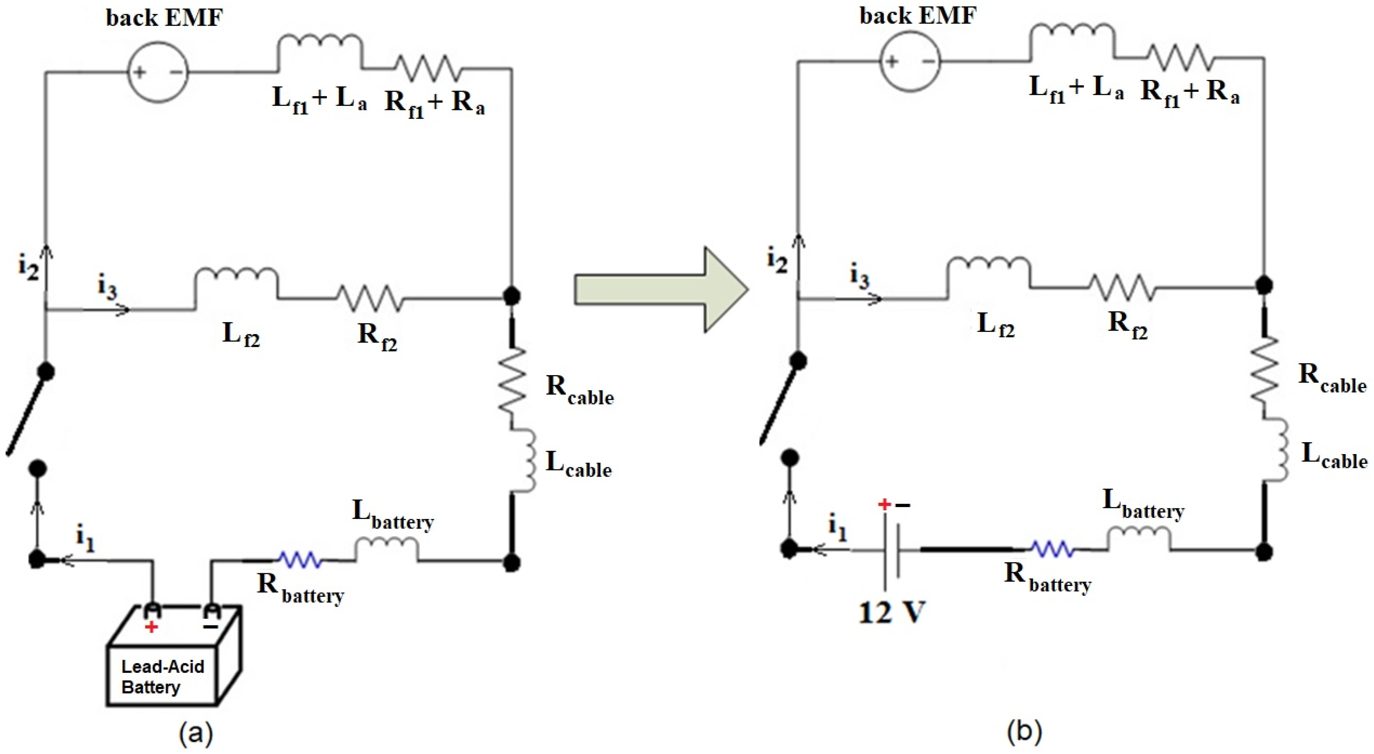
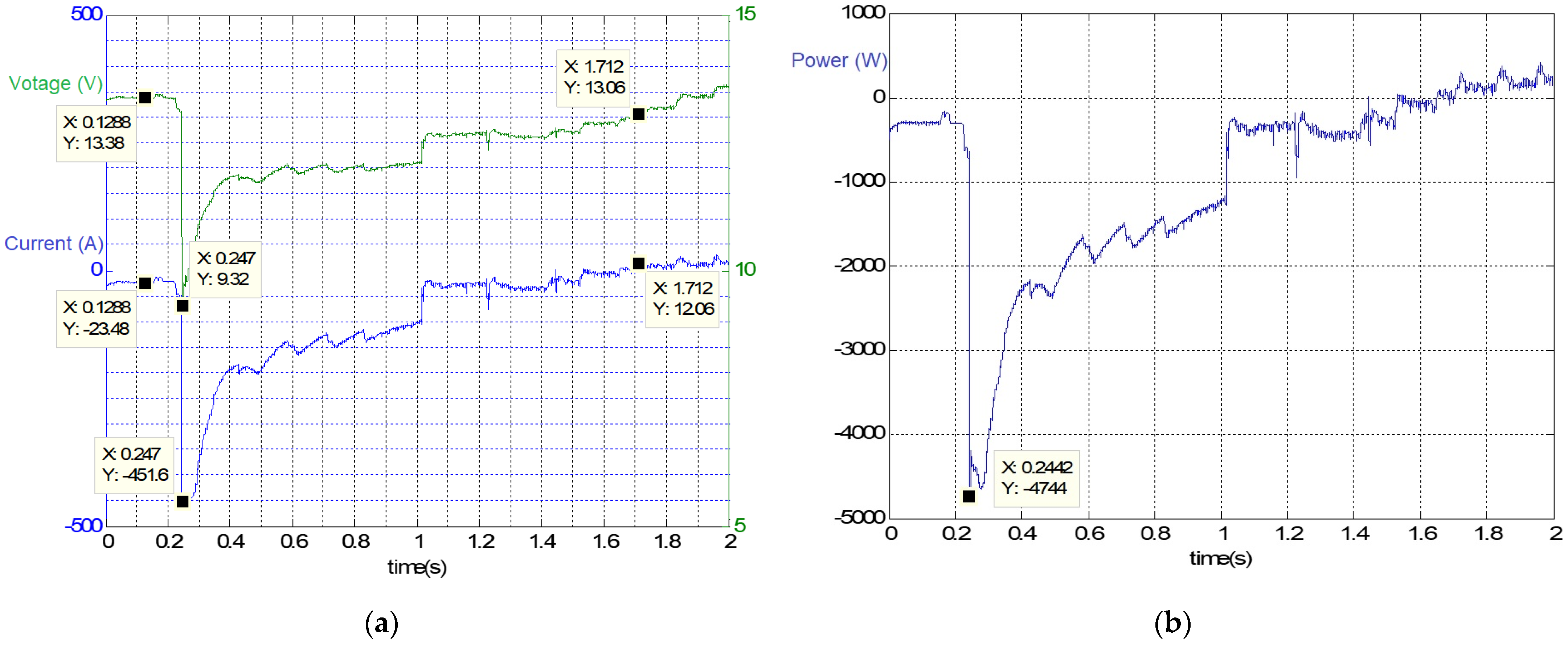
A complete generic vehicle cranking circuitry is shown in Figure 1, where the starter motor is a compound DC motor, and the battery is connected in parallel with the ultracapacitor module. The authors of [1] presented a closed-form expression for battery current in terms of the circuit parameters. A cranking test on a Ford Focus 2013 (Figure 2) was used to determine the voltage, current, power, and energy constraints and requirements imposed on this four-cylinder 2.0 L automobile.
The instantaneous power curve was obtained by taking the instantaneous product of voltage and current during the 2 s period in which the test was conducted. Running a Riemann sum on the power curve yielded the energy curve. The maximum power required during cranking was a little over 4.7 kW, and the energy required for cranking was about 1.88 kJ. Similar tests and analysis were conducted on five other car brands; the cranking results are shown in Table 1, where the voltage, current, power, and energy requirements for a number of cars from different manufacturers are recorded.
2.2. Starter Motor Modeling and Parameter Extraction
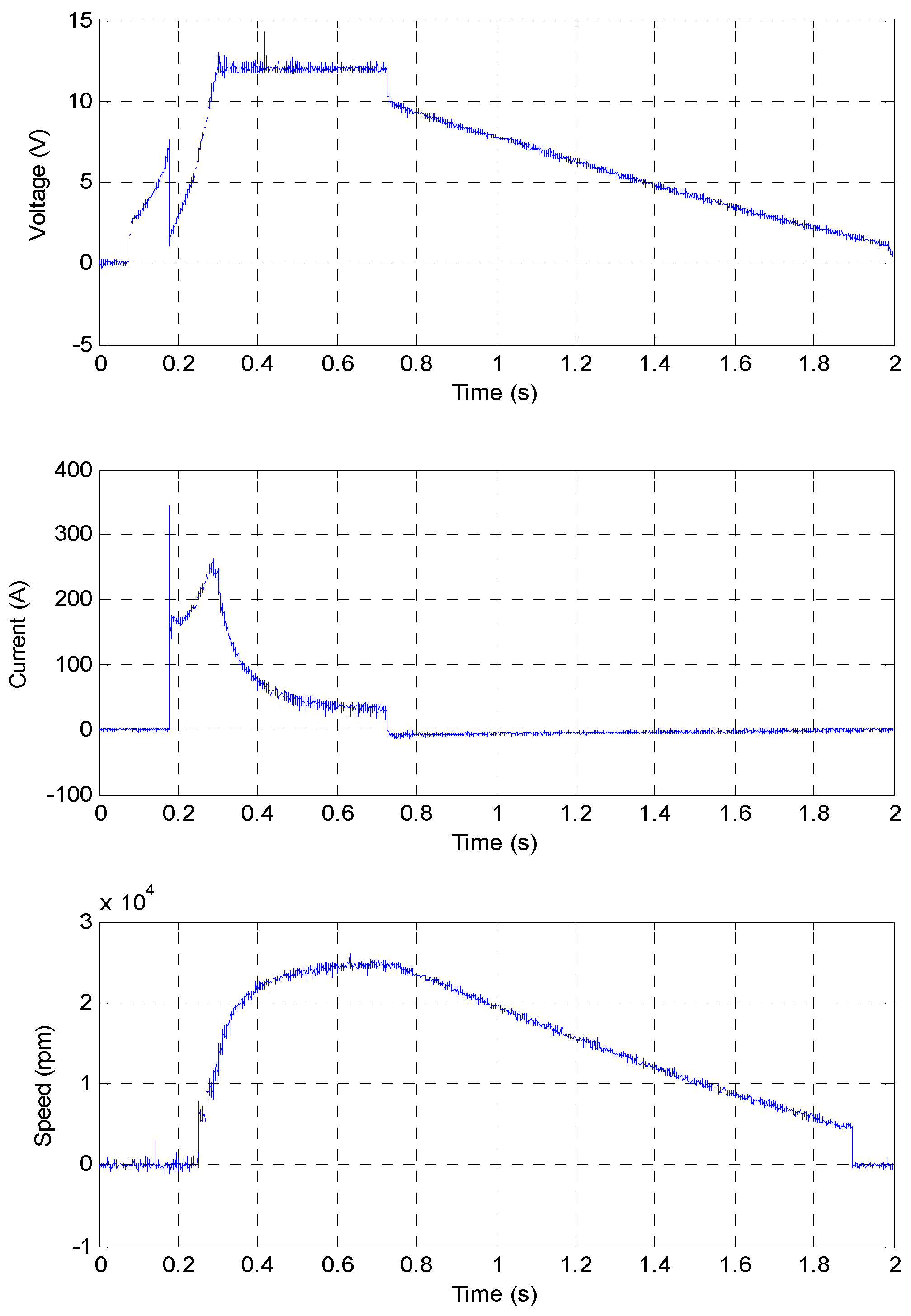
The starter motor used in this study was designed for a Saturn Vue 2004. It is a permanent magnet DC motor with its shaft gear meshed with the sun gear of a planetary gearbox. In order to mathematically model the engine cranking circuitry, simulate the circuit, and compare the results, the starter equivalent circuit parameters were extracted after applying a laboratory no-load test. A terminal voltage of 12 V was applied across the starter motor while its armature current and shaft speed were measured. The parameters extracted were the starter armature winding resistance, Rarmature, found to be equal to 22 mΩ, Larmature, found to be equal to 35.6 mH, and the winding constant, k, found to be equal to 0.00436 V∙s/rad. The starter test results are shown in Figure 3. The test involved three stages. During the first stage, the voltage applied was 12 V, but the solenoid, which was connected in series with the armature winding acting as a switch, took almost 0.1 s to close the armature circuit to the power supply. The second stage was when the voltage across the armature winding increased as the speed increased until it reached a steady state. The third stage was when the power to the starter motor was turned off, which led to a linear decrease in voltage across the armature winding as the speed decreased to zero.
3. Hybrid Energy Storage Modeling
The hybrid ESS proposed was constructed from an ultracapacitor module connected in parallel with a lead acid battery. The ultracapacitor module comprised four Li-ion ultracapacitors connected in series to meet the voltage requirement of a single automobile lead acid battery of 12 V. The use of Li-ion ultracapacitors required that they maintain a terminal voltage with a minimum of 2.2 V and a maximum of 3.8 V each. The nominal voltage for each ultracapacitor was 3 V. The voltage limits for the ultracapacitor module matched the minimum voltage requirement across the lead acid battery, its nominal voltage of 12 V, and the alternator average charging voltage of 14.4 V. This is one possibility of four for an automobile to have an energy storage system (ESS).
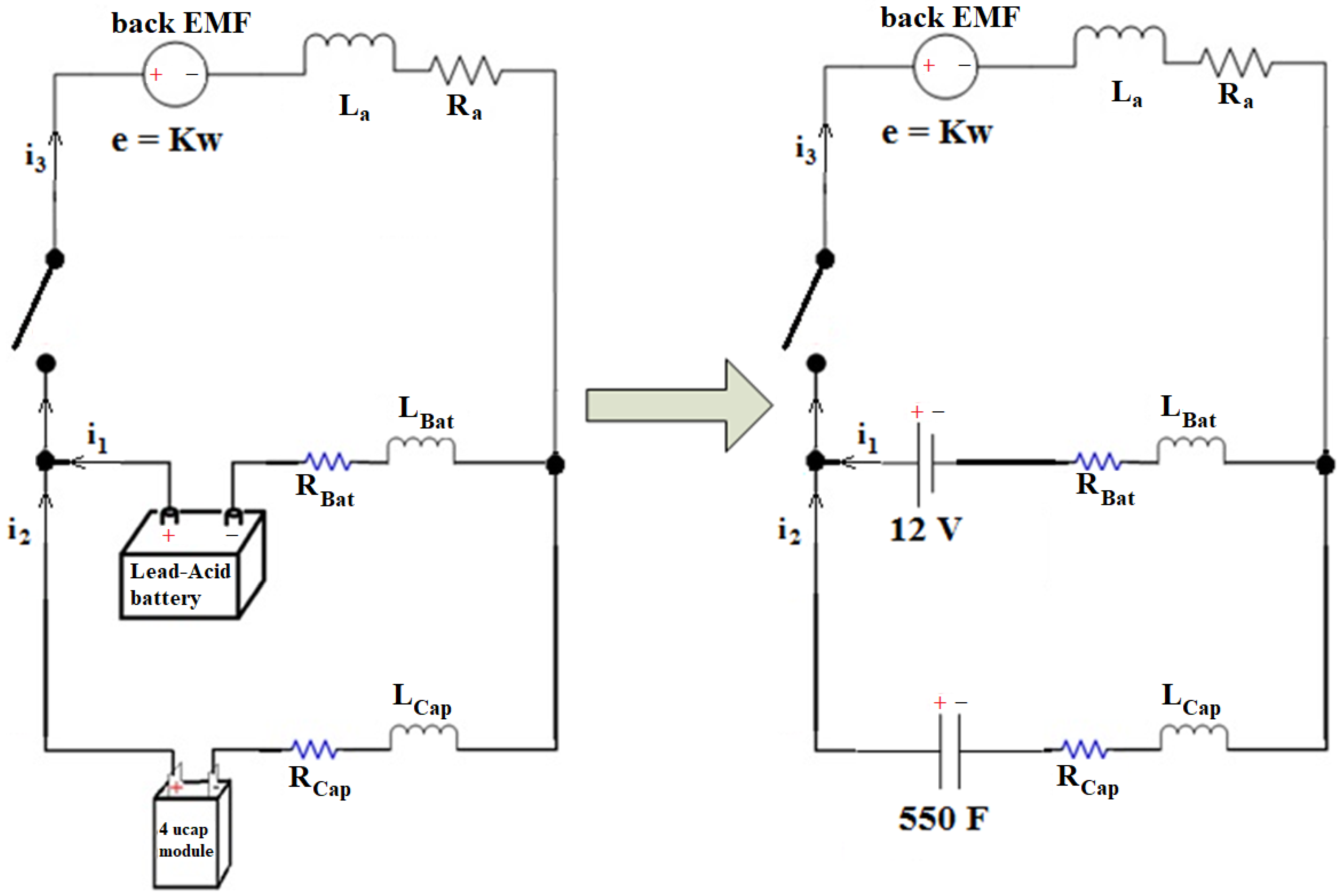
The objective of mathematical modeling was to derive an expression for the battery current as a function of the cranking circuit parameters. Using the circuit in Figure 4, which is the equivalent circuit of the starter motor for the Saturn Vue used in the experimentation, three equations were obtained after applying KVL on loops containing the ultracapacitor branch current, the battery branch current, and the armature winding current. Laplace transform was performed to put the variables in the s-domain, and then solved for the battery branch current in terms of the circuit parameters. Note that the back EMF is equal to a constant multiplied by the motor angular speed (e = Kw).
Three Kirchhoff’s voltage law (KVL) equations could be written to solve for the battery current in terms of the circuit parameters:
The equation that relates the battery current to the rest of the circuit parameters and variables in the s domain is
4. Simulation and Experimental Analysis of the Hybrid ESS
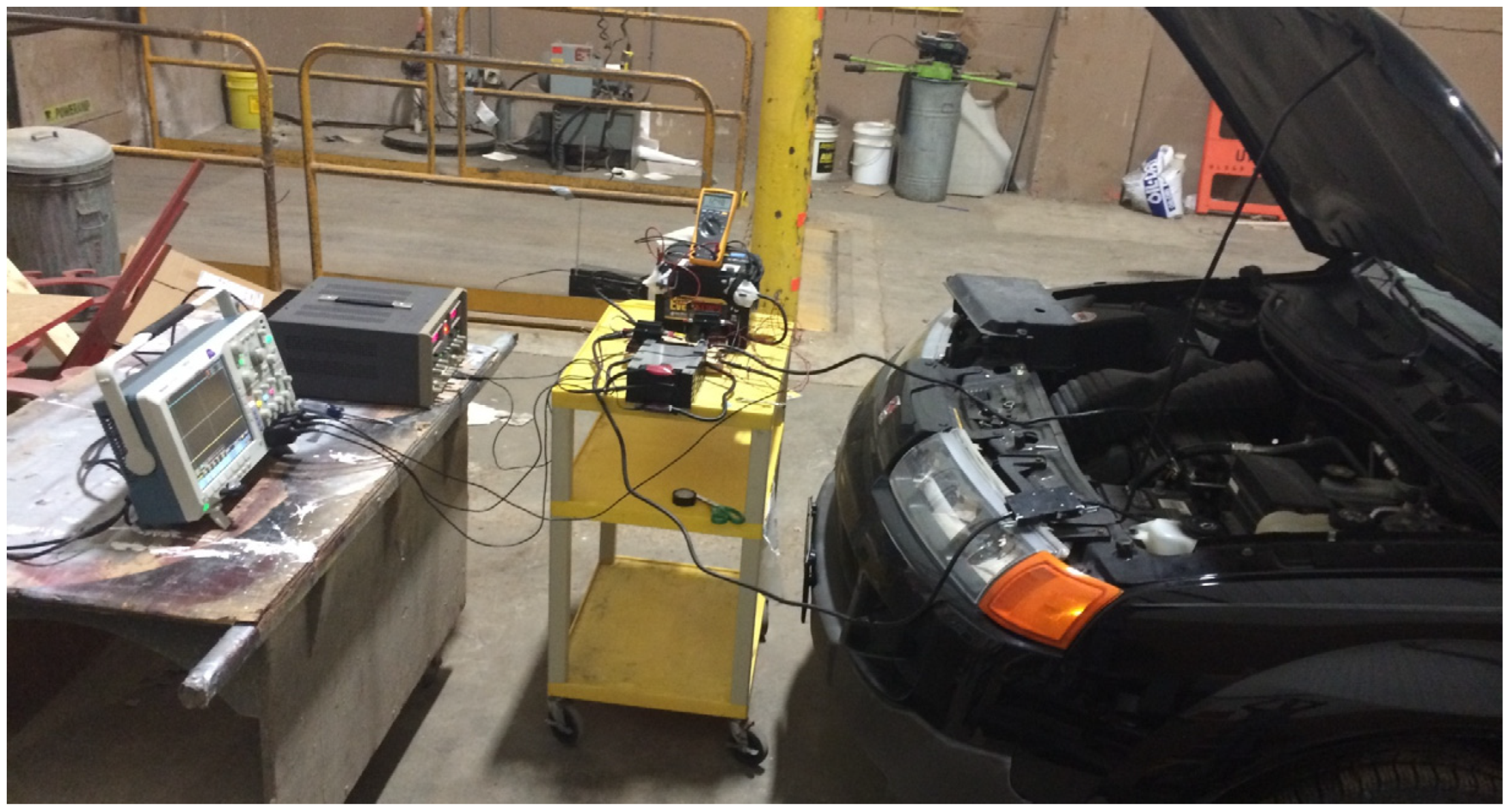
The hybrid ESS was tested on a Saturn Vue 2004 with a four-cylinder 2.24 L engine. Battery current, ultracapacitor current, hybrid ESS voltage, and engine speed were measured. Figure 5 shows the test setup. The speed was measured using a contactless laser sensor. The tests were conducted in a way that also took into consideration possibilities to shape the cranking current. Figure 6, Figure 7 and Figure 8 show the possibilities considered. All of these connections were applied and tested on the car.
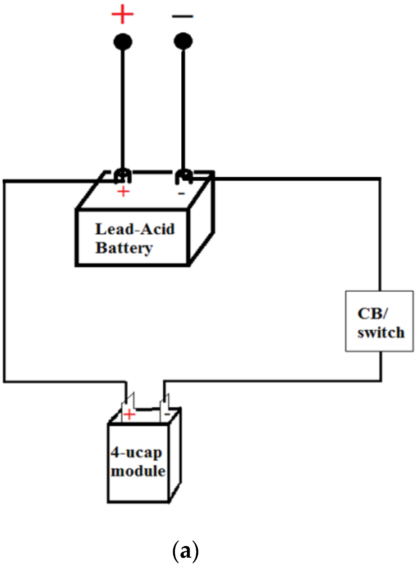
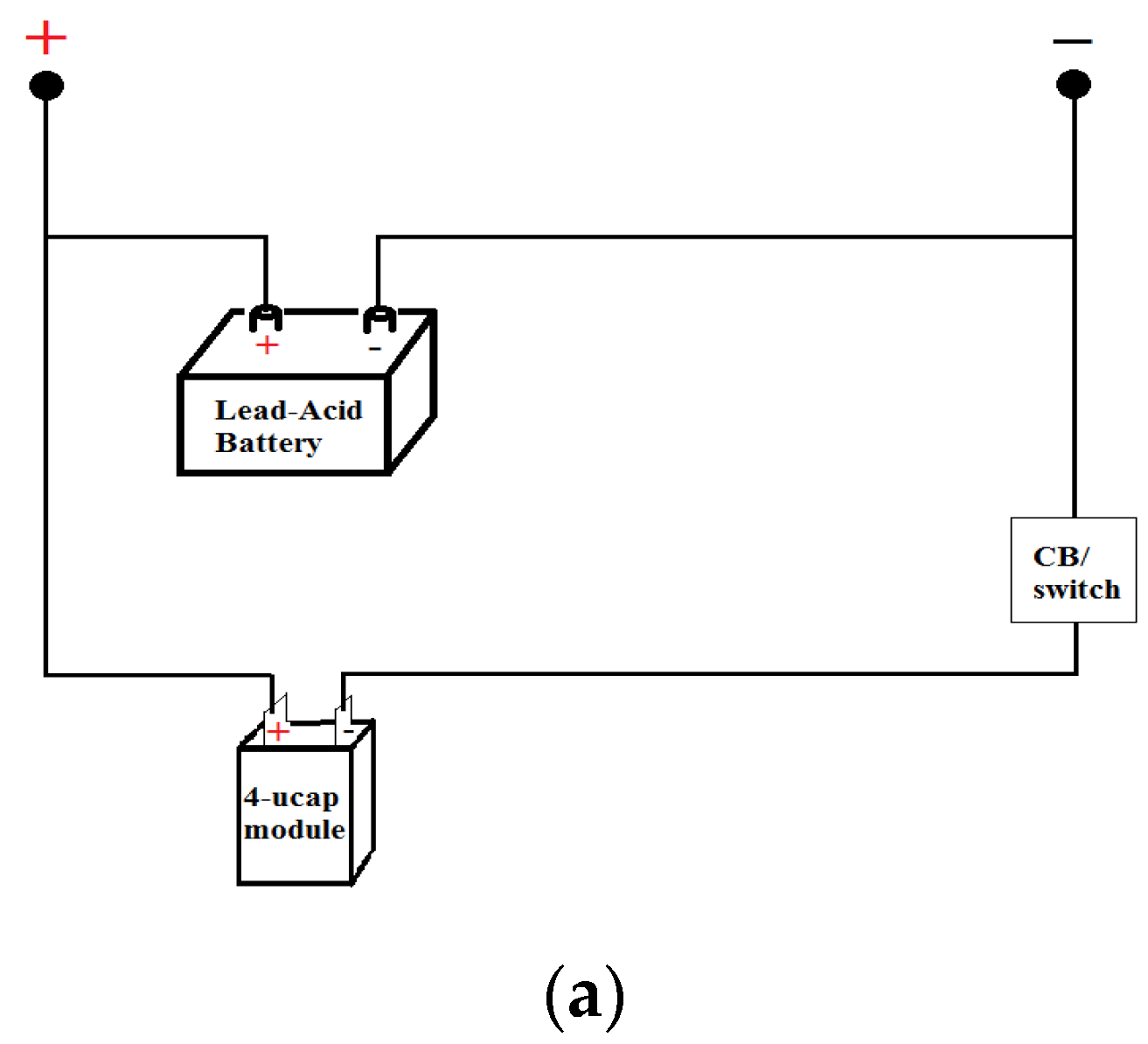
It is worth mentioning that the small resistance introduced by having an extension cable drastically changes the current response. When the direct connection is applied across the battery, the battery provides most of the cranking current. When the direct connection is applied across the ultracapacitor module, the module shows superiority during cranking. When the balanced connection is made, the ultracapacitor module still provides most of the cranking current. This gives the possibility of shaping the cranking current simply by designing a hybrid ESS with predetermined cable resistances that yield the desired cranking current sharing.
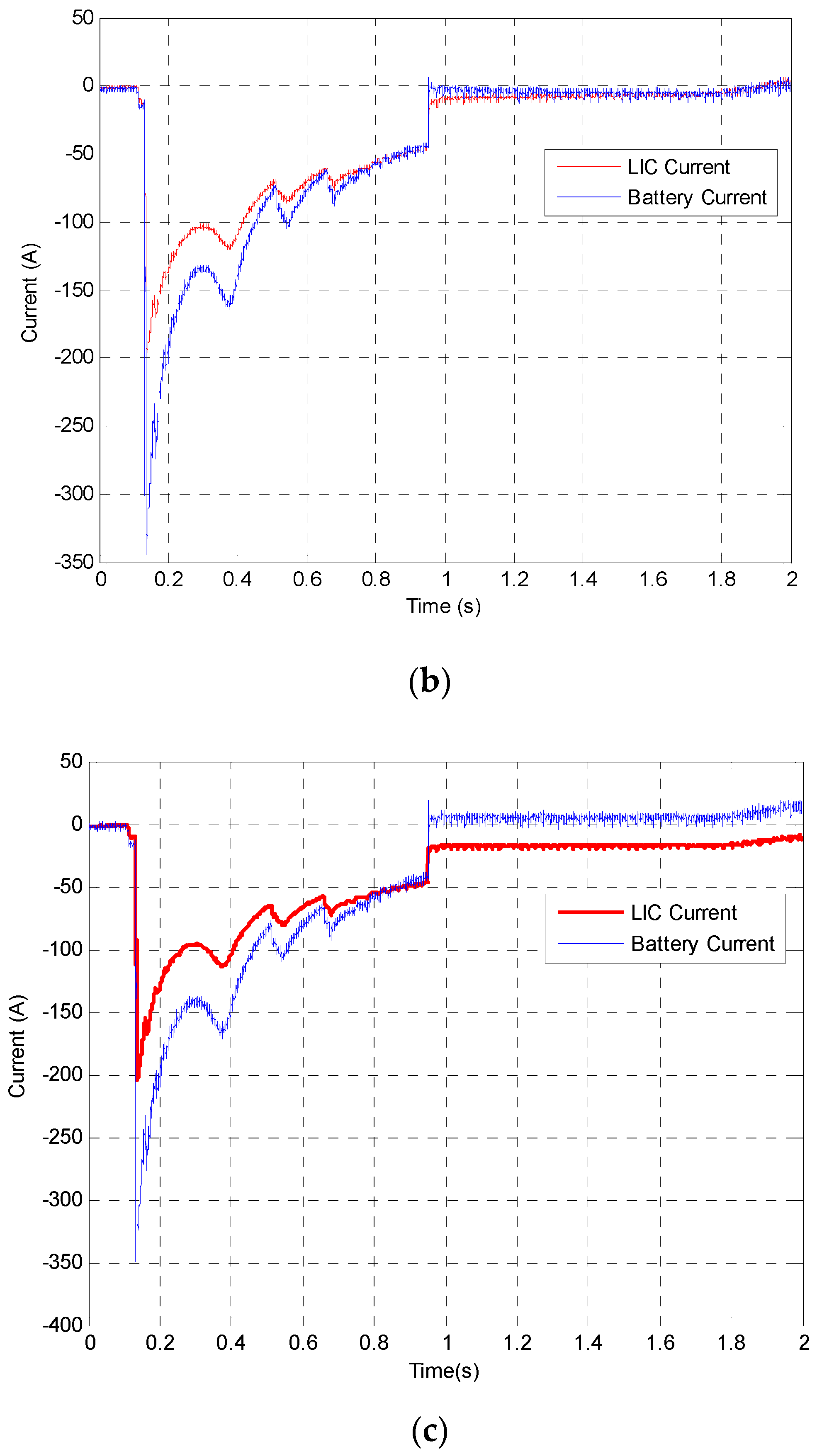
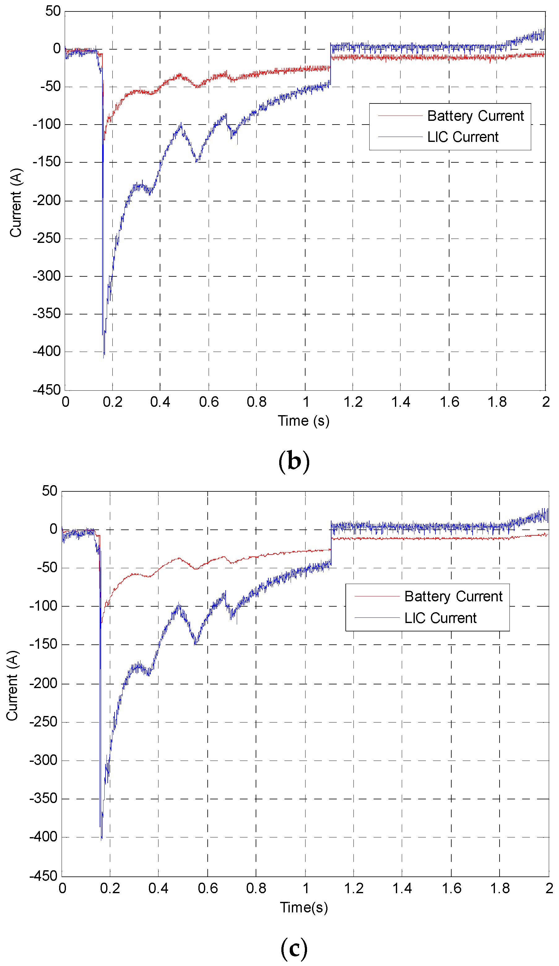
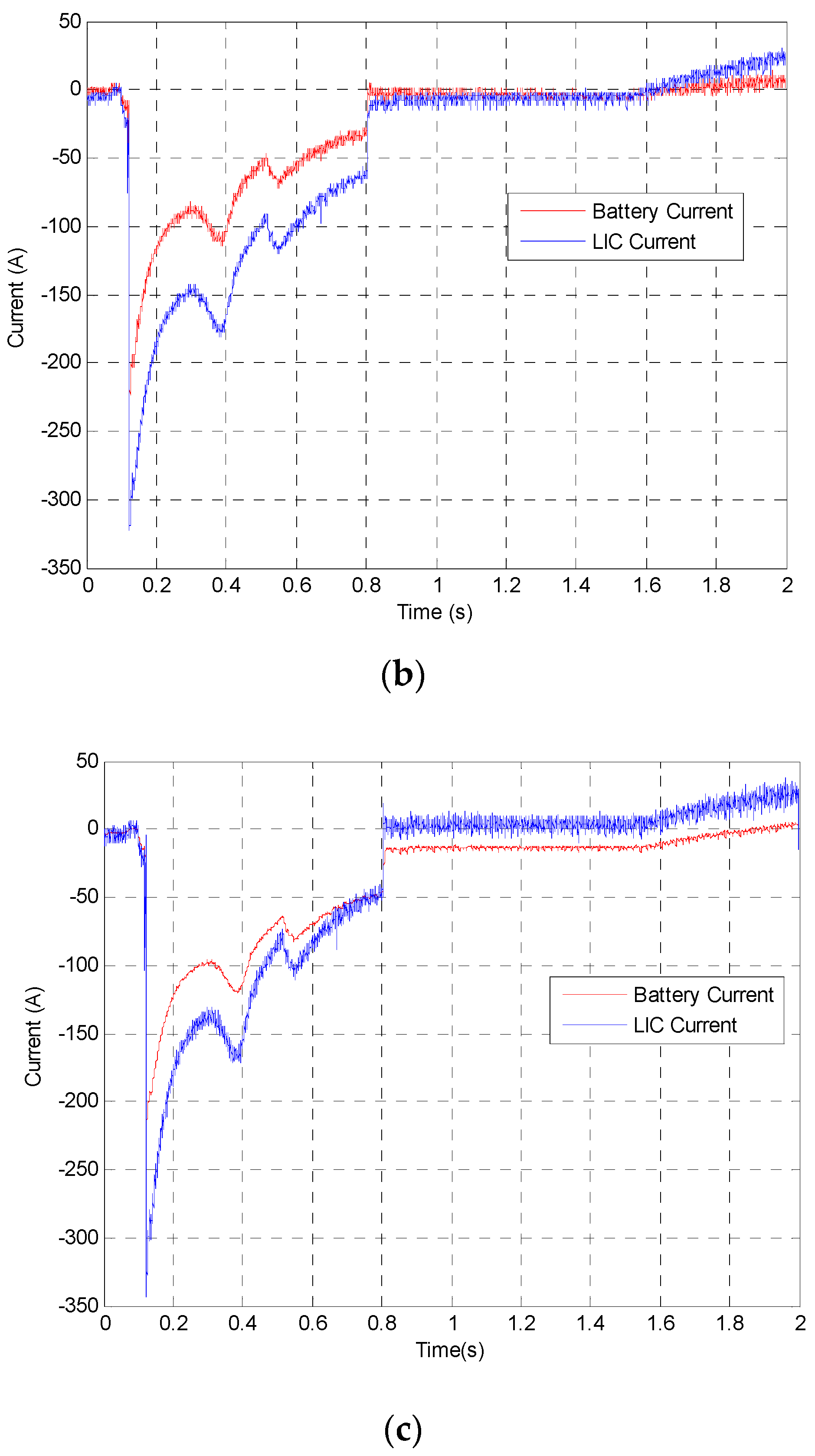
The balanced hybrid ESS connection test results on the Saturn Vue are shown in Figure 8. In the balanced connection, the ultracapacitor module provides most of the cranking current while the battery provides a smaller portion. The system voltage decreased to 11 V only compared with the low voltage of 8.3 V of the lead acid battery when used alone for engine cranking. Figure 6 shows the cranking currents of the hybrid ESS for the battery biased connection, Figure 7 shows the cranking currents for the ultracapacitor biased connection, and Figure 8 shows the cranking currents for the balanced connection.
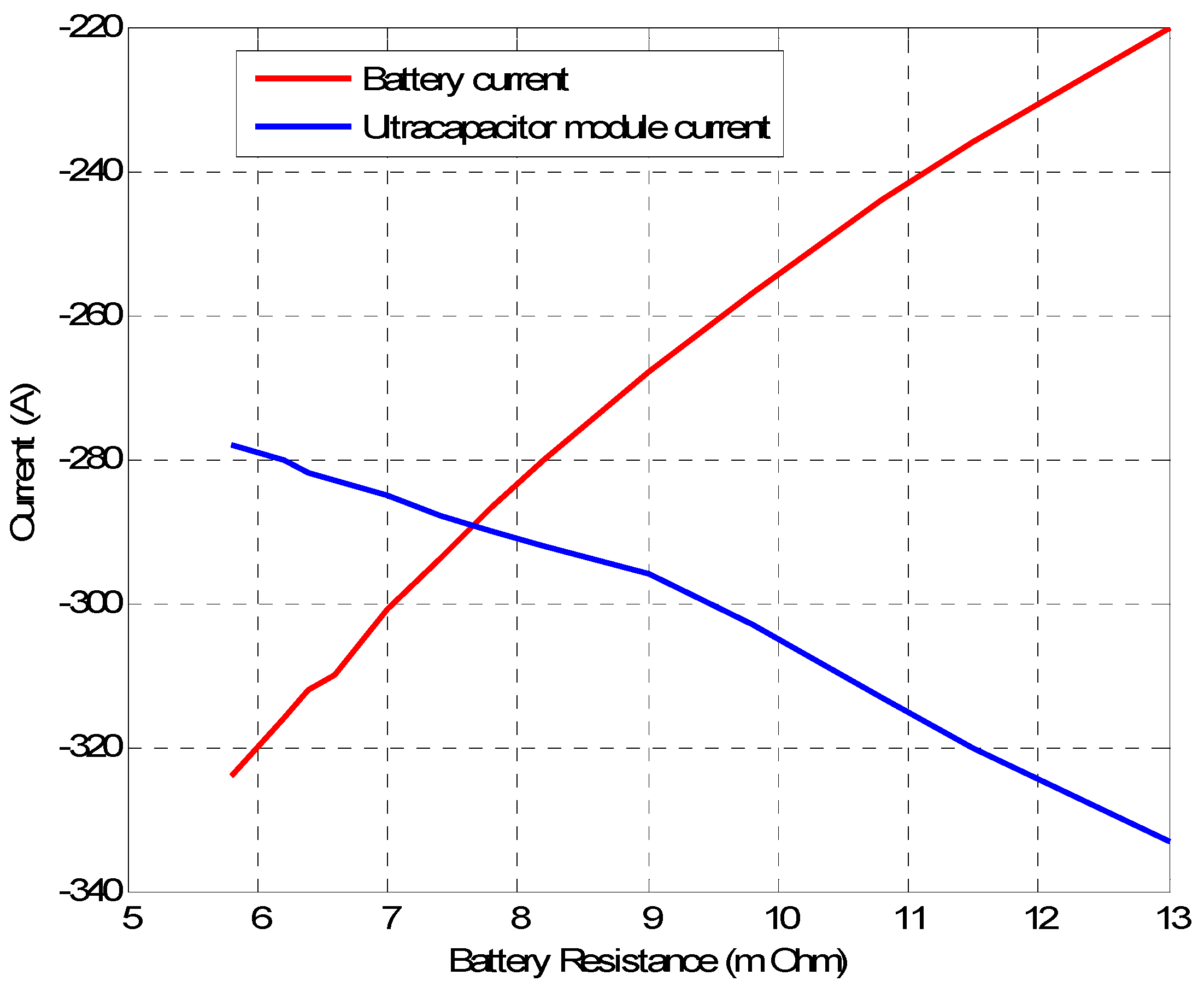
One effective technique to control the cranking current shared by the Li-ion ultracapacitor module and the lead acid battery is to control the branch resistances. Varying the cable length for the battery or ultracapacitor module changes the current sharing drastically. This was tested experimentally and simulated to see the effect of branch resistance. In Figure 9, the maximum cranking current was simulated for a battery branch resistance of 7 mΩ while the ultracapacitor branch resistance was allowed to vary. The two current waveforms should be added together to get the total cranking current waveform.
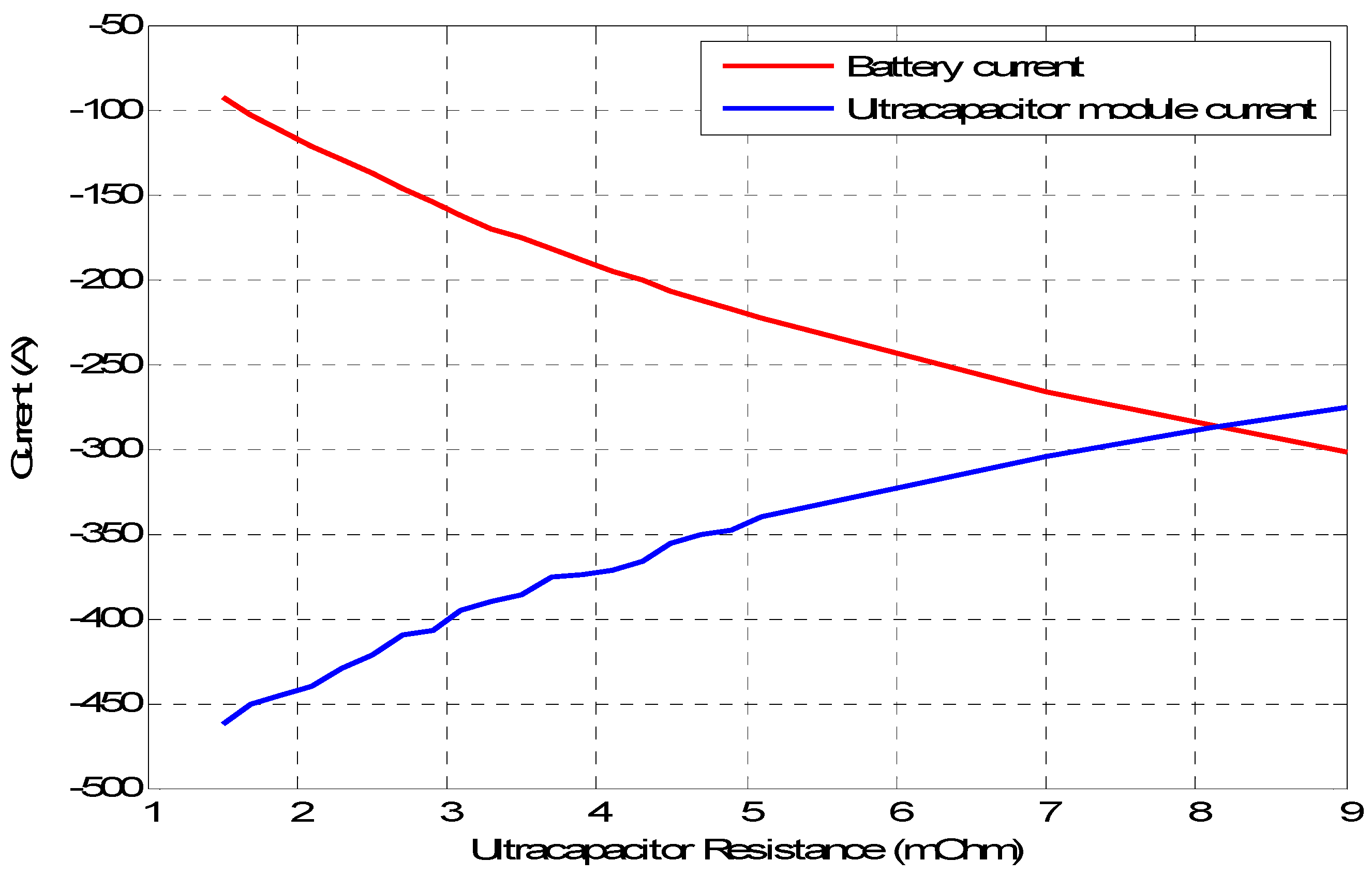
It can be noticed that an increase of a few mΩs of ultracapacitor branch resistance could result in a massive increase in battery branch cranking current contribution and a massive decrease in the battery branch contribution. Figure 10 shows the opposite case where the ultracapacitor branch resistance was kept constant at 9 mΩ while the battery branch resistance was allowed to vary. Similar observations can be made especially the sensitivity of maximum cranking current to the branch resistance value.
5. Age Estimation of the Hybrid ESS
5.1. Aging Parameters
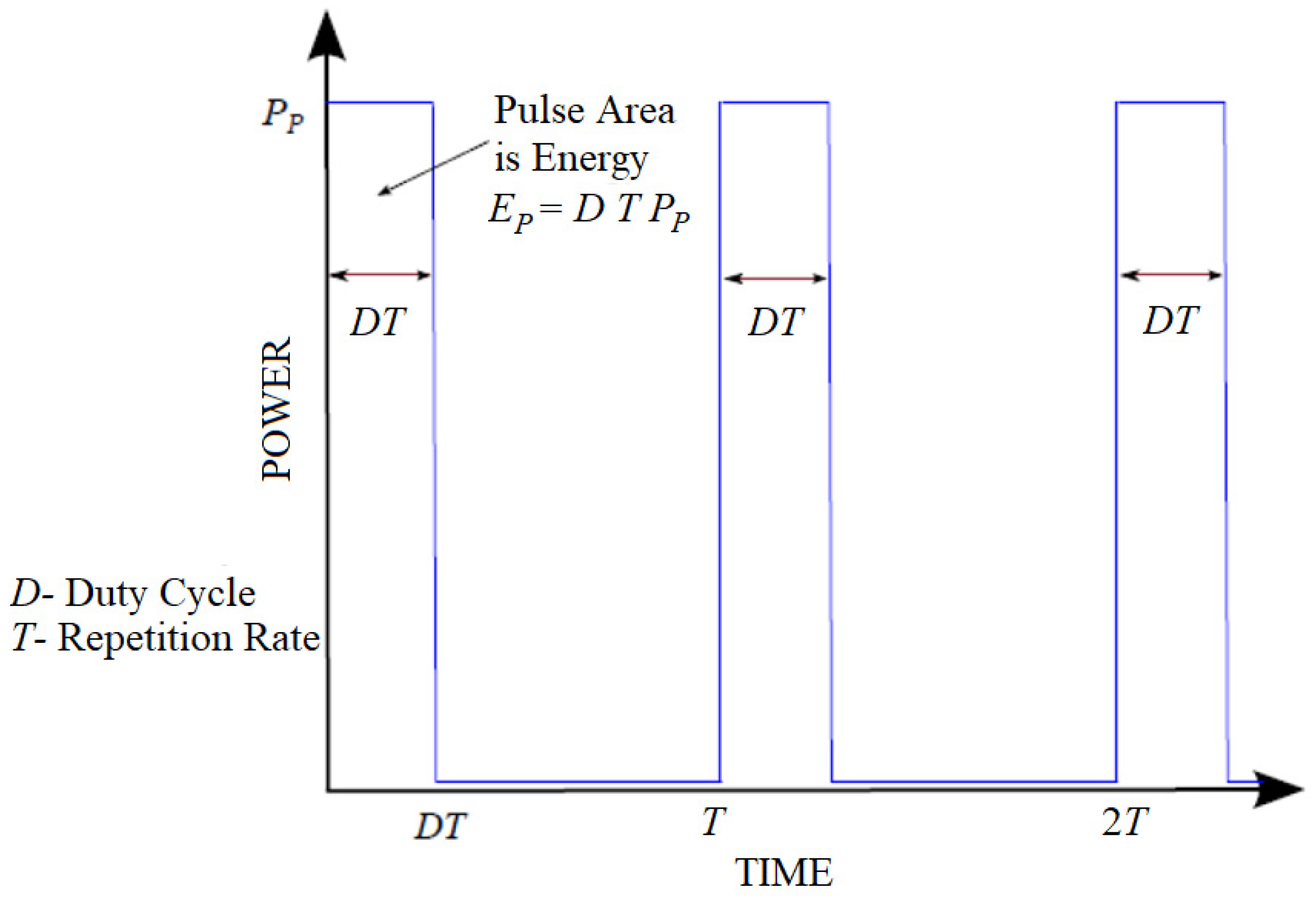
The cranking profile presented so far in this paper is a perfect example of a pulsed power profile. Any energy storage system having to provide such power even for a short period of time experiences stress, leading to its gradual aging. In this section, a number of parameters designed to quantify the stress a battery goes through during engine cranking, as well as quantify the benefits gained from combining a battery with an ultracapacitor module in a hybrid ESS, are presented. In a study by JSR Micro, five parameters were introduced to assess the overall performance of such a hybrid ESS considering system cost and performance based on the power profile shown in Figure 11 [27]. In Figure 11, the duty ratio is D, the period is T, and the product DT is the period during which the pulsed power is required from the ESS.
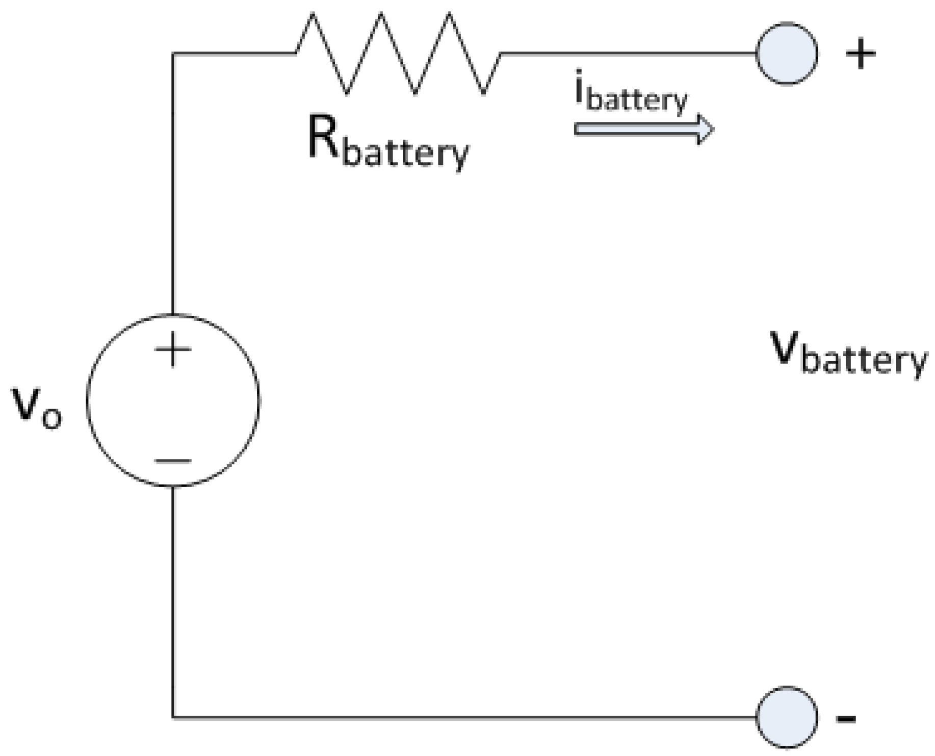
In this study, a basic energy storage system model was used. In particular, a lead acid battery equivalent circuit model was used to derive the equations that define the energy, capacity, and power required during the pulse period. Furthermore, all aging parameters were also defined on the basis of this equivalent circuit model and the simplified pulsed power profile mentioned earlier. The lead acid equivalent circuit used in this study is provided in Figure 12.
The amount of charge provided by the battery during a single pulsed power interval is given by Equation (5).
The five parameters proposed by JSR Micro are presented next. These parameters characterize the battery on different levels; they are generalized for pulsed power profiles such that they apply to a wide range of pulsed power applications not exclusive to the profile on which the aging study is based, and they are normalized with a value that ranges between zero and one. A sixth parameter relevant to the proposed hybrid ESS is also presented.
5.1.1. Battery Loading Factor (BLF)
This parameter provides a measure of the battery loading. Since loading is directly affected by the amount of current going through the battery, especially during discharging, one possible equation that can be used to construct this parameter is given below.
where x(t) shows direct proportionality with the battery current; however, it does not show the peak power of the pulsed power profile. This equation can be used toward defining the BLF by defining the parameter expressed in Equation (7).
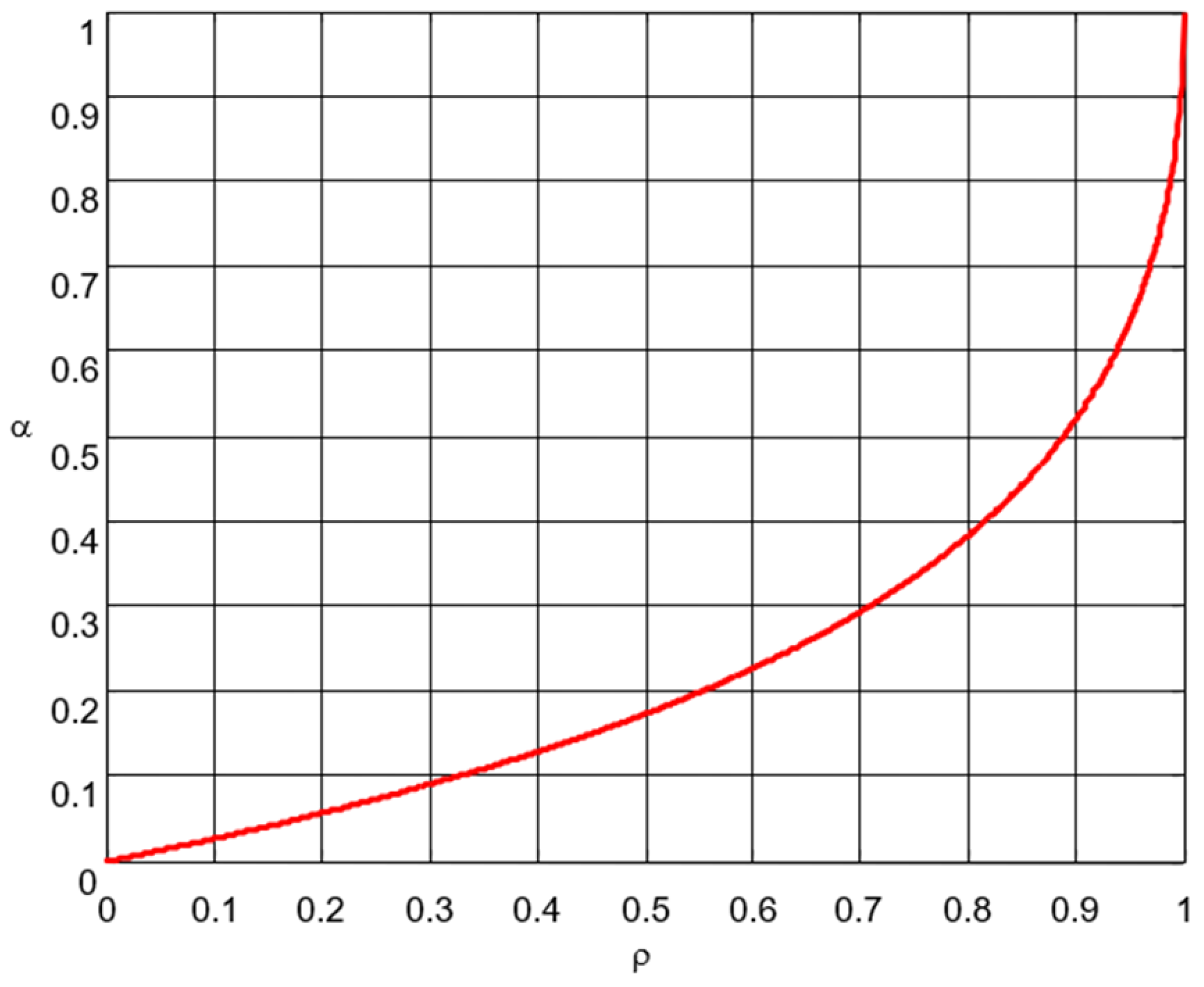
where ρ satisfies all the properties that the aging parameters are to have; it is a unitless, normalized, monotonically increasing function of the peak power demand. ρ was, therefore, elected to be the BLF.
5.1.2. Battery Stress Factor (BSF)
Batteries experience stress when being charged or discharged at a much higher current than the rated current. The current passing through the battery causes thermal stress. A parameter showing the stress undergone by the battery is defined as the ratio of energy loss as heat versus energy deliverable to the load; this parameter is given in Equation (9).
5.1.3. Hybrid Improvement Factor (HIF)
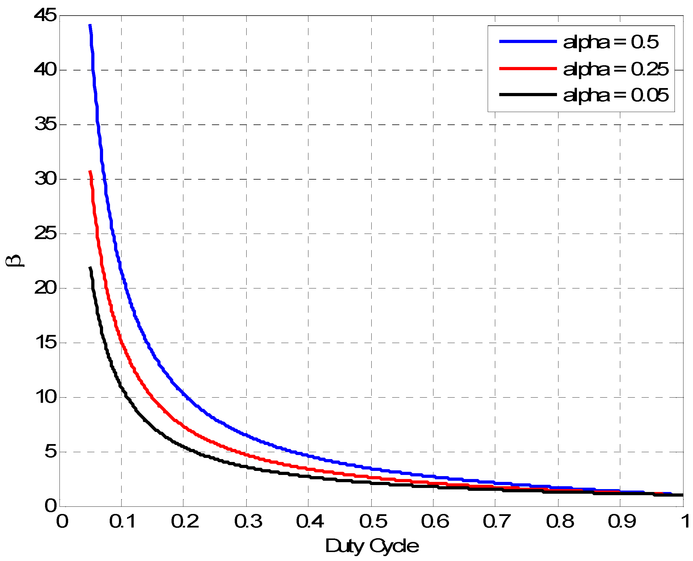
This parameter provides a unitless measure of improvement introduced by the hybrid ESS versus battery alone, defined in Equation (10).
where HIF is a parameter that is highly sensitive to the duty cycle, and µ is a scale factor used to compensate for the efficiency of any DC–DC converter used in the battery/ultracapacitor hybrid energy storage system. If the efficiency of the converter is larger than 90%, µ can be approximated to unity. The hybrid ESS proposed in this paper has no converter in its design, in which case µ is equal to 1. Figure 14 shows HIF curves for different cases of BSF plotted versus duty cycle. HIF is higher for smaller duty cycle values. During cranking, the duty cycle is extremely small, which renders the hybrid design very useful from an HIF perspective.
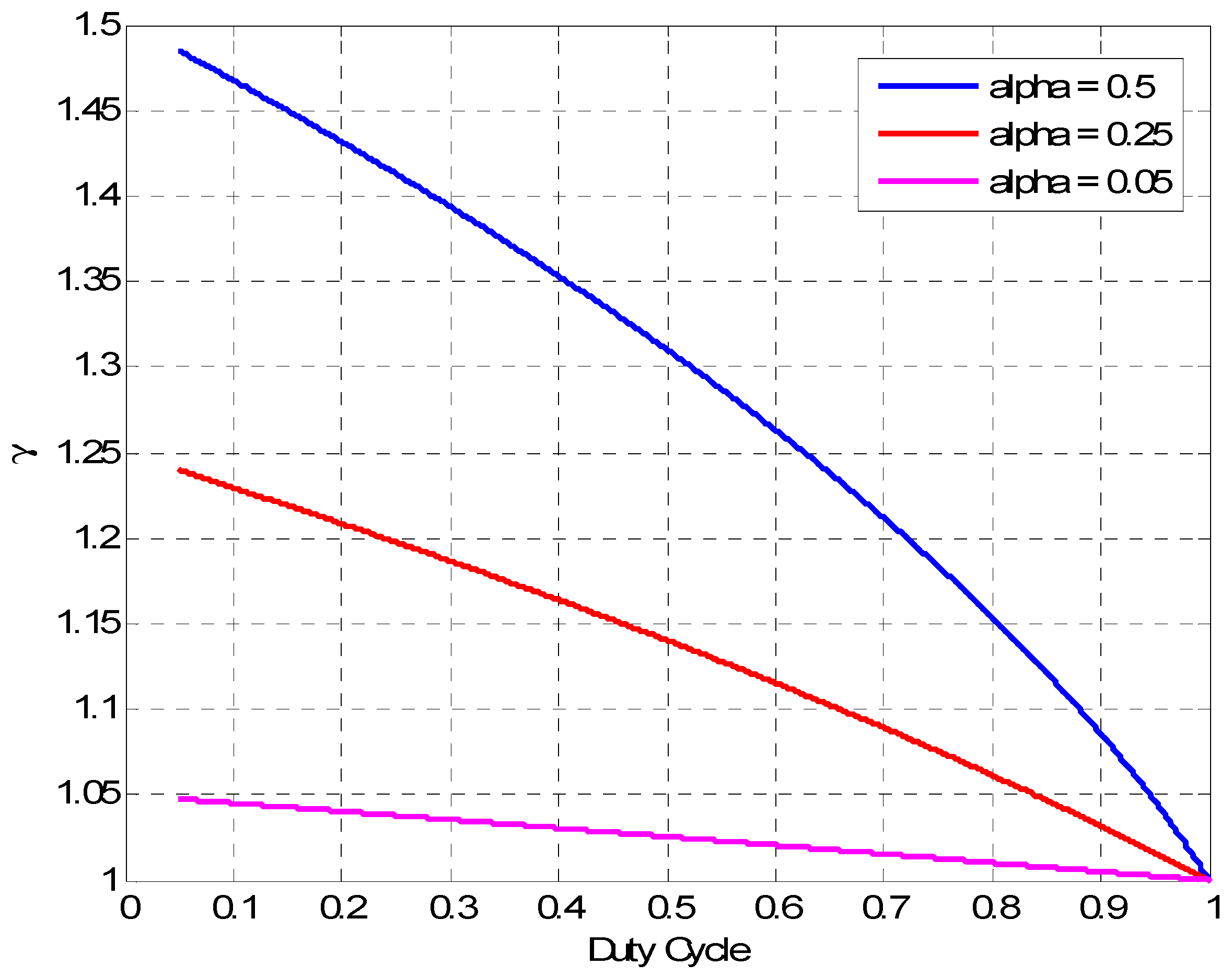
5.1.4. Charge Capacity Factor (CCF)
This parameter is an instantaneous unitless measure of charge capacity used from battery versus charge capacity used from the hybrid ESS, as shown in Equation (11).
CCF can be plotted versus duty cycle as shown in Figure 15. It is obvious that the value of CCF hovers around unity. This is due to the fact that the addition of an ultracapacitor module to the lead acid battery does not add much capacity to energy storage. The capacity in an ultracapacitor is only a small fraction of that of a battery.
5.1.5. Energy Capacity Factor (ECF)
This parameter provides an instantaneous unitless measure of the energy capacity used from battery in a hybrid system versus energy capacity used from battery alone. Equation (12) shows the definition of ECF.
A smaller ECF denotes more effective hybridization. The ideal case would be when BLF is equal to zero, meaning that the contribution of the battery in the hybrid setting is equal to zero during cranking. ECF is an important factor to consider for batteries that are smaller in size or not capable of storing a relatively large amount of energy, which is not the case for automobile batteries. However, energy consideration is always essential in any energy storage hybridization study. The next parameter has more importance than ECF in our specific case.
5.1.6. Peak Power Factor (PPF)
This parameter is defined as the ratio of the peak power the battery provides in a hybrid system versus the peak power provided by a battery alone during a pulse power period as shown in Equation (13).
This parameter has much more importance than the ECF in the proposed system since instantaneous power during cranking is a major concern rather than cranking energy, which is miniscule compared with the overall capacity of automobile batteries.
5.2. Aging Parameter Results
The values of the aging parameters in cranking tests were calculated for the battery in the hybrid ESS, as well as when used alone to crank the engine for both cold and warm cranking events. The battery loading factor, battery stress factor, peak power factor, and hybrid improvement factor were calculated as a function of the maximum cranking current. The charge capacity factor and energy capacity factors were calculated over the entire period of time during which cranking took place. Under cold cranking, the battery loading factor decreased from 0.995 to 0.55, and the stress factor decreased from 0.866 to 0.197 as a result of integrating the battery with the ultracapacitor module in the hybrid ESS. As for warm cranking, the battery loading factor decreased from 0.743 to 0.443, and the stress factor decreased from 0.743 to 0.145 as a result of hybridization. The improvement factor for cold cranking was 4.4 meaning that the battery inside the hybrid ESS was 4.4 times less stressed than the battery alone. As for warm cranking, HIF was 5.5. The charge capacity factor was 14.99 and 8.23 for cold cranking and warm cranking, respectively. That means that the battery alone provided 14.99 times the capacity of the same battery in the hybrid ESS. The energy capacity factor was 13.92 and 7.5 for cold cranking and warm cranking, respectively. That means that the battery alone provided 13.92 times the energy of the same battery in the hybrid ESS. These results show a significant improvement of the loading conditions for the battery in the proposed hybrid ESS versus the battery alone. In summary, loading and stress were reduced, while HIF, CCF, and ECF were increased. Table 2 shows the aging parameter values calculated for each cranking case.
5.3. Experimental Capacity Study
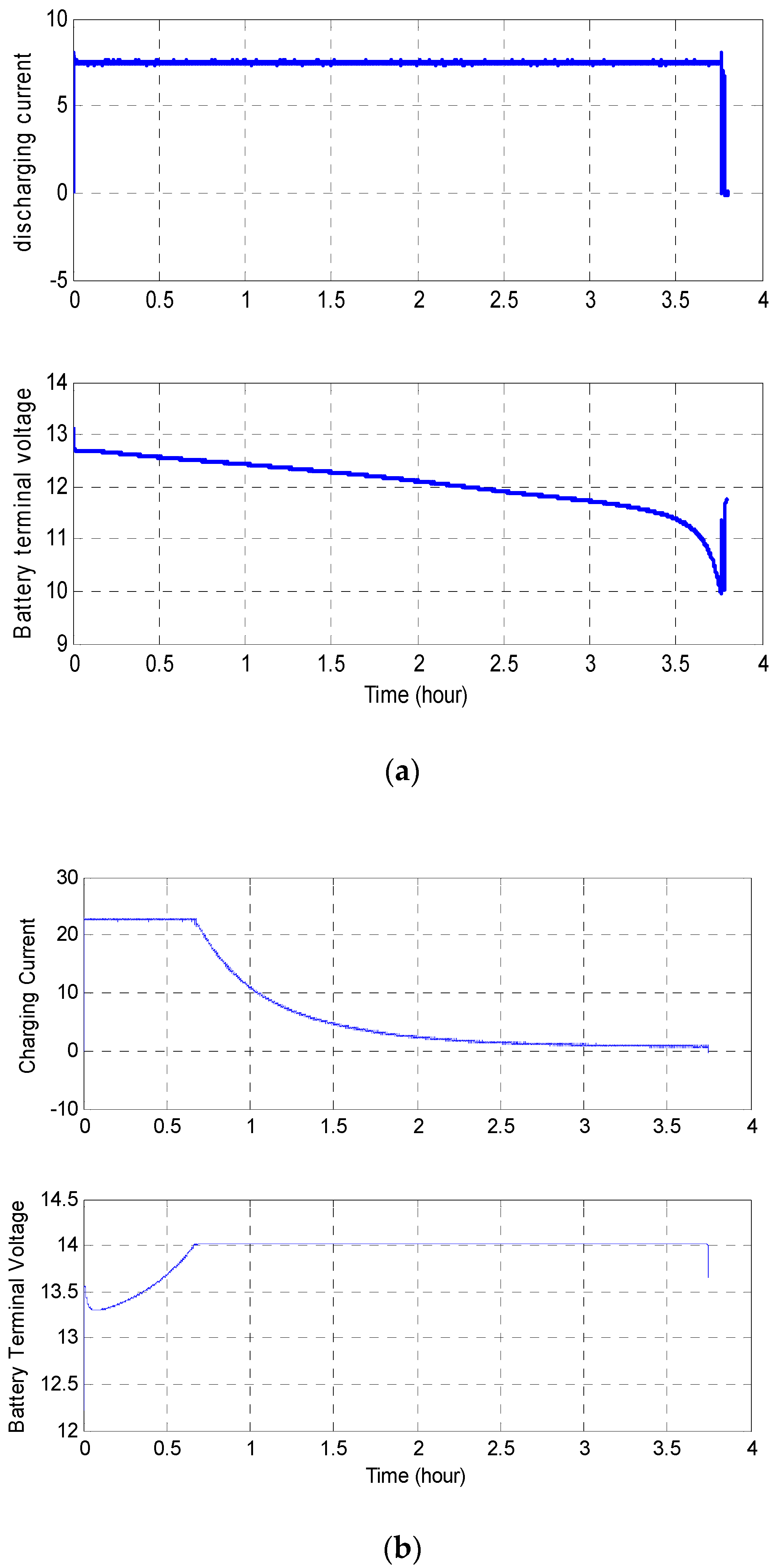
The capacity of the batteries used in the two ESS systems, a battery alone and the battery integrated into the proposed hybrid ESS, was measured after steps of 200 cranking events. Ten steps for each ESS were performed, totaling 2000 cranking test per ESS. The battery capacity test involved discharging the ESS at 7.5 A until the ESS terminal voltage reached 10 V, from which the capacity in Ah was calculated. The battery was then recharged in constant voltage mode until the charging current reached a value less than 1A. Figure 16a shows the current and voltage waveforms obtained for one capacity measurement, while Figure 16b shows the charging event current and voltage waveforms.
Table 3 shows the capacity measurement values after each of 10 cranking steps applied to the battery alone and the hybrid ESS. It is worth noting that the battery inside the hybrid ESS sustained obviously larger capacity after the fifth step. Each step denotes 200 cranking events performed. Both batteries were given a break of 3 weeks between the fifth and sixth steps. They showed a sign of false recovery at the sixth step and continued to lose capacity as cranking steps were applied to them afterward.
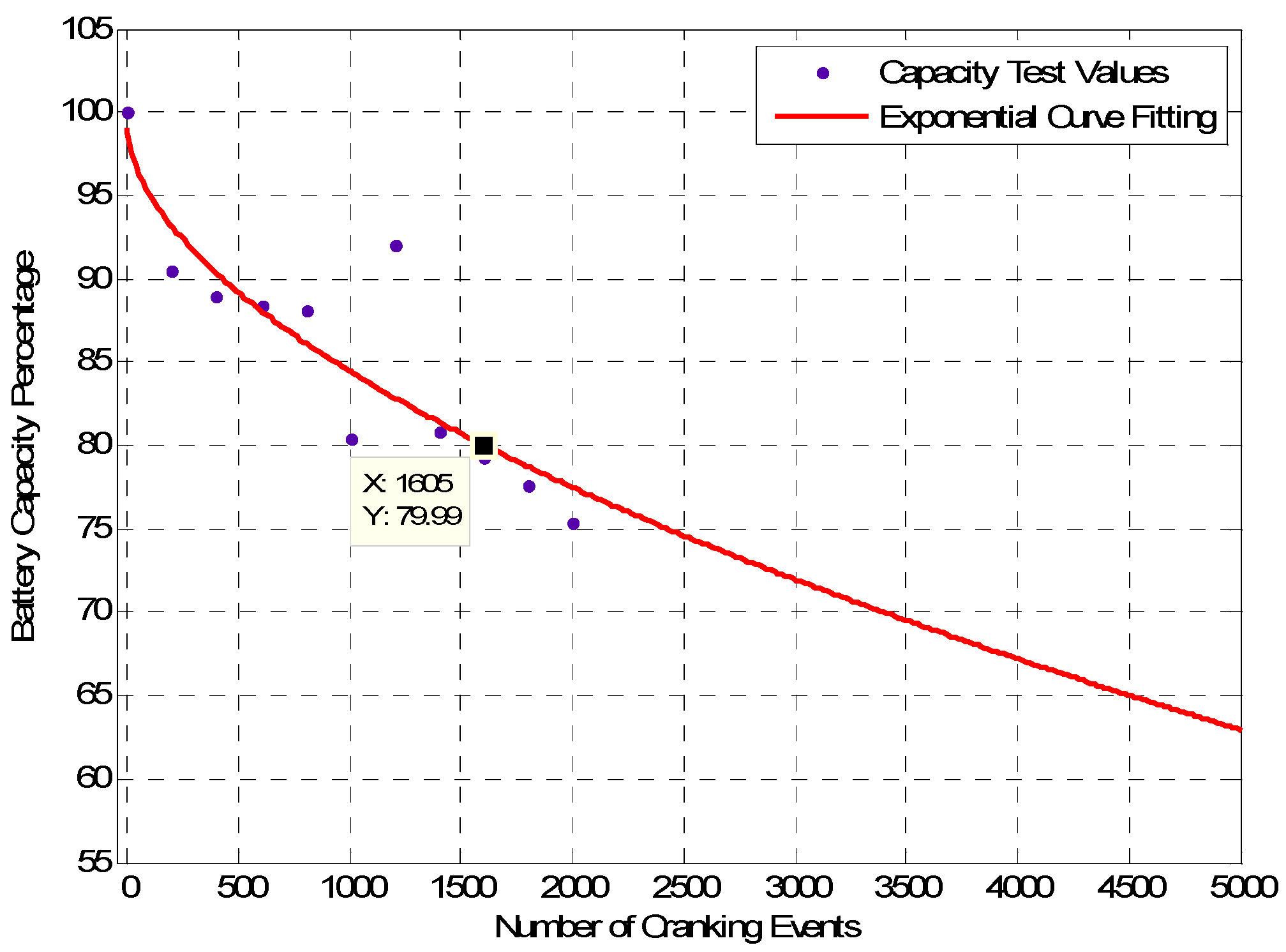
Judging from Table 2, as well as the values calculated for aging parameters, there was empirically verified correlation between hybridization and the capacity sustained in the battery inside the hybrid ESS versus the battery alone that experienced a significant drop in capacity after 1000 cranking tests. While there are no clear models that predict aging of lead acid batteries, given the diagnostic nature of the aging parameters, it can be deduced that the aging parameters can be used to predict battery age. Nevertheless, more data points are needed to know when the battery reaches a low capacity, making it unfit for automotive applications. The limit set by IEEE standards is 80% of the nominal battery capacity. After this limit, the battery is considered a second-life battery. This can be investigated experimentally on a brand new battery until it reaches a value of capacity at which the battery cannot provide enough power to crank the engine. While conducting these tests over presumably several thousands of cycles, voltage and current can be recorded and the aging parameters can be calculated. This enables the possibility of monitoring the progress of aging parameters as the battery is aging, i.e., while its capacity is periodically measured, until it reaches its end of life. The same tests can be performed on a sample of lead acid batteries large enough to be used to establish a lookup table for lead acid battery age estimation. All of the aging parameters defined in this paper could be used together to estimate the battery age after creating the six-dimensional lookup table corresponding to the six parameter values obtained from the tests. An X-labeled battery with unknown history can, thus, be tested once, and then the lookup table can be used to estimate its age after fitting its aging values. Extrapolation can be used to estimate the number of cranking events it takes to render the battery as a second-life battery. Figure 17 shows the capacity of the battery alone versus the number of cranking events. According to the exponential fit provided, the battery reached 80% of its nominal capacity after 1600 cranking events. This is the point at which the battery would be considered second-life.
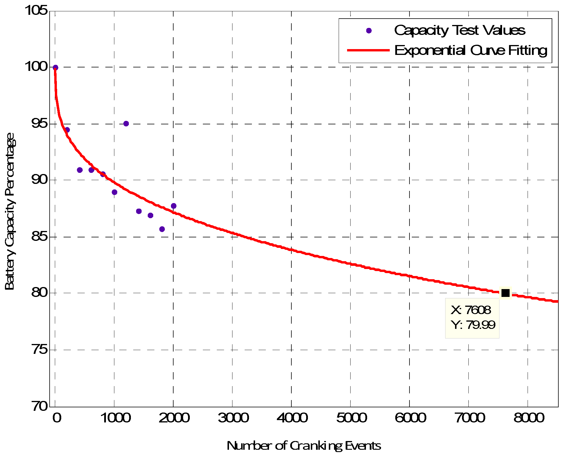
Figure 18 shows the capacity of the hybrid battery versus the number of cranking events. According to the exponential fit provided, the battery reached 80% of its nominal capacity after 7600 cranking events. This is the same point at which the battery would be considered second-life. This is 4.7 times the number of cranking events that rendered a battery alone unfit for first-life cranking.
6. Conclusions
This paper presented the age estimation of a hybrid ESS made from a lead acid battery and an ultracapacitor module. First, the hybrid ESS was modeled, simulated, and then tested to verify its ability to serve during the cranking of an automobile internal combustion engine. This was the first milestone of the project. The test and simulation results verified that the cranking current stressed the battery, causing a shortened battery life span. The major benefit of the ESS is that the ultracapacitor module can handle the majority of the current during cranking events, which reduces the stress on the battery, leading to an extension of its life. A study was then presented to quantify a number of parameters that can be used to measure an ESS loading, stress, improvement from a hybrid setup, capacity improvement, energy improvement, and peak power improvement. Experiments were conducted to prove the validity of the proposed hybrid ESS. Furthermore, a method was proposed to use the aging parameters in order to predict the life span of lead acid batteries based on experimentation. Extrapolation of the battery capacity versus cranking events curves shows that a battery in a hybrid system could live almost five times longer than a lead acid battery alone in a start–stop automobile. The battery age analysis and estimation in this paper followed traditional cyclical engine cranking. There are other methods to study and estimate the age of batteries, including dynamic battery cycling, which has been shown to outperform traditional methods in terms of accuracy of estimation [28]. It is clear from the results of this paper that integrating Li-ion ultracapacitors with lead acid batteries for the start–stop application can achieve the objective of saving gas and reducing greenhouse emissions while preserving the life span of batteries. It is recommended that car manufacturers that utilize lead acid batteries incorporate this solution in their battery design.
Author Contributions
Conceptualization, E.M. and A.N.; methodology, E.M.; software, A.N.; validation, E.M. and A.N.; formal analysis, E.M. and A.N.; investigation, E.M. and A.N.; resources, A.N.; data curation, E.M.; writing—original draft preparation, E.M.; writing—review and editing, E.M. and A.N.; visualization, E.M. and A.N.; supervision, A.N.; project administration, A.N.; funding acquisition, A.N. All authors have read and agreed to the published version of the manuscript.
Funding
This research was funded by JCI.
Data Availability Statement
Data is unavailable due to privacy restrictions.
Conflicts of Interest
The authors declare no conflict of interest.
References
- Manla, E.; Sabbah, M.; Nasiri, A. Hybrid Energy Storage System for a Conventional Vehicle Start-stop Application. In Proceedings of the 2015 IEEE Energy Conversion Congress and Exposition (ECCE), Montreal, QC, Canada, 20–24 September 2015; pp. 6199–6205. [Google Scholar]
- Manla, E. Integrated Li-Ion Ultracapacitor with Lead Acid Battery for Vehicular Start-Stop. Ph.D. Dissertation, University of Wisconsin Milwaukee, Milwaukee, WI, USA, 2015. [Google Scholar]
- Burke, A.F.; Dowgiallo, E.J.; Hardin, J.E. Application of ultra-capacitors in Electric Vehicle Propulsion Systems. In Proceedings of the 34th International Power Sources Symposium 1990, Cherry Hill, NJ, USA, 25–28 June 1990; pp. 328–333. [Google Scholar]
- Chen, Z. High Pulse Power System through Engineering Battery-Capacitor Combination. In Proceedings of the Collection of Technical Papers, 35th Intersociety Energy Conversion Engineering Conference and Exhibit (IECEC) (Cat. No.00CH37022), Las Vegas, NV, USA, 24–28 July 2000; pp. 752–755. [Google Scholar]
- Douglas, R.; Liu, S.; White, R.E. Power and Life Extension of Battery-Ultracapacitor Hybrids. IEEE Trans. Compon. Packag. Technol. 2002, 25, 120–131. [Google Scholar]
- Gagliardi, F.; Maestri, G. Experimental Results of on-board Battery Ultracapacitor System for Electric Vehicle Applications. In Proceedings of the 2002 IEEE International Symposium on Industrial Electronics, L’Ayuila, Italy, 8–11 July 2002; Volume 1, pp. 93–98. [Google Scholar]
- Gao, L.; Dougal, R.; Liu, S. Active Power Sharing in Hybrid Battery/Capacitor Power Sources. In Proceedings of the Eighteenth Annual IEEE Applied Power Electronics Conference and Exposition, Miami Beach, FL, USA, 9–13 February 2003. [Google Scholar]
- Haifeng, D.; Xueyu, C. A Study on Lead Acid Battery and Ultra-Capacitor Hybrid Energy Storage System for Hybrid City Bus. In Proceedings of the 2010 International Conference on Optoelectronics and Image Processing, Haikou, China, 11–12 November 2010; Volume 1, pp. 154–159. [Google Scholar]
- Anstrom, J.; Zile, B.; Smith, K.; Hofmann, H.; Batra, A. Simulation and Field-Testing of Hybrid Ultra-Capacitor/Battery Energy Storage Systems for Electric and hybrid-electric Transit Vehicles. In Proceedings of the Twentieth Annual IEEE Applied Power Electronics Conference and Exposition, Austin, TX, USA, 6–10 March 2005; Volume 1, pp. 491–497. [Google Scholar]
- Ozatay, E.; Zile, B.; Anstrom, J.; Brennan, S. Power Distribution Control Coordinating Ultra-capacitors and Batteries for Electric Vehicles. In Proceedings of the 2004 American Control Conference, Boston, MA, USA, 30 June–2 July 2004; pp. 4716–4721. [Google Scholar]
- Gao, L.; Dougal, R.A.; Liu, S. Power Enhancement of an actively Controlled Battery/Ultracapacitor Hybrid. IEEE Trans. Power Electron. 2005, 20, 236–243. [Google Scholar] [CrossRef]
- Zhou, Y. Transition towards carbon-neutral districts based on storage techniques and spatiotemporal energy sharing with electrification and hydrogenation. Renew. Sustain. Energy Rev. 2022, 162, 112444. [Google Scholar] [CrossRef]
- Patil, A.B.; Ranade, N. Computer Simulation of an I.C. Engine During Cranking by a Starter Motor; SAE Technical Paper 930626; SAE International: Warrendale, PA, USA, 1993. [Google Scholar]
- Dhand, A.; Kok, D.; Kees, D.; Gao, B.; Walker, A. Physical Model for Investigation of Diesel Engine Cranking by Belt-driven Integrated Starter Generator. In Proceedings of the 2007 IEEE Vehicle Power and Propulsion Conference, Arlington, TX, USA, 9–12 September 2007; pp. 274–283. [Google Scholar]
- Yu, S.; Li, L.; Dong, G.; Zhang, X. A Study of Control Strategies of PFI Engine during Cranking and Start for HEVs. In Proceedings of the IEEE International Conference on Vehicular Electrics and Safety, Shanghai, China, 13–15 December 2006; pp. 68–72. [Google Scholar]
- Liu, C.; Chau, K.; Jiang, J. A Permanent-Magnet Hybrid Brushless Integrated Starter–Generator for Hybrid Electric Vehicles. IEEE Trans. Ind. Electron. 2010, 57, 4055–4064. [Google Scholar] [CrossRef] [Green Version]
- Andreesci, G.; Coman, C. Integrated Starter-Alternator Control System for Automotive. In Proceedings of the IEEE 14th International Symposium on Computational Intelligence and Informatics, Budapest, Hungary, 19–21 November 2013; pp. 339–343. [Google Scholar]
- Bajec, P.; Vancina, D.; Miljavec, D.; Nastran, J. Bi-directional Power Converter for Wide Speed Range Integrated Starter-Generator. In Proceedings of the IEEE 4th International Symposium on Industrial Electronics, Ajaccio, France, 4–7 May 2004; Volume 2, pp. 1117–1122. [Google Scholar]
- Brlsica, V. Supercapacitor for Engine Cranking. In Proceedings of the IEEE 13th International Symposium, Trencianske Teplice, Slovakia, 2–4 June 2010; pp. 14–15. [Google Scholar]
- Liu, H.; Wang, Z.; Cheng, J.; Maly, D. Improvement on the Cold Cranking Capacity of Commercial Vehicle by Using Supercapacitor and Lead-Acid Battery Hybrid. IEEE Trans. Veh. Technol. 2009, 58, 1097–1105. [Google Scholar]
- Liua, H.; Maly, D.; Wang, Z. Supercapacitor and lead-acid battery hybrid and improved diesel engine cold cranking. In Proceedings of the IET 4th Conference on Power Electronics, Machines and Drives, York, UK, 2–4 April 2008; pp. 199–203. [Google Scholar]
- Bentely, P.; Stone, D.A. The parallel combination of a valve regulated lead acid cell and supercapacitor for use as a hybrid vehicle peak power buffer. In Proceedings of the IEEE Conference on Power Electronics and Applications, Dresden, Germany, 11–14 September 2005; pp. 1–10. [Google Scholar]
- Lukic, S.; Cao, J.; Bansal, R.; Rodriguez, F.; Emadi, A. Energy Storage Systems for Automotive Applications. IEEE Trans. Ind. Electron. 2008, 55, 2258–2267. [Google Scholar] [CrossRef]
- Moreno, J.; Ortuzar, M.E.; Dixon, J.W. Energy-management system for a hybrid electric vehicle, using ultracapacitors and neural networks. IEEE Trans. Ind. Electron. 2006, 53, 614–623. [Google Scholar] [CrossRef]
- Anwar, M.N.; Teimor, M.; Swales, S. Switched Reluctance Machine Converter Design for ISA Applications from Engine Cranking Perspectives. In Proceedings of the IEEE International Conference on Electric Machines and Drives, San Antonio, TX, USA, 15–15 May 2005; pp. 219–226. [Google Scholar]
- Avanzo, S.D.; Iannuzzi, D.; Murolo, F.; Rizzo, R.; Tricoli, P. A Sample Application of Supercapacitor Storage Systems for Suburban Transit. In Proceedings of the Electrical Systems for Aircraft, Railway and Ship Propulsion, Bologna, Italy, 19–21 October 2010; pp. 1–7. [Google Scholar]
- Design Considerations for Hybrid LiC/Battery Systems in Pulsed Power Applications, JSR White Paper.
- Zhou, Y.; Cao, S.; Hensen, J.L. An energy paradigm transition framework from negative towards positive district energy sharing networks—Battery cycling aging, advanced battery management strategies, flexible vehicles-to-buildings interactions, uncertainty and sensitivity analysis. Appl. Energy 2021, 288, 116606. [Google Scholar] [CrossRef]
Figure 1.
Engine cranking circuitry; the battery can be modeled as a constant DC power source during cranking: (a) symbolic circuit; (b) electrical circuit representation.
Figure 1.
Engine cranking circuitry; the battery can be modeled as a constant DC power source during cranking: (a) symbolic circuit; (b) electrical circuit representation.

Figure 2.
Cranking test results conducted on a Ford Focus 2013: (a) cranking voltage and current profiles, with voltage in volts (green) and current in amps (blue); (b) instantaneous power profile in watts; (c) energy profile energy in joules.
Figure 2.
Cranking test results conducted on a Ford Focus 2013: (a) cranking voltage and current profiles, with voltage in volts (green) and current in amps (blue); (b) instantaneous power profile in watts; (c) energy profile energy in joules.


Figure 3.
Starter motor test results.

Figure 4.
Cranking equivalent circuit for the PMDC starter motor.

Figure 5.
Engine cranking test setup on a Saturn Vue 2004.

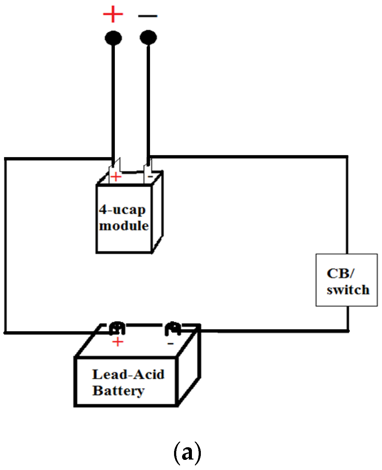
Figure 6.
Battery-biased parallel connection: (a) connection diagram; (b) test results; (c) simulation results.
Figure 6.
Battery-biased parallel connection: (a) connection diagram; (b) test results; (c) simulation results.


Figure 7.
Ultracapacitor-biased connection: (a) connection diagram; (b) results; (c) simulation results.
Figure 7.
Ultracapacitor-biased connection: (a) connection diagram; (b) results; (c) simulation results.


Figure 8.
Balanced parallel connection: (a) connection diagram; (b) test results; (c) simulation results.
Figure 8.
Balanced parallel connection: (a) connection diagram; (b) test results; (c) simulation results.


Figure 9.
Cranking current sharing as a function of ultracapacitor branch resistance keeping battery branch resistance constant.
Figure 9.
Cranking current sharing as a function of ultracapacitor branch resistance keeping battery branch resistance constant.

Figure 10.
Cranking current sharing as a function of battery branch resistance.

Figure 11.
Pulsed power profile defined in the JSR Micro study.

Figure 12.
Lead acid battery electrical circuit equivalent model.

Figure 13.
BSF as a function of BLF.

Figure 14.
HIF curves for a number of BSF values.

Figure 15.
CCF versus duty cycle for different values of BSF.

Figure 16.
(a). Current and voltage waveforms for a capacity measurement test; (b) current and voltage waveforms for a battery charging event.
Figure 16.
(a). Current and voltage waveforms for a capacity measurement test; (b) current and voltage waveforms for a battery charging event.

Figure 17.
Battery alone capacity versus cranking events with exponential extrapolation.

Figure 18.
Hybrid battery capacity versus cranking events with exponential extrapolation.


Table 1.
Engine cranking requirements for a number of car models [2].
Table 1.
Engine cranking requirements for a number of car models [2].
| Car Make | Year | Engine Size | Cranking Voltage | Cranking Current | Maximum Cranking Power | Cranking Energy |
|---|---|---|---|---|---|---|
| Toyota Solara | 2002 | 3.0 L | 8.3 V | 457 A | 4.2 kW | 1.7 kJ |
| Buick | 1998 | 3.1 L | 8.4 V | 462 A | 4.54 kW | 1.8 kJ |
| Ford Focus | 2013 | 2.0 L | 9.3 V | 452 A | 4.74 kW | 1.88 kJ |
| Saturn Vue | 2004 | 2.24 L | 7 V | 455 A | 3.52 kW | 1.27 kJ |
| Honda Civic | 2011 | 1.8 L | 7.7 V | 437 A | 3.4 kW | 1.08 kJ |
| Audi V6 | 1996 | 2.8 L | 9.84 V | 736 A | 7.36 kW | 1.67 kJ |
Table 2.
Cranking aging parameters.
| BLF | BSF | HIF | CCF | ECF | PPF | |
|---|---|---|---|---|---|---|
| Battery alone cold | 0.995 | 0.866 | NA | NA | NA | NA |
| Hybrid ESS cold | 0.55 | 0.197 | 4.4 | 14.99 | 13.9 | 0.59 |
| Battery alone warm | 0.978 | 0.743 | NA | NA | NA | NA |
| Hybrid ESS warm | 0.443 | 0.145 | 5.12 | 8.23 | 7.5 | 0.47 |
Table 3.
Capacity measurement results.
| Step No. | Capacity of Battery Alone | Capacity of Hybrid Battery |
|---|---|---|
| Step 0 | 28.22 Ah | 28.36 Ah |
| Step 1 | 25.56 Ah | 26.80 Ah |
| Step 2 | 25.11 Ah | 25.80 Ah |
| Step 3 | 24.96 Ah | 25.79 Ah |
| Step 4 | 24.86 Ah | 25.70 Ah |
| Step 5 | 22.70 Ah | 25.25 Ah |
| Step 6 | 25.98 Ah | 26.96 Ah |
| Step 7 | 22.80 Ah | 24.75 Ah |
| Step 8 | 22.39 Ah | 24.66 Ah |
| Step 9 | 21.89 Ah | 24.32 Ah |
| Step 10 | 21.28 Ah | 24.9 Ah |
Disclaimer/Publisher’s Note: The statements, opinions and data contained in all publications are solely those of the individual author(s) and contributor(s) and not of MDPI and/or the editor(s). MDPI and/or the editor(s) disclaim responsibility for any injury to people or property resulting from any ideas, methods, instructions or products referred to in the content. |
© 2023 by the authors. Licensee MDPI, Basel, Switzerland. This article is an open access article distributed under the terms and conditions of the Creative Commons Attribution (CC BY) license (https://creativecommons.org/licenses/by/4.0/).
Share and Cite
MDPI and ACS Style
Manla, E.; Nasiri, A. Age Estimation of a Hybrid Energy Storage System for Vehicular Start–Stop. Energies 2023, 16, 623. https://0-doi-org.brum.beds.ac.uk/10.3390/en16020623
AMA Style
Manla E, Nasiri A. Age Estimation of a Hybrid Energy Storage System for Vehicular Start–Stop. Energies. 2023; 16(2):623. https://0-doi-org.brum.beds.ac.uk/10.3390/en16020623
Chicago/Turabian StyleManla, Emad, and Adel Nasiri. 2023. "Age Estimation of a Hybrid Energy Storage System for Vehicular Start–Stop" Energies 16, no. 2: 623. https://0-doi-org.brum.beds.ac.uk/10.3390/en16020623
Note that from the first issue of 2016, this journal uses article numbers instead of page numbers. See further details here.