
Designing Hydrogen Recirculation Ejectors for Proton Exchange Membrane Fuel Cell Systems

1
School of Energy and Power Engineering, Xi’an Jiaotong University, Xi’an 710049, China
2
State Key Laboratory of Ultiphase Flow in Power Engineering, Xi’an Jiaotong University, Xi’an 710049, China
*
Author to whom correspondence should be addressed.
Energies 2023, 16(3), 1201; https://0-doi-org.brum.beds.ac.uk/10.3390/en16031201
Submission received: 20 December 2022
/
Revised: 18 January 2023
/
Accepted: 19 January 2023
/
Published: 21 January 2023
(This article belongs to the Special Issue Advanced Research on High-Energy Performance Compressors)
Abstract
:The proton exchange membrane fuel cell (PEMFC) is a promising device in the fields of power generation, energy storage, aerospace, and public transportation. The hydrogen recirculation ejector with the advantages of low cost, high durability, and no parasitic power is the key component of PEMFC systems. However, it is challenging to design a hydrogen recirculation ejector to cover the wide operating conditions of PEMFC systems. In order to design an ejector for fuel cell systems, a comprehensive understanding of ejector research is required. Consequently, the state-of-the-art research work on the hydrogen recirculation ejector is analyzed, including characteristics of the ejector in PEM fuel cell systems, geometry design and optimization, different types of ejectors and a comparison between them, and system integration and control. Through a comprehensive analysis of ejectors, further research suggestions on designing high-performance ejectors are presented.
1. Introduction
In recent years, the energy shortage has become more and more severe due to environmental, political, and demographic issues. Hydrogen energy and fuel cell technologies are becoming a research hotspot to alleviate energy shortages [1,2]. The proton exchange membrane fuel cell (PEMFC) can convert hydrogen energy into electricity with zero-emission. Due to its advantages of mobility, a fast startup, and modularity, it is promising in the fields of power generation, energy storage, aerospace, and public transportation [3]. However, fuel cells have not been widely used due to high manufacturing costs and durability issues [4,5].
At present, the main application field of PEM fuel cells is automobiles, especially high-power heavy-duty trucks [6]. The high-power fuel cell systems with a rated power of more than 100 kW are the focus of research and market development. A compact and highly integrated design is a critical requirement in the development of high-power systems. The PEM fuel cell system generally contains several subsystems including hydrogen supply, air supply, and thermal management [7,8]. The stable and efficient operation of each subsystem is necessary to ensure the high efficiency and long life of the fuel cell stack.
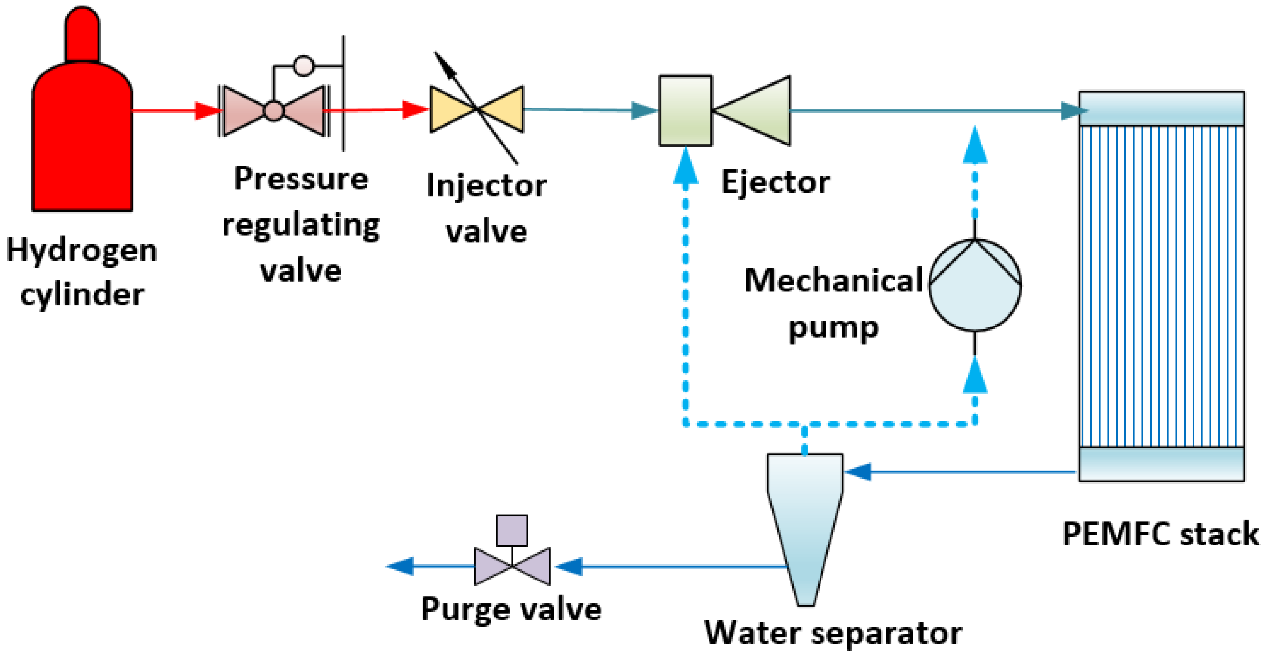
The mechanical pump and ejector are used to recycle the unconsumed hydrogen in the hydrogen supply subsystem, as seen in Figure 1. Popular mechanical pumps include the Roots pump [9], claw pump [10], and scroll pump [11]. The mechanical pump can adapt to different stack powers by adjusting the pump rotational speed. However, sealing, lubrication, and vibration issues reduce the durability of mechanical pumps [12]. The ejector is a kind of special booster that compresses the low-pressure secondary flow by the Venturi effect of the high-velocity primary flow. Compared to a hydrogen pump, the ejector has unique advantages because of its simple structure, low manufacturing cost, no moving parts, high durability, and no parasitic power consumption [13,14]. Therefore, both the mechanical pump and the ejector have their advantages and disadvantages. However, with the development of high-power fuel cell systems, the ejector will be more and more worthy of attention. Moreover, a combination of hydrogen pumps and ejectors can be adopted for super high-power systems, such as over 200 kW systems [15].
The operational characteristics of PEMFC systems pose great challenges to the design of the ejector [13]. The velocity of the primary flow at the nozzle outlet is relatively large under high power conditions so that the secondary flow is entrained by the primary flow with strong shear force [16]. Two fluids are mixed in the mixing chamber and they then flow into the diffuser with a pressure lift. However, when the primary mass flow rate is small, the ejector cannot induce the secondary flow because of the low velocity of the primary flow. Unfortunately, the stack power of a fuel cell system varies in a wide range [17]. The mass flow rate of the primary flow decreases with the decrease in the stack power. The entrainment performance of the ejector is poor under low stack powers.
In order to design an ejector suitable for PEM fuel cell systems with wide operating conditions, a comprehensive understanding of the challenges and difficulties faced by ejector research is necessary. The recent research work on the ejector for the PEM fuel cell system is analyzed, mainly including the characteristics of the ejector in PEM fuel cell systems, geometry design and optimization, different types of ejectors and a comparison between them, and system integration and control. Through a comprehensive analysis of the current research progress, further research suggestions are given.
2. Characteristics of the Ejector in PEM Fuel Cell Systems
Figure 2 shows a typical ejector-driven hydrogen recirculation of PEM fuel cell systems. The primary flow of the ejector is high-purity hydrogen from high-pressure hydrogen cylinders. The role of the injector valve is to adjust the mass flow rate of the primary flow according to the power of the fuel cell stack. The hydrogen supplied by the ejector will not be completely consumed in the fuel cell anode. Hence, the rest of the hydrogen is discharged from the anode outlet of the stack. The flow velocity increases after the primary flow through the primary nozzle. The maximum Mach number is up to 2.5 at the primary nozzle exit [17]. The high-velocity flow is turbulent and the turbulent Reynolds number is as high as 10,000. The momentum of the primary flow is transferred to the secondary flow, accelerating the secondary flow. The two flows are then further mixed in the mixing chamber and finally enter the diffuser when the pressure rises.
A significant characteristic of the ejector in PEMFC systems is the wide operating conditions. The primary flow rate of the ejector changes in a large range as stack power changes. Due to the fixed structure of the primary nozzle, the pressure of the primary flow decreases significantly with the decrease in the primary mass flow rate. The entrainment ratio is lower under lower primary flow pressures. The flow characteristics in the ejector will change largely in wide operating conditions [18]. Another critical characteristic of the ejector in PEMFC systems is the complex fluid medium. The fluid medium of the hydrogen recirculation ejector is the two-phase multi-species mixture in the PEM fuel cell system [19]. The general gas species include unconsumed hydrogen, nitrogen from the cathode, and water vapor. It is worth noting that liquid water also exists in the vast majority of cases.
The wide operating condition and complex fluid medium complicate the flow characteristics inside the ejector. The typical flow characteristics, as seen in Figure 3, include low separation [20], shock [21], flow instability [22], and two-phase flow [19]. These flow characteristics may affect the entrainment performance. For example, the presence of flow separation inside the ejector can cause energy dissipation, resulting in a lower entrainment ratio [20]. In addition, the shock and choking phenomenon inside the ejector are closely related to the entrainment performance [21].
The complicated flow characteristics can be investigated by the CFD methods. For example, Lamberts et al. [21] proved that the choking of the secondary flow limits the enhancement of the entrainment ratio by CFD techniques. Croquer et al. [22] indicated that flow instability and unsteady vortex occur in the ejector by using the large eddy simulation. Bodys et al. [23] and Navid Sharifi [24] developed a two-phase flow model based on homogeneous non-equilibrium condensation to investigate the effect of condensation phenomena. It was found that the two-phase CFD model was more in line with the actual physical situation.
The phase change and liquid behavior may affect the gas phase flow field and entrainment performance [25,26]. The phase transition inside the two-phase ejector for application in refrigeration systems and seawater desalination systems has been extensively studied [27,28]. Nevertheless, few studies on the phase change characteristics are conducted for the hydrogen recirculation ejector in fuel cell systems. The two-phase flow and phase transition phenomena in the hydrogen recirculation ejectors may be quite different because the condensable components are just contained in the secondary flow but not in the primary flow. Consequently, characteristics of the two-phase flow and its effects on ejector performance are worth further study.
3. Geometry Design and Optimization
It is difficult for the fixed-geometry ejector to cover the wide operating conditions, which is the main reason for limiting the application of the ejector in the PEMFC system. The geometry design and optimization are critical to maximizing the entrainment performance [29]. However, the geometry design of the ejector is challenging because of the coupled effects of multiple geometric parameters, wide operating conditions, and complex fluid properties [30,31]. The performance indicators of the ejector in PEM fuel cell systems are the hydrogen entrainment ratio (ERH2) and range coefficient (Reje), as defined in Equations (1) and (2), respectively. A larger Reje means that the ejector can cover a wider power range of the PEMFC systems. Generally, the Reje of a conventional ejector in PEMFC systems is about 65–80% [12].
where is the hydrogen entrainment ratio, ms,H2 is the hydrogen mass flow rate of the secondary flow, mp is the mass flow rate of the primary flow, Reje is the range coefficient, is the peak power of the fuel cell stack, Pmax and Pmin are the maximum and minimum operating powers, respectively.
Figure 4 shows the schematic diagram of the main geometrical parameters. It is noted that the primary nozzle of the ejector in fuel cell systems is commonly convergent [12,13]. This is because the entrainment ratio of the ejector with a convergent nozzle is higher than that with a convergent-divergent nozzle under low stack powers [17]. The ejector with a convergent nozzle can adapt to the wider operating conditions of PEMFC systems.
The influence of these geometric parameters is different under various operating conditions. Firstly, two critical parameters including the primary nozzle throat diameter (Dt) and the mixing chamber diameter (Dm) can make a significant effect on the ejector’s performance under any conditions. This is because the throat diameter can limit the primary mass flow rate, while the mixing chamber diameter limits the secondary mass flow rate. Carrillo et al. [32] compared several geometric parameters of the ejector by a multi-objective optimization algorithm and proved that the entrainment ratio changed significantly with Dt and Dm. Hence, these two parameters must be designed carefully under any conditions. Moreover, the operating temperature of the ejector can vary widely, especially in cold climates where the temperature difference between the inside and outside of the ejector may reach 100 °C. The size of Dt and Dm may change due to material deformation under large temperature differences. The effects of machining accuracy and material deformation are worthy of study.
In addition, the nozzle position (NXP), the parallel mixing chamber length (Lm), and the angle and length of the converging mixing chamber (αc and Lc) could affect the mixing process of the primary and secondary flow [33,34]. The optimal values of these parameters are also related to the mixing chamber diameter. In addition, the angle and length of the diffuser (αd and Ld) can also have a remarkable effect. The improper design of the two parameters could lead to energy dissipation in the diffuser. Nevertheless, it should be noted that the influence of these parameters is closely related to the operating conditions. The variation law of the geometric parameters is even the opposite in different research works. This is because the operating conditions and structural parameter ranges are different in different works. Consequently, a common optimal range of the geometric parameters cannot be given for different ejectors under different operating conditions. The geometric parameters of the ejector should be optimized based on the actual working conditions.
The abovementioned geometric parameters could have a certain degree of influence on the ejector performance under different working conditions. It is difficult to propose an efficient optimal design method for the optimal design of the ejector to evaluate all geometric parameters. Pei et al. [34] used the single-parameter optimization method to design the parameters of an ejector including Dt, Dm, Lm, and NXP for a 10 kW fuel cell system. Similarly, a hydrogen recirculation ejector for an 80 kW fuel cell system was designed by Ma et al. [35] using single-factor analysis on the design of four key geometric parameters including Dt, Dm, NXP, and the secondary inlet diameter. These optimization methods may be not efficient to design a high-performance hydrogen recirculation ejector. Consequently, the design methods of the ejector for wide-power operating conditions, such as machine learning, neural network, and other advanced optimization methods, are worth studying.
4. Different Types of Ejectors and Comparison
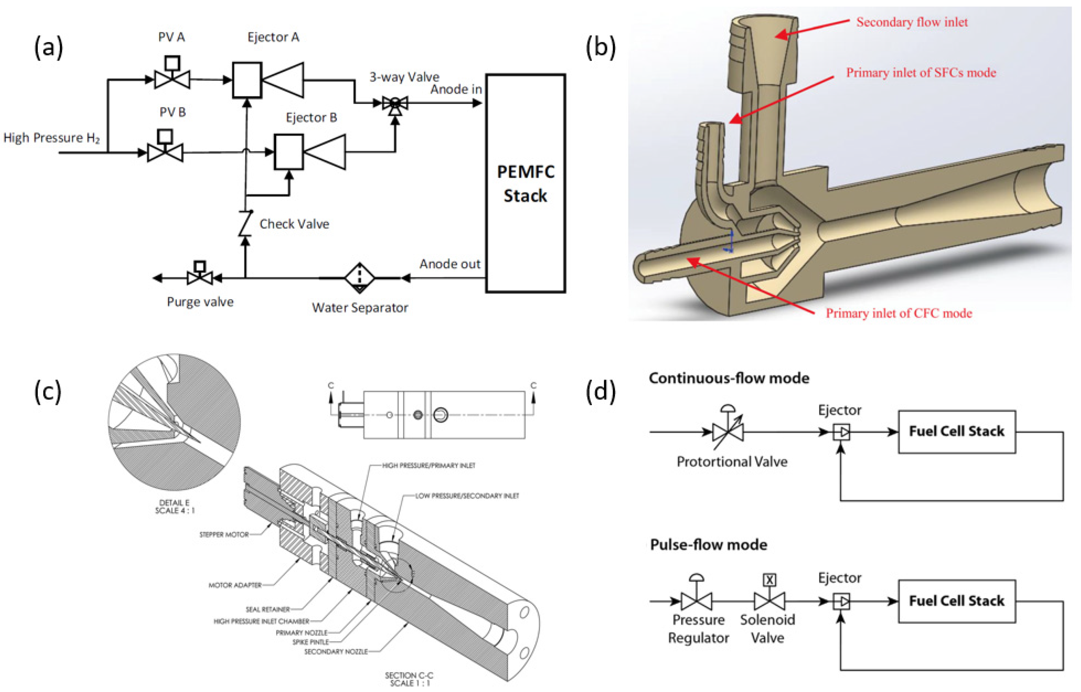
The conventional ejector cannot fit wide operating conditions, especially for high-power stacks. To widen the applicable power range of ejectors, more kinds of ejectors have been designed, including parallel ejectors, multi-nozzle ejectors, adjustable ejectors, and pulse ejectors, as seen in Figure 5.
The parallel ejector means using multiple ejectors in different power ranges [36]; for example, the ejector with a larger throat diameter works in the high-power range, while the ejector with a lower throat diameter works in the low-power range, as seen in Figure 5a [37]. Furthermore, the multi-nozzle ejector is an improved design of the multiple ejectors. A common mixing chamber is employed in the multi-nozzle to reduce volume, as shown in Figure 5b [38]. The number of nozzles can be changed according to the power range, such as the ejector with twin nozzles [39] and the ejector with four nozzles [40]. Although multiple and multi-nozzle ejectors are useful for a wide power range, the entrainment performance may fluctuate during ejector switching. The control methods of parallel and multi-nozzle ejectors are bound to be critical issues when trying to switch the nozzle.
Figure 5c [41] shows the adjustable nozzle ejector where an adjustable spindle is used to change the fluid flow area of the primary nozzle. The effective fluid flow area can be decreased, and thereby the primary flow velocity is increased to improve the entrainment ratio. The performance improvement of the adjustable ejector was obvious for the application in fuel cell systems [42,43]. However, it should be noted that the sealing problems are troubling due to moving nozzles. In fact, the sealing of hydrogen gas is a big challenge for moving parts in hydrogen supply devices. Moreover, the control strategy may be more complicated for the adjustable ejector compared with the conventional ejector.
The pulse ejector means that the primary flow is pulsed because of the action of the hydrogen injector. The PEMFC stack might work efficiently under low power conditions by using the pulsed flow mode, as shown in Figure 5d [44]. However, the fluid flow characteristics inside the pulse ejector are rarely studied, and the working principle of the pulse flow is not yet clear up to now. Furthermore, from an engineering application point of view, the durability of the solenoid valve can be detracted by frequent opening and closing. In addition, the related control strategy of the pulsed primary flow also needs further study.
In summary, these different types of ejectors can be applied to a wider range of operating conditions for PEMFC systems. The comparisons of different types of ejectors are concluded in Table 1. These unconventional ejectors have better adaptability to wide conditions. However, new problems in terms of manufacturing cost, control methods, and durability for these ejectors need to be solved.

5. System Integration and Control
In addition to the ejector, there are other important components in the hydrogen supply system, including the hydrogen injector, the gas-water separator, and the purge valve (see Figure 1). The ejector performance might be greatly affected by the action of other components [45]. Firstly, the hydrogen injector valve can adjust the primary mass flow rate. Under dynamic conditions, the hydrogen supply capacity and response speed of the hydrogen injector valve affect the ejector performance [46]. Secondly, the purge valve that is used to purge accumulative nitrogen and liquid water can affect the composition of the secondary flow [47]. The higher the concentration of nitrogen in the secondary flow, the lower the entrainment ratio of the ejector [48]. The experimental study by Wang et al. [49] showed that obvious pressure fluctuation occurred in the ejector under the purge of nitrogen and liquid water. Moreover, the design of the separator and recirculation pipeline could affect the pressure loss [50]. In short, other components can have a non-negligible impact on the ejector performance. The design and control methods of these components and their effects should be considered carefully when designing and developing the hydrogen recirculation ejector.
Effective control techniques are required to ensure high ejector performance over the whole power range of PEMFC systems [51]. Currently, there are various control strategies suitable for the ejector-driven hydrogen supply system. In engineering applications, the classical PID control method is still the most popular strategy. Furthermore, some novel control methods, such as the discrete control strategy [52] and the fuzzy control method [53], were studied in the hydrogen recirculation subsystem. The stability, accuracy, and rapidity of different control methods may be different. It needs to be selected according to the dynamic characteristics and working range of the customized hydrogen recirculation ejector.
The control strategy of the ejector should not only focus on the improvement of the ejector performance. More importantly, the fuel cell stack should be guaranteed to have high efficiency and long life under dynamic conditions [54]. The performance of the fuel cell stack is of more concern than the ejector performance. The control of the ejector should be combined with the control of other components [55,56]. Additionally, the operation of the air subsystem can affect the hydrogen control strategy [57]. Hence, the control strategy of the ejector should be designed from the perspective of the whole system, and should not be a one-sided pursuit of the ejector performance. In general, the system integration and control strategy are of great importance to the performance of the ejector and other components. Nevertheless, much of the public research on ejector control mainly involved simulation studies and a few experimental tests for low-power fuel cell systems. Therefore, more experimental research on the integration and control in high-power PEMFC systems is expected in the future.
6. Summary and Outlook
The cost and durability of the PEM fuel cell systems hinder commercial application. The hydrogen recirculation ejector is a promising device, especially for high-power fuel cell systems. However, designing an ejector that can cover a wide operating range of PEMFC systems is a big challenging problem. Consequently, a great number of studies on characteristics of the ejector in PEM fuel cell systems, structure design and optimization, different types of ejectors and a comparison between them, and system integration and control have been carried out.
Two significant characteristics of the ejector in PEM fuel cell systems are wide operating conditions and the complex fluid medium. The fluid flow characteristics in the hydrogen recirculation ejector are thereby more complicated. Research on phase transition phenomena in hydrogen recirculation ejectors is still scarce. More research on two-phase flow characteristics and their effects on hydrogen recirculation ejectors and fuel cell stacks is necessary.
The geometry design and optimization are challenging due to multiple geometric parameters having a remarkable influence on the ejector performance under different working conditions. The popular single-factor optimization method has the disadvantage of a heavy workload. Thus, more advanced optimization methods are absolutely necessary to design the ejector. On the other hand, some different types of ejectors are proposed for PEMFC systems, including parallel ejectors, multi-nozzle ejectors, variable-nozzle ejectors, and pulse ejectors. However, these ejectors also bring new challenges in terms of cost, control, and manufacturing. The ejector should be customized for the PEMFC systems with different operating conditions.
The ejector performance could be affected by other components including the injector, gas-water separator, and purge valve. The design and control methods of these components and their effects on the ejector should be considered carefully. Moreover, efficient control techniques are required to ensure stable ejector performance under dynamic operating conditions.
In summary, with the further development and application of fuel cells, the ejector will definitely be studied more comprehensively and deeply. A more in-depth analysis from the perspective of fluid mechanics is necessary for the study of complex fluid flow characteristics inside the ejector. Advanced mathematical optimization methods are significant for the further design and optimization of the ejector. More studies on control theory can promote the efficient integration and control of the ejector. Therefore, multi-disciplinary intersection research is indispensable for the design and application of ejectors in fuel cell systems.
Author Contributions
Conceptualization, J.F. and J.H.; methodology, J.F.; investigation, J.H. and Z.P.; resources, J.F. and X.P.; writing—original draft preparation, J.F. and J.H.; writing—review and editing, J.F. and J.H.; supervision, X.P.; funding acquisition, J.F. All authors have read and agreed to the published version of the manuscript.
Funding
This research was funded by the National Key Research and Development Program of China [Grant No. 2021YFB2500500].
Data Availability Statement
Data is contained within the article.
Acknowledgments
The authors would like to acknowledge the support of the National Key Research and Development Program of China [Grant No. 2021YFB2500500].
Conflicts of Interest
The authors declare no conflict of interest.
References
- Jiao, K.; Xuan, J.; Du, Q.; Bao, Z.; Xie, B.; Wang, B.; Zhao, Y.; Fan, L.; Wang, H.; Hou, Z.; et al. Designing the next generation of proton-exchange membrane fuel cells. Nature 2021, 595, 361–369. [Google Scholar] [CrossRef]
- Bethoux, O. Hydrogen Fuel Cell Road Vehicles and Their Infrastructure: An Option towards an Environmentally Friendly Energy Transition. Energies 2020, 13, 6132. [Google Scholar] [CrossRef]
- Fan, L.; Tu, Z.; Chan, S.H. Recent development of hydrogen and fuel cell technologies: A review. Energy Rep. 2021, 7, 8421–8446. [Google Scholar] [CrossRef]
- Zhao, J.; Li, X. A review of polymer electrolyte membrane fuel cell durability for vehicular applications: Degradation modes and experimental techniques. Energy Convers. Manag. 2019, 199, 112022. [Google Scholar] [CrossRef]
- Wang, Y.; Ruiz Diaz, D.F.; Chen, K.S.; Wang, Z.; Adroher, X.C. Materials, technological status, and fundamentals of PEM fuel cells—A review. Mater. Today 2020, 32, 178–203. [Google Scholar] [CrossRef]
- Liu, F.; Mauzerall, D.L.; Zhao, F.; Hao, H. Deployment of fuel cell vehicles in China: Greenhouse gas emission reductions from converting the heavy-duty truck fleet from diesel and natural gas to hydrogen. Int. J. Hydrogen Energy 2021, 46, 17982–17997. [Google Scholar] [CrossRef]
- Hu, D.; Wang, Y.; Li, J.; Yang, Q.; Wang, J. Investigation of optimal operating temperature for the PEMFC and its tracking control for energy saving in vehicle applications. Energy Convers. Manag. 2021, 249, 114842. [Google Scholar] [CrossRef]
- Grimm, M.; Hellmann, M.; Kemmer, H.; Kabelac, S. Water Management of PEM Fuel Cell Systems Based on the Humidity Distribution in the Anode Gas Channels. Fuel Cells 2020, 20, 477–486. [Google Scholar] [CrossRef]
- Feng, J.; Xing, L.; Wang, B.; Wei, H.; Xing, Z. Effects of Working Fluids on the Performance of a Roots Pump for Hydrogen Recirculation in a PEM Fuel Cell System. Appl. Sci. 2020, 10, 8069. [Google Scholar] [CrossRef]
- Gu, P.; Xing, L.; Wang, Y.; Feng, J.; Peng, X. Transient flow field and performance analysis of a claw pump for FCVs. Int. J. Hydrogen Energy 2021, 46, 984–997. [Google Scholar] [CrossRef]
- Feng, J.; Zhang, Q.; Hou, T.; Peng, X. Dynamics characteristics analysis of the oil-free scroll hydrogen recirculating pump based on multibody dynamics simulation. Int. J. Hydrogen Energy 2021, 46, 5699–5713. [Google Scholar]
- Han, J.; Feng, J.; Chen, P.; Liu, Y.; Peng, X. A review of key components of hydrogen recirculation subsystem for fuel cell vehicles. Energy Convers. Manag. X 2022, 15, 100265. [Google Scholar] [CrossRef]
- Liu, Y.; Tu, Z.; Chan, S.H. Applications of ejectors in proton exchange membrane fuel cells: A review. Fuel Process. Technol. 2020, 214, 106683. [Google Scholar] [CrossRef]
- Tashtoush, B.M.; Al-Nimr, M.A.; Khasawneh, M.A. A comprehensive review of ejector design, performance, and applications. Appl. Energy 2019, 240, 138–172. [Google Scholar] [CrossRef]
- Han, J.; Kong, X.; Feng, J.; Peng, X. Performance Analysis of Hydrogen Recirculation System of High Power Fuel Cell Vehicles. Qiche Gongcheng/Automot. Eng. 2022, 44, 1–7. [Google Scholar]
- Besagni, G.; Cristiani, N.; Croci, L.; Guédon, G.R.; Inzoli, F. Computational fluid-dynamics modelling of supersonic ejectors: Screening of modelling approaches, comprehensive validation and assessment of ejector component efficiencies. Appl. Therm. Eng. 2021, 186, 116431. [Google Scholar] [CrossRef]
- Feng, J.; Han, J.; Hou, T.; Peng, X. Performance analysis and parametric studies on the primary nozzle of ejectors in proton exchange membrane fuel cell systems. Energy Sources Part A Recovery Util. Environ. Eff. 2020. [Google Scholar] [CrossRef]
- Yadav, S.K.; Murari Pandey, K.; Gupta, R. Recent advances on principles of working of ejectors: A review. Mater. Today Proc. 2021, 45, 6298–6305. [Google Scholar] [CrossRef]
- Han, J.; Feng, J.; Peng, X. Phase change characteristics and their effect on the performance of hydrogen recirculation ejectors for PEMFC systems. Int. J. Hydrogen Energy 2022, 47, 1144–1156. [Google Scholar] [CrossRef]
- Han, Y.; Wang, X.; Sun, H.; Zhang, G.; Guo, L.; Tu, J. CFD simulation on the boundary layer separation in the steam ejector and its influence on the pumping performance. Energy 2019, 167, 469–483. [Google Scholar] [CrossRef]
- Lamberts, O.; Chatelain, P.; Bartosiewicz, Y. Numerical and experimental evidence of the Fabri-choking in a supersonic ejector. Int. J. Heat Fluid Flow 2018, 69, 194–209. [Google Scholar] [CrossRef]
- Croquer, S.; Lamberts, O.; Poncet, S.; Moreau, S.; Bartosiewicz, Y. Large Eddy Simulation of a supersonic air ejector. Appl. Therm. Eng. 2022, 209, 118177. [Google Scholar] [CrossRef]
- Bodys, J.; Smolka, J.; Palacz, M.; Haida, M.; Banasiak, K. Non-equilibrium approach for the simulation of CO2 expansion in two-phase ejector driven by subcritical motive pressure. Int. J. Refrig. 2020, 114, 32–46. [Google Scholar] [CrossRef]
- Sharifi, N. Numerical study of non-equilibrium condensing supersonic steam flow in a jet-pump based on supersaturation theory. Int. J. Mech. Sci. 2020, 165, 105221. [Google Scholar] [CrossRef]
- Tang, Y.; Liu, Z.; Li, Y.; Wu, H.; Zhang, X.; Yang, N. Visualization experimental study of the condensing flow regime in the transonic mixing process of desalination-oriented steam ejector. Energy Convers. Manag. 2019, 197, 111849. [Google Scholar] [CrossRef]
- Wang, Y.; Pellerin, M.; Mohanty, P.; Sengupta, S. Investigation of the Flow Phenomenon Inside Gas Ejectors With Moist Gas Entrainment. J. Therm. Sci. Eng. Appl. 2017, 9, 0110051. [Google Scholar] [CrossRef]
- Ringstad, K.E.; Allouche, Y.; Gullo, P.; Ervik, Å.; Banasiak, K.; Hafner, A. A detailed review on CO2 two-phase ejector flow modeling. Therm. Sci. Eng. Prog. 2020, 20, 100647. [Google Scholar] [CrossRef]
- Wen, C.; Ding, H.; Yang, Y. Performance of steam ejector with nonequilibrium condensation for multi-effect distillation with thermal vapour compression (MED-TVC) seawater desalination system. Desalination 2020, 489, 114531. [Google Scholar] [CrossRef]
- Zheng, J.; Hou, Y.; Tian, Z.; Jiang, H.; Chen, W. Simulation Analysis of Ejector Optimization for High Mass Entrainment under the Influence of Multiple Structural Parameters. Energies 2022, 15, 7058. [Google Scholar] [CrossRef]
- Zhang, K.; Zhang, Z.; Han, Y.; Gu, Y.; Qiu, Q.; Zhu, X. Artificial neural network modeling for steam ejector design. Appl. Therm. Eng. 2022, 204, 117939. [Google Scholar] [CrossRef]
- Barta, R.B.; Dhillon, P.; Braun, J.E.; Ziviani, D.; Groll, E.A. Design and optimization strategy for ejectors applied in refrigeration cycles. Appl. Therm. Eng. 2021, 189, 116682. [Google Scholar] [CrossRef]
- Expósito Carrillo, J.A.; Sánchez De La Flor, F.J.; Salmerón Lissén, J.M. Single-phase ejector geometry optimisation by means of a multi-objective evolutionary algorithm and a surrogate CFD model. Energy 2018, 164, 46–64. [Google Scholar] [CrossRef]
- Metin, C.; Gök, O.; Atmaca, A.U.; Erek, A. Numerical investigation of the flow structures inside mixing section of the ejector. Energy 2019, 166, 1216–1228. [Google Scholar] [CrossRef]
- Pei, P.; Ren, P.; Li, Y.; Wu, Z.; Chen, D.; Huang, S.; Jia, X. Numerical studies on wide-operating-range ejector based on anodic pressure drop characteristics in proton exchange membrane fuel cell system. Appl. Energy 2019, 235, 729–738. [Google Scholar] [CrossRef]
- Ma, T.; Cong, M.; Meng, Y.; Wang, K.; Zhu, D.; Yang, Y. Numerical studies on ejector in proton exchange membrane fuel cell system with anodic gas state parameters as design boundary. Int. J. Hydrogen Energy 2021, 46, 38841–38853. [Google Scholar] [CrossRef]
- Gullo, P.; Hafner, A.; Banasiak, K.; Minetto, S.; Kriezi, E. Multi-Ejector Concept: A Comprehensive Review on its Latest Technological Developments. Energies 2019, 12, 406. [Google Scholar] [CrossRef] [Green Version]
- Chen, L.; Xu, K.; Yang, Z.; Yan, Z.; Dong, Z. Optimal Design and Operation of Dual-Ejector PEMFC Hydrogen Supply and Circulation System. Energies 2022, 15, 5427. [Google Scholar] [CrossRef]
- Han, J.; Feng, J.; Hou, T.; Peng, X. Performance investigation of a multi-nozzle ejector for proton exchange membrane fuel cell system. Int. J. Energ. Res. 2021, 45, 3031–3048. [Google Scholar] [CrossRef]
- Song, Y.; Wang, X.; Wang, L.; Pan, F.; Chen, W.; Xi, F. A twin-nozzle ejector for hydrogen recirculation in wide power operation of polymer electrolyte membrane fuel cell system. Appl. Energy 2021, 300, 117442. [Google Scholar] [CrossRef]
- Xue, H.; Wang, L.; Zhang, H.; Jia, L.; Ren, J. Design and investigation of multi-nozzle ejector for PEMFC hydrogen recirculation. Int. J. Hydrogen Energy 2020, 45, 14500–14516. [Google Scholar] [CrossRef]
- Brunner, D.A.; Marcks, S.; Bajpai, M.; Prasad, A.K.; Advani, S.G. Design and characterization of an electronically controlled variable flow rate ejector for fuel cell applications. Int. J. Hydrogen Energy 2012, 37, 4457–4466. [Google Scholar] [CrossRef]
- Jenssen, D.; Berger, O.; Krewer, U. Improved PEM fuel cell system operation with cascaded stack and ejector-based recirculation. Appl. Energy 2017, 195, 324–333. [Google Scholar] [CrossRef]
- Baba, S.; Takahashi, S.; Kobayashi, N.; Hirano, S. Performance of anodic recirculation by a variable flow ejector for a solid oxide fuel cell system under partial loads. Int. J. Hydrogen Energy 2020, 45, 10039–10049. [Google Scholar] [CrossRef]
- Hwang, J. Passive hydrogen recovery schemes using a vacuum ejector in a proton exchange membrane fuel cell system. J. Power Sources 2014, 247, 256–263. [Google Scholar] [CrossRef]
- Kuo, J.; Hsieh, C. Numerical investigation into effects of ejector geometry and operating conditions on hydrogen recirculation ratio in 80 kW PEM fuel cell system. Energy 2021, 233, 121100. [Google Scholar] [CrossRef]
- Kuo, J.; Jiang, W.; Li, C.; Hsu, T. Numerical investigation into hydrogen supply stability and I-V performance of PEM fuel cell system with passive Venturi ejector. Appl. Therm. Eng. 2020, 169, 114908. [Google Scholar] [CrossRef]
- Liu, Z.; Chen, J.; Liu, H.; Yan, C.; Hou, Y.; He, Q.; Zhang, J.; Hissel, D. Anode purge management for hydrogen utilization and stack durability improvement of PEM fuel cell systems. Appl. Energy 2020, 275, 115110. [Google Scholar] [CrossRef]
- Hailun, Z.; Sun, W.; Xue, H.; Sun, W.; Wang, L.; Jia, L. Performance analysis and prediction of ejector based hydrogen recycle system under variable proton exchange membrane fuel cell working conditions. Appl. Therm. Eng. 2021, 197, 117302. [Google Scholar] [CrossRef]
- Wang, X.; Lu, Y.; Zhang, B.; Liu, J.; Xu, S. Experimental analysis of an ejector for anode recirculation in a 10 kW polymer electrolyte membrane fuel cell system. Int. J. Hydrogen Energy 2022, 47, 1925–1939. [Google Scholar] [CrossRef]
- Han, J.; Feng, J.; Hou, T.; Chen, W.; Peng, X. Numerical and experimental study on gas-water separators for a PEMFC system. Int. J. Green Energy 2021, 18, 490–502. [Google Scholar] [CrossRef]
- Steinberger, M.; Geiling, J.; Oechsner, R.; Frey, L. Anode recirculation and purge strategies for PEM fuel cell operation with diluted hydrogen feed gas. Appl. Energy 2018, 232, 572–582. [Google Scholar] [CrossRef]
- Nikiforow, K.; Pennanen, J.; Ihonen, J.; Uski, S.; Koski, P. Power ramp rate capabilities of a 5 kW proton exchange membrane fuel cell system with discrete ejector control. J. Power Sources 2018, 381, 30–37. [Google Scholar] [CrossRef]
- Ye, X.; Zhang, T.; Chen, H.; Cao, J.; Chen, J. Fuzzy control of hydrogen pressure in fuel cell system. Int. J. Hydrogen Energy 2019, 44, 8460–8466. [Google Scholar] [CrossRef]
- He, H.; Quan, S.; Wang, Y. Hydrogen circulation system model predictive control for polymer electrolyte membrane fuel cell-based electric vehicle application. Int. J. Hydrogen Energy 2020, 45, 20382–20390. [Google Scholar] [CrossRef]
- Han, J.; Zhao, B.; Pang, Z.; Feng, J.; Peng, X. Transient characteristics investigation of the integrated ejector-driven hydrogen recirculation by multi-component CFD simulation. Int. J. Hydrogen Energy 2022, 47, 29053–29068. [Google Scholar] [CrossRef]
- Singer, G.; Gappmayer, G.; Macherhammer, M.; Pertl, P.; Trattner, A. A development toolchain for a pulsed injector-ejector unit for PEM fuel cell applications. Int. J. Hydrogen Energy 2022, 47, 23818–23832. [Google Scholar] [CrossRef]
- Yin, X.; Wang, X.; Wang, L.; Qin, B.; Liu, H.; Jia, L.; Cai, W. Cooperative control of air and fuel feeding for PEM fuel cell with ejector-driven recirculation. Appl. Therm. Eng. 2021, 199, 117590. [Google Scholar] [CrossRef]
Figure 1.
Schematic diagram of the hydrogen supply subsystem in a PEMFC system.

Figure 2.
Schematic diagram of a typical ejector-driven hydrogen recirculation of PEM fuel cell systems.
Figure 2.
Schematic diagram of a typical ejector-driven hydrogen recirculation of PEM fuel cell systems.

Figure 3.
Complicated flow characteristics in ejectors: (a) flow separation [20], (b) shock [21], (c) flow instability [22], and (d) two-phase flow [19].

Figure 4.
Schematic diagram of the ejector geometry.


Table 1.
Comparisons of different types of ejectors.
| Types | Adaptability to Wide Conditions | Control Method | Durability | Cost |
|---|---|---|---|---|
| Conventional ejector | ★ | ★★★ | ★★★ | ★★★ |
| Parallel ejector | ★★ | ★★ | ★★ | ★★ |
| Multi-nozzle ejector | ★★ | ★★ | ★★ | ★★ |
| Adjustable ejector | ★★★ | ★ | ★ | ★ |
| Pulse ejector | ★★ | ★ | ★★ | ★★ |
Disclaimer/Publisher’s Note: The statements, opinions and data contained in all publications are solely those of the individual author(s) and contributor(s) and not of MDPI and/or the editor(s). MDPI and/or the editor(s) disclaim responsibility for any injury to people or property resulting from any ideas, methods, instructions or products referred to in the content. |
© 2023 by the authors. Licensee MDPI, Basel, Switzerland. This article is an open access article distributed under the terms and conditions of the Creative Commons Attribution (CC BY) license (https://creativecommons.org/licenses/by/4.0/).
Share and Cite
MDPI and ACS Style
Feng, J.; Han, J.; Pang, Z.; Peng, X. Designing Hydrogen Recirculation Ejectors for Proton Exchange Membrane Fuel Cell Systems. Energies 2023, 16, 1201. https://0-doi-org.brum.beds.ac.uk/10.3390/en16031201
AMA Style
Feng J, Han J, Pang Z, Peng X. Designing Hydrogen Recirculation Ejectors for Proton Exchange Membrane Fuel Cell Systems. Energies. 2023; 16(3):1201. https://0-doi-org.brum.beds.ac.uk/10.3390/en16031201
Chicago/Turabian StyleFeng, Jianmei, Jiquan Han, Zihui Pang, and Xueyuan Peng. 2023. "Designing Hydrogen Recirculation Ejectors for Proton Exchange Membrane Fuel Cell Systems" Energies 16, no. 3: 1201. https://0-doi-org.brum.beds.ac.uk/10.3390/en16031201
Note that from the first issue of 2016, this journal uses article numbers instead of page numbers. See further details here.