
A Review on Methanol as a Clean Energy Carrier: Roles of Zeolite in Improving Production Efficiency
by
 and
and
Aubaid Ullah
1,
Nur Awanis Hashim
1,2,*,
Mohamad Fairus Rabuni
1,2 and
Mohd Usman Mohd Junaidi
1,2 1
Department of Chemical Engineering, Faculty of Engineering, Universiti Malaya, Kuala Lumpur 50603, Malaysia
2
Center for Separation Science and Technology, Faculty of Engineering, Universiti Malaya, Kuala Lumpur 50603, Malaysia
*
Author to whom correspondence should be addressed.
Energies 2023, 16(3), 1482; https://0-doi-org.brum.beds.ac.uk/10.3390/en16031482
Submission received: 4 January 2023
/
Revised: 19 January 2023
/
Accepted: 25 January 2023
/
Published: 2 February 2023
(This article belongs to the Special Issue Applications of Nanomaterials in Clean Energy)
Abstract
:Clean methanol can play an important role in achieving net zero emission targets by decarbonizing the energy and chemical sectors. Conventionally, methanol is produced by using fossil fuel as raw material, which releases a significant amount of greenhouse gases (GHGs) into the environment. Clean methanol, which is produced by hydrogen (H2) from renewable sources (green H2) and captured carbon dioxide (CO2), is totally free from the influence of fossil fuel. Due to its vast applications, clean methanol has potential to substitute for fossil fuels while preventing further GHGs emissions. This review addresses the feasibility of producing clean methanol from renewable resources, i.e., green H2 and captured CO2. Availability of these raw materials is the main factor involved in establishing the circular economy of methanol, therefore, their potential sources and the possible pathways to access these sources are also summarized. Renewable energy sources such as solar, wind and biomass should be utilized for producing green H2, while CO2 captured from air, and more likely from point emission sources, can be recycled to produce clean methanol. After producing methanol from CO2 and H2, the removal of by-product water by distillation is a big challenge due its high energy consumption. An alternative approach for this methanol-water separation is membrane technology, which is an energy saving option. Water-selective zeolite membranes can separate water post-synthesis, as well as during the synthesis. Production efficiency of methanol can be enhanced by utilizing zeolite membranes inside the methanol synthesis reactor. Furthermore, CO2 conversion as well as methanol selectivity, purity and yield can also be increased significantly by selectively removing by-product water using a zeolite membrane reactor.
1. Introduction
With technological advances, there is a constantly increasing demand for energy in all aspects of human life, including the power sector and the transportation, construction, and chemical industries, using mainly oil and coal fossil fuels [1,2,3]. However, the consumption of fossil fuel to meet energy demands has two major concerns, namely, continuous depletion due to the long life-cycle of regeneration, and strong environmental impact, including greenhouse gas (GHG) emissions, which contradicts the net zero carbon dioxide (CO2) emission target. As stated in the Paris Agreement (2015), the target was to control global temperature increment to be in the range of 1.5 to 2 °C from pre-industrial level for GHGs emissions monitoring [4,5,6,7]. Consequently, CO2 emissions should be decreased by 45% from 2010 to 2030, and net zero emissions reached by 2050 [8,9].
At present, there is a huge gap between the supply and demand regarding clean renewable energy, which is being fulfilled by carbon-intensive fossil fuels, resulting in increased GHG emissions [10]. Of late, a significant portion of world energy has been obtained from nuclear sources undergoing fission reaction, which is also considered to be clean-energy, but it comes with safety concerns and capital investment drawbacks. This scenario urges increased reliance on renewable energy resources such as solar, wind, hydro, geothermal and biomass and subsequently, their conversion into other forms of energy via clean processing routes [11]. Alternatively, it has been suggested that recycling of atmospheric CO2 could play an important role in reducing carbon footprints and providing essential carbon-based products [12,13]. Carbon capture and storage (CCS) during recycling of atmospheric CO2 has a negative systemic impact, as more energy needs to be put in the system; conversely, carbon capture and utilization (CCU) could improve the cost/benefit of products produced [14]. Successively, clean methanol is one of the products derived from captured CO2 that has a potential to decouple the supply of fossil fuels by fulfilling the daily demand of carbon-based products. Furthermore, clean methanol is produced by raw materials from renewable sources; it can play a role in achieving United Nations (UN) Sustainable Development Goals (SDGs) [15].
Conversion of atmospheric CO2 to clean methanol requires high levels of energy and hydrogen (H2) to activate the stable molecule of CO2 [16]. These demands must be satisfied by renewable sources in order to curb net GHG emissions to the atmosphere [17]. H2 (from renewable energy) itself is a precious fuel, having high energy content, but it is costly in terms of handling and storage; alternatively, it could be stored in the form of methanol, which is cheaper to manage. Utilization of methanol in various sectors of energy, transportation and chemical feedstock provides an inroad to store the renewable energy in a convenient and reliable form. Based on these positive potentials, clean methanol production has captured industrial attention. Recently, Cement Australia, an Australian company, has signed an agreement with Mitsubishi Gas Chemical Company to install green methanol production with the captured CO2 from their Gladstone cement plant and locally produced green H2 [18].
Heterogeneous catalysis is one of the industrially viable options for chemical reduction of CO2 to produce methanol [19]. This synthesis route produces methanol along with by-product water. Separation of methanol/water mixture after synthesis is mainly done by a distillation process which consumes a high portion of plant energy. This separation could be performed by a less energy-intensive membrane-based operation in order to save the plant’s energy and economy. Several membrane materials, including zeolite-based membrane, have been reported in the literature for this kind of separation [20,21,22]. Mahmood et al. prepared polymeric membrane based on sodium alginate (SA)/polyvinyl alcohol (PVA) for selectively removing water from a methanol-water mixture. The maximum operating temperature tested in their study was 60 °C, which suits best for post-synthesis methanol-water separation [23]. On contrary, separation of water directly from methanol synthesis requires thermally stable membranes at a high temperature (250 °C) [24]. Consequently, Kreethawate et al., prepared a ceramic-based zeolite membrane for methanol-water separation and achieved good performance at 175 °C [25]. Therefore, the zeolite membranes, due to their sufficient thermal stability, can be subject to high temperature applications, for example, in methanol synthesis [26,27].
Another important challenge in catalytic CO2 hydrogenation to methanol is limited CO2 conversion within current industrial operating conditions [28,29]. The process of methanol formation is given by the following reaction:
CO2 + 3H2 → CH3OH + H2O ∆H298K = −49.5 kJ/mol
According to Le-Chatelier’s principle, due to exothermic nature and a lower number of moles in the product, low temperature and high pressure are required to shift the reaction’s equilibrium towards a forward direction. Contrarily, based on the high thermal stability of the CO2 molecule, a high temperature is required for its activation and the subsequent formation of methanol [30]. However, this high temperature is in contradiction with the thermodynamics of reaction. Therefore, the conversion of CO2 to methanol is greatly hindered by these thermodynamic limitations, resulting in lower single pass conversion. Alternatively, removal of the reaction products from the reactor can also shift the equilibrium towards the forward direction, resulting in high single pass conversion [31]. In this scenario, zeolite-based membrane reactors can play a significant role in improving the process efficiency of methanol production [32,33,34]. Due to significant thermal and chemical stabilities, and its hydrophilic nature, zeolite-based membranes can be directly applied to methanol synthesis reactors for selectively removing the by-product water [35]. Direct removal of water from the reaction environment could break the thermodynamic limitations and greatly enhance the CO2 conversion and hence the overall process efficiency [36]. Moreover, this in situ removal of water produces the relatively pure methanol and, in this way, a substantial burden from post-synthesis methanol-water separation can be reduced [37]. Furthermore, Li et al. reported several zeolite-based membrane materials applicable to the high temperature scenario and suitable for selectively removing water from gas mixtures [24]. Such studies have shown the promising application of zeolite-based membrane in separating water from the gas mixture, which is crucial to ensure high methanol purity.
This review article outlines the potentialities of clean methanol as a source of energy and various renewable options to provide the key ingredients for cleaner production. In addition to various technological developments in methanol production strategies, the role of zeolite material in improving the production efficiency is also reviewed in this paper.
2. Feasibility of Methanol as Clean Source of Energy
Methanol is a simple C1 organic compound with many salient applications, such as vehicle fuel, marine fleet fuel, electricity generator fuel, fuel for direct methanol fuel cells and clean H2 production. Methanol also serves as starting material for several chemicals such as dimethyl ether (DME), formaldehyde, methylamine and acetic acid [38]. Methanol is produced globally, with its current volume of over 160 million metric tons [39] originating from fossil fuel-based raw materials such as coal, oil and natural gas. These fossil fuels undergo reforming processes to produce syngas, which is then converted to methanol via heterogeneous catalysis [40]. However, this method of methanol production is non-renewable, as it suffers from depletion of resources and also continuously pollutes the environment by emitting GHGs. Consequently, a lot of research interest worldwide has focused on sustainable clean methanol production routes having net zero GHGs emissions and low to zero impact on the environment [15,41].
Presently, clean methanol (also called e-methanol) is being produced from non-fossil-fuel resources, targeting production based on CO2 captured from CO2-rich sources and green H2 from water electrolysis using renewable resources [42,43]. The energy required for the water electrolysis process comes from renewable energy sources or from excess electricity from grid. Global environmental impact of methanol production from coal versus captured CO2 on all boundaries of an ecological system was assessed by Garay et al. [44]. They have shown that methanol production from captured CO2 and green H2 using renewable power source has far less of an impact on an ecosystem, compared to other technologies, providing a good “methanol economy” that closes the carbon loop to make a path towards carbon neutrality [45,46].
Carbon neutrality and clean methanol production are the fundamentals of green H2, which is considered valuable fuel, with an energy content of 142 MJ/kg [47], which is almost six times higher than that of methanol of 22.9 MJ/kg [48]. However, there are some disadvantages associated with it in terms of storage and handling. For example, direct physical storage of H2 fuel is much more expensive due to its high flammability and gaseous nature [49]. To store it in gaseous form requires high-pressure vessels up to 350–700 bars to ensure safety and limit the equipment’s footprint. On the other hand, liquid phase storage requires relatively small-sized equipment but subject to high volatility; the phase change temperature is −252.8 °C at atmospheric pressure and it requires cryogenic conditions for liquid phase storage [50]. An alternative to direct physical storage, H2 can be stored in the form of metal hydrides or chemical hydrides. Although metal hydrides provide an easier and safer storage medium for H2 at milder storage conditions, efficient materials with high number of H2 cycles should be used in order to reduce the solid waste generation [51]. Subsequently, chemical hydrides such as methanol could be used for H2 storage which also has wide range of applications in energy and chemical sectors. Therefore, methanol can serve as storage medium and carrier for clean renewable energy [38]. A brief comparison of direct physical storage of methanol and H2 is shown in Table 1.
Methanol as fuel, energy storage medium and raw material has tremendous future industrial application; for example, it could be used by blending it with normal gasoline fuel in different ratios, commonly 15% methanol (M15) [52]. Another example: methanol-based biodiesel could be produced by trans-esterification of vegetable-oils to replace fossil fuels-based diesel in existing diesel engines [43,53]. Dimethyl ether (DME) is another important derivative of methanol which is produced from methanol via catalytic dehydration. Alternatively, DME could be applied to petroleum-based fuels due to its similar physical properties, to overcome fossil fuels challenges [54,55]. Additionally, methanol has the potential to energize industrial boilers, marine fleets, emergency electric generators and fuel cells for power generation [56,57].

| Storage Properties | Methanol | Hydrogen |
|---|---|---|
| Temperature | 25 °C | −252.8 °C (for liquefied storage) |
| Pressure | atmospheric pressure | 350–700 bar (for gaseous storage) |
| Density (at 1 bar) | 792 kg/m3 (at room temperature) | 70 kg/m3 (at liquefaction temperature) |
| Specific storage volume | Low | High |
| Cost of storage infrastructure | Low | High |
| Operating cost of storage | Low | High |
Methanol is considered a promising medium for storing H2. To reproduce the stored H2, either methanol-water electrolysis [59,60,61], methanol-steam reforming (MSR) [62,63] or aqueous phase reforming (APR) [64,65] could be used. Methanol steam reforming is done over heterogeneous catalysts mainly based on Cu, Pd and Zn, and produces the H2 via following endothermic reaction [66],
CH3OH + H2O → CO2 + 3H2 ∆H298K° = +49.2 kJ/mol
In contrast to MSR, APR is performed at a lower temperature, and there is no need to evaporate the feed stock; hence, it is more energy efficient [67]. In the methanol-water electrolysis process, H2 is produced from an electrolyzer at the expense of external electricity. The voltage required for methanol-water electrolysis is about 0.03 V, which is far less than the voltage required for a simple water electrolysis of 1.23 V [68], whereby H2 production via methanol-water electrolysis consumes about 50% less power than pure water electrolysis [59,69]. This superior energy saving makes H2 production from methanol-water electrolysis more viable option than pure water electrolysis.
Direct methanol fuel cell (DMFC) converts the chemical energy of methanol into electricity and is used as sustainable power source for mobile devices [70,71] to produce electricity via the following electrochemical reactions [72]:
Anode reaction:
CH3OH + H2O → CO2 + 6H+ + 6e−
Cathode reaction:
3/2O2 + 6H+ +6e− → 3H2O
Overall redox reaction:
CH3OH + 3/2O2 → CO2 + 2H2O
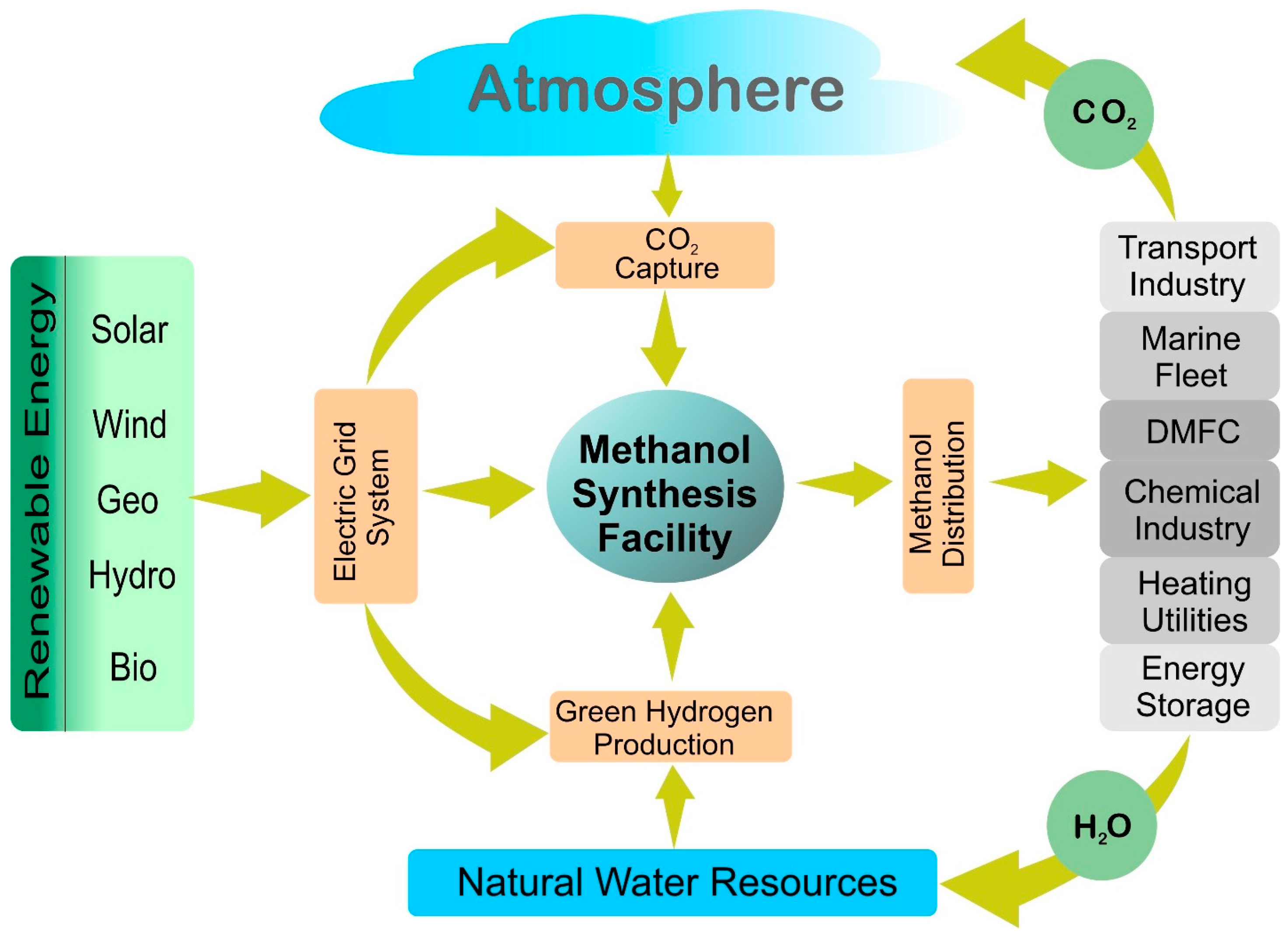
DMFC is incorporated with a proton exchange membrane for internal transfer of proton (H+) from anode to cathode, while electrons (e−) are transferred via external circuit producing electricity. Toshiba, a Japan-based company, in 2009 launched a portable modular fuel cell powered with concentrated methanol which was used as external power source for mobile devices [73]. The release of CO2 after methanol production as fuel has no adverse effect on the environment, as the CO2 is recaptured from the atmosphere for methanol synthesis. Summarizing from previous works, a schematic diagram of clean methanol synthesis from renewable energy and its utilization with net zero emissions is depicted in Figure 1.
3. Key Ingredients for Clean Methanol
Conventionally, methanol is produced from syngas (a mixture of CO2, CO and H2), which is primarily obtained from the reforming of fossil-fuel-based natural gas, coal or oil, while a major portion is obtained from natural gas. Methanol was first commercially produced from syngas in 1920s by Badische Anilin und Soda Fabrik (BASF) using very challenging conditions of 350–400 °C temperature and 240–300 bar pressure to compensate for the low activity of the catalyst used [74,75]. The major problem of using low temperature/pressure catalyst was in the impurities, such as sulfur from fossil fuel along with syngas, poisoning the catalysts. With the development of purification technologies, Imperial Chemical Industries (ICI) group successfully produced sulfur-free syngas. Subsequently, the researchers from this group produced methanol with Cu-based catalyst in much more favorable operating conditions of temperature and pressure of 200–300 °C and 30–54 bar, respectively [40].
The methanol synthesis using syngas route has a significant impact on the environment due to the direct usage of fossil fuels. In addition to the GHGs from the methanol consumption, a large amount of CO2 is also generated from the production plant itself. For instance, before feeding the syngas from the reformer section to the methanol production section, its CO2 content is required to be controlled by extracting the excess quantity of CO2. Without proper handling of the extracted CO2, this would result in an addition to net GHGs emissions [76].
With preference to utilize a greener approach, methanol should therefore be produced from clean and renewable raw materials while all energy utilities are obtained from clean resources. In other words, as an alternative to coal or natural gas, atmospheric CO2 and green H2 from water electrolysis are the integral components for production of clean methanol. In this scenario, catalytic hydrogenation of captured CO2 over Cu/ZnO-based catalyst can be a viable option to produce clean methanol. For instance, Bellotti et al. studied the feasibility of a wide range of methanol production capacities (4000–50,000 ton/year) with captured CO2 and H2 from water electrolyzer using overproduced grid electricity. They found large capacity plant (50,000 ton/year) more economical option by considering the influence of capital investment and product selling cost [77].
During the transition from fossil to renewable and clean resources, power-to-x terminology is used (x can be any form of energy), whereby in this study “x” is the category of liquid fuels, specifically methanol [78]. In any power-to-methanol process, by and large, initially H2 is produced from clean power-to-hydrogen process which can be powered by solar, wind, geothermal or hydrothermal energy [79]. Industrially, the green H2 is the most valuable and expensive component of clean methanol production plant [80].
The second component to produce clean methanol is CO2 where it is captured from atmosphere and industrial off-gases. The sources of atmospheric CO2 are mainly from industrial processes such as cement, fertilizers and steel manufacturing; it can be captured innovatively and subsequently directed to the methanol production plants. In some methanol utilization processes such as DMFC and methanol-water electrolysis or direct combustion, a significant amount of CO2 is released, which can also be recycled in order to close the carbon looping. Other renewable sources of CO2 and H2 may include biomass, natural organic feed stock and effluents from organic food processing industries; for example: vegetable oil when subjected to a gasification process [81,82,83].
In a nutshell, for sustainable production of clean methanol, there is a strong need of a sustainable supply of H2 for the decarbonization of the environment [84,85,86]. Following this strategy, several commercial facilities for producing clean methanol have emerged; for example, Liquid Wind, a Swedish company has committed to develop 10 methanol production facilities by 2030, each with a capacity of about 50,000 tons of e-methanol/year [87,88].
3.1. Production of Green Hydrogen
About 95% of global hydrogen (H2) is produced from fossil fuel sources, such as natural gas, coal and oil. The production of H2 has been classified into grey, blue and green H2, based on source and production strategy, as shown in Table 2. Grey H2 is produced by steam reforming of fossil fuel and termed as “grey” due to substantial GHGs emissions during the process [89]. The source of blue H2 is also fossil fuel, but the production process must be equipped with efficient CO2 capturing facility (100%) and have minimal GHGs impact on environment [90]. Green H2 is a totally environmentally-friendly process with zero GHGs emissions [91,92], produced by water electrolysis. The electrolyzer must be powered with renewable energy sources to avoid any GHG emission into the atmosphere during its entire production process [93]. This green H2 is the key approach towards achieving zero emission target of 2050 set by global climate communities. However, despite of the zero emissions from electrolysis operation, an electrolyzer manufacturing process could inevitably lead to GHG emissions, particularly if critical way materials are used, which should be taken into account for net zero emission target [94].
Future world energy will be based on two major sources: electricity and H2, due to the availability of water [93]. Electricity is directly utilized by end user, however, H2 has the challenging issues of storage and transportation, which can be solved by its conversion into methanol, as discussed by Papadias et al. [95]. Currently, green H2 production processes are expensive due to slow processing and large capital investment. Consequently, research efforts have been focused on reducing H2 production cost by developing more efficient catalysts and improving other auxiliary processes. The US Department of Energy has emphasized the reliability on renewable energy and has set a target of a stabilized price of green H2 to be $1/kg by 2030, with an interim value of $2/kg of H2 by 2025 [96].
A typical electrochemical reaction scheme for water splitting in an electrolyzer at respective electrodes is as follows [97]:
Cathode reaction:
2H2O + 2e− → 2H2 + 2OH−
Anode reaction:
2OH− → 1/2O2 + H2O + 2e−
Overall redox reaction:
2H2O → H2 + 1/2O2
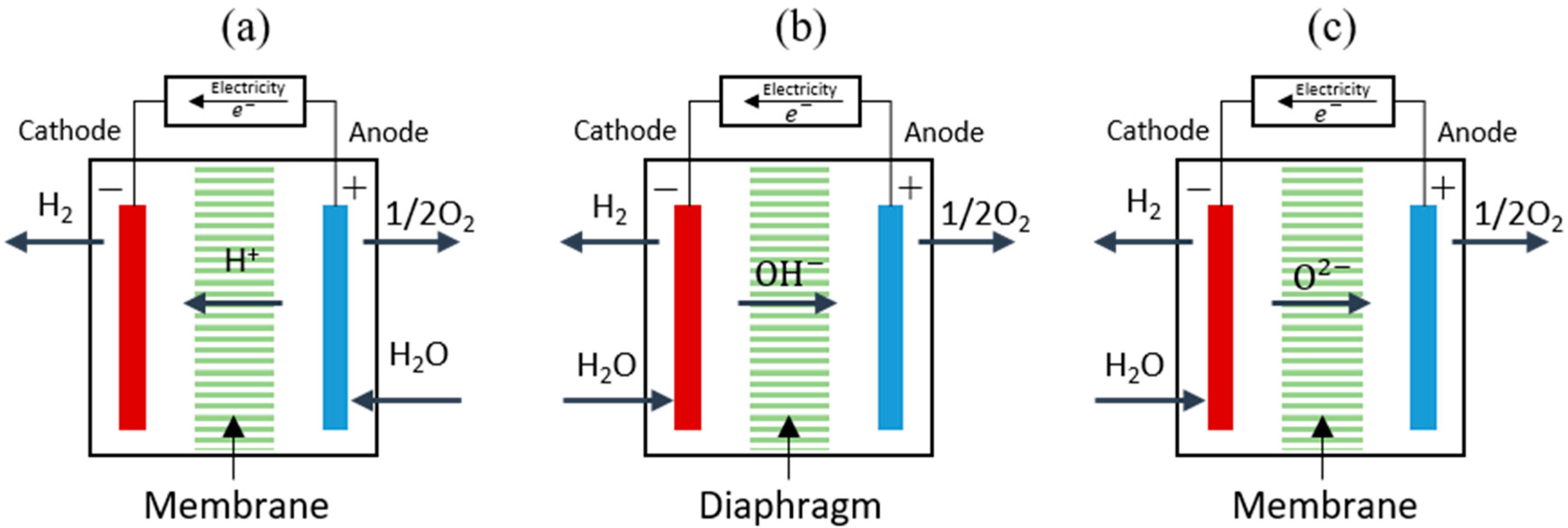
From the above-mentioned reactions, water splits into H2 and oxygen (O2) in a ratio of two-to-one by consuming the electrical energy. There are three major technologies for producing H2 from water splitting: (1) proton exchange membrane electrolysis (PEMEL), (2) alkaline water electrolysis (AEL), and (3) high-temperature solid oxide water electrolysis (SOEL). Schematic representation and reaction scheme of all three types of electrolysis processes can be seen in Figure 2 [98].
The PEMEL and AEL are low temperature electrolysis strategies to split water in acidic and alkaline media, respectively. In PEMEL, water is fed at the anode and oxidized to O2 at an iridium-based catalyst along with the release of protons and electrons, an oxygen evolution reaction (OER). The electrolysis cell contains a polymer electrolyte membrane (Nafion) having sulfonate functional groups to transport protons from anode to cathode. At cathode, a Pt-based catalyst assists protons to combine with electrons from an external field to generate H2 gas, a hydrogen evolution reaction (HER) [99]. PEMEL is operated at low temperature of between 20–80 °C and can generate ultrapure H2 and O2 from water splitting [98]. In spite of the ease of low temperate operation and product purity, the requirement of a noble metal catalyst raises the production cost. A noble metal catalyst is also necessary to withstand the corrosive acidic environment. To tackle this issue, Tajuddin et al. has recently developed non-noble based corrosion resistant electrodes for PEMEL applications. These electrodes can withstand the acidic environment of PEM electrolysis without any notable degradations [100]. Their study provides novel opportunities and new perspectives of replacing costly noble metals, particularly iridium, and can significantly reduce the production cost of H2.
In AEL, the electrolyte solution is composed of 20 to 30% aqueous alkaline solution and the cell is operated at low temperatures of 30 to 80 °C [98]. The feed water is fed to the cathode where it is oxidized to H2 and generates OH− ions. These hydroxyl ions pass through the alkaline media towards the anode to release electrons and produce oxygen. In an alkaline water electrolysis process, the problem of corrosive acidic media can be solved by providing alkaline water which can accept a broader range of non-noble metal-based electrocatalysts [97]. The problem associated with this AEL system is the sluggish reaction kinetics, and hence, a very high processing time which complicates its applicability on a large scale [101].
Solid oxide electrolysis (SOEL) is performed in a solid oxide electrolysis cell (SOEC) which works on the reverse principle of a solid oxide fuel cell, used for electricity production from pure H2 and O2 [102]. In SOEC, steam is fed at cathode and it undergoes reduction at high temperatures of 600–1000 °C to produce H2 and oxide ions [103]. Due to the high temperature, oxide ions can travel from cathode to anode via some oxide-conducting electrolyte medium, where it captures an electron from an outer circuit and generates oxygen gas. This process of H2 production has a good efficiency of more than 80% [102], however, it has the drawback of high-temperature operation [104]. To overcome this issue, researchers have made efforts to develop electrolytes for SOEC which can transfer ions at comparatively at low temperatures. Ishihara et al. performed steam electrolysis at 600 °C in SOEC having LaGaO3-based electrolytes and successfully achieved H2 production rate of 70 L/min at 1.8 V of applied potentia [105]. Further research on low temperature electrolytes and innovative cell materials for SOEC can be found in a review article by Singh et al. [106] and Nechache et al. [107]. Due to its high conversion efficiency, SOEC has successfully attained commercial operation. A German company (Sunfire GmbH, Dresden, Germany) working on renewable and clean energy successfully tested world’s largest SOEC module producing 63 Nm2/h of H2 from water steam and renewable electricity [108].
Several renewable energy sources including solar, wind and biomass have great potential to produce green H2. The production of green H2 is not only limited to water electrolysis; there are several other process available such as solar to H2, wind to H2 and biomass to H2 as described in the following subsections.
3.1.1. Solar to Hydrogen
Hydrogen (H2) production in water electrolyzer using solar electricity is a two-step process. Firstly, sunlight is converted to electricity using a photovoltaic (PV) cell which is then used in electrolyzer (EL) for water splitting. Alternatively, H2 can be produced from sunlight using photocatalysis (PC) and photo-electrocatalysis (PEC) [109] which is a direct water-splitting route from solar to H2 and thus avoids the energy losses by combining the two steps into a single one. Sunlight is directed onto the electrolysis solution containing photocatalyst or photo-electrocatalyst, which enables the water splitting reaction and thus produces H2 and oxygen (O2) without additional electricity [110,111].
In the PC method, the metal oxide-based semiconductors (photocatalyst) particles are dispersed in the aqueous electrolyte solution to generate electrons -holes pairs under sunlight irradiation. These pairs migrate towards the active sites of respective electrodes to produce H2 and O2 [112,113,114]. In spite of direct exposure to sunlight in PC technology, the drawbacks include slow kinetics, unfavorable thermodynamics and some safety issues [115]. For instance, the separation of H2/O2 from the PC cell is needed to avoid H2 explosion in contrast with photovoltaic-electrocatalysis (PV-EC) and PEC [116]. Subsequently, research efforts have been focused to overcome these issues for better efficiency of converting solar energy to H2 by improving the semiconductor materials. For example, Wang et al. have developed Pt co-catalyzed BaTaO2N photocatalyst that produced 100 times more efficient H2 production compared to previous studies [117].
To overcome the problem of H2/O2 separation in PC method, the PEC system contains photocatalyst on electrodes, provided that large surface area electrodes for high exposure to sunlight is required [118]. The main issue with this system is the large surface area, which can be clarified by designing more efficient photoelectrodes. In this context, Mehtab et al. reported metal-free highly porous N-rich g-C3N4 semiconductor material for PC and PEC systems which worked under broader spectrum of sunlight and showed higher efficiencies of 12% [119]. At present, this technology developed in Spain is in progress to produce 100 kg/day of H2 and about 10 tons of gas/day for commercialization [120].
Historically, when producing H2 from sunlight, the overall solar to hydrogen (STH) efficiency is an important parameter to consider, as shown in Table 3. Gibson et al. developed a model for predicting STH efficiencies of PV-electrolysis system under the influence of different operating parameters to provide 12.4% STH efficiency using a PV-PEM system [121]. Jia et al. have achieved 30% STH efficiency using PV-PEM system with specially designed triple junction solar cell [122]. Similarly, Khan et al. have achieved 28% STH using concentrated solar light and a relatively inexpensive alkaline water electrolyzer [123] with the highest efficiency. Yi et al. have successfully achieved cost-effective H2 production using ultrathin cobalt/iron-molybdenum oxide with STH efficiency of 15.1% in an alkaline water electrolysis system [124]. Pan et al. designed a cost-effective PV electrochemical water splitting by combining Ni/Co/Fe-based-OH nano-sheet electrocatalysts with specially designed monolithic perovskite/silicon tandem solar cell, and achieved over 20% STH efficiency [125]. Si et al. used natural solar irradiation over commercially available PV cell and controllably prepared Co-Fe-Ni-based electrodes grown on metal foam, providing 12.7% STH efficiency in PV-EL system for cheaper and commercially viable products [126].
Other alternative technologies developed for solar driven water splitting are solar-thermochemical (STC) water splitting and bio-photolysis (BP) H2 production. In STC, concentrated solar light is directed onto a water source containing certain thermally active chemical materials. A water-splitting reaction is initiated by thermal energy acquired from sunlight, which passes through series of redox reactions in a cycle to produce H2 and O2 [127,128]. Water splitting in STC undergoes either a two-step redox reaction at temperature range of 1300–1800 °C or a multi-step looping at temperatures less than 1000 °C [129]. In two step STC, firstly, metal oxides (MxOy) are reduced at high temperature under concentrated solar irradiation and produce O2, followed by oxidation at relatively lower temperature producing H2, where it completes the cycle [130]. On the other hand, in a multistep STC system, the reaction cycle passes through several intermediate steps between final H2 and O2 producing reaction at temperatures less than 1000 °C [131]. Taking advantage of a multi-step STC system, several thermochemical cycles with a broader range of materials have been investigated and have potential for future H2 production [131,132]. For example, Sadeghi et al. devised a Cu-Cl molten salt-based thermochemical cycle for H2 production and estimated the minimum product cost of 7.58 $/kg of H2 with overall thermal efficiency of 29.18% [133]. STC has achieved better solar to hydrogen efficiencies due to higher temperatures, however suitable reactor designs and optimal water splitting materials must be developed in order to be commercially viable [134,135].
During H2 production in BP system, water-immersed sunlight-activated micro-algae is responsible for the conversion of solar light to H2 via water splitting [133,136]. This route of green H2 production has significant potential for future industries due to its relatively easy operation, compact design and cost-effectiveness [137]. Currently, active research studies have been conducted worldwide to optimize the operating conditions of pH, temperature, light intensity and oxygen level before any large scale implementation [138,139]. In view of this, water splitting under direct or indirect sunlight might have sufficient scope to produce green H2 which can be fed to green methanol production to effectively replace the consumption of fossil fuels [42].
3.1.2. Wind to Hydrogen
Solar-driven hydrogen (H2) production is a growing technology for utilizing natural resources but lacks a consistent energy supply. To overcome this problem, wind energy is an alternative renewable source which can be integrated with the existing photovoltaic-electrolysis (PV-EL) system. Electricity produced from wind energy can be coupled with water electrolysis and hence can play its vital role in decarbonizing and making a future free of carbon [140,141]. For example, Europe’s first Hydrogen Valley, in Northern Netherlands, could generate a revenue of €126,000 annually from each wind turbine by converting wind energy into H2 [142].
Owing to the huge electricity generation capability of wind farms, researchers are exploring the possibility of alternative H2 storage. For instance, Dinh et al. developed a model to assess the viability of H2 production using electricity from wind farm and found a balance H2 price of about 3.22 $/kg of H2 [143]. Subsequently, Douak et al. performed the on-spot H2 production from wind farm and estimated the cost of product as low as 1.214 $/kg of H2 [144]. Ziazi et al. presented a techno-economic analysis of H2 production in alkaline water electrolysis powered with wind electricity using different types of wind turbines. It was shown by the authors that General Electric 1.5 MW wind turbine (General Electric Company, Boston, MA, USA; Model: GE 1.5sle) has highest efficiency but with the drawback of a high investment cost [145]. Hence, it was shown that wind-to-H2 is a feasible and clean H2 production strategy using suitable electrolyzer scheme with zero hazardous emissions to the atmosphere.
Despite the fact that clean H2 might be produced from offshore wind farms, there is still an issue of storing the H2 at offshore sites [146]. Heuser et al. analyzed the electricity production from wind energy in Patagonia followed by its liquefied shipment to Japan. The estimated H2 price at output of electrolyzer was 2.16 €/kg, which increased to 4.44 €/kg upon its arrival to Japan [147]. This increase in cost could be due to handling and transportation of liquefied H2, which makes the overall process more expensive [50]. Alternatively, it could be converted to liquid fuels such as methanol, which is easy to store as well as transport [148]. Bazaluk et al. conducted a study on the potential to produce around 6.83 to 32.43 million tons/year of green methanol from renewable sources such as recycled waste and wind power [149]. Their study has shown the promising strategy of exploiting these renewable sources to obtain valuable green methanol sustainably.
3.1.3. Biomass to Hydrogen
Lignocellulose is the most abundant biomass on earth with annual production of 181.5 billion tons, as reported by Dahmen et al. in 2019 [150]. Currently, the waste biomass comes from different sources such as residue of food crops, forest plants, marine life and waste generated by bio-products manufacturing industries. Historically, solid biomass was subjected to combustion for generating energy; however, new routes have been discovered in using solid biomass to obtain useful products [151,152]. H2 is one of the valuable products which can be extracted from this biomass by many established thermochemical, biological and electrochemical processes [153].
In thermochemical treatment of biomass, it is passed through a gasification process to convert it into gaseous form with different compositions of CO2, CO, CH4, H2 and other hydrocarbons, depending upon the nature of the fed biomass [154]. The gasification process can be performed in numerous ways such as dry and steam gasification, partial oxidation, pyrolysis and combination of these processes [155]. A gasification route is selected based upon the C/H ratio required in gas production and post-processing. If the subject matter is H2 production, the produced biogas is subjected to steam reforming to produce H2 rich syngas followed by carbon capture to produce H2 [153,156]. In the case of methanol production, the produced syngas is directly fed to a methanol production plant after a necessary adjustment in its composition [157].
Gasification is performed at high temperatures of around 800–1000 °C due to many endothermic reactions and hence it is an energy-intensive process. In contrast, biological processes are operated at very low temperatures of around 30–60 °C and thus are less energy-intensive [153]. Moreover, the microorganisms required to carry out the gasification process can be easily produced via replication process [158]. Dark and photo fermentations are two important biological processes responsible for degradation of subjected biomass into useful gases. Dark fermentation is a light-independent pathway carried out by anaerobes and green carbohydrate-rich microalgae to produce bio-hydrogen [159,160]. Pasaribu et al. processed palm oil mill effluents (POME) via dark fermentation for bio-hydrogen production by suppressing the functioning of methanogenic bacteria [161]. They reported the highest bio-hydrogen production rate as 2824.2 mg of H2/L of POME at optimal conditions. Alternatively, photo-fermentation relies on sunlight as a source of energy for photosynthesis. Instead of using sugars during dark fermentation, this pathway absorbs sunlight as a source of energy which is more advantageous [139]. Zhang et al. compared the performance of both dark and photo-fermentation in terms of bio-hydrogen production. The authors found photo-fermentation more effective as it provided a high H2 content [162]. Overall, fermentation process is low energy consuming, however, it gives very low bio-hydrogen production rates and conversion efficiencies [163].
Other cutting-edge technologies for producing bio-hydrogen may include microbial electrolysis cell (MEC) and aqueous phase reforming (APR) of biomass. In MEC the effects of both microbial action and electrolysis are combined to boost biomass decomposition process [159]. Electrochemically active microorganisms generate CO2, electrons (e−) and protons (H+) at anode by oxidizing organic matter. These e− travel to cathode under the influence of external circuit, while H+ migrate to cathode through electrolyte solution. At cathode, electrically driven e− combine with H+ from solution to produce bio-hydrogen [164]. In APR of biomass, the oxygenated hydrocarbons are processed over a suitable catalyst, such as platinum-based catalysts, for producing an H2 rich gaseous stream [64]. This technology can take advantage of utilizing the leftover carbon content of biomass-processing industries such as effluents of Fischer-Tropsch (FT) synthesis plant [65]. Given these findings, instead of direct burning, a more efficient fuel of bio-hydrogen can be produced from biomass using several different technologies. In this way it can be a helping hand in decarbonizing the earth’s climate for clean energy production in the future. Nevertheless, improving the production rate and efficiencies for H2 production from biomass processing remain as ongoing research efforts.
In view of the available processes for production of green H2 from renewable sources, a comparison of advantages and associated challenges for different technologies has been summarized in Table 4.
3.2. Recycled Carbon Dioxide
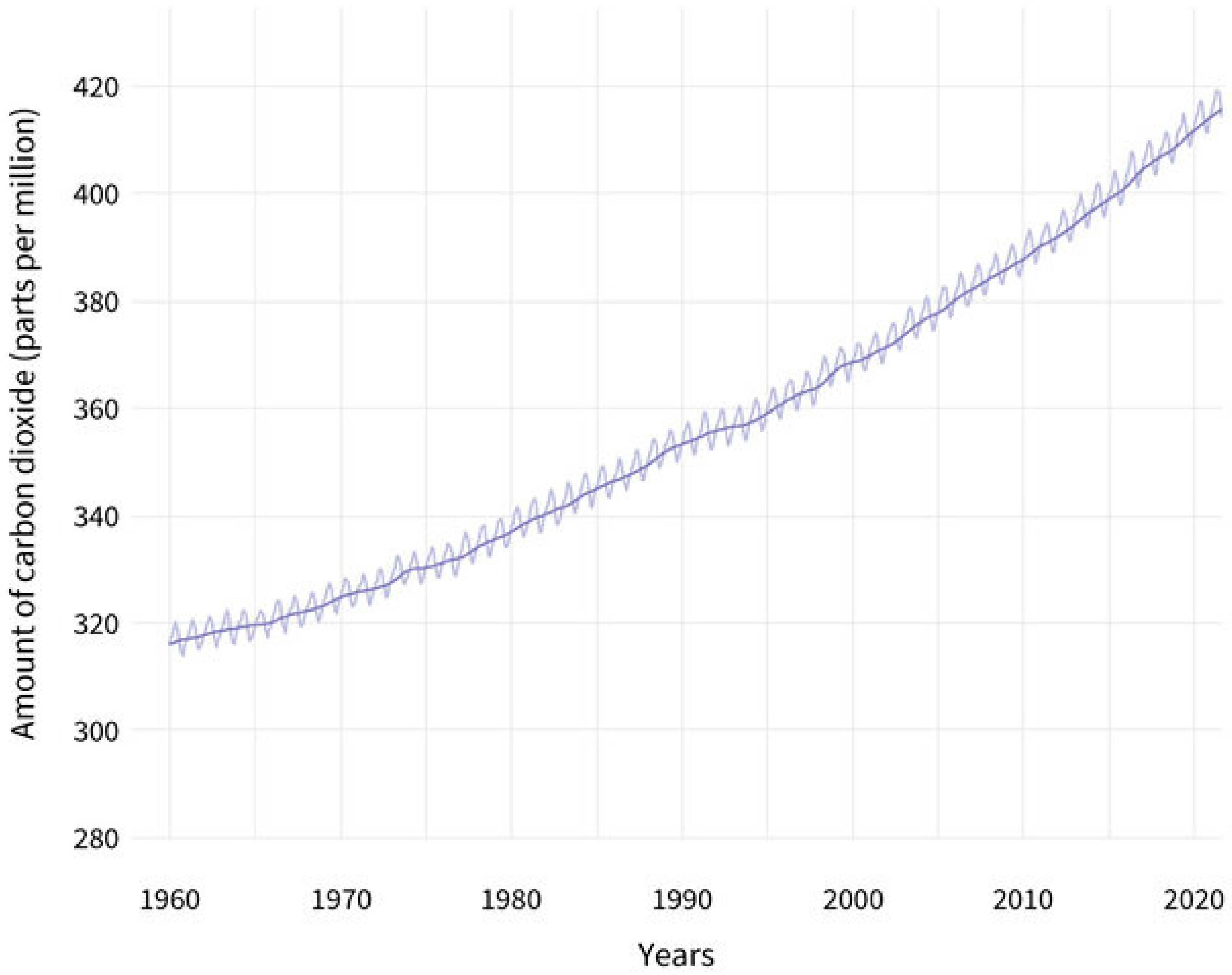
The recycled CO2 from direct air capture (DAC) or industrial emission can complete the carbon cycle through methanol production. Based on an analysis report from NOAA’s Global Monitoring Laboratory, the global average atmospheric CO2 reached 414.72 ppm in 2021. It has reached a new high-level record amount of CO2 in spite of decelerated human activities due to COVID-19 pandemic, as shown in Figure 3 [165]. Presently, the average value of CO2 is 417.2 ppm which is more than 50 percent above pre-industrial levels [166]. The increasing concentration of CO2 depicts that its natural sinks (that removes CO2 from atmosphere), which are plants and oceans, are not taking out an equivalent amount as that being emitted. This imposes the need of the installation of other CO2 capturing points and at the same time reducing the further emissions to balance the atmospheric concentration. Methanol production from captured CO2 will reduce further emissions in the atmosphere [17,167].
Even though many fossil-fuel-based industries are trying to switch to renewable sources, some industrial plants, such as cement, iron, steel and chemical manufacturing, are responsible for considerable amount, about 22% of CO2 emissions [168]. The record of CO2 emissions over the year showed that its rate is reasonably high during the winter seasons, which shows high consumption of fossil fuels by heat-producing facilities. Moreover, the analysis of CO2 emissions showed high emissions coming from industrial sites, especially in developing countries [169,170]. CCU units can harness the CO2 emissions to atmosphere to prevent it from reaching an adverse level of 8 Gt of CO2 in 2050 [171].
3.2.1. CO2 from Direct Air Captured
CO2 from the atmosphere is directly captured from air using well-developed DAC technology. Currently, there are 19 DAC plants operational worldwide, capturing around 0.01 Mt CO2/year [172]. In comparison with the available CO2 in atmosphere and net zero target of 2050, this installed capacity is too low and needs to increase up to 60 Mt CO2/year by the end of 2030. To meet this target, several large capacity DAC plants are under development and will be operational in the near future, including a 1.0 Mt capacity plant in US which will be operational in mid 2020s [173].
Technologies used in DAC are based on suitable solid (s-DAC) or liquid (l-DAC) sorbent to selectively extract CO2 from the ambient air [174]. Ambient air is brought in contact with these sorbents at certain temperature and pressure, depending upon the physiochemical nature of the sorbent. CO2 is attracted towards the sorbent while leaving behind the rest of the gases. The CO2 rich sorbent is then processed under reverse operating conditions to desorb the attached CO2 and regenerated for the next cycle. The sorption of CO2 on the sorbent can be either chemical (chemisorption) or physical (physiosorption). In chemisorption, CO2 is attached to the sorbent via chemical bonds which require a considerably high level of energy for their regeneration [175]. For instance, in case of alkaline or amine solution as sorbent, it is converted to carbonates and carbamates by capturing CO2 and then subjected to high temperature to break the established bonds [176,177]. Conversely, the process of physiosorption involves relatively weaker Van-der-Waals forces which are easy to regenerate, however, it has the drawbacks of lower capacity and slow processing rates [178].
The regeneration of liquid sorbents such as aqueous alkaline solutions requires a high temperature of above 800 °C, whereby the overall process is energy intensive [179]. However, solid adsorbents can be easily regenerated at low temperatures of around 80–120 °C and hence have potential application in future DAC processes [180,181]. Shi et al. summarized a number of solid and liquid sorbents for capturing CO2 [178]. Researchers have focused on less energy-intensive, reduced-cost, sustainable materials and on improving contactor designs for better efficiency [182]. Numerous synthetic metal oxide sorbents, comprised mainly of Ca, Mg, Li, Na, K, Sr and Ba metals, have been developed with the more commonly-used CaO and MgO [183]. In addition to the metal oxide sorbents, zeolite-based sorbents either in pure or modified forms are also used for capturing CO2. For example, owing to the small pore size of zeolite A (0.4 nm), it can be used for capturing CO2 (kinetic diameter 0.36 nm) from post-combustion gases [184]. In modified forms, amine functional groups can be introduced to zeolite framework, which enhances its adsorption capacity for CO2 capture [185]. Consequently, several alkanolamine-based liquid sorbents that were studied by Barzagli et al. possessed equal efficiency, along with lower regeneration energy, as compared to aqueous alkali hydroxides [186]. Although s-DAC and l-DAC are developing continuously, their use is associated with limited number of regeneration cycles, which generates waste upon their disposal [183].
With regards to waste generation, membrane based direct air capturing (m-DAC) is the preferred method, compared to s-DAC and l-DAC due to its less energy-intensive and more cost-effective nature [187]. In m-DAC, a CO2 selective membrane is used to capture CO2 from ambient air, however, a large membrane surface area is required due to the small concentration of CO2 [188].
In summary, the capturing of CO2 from the air is more energy intensive and expensive than capturing from a point source of emission. This is because CO2 present in atmosphere is much more diluted than flue gases of a power station or cement plant [168]. This contributes to higher energy demand and results in high cost of DAC in comparison to other CO2 capture schemes.
3.2.2. CO2 Captured from Industrial Emissions
It is important to control CO2 emissions into the atmosphere to manage the increasing temperature and rapidly changing climate. Although DAC is a negative emissions strategy, it has the benefit of capturing distributed and small point emissions, for example, transportation, which accounts for 12 to 18 Gt CO2/yr [178]. Larkin et al. have presented ways to capture CO2 from transport emissions, but it is difficult to direct it into further utilization processes [189]. On the contrary, the large point source capture is more important for downstream processing of captured CO2 into useful synthetic fuel such as methanol.
Fossil fuel-based industrial sectors such as H2 production, chemical production, natural gas processing, fertilizer manufacturing, power generation, cement manufacturing, steel and iron processing are major CO2 emitters [168]. The energy sector, namely heat power and transportation, accounts for around 73% of total emissions; while other process industries, namely cement, iron and steel, contribute about 18%, and residential and agricultural activities are about 9% [190,191]. Due to high temperature (>1000 °C), processes of cement, iron and steel manufacturing industries, it requires massive energy inputs which can be fulfilled mainly by coal utilization [192,193]. Instead of minor contribution of CO2 from process industries, the concentration of CO2 in their flue gas is rather high () as compared to power and heat flue gases (), making it more suitable target for CCU [190].
Currently, there are three main approaches available to capture CO2 from large-scale fossil fueled industrial sectors: (1) post-combustion capture; (2) pre-combustion capture; and (3) oxy-fuel combustion capture. Among all three technologies, post-combustion carbon capture is the oldest one, due to its ease of operation and installation without any significant changes in existing plant [168]. This technology is based on removal of CO2 from combustion flue gases, mainly consisting of CO2, O2, N2, H2O, SOx and NOx, depending upon the nature of the fuel burned. Around 10–15% of the total volume of flue gases subjected to post-combustion treatment is CO2 [194]. The second technology, pre-combustion carbon capture, refers to the removal of CO2 from fossil fuels before feeding to combustion process [195]. In this technology, fossil fuel is first passed through a gasification process to convert it into syngas (CO, H2 and CO2) which is then subjected to water gas shift reaction to convert CO to CO2 and H2. The final mixture of CO2 and H2 having 15 to 50% CO2, is then fed to a CO2 removal process and clean H2 is used for combustion purpose, while rejecting clean flue gases [196]. Pre-combustion capture technology utilizes a highly concentrated stream of CO2 for carbon capture and hence can perform more efficient removal. The third technology, namely oxy-fuel combustion is one of the leading technologies for carbon capture and utilizes pure oxygen instead of air for fossil fuel burning [197]. An air separation unit separates oxygen from air while leaving behind the major portion of N2. Flue gases produced from this oxy-fuel combustion are more concentrated in CO2, which is then removed from it in a flue gas processing unit [198].
Several process schemes have been established to extract the considerable amount of CO2 from these flue gases, such as absorber/stripper arrangement, pressure/temperature swing adsorption and membrane separation [175,199,200]. In absorber/stripper process scheme, a CO2 absorbing solution is brought into contact with flue gas to absorb CO2 from it at a low temperature (40–50 °C). This CO2 rich solution is then sent to the stripper where it rejects the absorbed CO2 at reverse conditions of high temperature (90–130 °C) [175,201]. This scheme is well established but is less favorable due to liquid waste generation, owing to the limited number of cycles of solvent regeneration. To overcome the problem of waste generation, adsorption on solid surface is used via pressure/temperature swing adsorption (PSA and TSA) operation [199].
PSA is a cyclic operation which removes CO2 from flue gas by periodically adsorbing and desorbing at high- and low-pressure conditions, respectively. While, in TSA, the same procedure is followed, but with temperature instead of pressure, explicitly, adsorption at low temperature and desorption at high temperature [202,203]. Membrane-based CO2 capturing is a very promising industrial option, especially when dealing with high concentrations of CO2, such as in the case of pre-combustion CO2 capture [200]. Membrane-based CO2 capturing is preferred over other competitive technologies due to its small footprint, lower energy consumption, increased economy and increased ease of operation [194,204]. Recently, Chen et al. reviewed the developments in membrane material for capturing CO2 from all three strategies, pre-combustion, post-combustion and oxy-fuel combustion, showing the great potential of this technology in future [205]. Initially, the installation of carbon capture was an energy-expensive and profitless step and therefore it was difficult to be opted by small industries. But technological developments and availability of smart processes for effective utilization of CO2 are making it a profitable and viable option for more companies.
3.2.3. CO2 Produced from Biomass
Biomass which in the form of dry or wet, is a source of energy readily available, however, it could be responsible for CO2 emissions with improper handling [206]. Dry biomass can directly be subjected to combustion for generating energy at the expense of environmental impact. One solution is to use the same biomass subjected to thermochemical treatment to form combustible gases for environmentally-friendly fuels production as discussed in Section 3.1.3.
The gasification of biomass is mainly performed to convert it into clean H2 fuel along with a side product, CO2, which is generated in very abundant amount during this process due to the organic nature of subjected biomass. In this scenario, CO2 is captured from biogas in order to produce value-added H2 fuel [207,208]. Biomass usage is not only limited to H2 production but also used for producing syngas, bio-methane and other light hydrocarbons fuels [209]. In any gasification process, excess CO2 must be removed via either in situ or post process techniques, as it imparts negative value to any produced fuel. Dinca et al. produced syngas by biomass gasification while capturing the CO2 by using liquid absorption method [210]. Dashtestani et al. used novel Ca/Fe based sorbents for efficient removal of CO2 via calcination-carbonation looping from biomass gasification [211]. They also studied the effectiveness of sorbent material over number of regeneration cycles, which is very important stability criteria for a newly developed sorbent.
Bio-methane is another valuable product of biomass which can act as a potential substitute for many natural gas-based processes [209]. The production of bio-methane can be done via either anaerobic digestions (AD) of organic matter or biomass gasification followed by methanation. AD is a biological process performed in bio-digester producing CH4 and plenty of CO2, 65 and 35%, respectively [212]. While in case of gasification for biomethane conversion, the firsthand gasification product, namely, syngas, is fed to methanation reactor which converts it into CH4 and CO2. This raw mixture of gases must be subjected to CO2 separation processes to produce high purity bio-methane.
CO2 captured from these biomass processing plants can be utilized for synthetic fuel production, namely methanol, by reacting with on-spot green H2. Menin et al. performed techno-economic assessment of methanol production from captured CO2 along with bio-methane production from biomass gasification [213]. The supply of green H2 was a major concern in earlier evaluations of on-site methanol production, but one which can be overwhelmed by recent technological advancements in renewable H2 production schemes [214].
It is important to note here that CO2 from biomass is, indeed, “biogenic”, therefore it should not be counted as an emission source. This leads one to consider biomass as neutral with respect to greenhouse gas emissions due its rapid regrowth. Hence, capturing of CO2 from biomass is actually a negative emission strategy to mitigate the climate change [215].
4. Production of Clean Methanol
After discussing the key raw materials for clean methanol production, namely green H2 from renewable energy sources and recycled CO2, this section will discuss an important method for the production of e-methanol by utilizing these sources, namely heterogeneous catalysis. E-methanol is produced by reacting green H2 with captured CO2 from industrial sources or ambient air [42]. Because of the green H2 from renewable energy and captured CO2, e-methanol is an alternative and net-carbon-neutral fuel. There are several processing routes for producing methanol from captured CO2, including a well mature catalytic hydrogenation of CO2 with green H2, which is responsible for e-methanol production [217]. In catalytic hydrogenation of CO2, both gases are processed over Cu/Zn based bimetallic or other multi-component catalysts at certain operating conditions. The operating conditions vary depending upon the nature and composition of catalyst employed. The normal operating conditions were in the range of 200–250 °C temperature and 3–10 MPa of pressure. The following reaction scheme is followed during catalytic hydrogenation of CO2 [218],
CO2 + 3H2 → CH3OH + H2O ∆H298K = −49.5 kJ/mol
CO2 + H2 → CO + H2O ∆H298K = +41.2 kJ/mol
CO + H2 → CH3OH ∆H298K = −90.6 kJ/mol
As shown from the above reaction scheme, the nature of this reaction is overall exothermic, which is more favorable at low temperatures. At low temperatures, it is difficult to energize the stable CO2 molecule, which decreases the reaction speed, while at high temperatures it is difficult to achieve good conversion. Therefore, well-optimized operating conditions are required for good conversion and high process yields. Other than operating conditions, several other parameters such as catalyst development and reactor designs also play a role for high process throughput [218,219]. Initially, the same commercially available Cu/ZnO/Al2O3 (CZA) catalyst, specialized for syngas to methanol conversion was deployed to CO2 hydrogenation. Due to poor selectivity of CZA for methanol from CO2, several other catalytic approaches were developed incorporating other metal oxides on a Cu/ZnO base, including ZrO2 as one of the best additions [218,220,221]. Recently, Zhang et al. performed a detailed analysis of catalytic conversion of CO2 into e-methanol and addressed other challenges associated with this route [219].
Despite catalytic development for enhanced CO2 conversion and process efficiency, another big challenge is the downstream removal of an essential by-product, water. Water separation is the last step of any methanol production facility to get high purity product, which is mainly achieved by distillation technique. Numerous research studies have been conducted in the distillation for efficient removal of methanol-water mixture by consuming less energy [222,223].
5. Post-Synthesis Methanol/Water Separation
In any methanol production route, water is a compulsory by-product which needs to be separated to purify the final product. Due to polar nature of both components, water-methanol makes a miscible mixture because of hydrogen-bonding. The convenient and conventionally adopted method for removal of water from this organic-aqueous mixture is by distillation [224]. The remarkable difference in boiling points of both species, which is 100 °C for water (heavier component) and 64.7 °C for methanol (lighter component), indicates the feasibility of separation by distillation. Distillation is well established and adapted thermal separation technique, however, it has the drawback of high energy consumption [225].
5.1. Challenges and Improvement in Methanol/Water Separation
In distillation operation, re-boiler and condenser are major energy consumers, and it accounts for approximately 40% of total energy requirement of a chemical industry [225,226]. To have better process efficiency and energy economy, several improvements were made in existing distillation process including heat integrated distillation, multi-effect distillation and heat pump assisted distillation [227,228,229,230,231]. Liang et al. worked on making distillation process energy efficient by combining preconcentration and entrainer recovery columns instead of 3-column configuration of conventional extractive distillation which is good energy and capital cost saving [232]. Liu et al., proposed a four-column combination strategy for methanol-water distillation having integrated condensers scheme to decrease the energy duty of both re-boilers and condensers [225]. They simulated their process scheme while saving, overall, 34.5% and 41.8% cooling and heating loads in condensers and reboilers, respectively. Even though there are numerous extractive distillation process advances, the consumption of plant energy is still high, thus alternative techniques for better separating efficiency are preferable.
Hybrid systems incorporating a combination of different distillation-membrane process designs would produce separation with a better energy efficiency [233]. For instance, Scharzec et al. studied a ternary mixture of methanol-water-tetrahydrofuran that was separated using a hybrid distillation-membrane system [223]. They tested different configurations of organic/inorganic membrane installed at post distillation to lighter product, showing the minimization in energy demand. Although membrane-assisted distillation provides good energy saving, it still consumes significant energy in distillation when it comes to high water concentrations [222]. To overcome this problem, distillation-free separation schemes were introduced, such as solely membrane-based separation [23].
5.2. Membrane Based Methanol/Water Separation
Membrane technology has a great potential to replace any distillation process by incorporating suitable membrane materials. Different organic and inorganic membrane materials have been proposed and tested for methanol-water dehydration following vapor-permeation or pervaporation mechanisms [20,21]. In vapor-permeation method, the feed is evaporated and enters in the membrane module in vapor form. In this case, both species (methanol and water) are in vapor form when they come in contact with membrane, which allows one vapor to pass through [234]. Conversely, in the pervaporation method, the feed is preheated to a required temperature and passes through the membrane module in liquid form. Vacuum is generated on the permeate side (either by condensing the incoming vapors or by a vacuum pump) for in situ evaporation of selective species from feed and pass-through membrane [235]. For most of the methanol-water separation studies using membranes, a pervaporation scheme is used, along with organophilic or hydrophilic membrane material.
The kinetic diameters of water and methanol are 2.96 Å and 3.8 Å, respectively [234], which makes the separation of both species difficult when it is by such membrane having a simple sieving mechanism. Alternatively, the feature of relative affinity of species with membrane material is utilized for selective separation of one component. In this regard, zeolites are the promising materials for separation of organic-water mixture due to their high chemical and thermal stabilities [236]. Kachhadiya et al. used zeolitic imidazolate frameworks (ZIF)-incorporated poly vinylidene fluoride (PVDF) membrane for methanol water separation via pervaporation. The authors obtained good flux of water 425 L/m2h at operating conditions of 55 °C and 12 psi [237]. Due to its hydrophilic nature, their membrane is ideal for post-synthesis water separation. Several other hydrophilic membrane materials were utilized for this application, however, zeolite materials were most prominent due to their high chemical and thermal stabilities [26,27].
5.2.1. Zeolite Membranes for Methanol/Water Separation
Zeolites are porous crystalline aluminosilicates having successful applications in ion exchange, adsorption and catalysis [238]. Zeolite membranes being hydrophilic in nature has been widely used for selective water removal applications, especially from aqueous-organic mixtures [236,239]. Due to fine crystalline porous structure, the zeolite-based molecular sieves were used for separating species based on size such as separation of ethanol/water or iso-propanol/water mixtures [240,241]. As for methanol-water separation, the simple molecular sieving mechanism itself is not enough for effective separation due to comparable sizes of both components [234]. Therefore, structural tuning and modifications were performed to make zeolite applicable for methanol-water separation.
Different types of zeolite materials have different structural properties based upon the composition of basic elements such as Si and Al. Most common zeolite materials used for preparing membranes are zeolite-A, chabazite, sodalite, zeolite-T, Zeolite Socony Mobil (ZSM)-5 and mordenite [22]. Pore sizes of these zeolite materials are listed in Table 5. Among all these types, zeolite-A (mostly in sodium form) has been widely used for dehydration of aqueous/organic mixtures due to its relatively bigger pore diameter as compared to that of the water molecule (2.96 Å) while smaller than ethanol and other heavier organic molecules. The LTA framework of zeolite-A contains the largest opening of 8-member ring with the aperture of 4.1 Å. Due to this size spectrum and good hydrophilicity, application of Zeolite-A provided good separation factor (in case of ethanol and higher alcohols) as well as high water flux. In case of methanol/water separation, this LTA zeolite gave good flux due to high hydrophilicity but with poor separation factors [242,243,244]. Conversely, hydroxy sodalite (H-SOD) zeolite has a comparable pore size (2.8 Å) with the water molecule which is a positive factor for high selectivity of water but shows negative effect in terms of water flux through the membrane. H-SOD zeolite membrane synthesized by Arepalli et al. for selective removal of water from methanol-water mixture achieved good separation factor of 2726 with water flux of 1.02 kg/m2h [22]. Chabazite (CHA) type zeolites have similar structure as LTA but exhibit low water permeance due to low hydrophilicity [245]. Therefore, apart from the channel size determined by topology of zeolite, the nature of zeolite material also has great influence when selecting for dehydration applications.
The chemical composition of zeolites in terms of Si/Al ratio is also a crucial factor which can affect the overall performance of the membrane. The Si/Al ratio determines the hydrophilic/hydrophobic nature of the membrane. A higher value Si/Al ratio indicates a smaller number of trivalent Al atoms in the zeolite framework, resulting in decreased polarity and less hydrophilic [247]. Accordingly, low Si/Al ratio zeolites such as LTA (Si/Al = 1) are more hydrophilic and preferred in dehydration applications [248]. Other than hydrophilicity, hydrothermal stability of zeolites is also affected by a varying Si/Al ratio. By reducing the Si/Al ratio, one can decrease the hydrothermal stability and acidic resistance of the membrane [249]. On the other hand, high Si/Al zeolites such as MOR (Si/Al = 5–10) and CHA (Si/Al = 1–5) show high hydrothermal stability, however, their water permeance is low due to less hydrophilicity [37]. To take advantage of both properties, high Si content LTA membranes are prepared which possess high hydrothermal stability and hydrophilicity [250]. Owing to these features, Si-rich LTA membranes can find their applications for selectively removing water from methanol synthesis reactor [37].
The cationic composition of zeolite also has a significant effect on pore openings. For example, in the case of zeolite-A, which is generally used for dehydration applications, the most common cationic form is sodium (Na-LTA) [251]. The channel size of 4.1 Å corresponds to this sodium form of zeolite-A, as shown in Table 5. When Na+ is exchanged with potassium ion (K+) to prepare K-LTA, the pore opening is reduced to approximately 3 Å, owing to the relatively bigger size of the K+ ion [252]. K-LTA membranes can provide good separation factor for a methanol water mixture, however, overall flux becomes lower due to small channel size. On the other hand, Ca-LTA are prepared by replacing two Na+ ions with one calcium ion (Ca2+) and the pore opening is increased to approximately 5 Å [251]. This increase in pore opening leads to poor selectivity of Ca-LTA membranes for water-methanol separation [253]. Therefore, among these different cationic forms of zeolite-A, Na-LTA are most suitable for separation of a methanol-water mixture.
5.2.2. Synthesis of Zeolite Membranes
In membrane separation processes, the thickness of the selective layer has a great influence on the mass transfer resistance to the permeating species. During fabrication of zeolite membranes, the thickness is kept at a few microns in order to minimize the mass transfer resistance. This thin layer can be very fragile; therefore, these membranes are prepared on a porous supports of different materials (alumina or stainless steel) in different configurations such as tubular, flat, and hollow fiber [254,255,256].
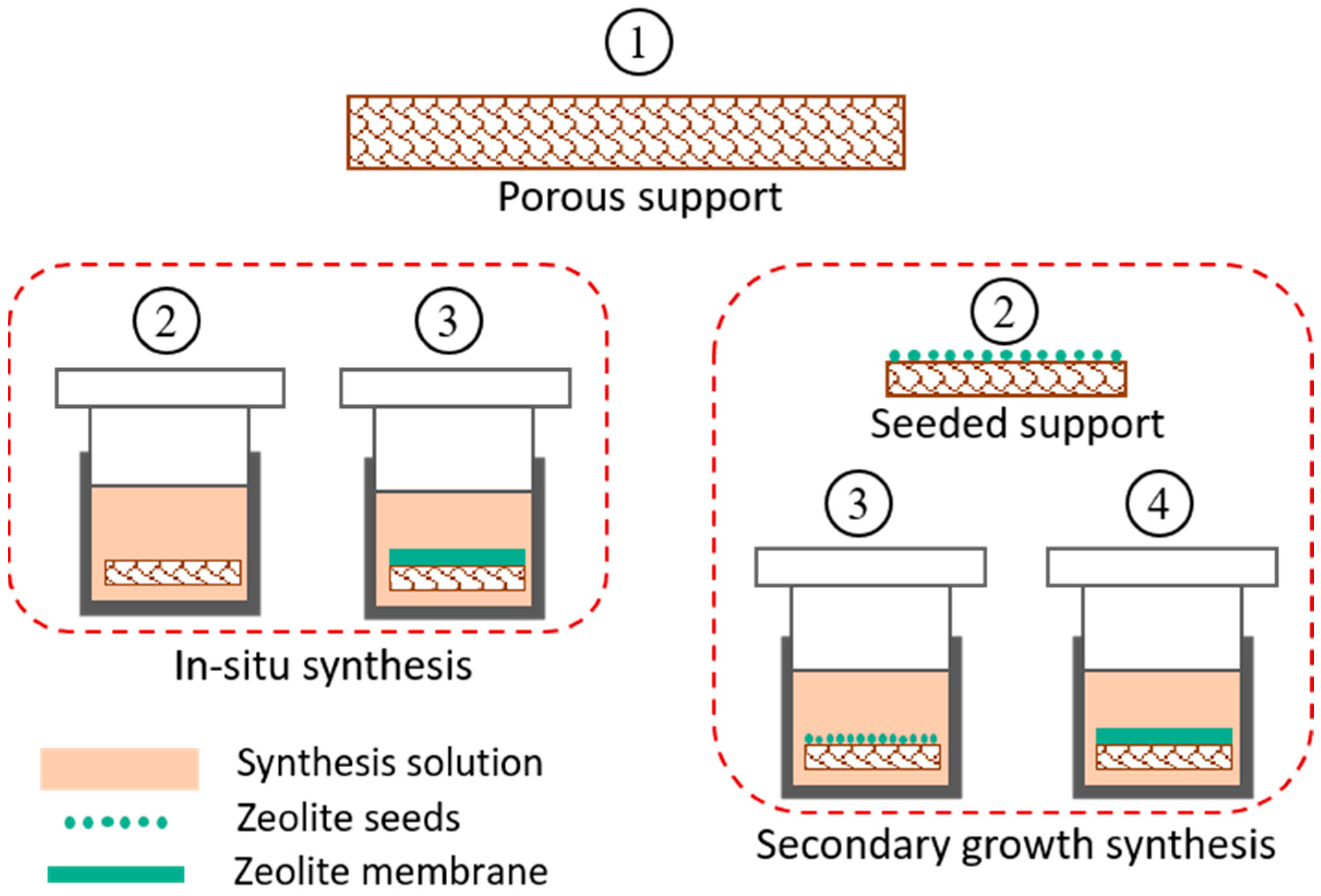
Several methods have been developed for synthesizing zeolite membranes on these supports using in situ crystallization and secondary-growth [257,258,259,260]. Both processes work on the principle of hydrothermal crystallization of zeolite particles on a well-prepared support material. A synthesis solution is prepared by mixing required amounts of aluminate and silicate solutions along with other structural directing agents. These agents upon post calcination are removed from inner cavities of zeolite leaving behind porous crystalline structure [261]. For in-situ crystallization, the support is directly immersed in synthesis solution/gel contained in a Teflon lined stainless steel autoclave and kept at a certain temperature. The zeolite crystals grow on support surface by thermally driven crystallization followed by in situ nucleation [257,258]. This method produces non-uniform zeolite layers and is not reproducible, as nucleation and crystal growth processes happen simultaneously.
The second method of secondary-growth crystallization is the most reliable for producing a uniform zeolite layer by separately performing the nucleation and crystal growth steps [259,260], as shown in Figure 5. Nucleation is done by depositing zeolite nuclei (seeds) on support by dip coating or rubbing, before doing final crystallization. This step is more crucial in the secondary growth method and must be carried out carefully to ensure evenly distributed crystal seeds. Many factors such as seed concentration, seed size, coating cycles, coating time, pH and temperature of seed solution are optimized to prepare an optimized seeded support [262,263]. This seeded support is then subjected to hydrothermal treatment similar to in situ crystallization, which provides the seeds as active sites for further growth of zeolite crystals and hence results in a smooth and uniform layer. After successful deposition of zeolite layer on the support, the prepared membrane is subjected to high temperature calcination to strengthen and stabilize the zeolite layer on the support [22,32].
The secondary growth method is widely used for hydrothermal synthesis of zeolite membranes. There are several synthesis features such as seed size, seed concentration, synthesis time and synthesis temperature, all of which can affect the quality of membrane. During the seeding process, a high concentration of seed suspension could lead to agglomeration of seeds, resulting in increased membrane thickness, while too low a concentration of seed suspension could be unable to fully cover the support [265]. Therefore, optimal seed concentration is required for efficient membrane synthesis. In addition to this, large size seed crystals produce rough membrane surface due to poor crystal intergrowth, however it gives a stronger interaction of the zeolite with its support [266]. On the contrary, small seeds can fill the intercrystallite gaps and give a more uniform surface [267]. To take advantage of both characteristics, multi-layers with different seed sizes can be used instead of single size crystals.
The synthesis of time and temperature can also affect the quality of the final zeolite membrane. The growth of zeolite on seeded support occurs in two steps, namely as nucleation stimulated by seed crystals and intergrowth of crystals to form a final layer. Therefore, insufficient synthesis time can lead to a non-uniform morphology due to the lack of intergrowth of crystals, while prolonged time can result in overgrowth of crystals and hence, a thick membrane layer [268,269]. Similarly, synthesis temperature also controls the quality of final membrane as low temperature favors the slow crystallization compared to nucleation, producing a defect free thin layer [270]. On the other hand, high temperature enables the fast crystallization and produces large size crystals with the advantage of strong support-zeolite interaction [271]. Therefore, a two-step synthesis in a sequence of low and high temperatures can be performed to achieve uniform as well as strong membrane layer [26].
6. Zeolite Membrane Reactors for Methanol Synthesis
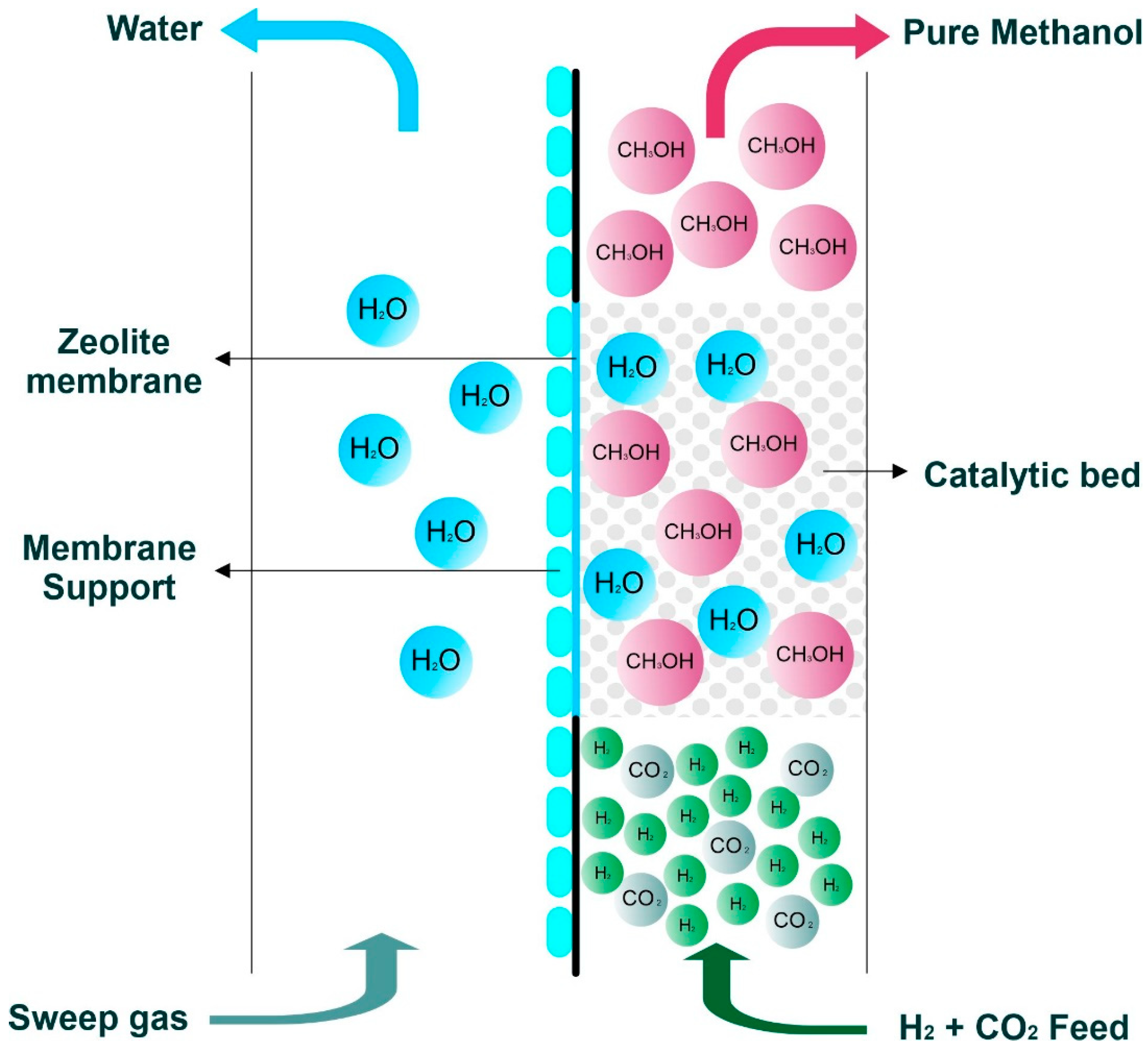
Currently, thermally stable membrane materials are being studied for direct water removal from methanol synthesis reactors [24]. Clean methanol is produced from high-purity captured CO2 and green H2 and at the same time, water is the only impurity emerging from the reaction, with other unreacted gases and product methanol. Therefore, in situ water removal from a reaction mixture of CO2, H2, CH3OH and H2O can be achieved by putting water extraction arrangement in methanol synthesis reactor as shown in Figure 6 [34,272,273,274,275].
In late 1990s, researchers started to capture water from the methanol synthesis mixture by using the available commercial membranes. For example, Nafion membrane was first used by Struis et al. for in situ water removal from methanol synthesis reactor and this showed the feasibility as a membrane reactor for this application [274]. Nevertheless, the disadvantage of the Nafion membrane was the low temperature limitations of 200 °C, whereby it is lower than the optimal methanol synthesis temperature of 250 °C. Subsequently, Chen et al. used a ceramic membrane modified with silicone rubber to have better thermal stability but could achieve only up to 230 °C [275]. Gallucci et al. (2004) successfully developed a zeolite membrane reactor for methanol synthesis from CO2 and H2 at operating conditions similar to the industrial synthesis. Zeolite materials were found to be more favorable for this application due to its high thermal and chemical stabilities. Many researchers have developed studies to produce more efficient zeolite membrane reactor for methanol synthesis [32,37,276,277,278,279].
6.1. Effects of In Situ Water Removal on Process Efficiency
A water-selective zeolite membrane capable of bearing the operating conditions of methanol synthesis reactor was deployed for in situ removal of by-product water [34]. The pores of the zeolite membrane, when filled with water molecules due to its intrinsic hydrophilic nature, can efficiently reject even smaller molecules like H2 from passing through it [32]. This in situ water removal is a breakthrough to overcome the thermodynamic limitations of CO2 conversion to methanol. Subsequently, removal of water directly from the reactor has many direct effects on overall process efficiency in terms of increasing CO2 conversion, increasing methanol yield and purity, as explained in the following sections.
6.1.1. Increasing CO2 Conversion and Methanol Yield
Catalytic conversion of CO2 to methanol is an exothermic reaction producing fewer number of moles in products; for example, four moles of reactants give two moles of products [280]. According to Le Chatelier’s principle, there is a need for suitable conditions to shift the reaction equilibrium to forward side, which conditions are low temperature and high pressure. The extreme conditions of these values result in negative effect on large scale production. For instance, low temperature slows down the reaction kinetics of catalytic reaction, while high pressures make the process more expensive. Therefore, the reaction must be performed at moderate conditions to save the processing time, even though at the expense of single pass equilibrium conversion. Borisut et al. found the optimized operating conditions of CO2 hydrogenation to methanol as 183.6 °C and 57.8 bar along with 40 to 45% CO2 conversion [281]. The unreacted gases are recycled back into the reactor to save raw material cost, while having higher overall conversions. Instead of regulating the temperature and pressure, an alternate method to increase the equilibrium conversion can be used to remove the resultant product from the reaction mixture. As per Le Chatelier’s principle, removal of product species pushes the reaction equilibrium towards a forward direction and hence increases the reactant conversion [273]. This phenomenon is utilized in several membrane reactors to achieve high conversion by selectively removing one of the product species [282,283].
Following this principle, zeolite membranes have been deployed in catalytic membrane reactors for selectively removing water from reaction mixture and hence shifting the equilibrium towards forward direction. In this way, both CO2 conversion and reaction rate can be increased, even at high temperature and lower pressure, which can even surpass the thermodynamic equilibrium values, as shown in Table 6. Li et al. removed overall products such as methanol and water by using non-selective hydrophilic zeolite membrane and achieved 60% conversion of CO2 at 220 °C and 32 bar pressure [33]. Yue et al. used bifunctional catalytic membrane and obtained 100% methanol selectivity along with 36.1% CO2 conversion operating at 300 °C and 30 bar [34]. Similarly, Seshimo et al. used water selective Si-rich LTA membrane and reached good CO2 conversion of 60% at 220 °C and 40 bars of pressure [37]. It was shown by the authors that by increasing the Si content the hydrophilicity of membrane can be increased. Li et al. achieved higher CO2 conversion (61.4%) as compared to a traditional packed-bed reactor (23%) which was near to the equilibrium value at 250 °C temperature and 35 bar pressure [32]. Consequently, Tian et al. used Cu–ZnO@LTA membrane reactor for CO2 hydrogenation and achieved about double of CO2 conversion (49.1%) as compared to packed-bed reactor (26.2%) at similar operating conditions of 250 °C and 30 bar [36]. In light of these findings, membrane reactors are a very promising opportunity for having CO2 conversion and methanol selectivity above thermodynamic limitations for methanol synthesis.
6.1.2. In Situ Methanol Purification
By removing the water from methanol synthesis reactor, one can decrease a huge load from downstream methanol purification which is mainly done by distillation [32]. To get high purity of methanol with a simple process, it is necessary to choose a membrane reactor that screens out only H2O molecules. Seshimo et al. reported the production of 95% pure methanol using Si-rich LTA-Zeolite membrane [37]. Recently, a higher methanol purity was reported by Li et al. to produce 95.9% pure methanol by using water selective membrane reactor [32]. Consequently, the methanol production with high purity was obtained compared to that traditional packed bed reactor which was only 53.4%, using similar operating conditions.
This in-situ methanol purification by using a water-selective membrane reactor incorporated with zeolite membrane has the advantage of decreasing the load on the final distillation unit. In this way, a relatively smaller distillation unit is required to remove the remaining 5 to 10% of water impurities [32]. This strategy not only saves the plant energy but also cuts down the capital investment by shrinking the equipment footprint. This new technology could be a way forward towards obtaining further high purity of methanol from membrane reactor by developing more efficient membrane materials. Furthermore, this methanol synthesis technology has been tested on the laboratory scale and has potential for further research and development for large scale implementation.
7. Conclusions and Outlook for Future Work
The potential of clean methanol (e-methanol) to restrain the usage of fossil fuels to decarbonize the earth’s atmosphere is explained in this paper. Because e-methanol is derived from captured CO2 and green H2 using renewable energy, therefore, its manufacturing process has to be effectively of zero impact on the environment. On the consumption of methanol, only CO2 and H2O are the end products, while the same amount of emitted CO2 will be captured again for methanol synthesis, which closes the loop of CO2 to achieve net zero emissions. Due to the rapidly changing climate and constantly increasing global temperature, many countries are trying to replace the fossil fuels with renewable fuels and green H2. Methanol has also proved to be a feasible medium for long term storage of green H2 even though it is difficult to handle and store due to its gaseous nature. The major bottleneck in fully switching on the methanol economy is the uninterrupted supply of green H2. Currently, the level of green H2 production is not enough to fulfil the requirement of mass production of e-methanol. Therefore, more work on green H2 production is required to fill the supply and demand gap. At the moment, the cost of e-methanol is much higher than market price of conventional methanol. The main factor affecting the e-methanol cost is green H2, as it accounts for more than 70% of the total production cost. Hence, more research is required for low-cost production of clean H2 to overcome fossil fuel.
Besides the availability of cheaper raw materials, production costs can be significantly reduced by improving the overall process efficiency. The process efficiency of methanol production from CO2 hydrogenation is restricted by thermodynamic limitations. This limitation can be overcome with the application of zeolite membrane inside of methanol synthesis reactor for in situ removal of by-product water. High CO2 conversions and methanol selectivity as compared to traditional reactors were achieved in this way. These zeolite membrane reactors for methanol production are still on laboratory scale and further research is needed for their applicability on large scale methanol production. When it comes to large scale applications, creating a membrane with high stability and large surface area, efficient process control schemes and pilot scale studies are some important areas which are still needed to be explored. Additionally, more efficient membrane materials are required to achieve even higher methanol purity from synthesis reactor to completely eliminate the downstream distillation process. Furthermore, small modular designs of methanol production units coupled with green H2 supply and recycled CO2 could be a possible pathway to minimize the cost of transportation and large-scale storage.
Overall, such an effort in promoting the technological advancement for the e-methanol production will ensure sustainable development. Shifting toward producing e-methanol could also help in achieving the UN Sustainable Development Goals (SDGs), particularly SDG 7 on affordable and clean energy as well as SDG 13 on climate action.
Author Contributions
Conceptualization, A.U.; investigation, A.U., N.A.H., M.F.R. and M.U.M.J.; resources, A.U. and M.F.R.; writing—original draft preparation, A.U.; writing—review and editing, A.U., N.A.H., M.F.R. and M.U.M.J.; visualization, M.U.M.J.; supervision, N.A.H. All authors have read and agreed to the published version of the manuscript.
Funding
The authors would like to acknowledge the Universiti Malaya- Research University Grant (GPF058B-2020) for funding this research.
Conflicts of Interest
The authors declare no conflict of interest.
References
- IEA. Global Electricity Demand is Growing Faster than Renewables, Driving Strong Increase in Generation from Fossil Fuels. 2021. Available online: https://www.iea.org/news/global-electricity-demand-is-growing-faster-than-renewables-driving-strong-increase-in-generation-from-fossil-fuels (accessed on 16 December 2022).
- ExxonMobil. Energy Demand: Three Drivers. 2022. Available online: https://corporate.exxonmobil.com/energy-and-innovation/outlook-for-energy/energy-demand (accessed on 16 December 2022).
- Shahbaz, M.; Topcu, B.A.; Sarıgül, S.S.; Vo, X.V. The effect of financial development on renewable energy demand: The case of developing countries. Renew. Energy 2021, 178, 1370–1380. [Google Scholar] [CrossRef]
- Gielen, D.; Gorini, R.; Leme, R.; Prakash, G.; Wagner, N.; Janeiro, L.; Collins, S.; Kadir, M.; Asmelash, E.; Ferroukhi, R. World Energy Transitions Outlook: 1.5° C Pathway; International Renewable Energy Agency (IRENA): Abu Dhabi, United Arab Emirates, 2021. [Google Scholar]
- Rogelj, J.; Popp, A.; Calvin, K.V.; Luderer, G.; Emmerling, J.; Gernaat, D.; Fujimori, S.; Strefler, J.; Hasegawa, T.; Marangoni, G.; et al. Scenarios towards limiting global mean temperature increase below 1.5 °C. Nat. Clim. Change 2018, 8, 325–332. [Google Scholar] [CrossRef]
- Ou, Y.; Roney, C.; Alsalam, J.; Calvin, K.; Creason, J.; Edmonds, J.; Fawcett, A.A.; Kyle, P.; Narayan, K.; O’Rourke, P.; et al. Deep mitigation of CO2 and non-CO2 greenhouse gases toward 1.5 °C and 2 °C futures. Nat. Commun. 2021, 12, 6245. [Google Scholar] [CrossRef]
- The Paris Agreement. In Proceedings of the 2015 Paris Climate Change Conference: COP21, Paris, France, 30 November–12 December 2015.
- United Nations. Adoption of the Paris Agreement. 2015. Available online: https://unfccc.int/resource/docs/2015/cop21/eng/l09r01.pdf (accessed on 16 December 2022).
- United Nations. The Sustainable Development Goals Report; United Nations Statistics Division: New York, NY, USA, 2022. [Google Scholar]
- U.S. Energy Information Administration. EIA Projects Nearly 50% Increase in World Energy Use by 2050, Led by Growth in Renewables. 2021. Available online: https://www.eia.gov/todayinenergy/detail.php?id=49876 (accessed on 16 December 2022).
- Cui, X.; Kær, S.K.; Nielsen, M.P. Energy analysis and surrogate modeling for the green methanol production under dynamic operating conditions. Fuel 2021, 307, 121924. [Google Scholar] [CrossRef]
- Ra, E.C.; Kim, K.Y.; Kim, E.H.; Lee, H.; An, K.; Lee, J.S. Recycling Carbon Dioxide through Catalytic Hydrogenation: Recent Key Developments and Perspectives. ACS Catal. 2020, 10, 11318–11345. [Google Scholar] [CrossRef]
- Alsarhan, L.M.; Alayyar, A.S.; Alqahtani, N.B.; Khdary, N.H. Circular Carbon Economy (CCE): A Way to Invest CO2 and Protect the Environment, a Review. Sustainability 2021, 13, 11625. [Google Scholar] [CrossRef]
- Cuéllar-Franca, R.M.; Azapagic, A. Carbon capture, storage and utilisation technologies: A critical analysis and comparison of their life cycle environmental impacts. J. CO2 Util. 2015, 9, 82–102. [Google Scholar] [CrossRef]
- Oner, O.; Dincer, I. Development and assessment of a hybrid biomass and wind energy-based system for cleaner production of methanol with electricity, heat and freshwater. J. Clean. Prod. 2022, 367, 132967. [Google Scholar] [CrossRef]
- Kätelhön, A.; Meys, R.; Deutz, S.; Suh, S.; Bardow, A. Climate change mitigation potential of carbon capture and utilization in the chemical industry. Proc. Natl. Acad. Sci. USA 2019, 116, 11187–11194. [Google Scholar] [CrossRef]
- Iribarren, D.; Calvo-Serrano, R.; Martín-Gamboa, M.; Galán-Martín, A.; Guillén-Gosálbez, G. Social life cycle assessment of green methanol and benchmarking against conventional fossil methanol. Sci. Total. Environ. 2022, 824, 153840. [Google Scholar] [CrossRef]
- Hydrogen-Central. Cement Australia Partners with Mitsubishi Gas Chemical Company for Green Methanol, from Hydrogen, Trial at Gladstone Cement Plant, Hydrogen Central. 2022. Available online: https://hydrogen-central.com/cement-australia-partners-mitsubishi-gas-chemical-company-green-methanol-hydrogen-trial-gladstone-cement-plant/ (accessed on 17 November 2022).
- Jiang, X.; Nie, X.; Guo, X.; Song, C.; Chen, J.G. Recent advances in carbon dioxide hydrogenation to methanol via heterogeneous catalysis. Chem. Rev. 2020, 120, 7984–8034. [Google Scholar] [CrossRef]
- Bano, S.; Mahmood, A.; Lee, K.-H. Vapor Permeation Separation of Methanol–Water Mixtures: Effect of Experimental Conditions. Ind. Eng. Chem. Res. 2013, 52, 10450–10459. [Google Scholar] [CrossRef]
- Hu, K.; Nie, J.; Liu, J.; Zheng, J. Separation of methanol from methanol/water mixtures with pervaporation hybrid membranes. J. Appl. Polym. Sci. 2013, 128, 1469–1475. [Google Scholar] [CrossRef]
- Arepalli, D.; Rehman, A.-U.; Kim, M.-Z.; Alam, S.F.; Cho, C.-H. Optimal synthesis of nanosize seeds for secondary growth of high performance hydroxy-sodalite (H-SOD) zeolite membranes for small gas and water separations. Microporous Mesoporous Mater. 2021, 329, 111451. [Google Scholar] [CrossRef]
- Mahmood, A.; Bano, S.; Kim, S.-G.; Lee, K.-H. Water–methanol separation characteristics of annealed SA/PVA complex membranes. J. Membr. Sci. 2012, 415–416, 360–367. [Google Scholar] [CrossRef]
- Li, Z.; Deng, Y.; Dewangan, N.; Hu, J.; Wang, Z.; Tan, X.; Liu, S.; Kawi, S. High Temperature Water Permeable Membrane Reactors for CO2 Utilization. Chem. Eng. J. 2021, 420, 129834. [Google Scholar] [CrossRef]
- Kreethawate, L.; Larpkiattaworn, S.; Phonnoi, J.; Tong-On, S. Zeolite layer synthesized on porous alumina substrate for water/methanol separation. Surf. Coatings Technol. 2016, 306, 45–48. [Google Scholar] [CrossRef]
- Gao, X.; Deng, S.; Kawi, S. Zeolite-based catalytic membrane reactors for thermo-catalytic conversion of CO2. iScience 2022, 25, 105343. [Google Scholar] [CrossRef]
- Gorbe, J.; Lasobras, J.; Francés, E.; Herguido, J.; Menéndez, M.; Kumakiri, I.; Kita, H. Preliminary study on the feasibility of using a zeolite A membrane in a membrane reactor for methanol production. Sep. Purif. Technol. 2018, 200, 164–168. [Google Scholar] [CrossRef]
- Feenstra, M.; Zubeir, L.; van der Veek, M.; Ramirez, A.; Goetheer, E. Separation Enhanced Methanol Synthesis from CO2 and H2. In Proceedings of the 16th Greenhouse Gas Control Technologies Conference (GHGT-16), Lyon, France, 23–24 October 2022. [Google Scholar]
- Abashar, M.; Al-Rabiah, A. Highly efficient CO2 hydrogenation to methanol via in-situ condensation and sorption in a novel multi-stage circulating fast fluidized bed reactor. Chem. Eng. J. 2022, 439, 135628. [Google Scholar] [CrossRef]
- Din, I.U.; Shaharun, M.S.; Alotaibi, M.A.; Alharthi, A.I.; Naeem, A. Recent developments on heterogeneous catalytic CO2 reduction to methanol. J. CO2 Util. 2019, 34, 20–33. [Google Scholar] [CrossRef]
- Leonzio, G. Methanol Synthesis: Optimal Solution for a Better Efficiency of the Process. Processes 2018, 6, 20. [Google Scholar] [CrossRef]
- Li, H.; Qiu, C.; Ren, S.; Dong, Q.; Zhang, S.; Zhou, F.; Liang, X.; Wang, J.; Li, S.; Yu, M. Na+-gated water-conducting nanochannels for boosting CO2 conversion to liquid fuels. Science 2020, 367, 667–671. [Google Scholar] [CrossRef] [PubMed]
- Li, Z.; Tsotsis, T.T. Methanol synthesis in a high-pressure membrane reactor with liquid sweep. J. Membr. Sci. 2019, 570–571, 103–111. [Google Scholar] [CrossRef]
- Yue, W.; Li, Y.; Wei, W.; Jiang, J.; Caro, J.; Huang, A. Highly Selective CO2 Conversion to Methanol in a Bifunctional Zeolite Catalytic Membrane Reactor. Angew. Chem. Int. Ed. 2021, 60, 18289–18294. [Google Scholar] [CrossRef]
- Deng, Y.; Li, Z.; Chen, T.; Bian, Z.; Lim, K.; Dewangan, N.; Haw, K.G.; Wang, Z.; Kawi, S. Low-cost and facile fabrication of defect-free water permeable membrane for CO2 hydrogenation to methanol. Chem. Eng. J. 2022, 435, 133554. [Google Scholar] [CrossRef]
- Tian, C.; Huang, A. Synthesis of a Cu/Zn-BTC@LTA derivatived Cu–ZnO@LTA membrane reactor for CO2 hydrogenation. J. Memb. Sci. 2022, 662, 121010. [Google Scholar] [CrossRef]
- Seshimo, M.; Liu, B.; Lee, H.; Yogo, K.; Yamaguchi, Y.; Shigaki, N.; Mogi, Y.; Kita, H.; Nakao, S.-I. Membrane Reactor for Methanol Synthesis Using Si-Rich LTA Zeolite Membrane. Membranes 2021, 11, 505. [Google Scholar] [CrossRef]
- Dalena, F.; Senatore, A.; Marino, A.; Gordano, A.; Basile, M.; Basile, A. Chapter 1—Methanol Production and Applications: An Overview. In Methanol; Basile, A., Dalena, F., Eds.; Elsevier: Amsterdam, The Netherlands, 2018; pp. 3–28. [Google Scholar] [CrossRef]
- Fernández, L. Production Capacity of Methanol Worldwide from 2018 to 2021—Statista. 2022. Available online: https://0-www-statista-com.brum.beds.ac.uk/statistics/1065891/global-methanol-production-capacity/#statisticContainer (accessed on 24 November 2022).
- Dalena, F.; Senatore, A.; Basile, M.; Knani, S.; Basile, A.; Iulianelli, A. Advances in Methanol Production and Utilization, with Particular Emphasis toward Hydrogen Generation via Membrane Reactor Technology. Membranes 2018, 8, 98. [Google Scholar] [CrossRef] [Green Version]
- Riaz, A.; Zahedi, G.; Klemeš, J.J. A review of cleaner production methods for the manufacture of methanol. J. Clean. Prod. 2013, 57, 19–37. [Google Scholar] [CrossRef]
- Al Hashar, D. Renewable Methanol Production Using Captured Carbon Dioxide and Hydrogen Generated through Water-Splitting. Engineering 2022, 14, 339–359. [Google Scholar] [CrossRef]
- Cifre, P.G.; Badr, O. Renewable hydrogen utilisation for the production of methanol. Energy Convers. Manag. 2007, 48, 519–527. [Google Scholar] [CrossRef]
- González-Garay, A.; Frei, M.S.; Al-Qahtani, A.; Mondelli, C.; Guillén-Gosálbez, G.; Pérez-Ramírez, J. Plant-to-planet analysis of CO2-based methanol processes. Energy Environ. Sci. 2019, 12, 3425–3436. [Google Scholar] [CrossRef]
- Olah, G.A.; Goeppert, A.; Prakash, G.K.S. Chemical Recycling of Carbon Dioxide to Methanol and Dimethyl Ether: From Greenhouse Gas to Renewable, Environmentally Carbon Neutral Fuels and Synthetic Hydrocarbons. J. Org. Chem. 2009, 74, 487–498. [Google Scholar] [CrossRef] [PubMed]
- Goeppert, A.; Czaun, M.; Jones, J.-P.; Prakash, G.K.S.; Olah, G.A. Recycling of carbon dioxide to methanol and derived products—Closing the loop. Chem. Soc. Rev. 2014, 43, 7995–8048. [Google Scholar] [CrossRef] [PubMed]
- Shamsul, N.S.; Kamarudin, S.K.; Rahman, N.A.; Kofli, N.T. An overview on the production of bio-methanol as potential renewable energy. Renew. Sustain. Energy Rev. 2014, 33, 578–588. [Google Scholar] [CrossRef]
- Dias, V.; Pochet, M.; Contino, F.; Jeanmart, H. Energy and Economic Costs of Chemical Storage. Front. Mech. Eng. 2020, 6, 00021. [Google Scholar] [CrossRef]
- Armaroli, N.; Balzani, V. The hydrogen issue. ChemSusChem 2011, 4, 21–36. [Google Scholar] [CrossRef]
- U.S. Department of Energy. Hydrogen Storage. Available online: https://www.energy.gov/eere/fuelcells/hydrogen-storage (accessed on 27 October 2022).
- Modi, P.; Aguey-Zinsou, K.-F. Room Temperature Metal Hydrides for Stationary and Heat Storage Applications: A Review. Front. Energy Res. 2021, 9, 616115. [Google Scholar] [CrossRef]
- Tibdewal, S.; Saxena, U.; Gurumoorthy, A. Hydrogen economy vs. Methanol economy. Int. J. Chem. Sci. 2014, 12, 1478–1486. [Google Scholar]
- Bunyakiat, K.; Makmee, S.; Sawangkeaw, R.; Ngamprasertsith, S. Continuous Production of Biodiesel via Transesterification from Vegetable Oils in Supercritical Methanol. Energy Fuels 2006, 20, 812–817. [Google Scholar] [CrossRef]
- Semelsberger, T.A.; Borup, R.L.; Greene, H.L. Dimethyl ether (DME) as an alternative fuel. J. Power Sources 2006, 156, 497–511. [Google Scholar] [CrossRef]
- Hosseininejad, S.; Afacan, A.; Hayes, R. Catalytic and kinetic study of methanol dehydration to dimethyl ether. Chem. Eng. Res. Des. 2012, 90, 825–833. [Google Scholar] [CrossRef]
- Methanol Institute. Energy. Available online: https://www.methanol.org/Energy/ (accessed on 3 November 2022).
- Habibic, A. World’s 1st Large-Scale E-Methanol Project to Fuel Maersk’s Boxships. Offshore Energy. 2022. Available online: https://www.offshore-energy.biz/worlds-1st-large-scale-e-methanol-project-to-fuel-maersks-boxships/ (accessed on 21 November 2022).
- Andersson, J.; Grönkvist, S. Large-scale storage of hydrogen. Int. J. Hydrogen Energy 2019, 44, 11901–11919. [Google Scholar] [CrossRef]
- Take, T.; Tsurutani, K.; Umeda, M. Hydrogen production by methanol–water solution electrolysis. J. Power Sources 2007, 164, 9–16. [Google Scholar] [CrossRef]
- Menia, S.; Tebibel, H.; Lassouane, F.; Khellaf, A.; Nouicer, I. Hydrogen production by methanol aqueous electrolysis using photovoltaic energy: Algerian potential. Int. J. Hydrogen Energy 2017, 42, 8661–8669. [Google Scholar] [CrossRef]
- Tuomi, S.; Santasalo-Aarnio, A.; Kanninen, P.; Kallio, T. Hydrogen production by methanol–water solution electrolysis with an alkaline membrane cell. J. Power Sources. 2013, 229, 32–35. [Google Scholar] [CrossRef]
- Vázquez, F.V.; Simell, P.; Pennanen, J.; Lehtonen, J. Reactor design and catalysts testing for hydrogen production by methanol steam reforming for fuel cells applications. Int. J. Hydrogen Energy 2016, 41, 924–935. [Google Scholar] [CrossRef]
- Palo, D.R.; Dagle, R.A.; Holladay, J.D. Methanol Steam Reforming for Hydrogen Production. Chem. Rev. 2007, 107, 3992–4021. [Google Scholar] [CrossRef]
- Cortright, R.D.; Davda, R.R.; Dumesic, J.A. Hydrogen from catalytic reforming of biomass-derived hydrocarbons in liquid water. Nature 2002, 418, 964–967. [Google Scholar] [CrossRef]
- Zoppi, G.; Pipitone, G.; Gruber, H.; Weber, G.; Reichhold, A.; Pirone, R.; Bensaid, S. Aqueous phase reforming of pilot-scale Fischer-Tropsch water effluent for sustainable hydrogen production. Catal. Today. 2021, 367, 239–247. [Google Scholar] [CrossRef]
- Ranjekar, A.M.; Yadav, G.D. Steam Reforming of Methanol for Hydrogen Production: A Critical Analysis of Catalysis, Processes, and Scope. Ind. Eng. Chem. Res. 2021, 60, 89–113. [Google Scholar] [CrossRef]
- Stekrova, M.; Rinta-Paavola, A.; Karinen, R. Hydrogen production via aqueous-phase reforming of methanol over nickel modified Ce, Zr and La oxide supports. Catal. Today. 2018, 304, 143–152. [Google Scholar] [CrossRef]
- Pethaiah, S.S.; Sadasivuni, K.K.; Jayakumar, A.; Ponnamma, D.; Tiwary, C.S.; Sasikumar, G. Methanol Electrolysis for Hydrogen Production Using Polymer Electrolyte Membrane: A Mini-Review. Energies 2020, 13, 5879. [Google Scholar] [CrossRef]
- Ju, H.; Giddey, S.; S.Badwal, P.S.; Mulder, R.J.; Gengenbach, T.R. Methanol-water co-electrolysis for sustainable hydrogen production with PtRu/C-SnO2 electro-catalyst. Ionics 2018, 24, 2367–2378. [Google Scholar] [CrossRef]
- Bahrami, H.; Faghri, A. Review and advances of direct methanol fuel cells: Part II: Modeling and numerical simulation. J. Power Sources 2013, 230, 303–320. [Google Scholar] [CrossRef]
- Radenahmad, N.; Afif, A.; Petra, P.I.; S.Rahman, M.H.; S.-Eriksson, G.; Azad, A.K. Proton-conducting electrolytes for direct methanol and direct urea fuel cells—A state-of-the-art review. Renew. Sustain. Energy Rev. 2016, 57, 1347–1358. [Google Scholar] [CrossRef]
- Xia, Z.; Zhang, X.; Sun, H.; Wang, S.; Sun, G. Recent advances in multi-scale design and construction of materials for direct methanol fuel cells. Nano Energy 2019, 65, 104048. [Google Scholar] [CrossRef]
- Toshiba. Toshiba Launches Direct Methanol Fuel Cell in Japan as External Power. 2009. Available online: https://www.global.toshiba/ww/news/corporate/2009/10/pr2201.html (accessed on 9 November 2022).
- Lange, J.-P. Methanol synthesis: A short review of technology improvements. Catal. Today 2001, 64, 3–8. [Google Scholar] [CrossRef]
- Van Bennekom, J.; Venderbosch, R.; Winkelman, J.; Wilbers, E.; Assink, D.; Lemmens, K.; Heeres, H. Methanol synthesis beyond chemical equilibrium. Chem. Eng. Sci. 2013, 87, 204–208. [Google Scholar] [CrossRef]
- Collodi, G.; Azzaro, G.; Ferrari, N.; Santos, S. Demonstrating Large Scale Industrial CCS through CCU—A Case Study for Methanol Production. Energy Procedia 2017, 114, 122–138. [Google Scholar] [CrossRef]
- Bellotti, D.; Rivarolo, M.; Magistri, L.; Massardo, A.F. Feasibility study of methanol production plant from hydrogen and captured carbon dioxide. J. CO2 Util. 2017, 21, 132–138. [Google Scholar] [CrossRef]
- Mbatha, S.; Everson, R.C.; Musyoka, N.M.; Langmi, H.W.; Lanzini, A.; Brilman, W. Power-to-methanol process: A review of electrolysis, methanol catalysts, kinetics, reactor designs and modelling, process integration, optimisation, and techno-economics. Sustain. Energy Fuels. 2021, 5, 3490–3569. [Google Scholar] [CrossRef]
- Chehade, Z.; Mansilla, C.; Lucchese, P.; Hilliard, S.; Proost, J. Review and analysis of demonstration projects on power-to-X pathways in the world. Int. J. Hydrogen Energy 2019, 44, 27637–27655. [Google Scholar] [CrossRef]
- Bellotti, D.; Rivarolo, M.; Magistri, L. Clean fuels synthesis from green hydrogen: A techno-economic comparative analysis. E3S Web Conf. 2021, 238, 03001. [Google Scholar] [CrossRef]
- Zhang, Y.; Wan, L.; Guan, J.; Xiong, Q.; Zhang, S.; Jin, X. A Review on Biomass Gasification: Effect of Main Parameters on Char Generation and Reaction. Energy Fuels 2020, 34, 13438–13455. [Google Scholar] [CrossRef]
- Sari, D. Methane capture installation for greenhouse gasses emission reduction in palm oil mill. J. Adv. Res. Dyn. Control. Syst. 2019, 11, 459–464. [Google Scholar] [CrossRef]
- Lam, M.K.; Lee, K.T. Renewable and sustainable bioenergies production from palm oil mill effluent (POME): Win–win strategies toward better environmental protection. Biotechnol. Adv. 2011, 29, 124–141. [Google Scholar] [CrossRef]
- Centi, G.; Perathoner, S. Opportunities and prospects in the chemical recycling of carbon dioxide to fuels. Catal. Today. 2009, 148, 191–205. [Google Scholar] [CrossRef]
- Do, N.T.Q.; Haag, S.; Castillo-Weltter, F.; Gunther, A. Flexible and Sustainable Methanol Production Including Option with Green Hydrogen. In Proceedings of the 14th International Symposium on Process System Engineering, Kyoto, Japan, 19–23 June 2022; Yamashita, Y., Kano, M., Eds.; pp. 775–780. [Google Scholar] [CrossRef]
- Lonis, F.; Tola, V.; Cau, G. Assessment of integrated energy systems for the production and use of renewable methanol by water electrolysis and CO2 hydrogenation. Fuel 2021, 285, 119160. [Google Scholar] [CrossRef]
- Liquid Wind. Flagships. Available online: https://www.liquidwind.se/flagships (accessed on 19 December 2022).
- Pekic, S. Ørsted Joins Liquid Wind on FlagshipONE E-Methanol Project. 2022. Available online: https://www.offshore-energy.biz/orsted-joins-liquid-wind-on-flagshipone-e-methanol-project/ (accessed on 25 December 2022).
- Ji, M.; Wang, J. Review and comparison of various hydrogen production methods based on costs and life cycle impact assessment indicators. Int. J. Hydrogen Energy 2021, 46, 38612–38635. [Google Scholar] [CrossRef]
- Newborough, M.; Cooley, G. Developments in the global hydrogen market: Electrolyser deployment rationale and renewable hydrogen strategies and policies. Fuel Cells Bull. 2020, 2020, 16–22. [Google Scholar] [CrossRef]
- IRENA. Policies for Green Hydrogen. 2020. Available online: https://www.irena.org/Energy-Transition/Policy/Policies-for-green-hydrogen (accessed on 31 October 2022).
- Gerloff, N. Comparative Life-Cycle-Assessment analysis of three major water electrolysis technologies while applying various energy scenarios for a greener hydrogen production. J. Energy Storage 2021, 43, 102759. [Google Scholar] [CrossRef]
- Beswick, R.R.; Oliveira, A.M.; Yan, Y. Does the Green Hydrogen Economy Have a Water Problem? ACS Energy Lett. 2021, 6, 3167–3169. [Google Scholar] [CrossRef]
- Palmer, G.; Roberts, A.; Hoadley, A.; Dargaville, R.; Honnery, D. Life-cycle greenhouse gas emissions and net energy assessment of large-scale hydrogen production via electrolysis and solar PV. Energy Environ. Sci. 2021, 14, 5113–5131. [Google Scholar] [CrossRef]
- Papadias, D.D.; J.-Peng, K.; Ahluwalia, R.K. Hydrogen carriers: Production, transmission, decomposition, and storage. Int. J. Hydrogen Energy 2021, 46, 24169–24189. [Google Scholar] [CrossRef]
- U.S. Department of Energy. Hydrogen Production: Electrolysis. Available online: https://www.energy.gov/eere/fuelcells/hydrogen-production-electrolysis (accessed on 27 October 2022).
- Brauns, J.; Turek, T. Alkaline Water Electrolysis Powered by Renewable Energy: A Review. Processes 2020, 8, 248. [Google Scholar] [CrossRef]
- Kumar, S.S.; Himabindu, V. Hydrogen production by PEM water electrolysis—A review. Mater. Sci. Energy Technol. 2019, 2, 442–454. [Google Scholar] [CrossRef]
- Maric, R.; Yu, H. Proton Exchange Membrane Water Electrolysis as a Promising Technology for Hydrogen Production and Energy Storage. In Nanostructures in Energy Generation, Transmission and Storage; Fedorenko, Y., Ed.; IntechOpen: Rijeka, Croatia, 2018; p. 6. [Google Scholar] [CrossRef] [Green Version]
- Tajuddin, A.A.H.; Wakisaka, M.; Ohto, T.; Yu, Y.; Fukushima, H.; Tanimoto, H.; Li, X.; Misu, Y.; Jeong, S.; Fujita, J.; et al. Corrosion-resistant and high-entropic non-noble-metal electrodes for oxygen evolution in acidic media. Adv. Mater. 2022, 35, 2207466. [Google Scholar] [CrossRef]
- Hu, C.; Zhang, L.; Gong, J. Recent progress made in the mechanism comprehension and design of electrocatalysts for alkaline water splitting. Energy Environ. Sci. 2019, 12, 2620–2645. [Google Scholar] [CrossRef]
- Wu, J.; Myung, J.; Ding, D.; Zhu, T. Editorial: High Temperature Solid Oxide Cells. Front. Chem. 2021, 9, 719826. [Google Scholar] [CrossRef] [PubMed]
- Brisse, A.; Schefold, J.; Zahid, M. High temperature water electrolysis in solid oxide cells. Int. J. Hydrogen Energy 2008, 33, 5375–5382. [Google Scholar] [CrossRef]
- Wang, S.; Lu, A.; C.-Zhong, J. Hydrogen production from water electrolysis: Role of catalysts. Nano Converg. 2021, 8, 4. [Google Scholar] [CrossRef] [PubMed]
- Ishihara, T.; Kanno, T. Steam electrolysis using LaGaO3 based perovskite electrolyte for recovery of unused heat energy. ISIJ Int. 2010, 50, 1291–1295. [Google Scholar] [CrossRef]
- Singh, B.; Ghosh, S.; Aich, S.; Roy, B. Low temperature solid oxide electrolytes (LT-SOE): A review. J. Power Sources 2017, 339, 103–135. [Google Scholar] [CrossRef]
- Nechache, A.; Hody, S. Alternative and innovative solid oxide electrolysis cell materials: A short review. Renew. Sustain. Energy Rev. 2021, 149, 111322. [Google Scholar] [CrossRef]
- Sunfire. Successful Test Operation of the World’s Largest High-Temperature Electrolysis Module. 2021. Available online: https://www.sunfire.de/en/news/detail/successful-test-operation-of-the-worlds-largest-high-temperature-electrolysis-module (accessed on 25 December 2022).
- Wang, Z.; Gu, Y.; Wang, L. Revisiting solar hydrogen production through photovoltaic-electrocatalytic and photoelectrochemical water splitting. Front. Energy 2021, 15, 596–599. [Google Scholar] [CrossRef]
- U.S. Department of Energy. Hydrogen Production: Photoelectrochemical Water Splitting. Available online: https://www.energy.gov/eere/fuelcells/hydrogen-production-photoelectrochemical-water-splitting (accessed on 1 November 2022).
- Grimes, C.A.; Varghese, O.K.; Ranjan, S. Photovoltaic—Electrolysis Cells. In Light, Water, Hydrogen: The Solar Generation of Hydrogen by Water Photoelectrolysis; Grimes, C.A., Varghese, O.K., Ranjan, S., Eds.; Springer: Boston, MA, USA, 2008; pp. 485–516. [Google Scholar] [CrossRef]
- Takanabe, K. Photocatalytic Water Splitting: Quantitative Approaches toward Photocatalyst by Design. ACS Catal. 2017, 7, 8006–8022. [Google Scholar] [CrossRef]
- Takata, T.; Domen, K. Particulate Photocatalysts for Water Splitting: Recent Advances and Future Prospects. ACS Energy Lett. 2019, 4, 542–549. [Google Scholar] [CrossRef]
- Li, Y.; S.Tsang, C.E. Recent progress and strategies for enhancing photocatalytic water splitting. Mater. Today Sustain. 2020, 9, 100032. [Google Scholar] [CrossRef]
- Bie, C.; Wang, L.; Yu, J. Challenges for photocatalytic overall water splitting. Chem 2022, 8, 1567–1574. [Google Scholar] [CrossRef]
- Li, R.; Li, C. Chapter One—Photocatalytic Water Splitting on Semiconductor-Based Photocatalysts. In Advances in Catalysis; Song, C., Ed.; Academic Press: Cambridge, MA, USA, 2017; pp. 1–57. [Google Scholar] [CrossRef]
- Wang, Z.; Luo, Y.; Hisatomi, T.; J.Vequizo, J.M.; Suzuki, S.; Chen, S.; Nakabayashi, M.; Lin, L.; Pan, Z.; Kariya, N.; et al. Sequential cocatalyst decoration on BaTaO2N towards highly-active Z-scheme water splitting. Nat. Commun. 2021, 12, 1005. [Google Scholar] [CrossRef] [PubMed]
- García-Sánchez, A.; Gomez-Mendoza, M.; Barawi, M.; Villar-Garcia, I.J.; Liras, M.; Gándara, F.; O’Shea, V.A.D.L.P. Fundamental Insights into Photoelectrocatalytic Hydrogen Production with a Hole-Transport Bismuth Metal–Organic Framework. J. Am. Chem. Soc. 2020, 142, 318–326. [Google Scholar] [CrossRef] [PubMed]
- Mehtab, A.; Alshehri, S.M.; Ahmad, T. Photocatalytic and Photoelectrocatalytic Water Splitting by Porous g-C3N4 Nanosheets for Hydrogen Generation. ACS Appl. Nano Mater. 2022, 5, 12656–12665. [Google Scholar] [CrossRef]
- Radowitz, B. Very Disruptive’ Direct Solar-to-Hydrogen Commercially Viable by 2030. Recharge. 2021. Available online: https://www.rechargenews.com/energy-transition/very-disruptive-direct-solar-to-hydrogen-commercially-viable-by-2030-says-oil-group-repsol/2-1-1056771 (accessed on 1 November 2022).
- Gibson, T.L.; Kelly, N.A. Predicting efficiency of solar powered hydrogen generation using photovoltaic-electrolysis devices. Int. J. Hydrogen Energy 2010, 35, 900–911. [Google Scholar] [CrossRef]
- Jia, J.; Seitz, L.C.; Benck, J.D.; Huo, Y.; Chen, Y.; J.Ng, W.D.; Bilir, T.; Harris, J.S.; Jaramillo, T.F. Solar water splitting by photovoltaic-electrolysis with a solar-to-hydrogen efficiency over 30%. Nat. Commun. 2016, 7, 13237. [Google Scholar] [CrossRef] [Green Version]
- Khan, M.A.; Alshankiti, I.; Ziani, A.; Idriss, H. Demonstration of green hydrogen production using solar energy at 28% efficiency and evaluation of its economic viability. Sustain. Energy Fuels 2021, 5, 1085–1094. [Google Scholar] [CrossRef]
- Yi, X.; Song, L.; Ouyang, S.; Wang, N.; Chen, H.; Wang, J.; Lv, J.; Ye, J. Cost-Efficient Photovoltaic-Water Electrolysis over Ultrathin Nanosheets of Cobalt/Iron–Molybdenum Oxides for Potential Large-Scale Hydrogen Production. Small 2021, 17, 2102222. [Google Scholar] [CrossRef]
- Pan, S.; Li, R.; Zhang, Q.; Cui, C.; Wang, M.; Shi, B.; Wang, P.; Zhang, C.; Zhang, B.; Zhao, Y.; et al. An over 20% solar-to-hydrogen efficiency system comprising a self-reconstructed NiCoFe-based hydroxide nanosheet electrocatalyst and monolithic perovskite/silicon tandem solar cell. J. Mater. Chem. A 2021, 9, 14085–14092. [Google Scholar] [CrossRef]
- Si, F.; Wei, M.; Li, M.; Xie, X.; Gao, Q.; Cai, X.; Zhang, S.; Peng, F.; Fang, Y.; Yang, S. Natural light driven photovoltaic-electrolysis water splitting with 12.7% solar-to-hydrogen conversion efficiency using a two-electrode system grown with metal foam. J. Power Sources 2022, 538, 231536. [Google Scholar] [CrossRef]
- Boretti, A.; Nayfeh, J.; Al-Maaitah, A. Hydrogen Production by Solar Thermochemical Water-Splitting Cycle via a Beam Down Concentrator. Front. Energy Res. 2021, 9, 666191. [Google Scholar] [CrossRef]
- Abanades, S. Metal Oxides Applied to Thermochemical Water-Splitting for Hydrogen Production Using Concentrated Solar Energy. ChemEngineering 2019, 3, 63. [Google Scholar] [CrossRef]
- Song, H.; Luo, S.; Huang, H.; Deng, B.; Ye, J. Solar-Driven Hydrogen Production: Recent Advances, Challenges, and Future Perspectives. ACS Energy Lett. 2022, 7, 1043–1065. [Google Scholar] [CrossRef]
- Ma, Z.; Davenport, P.; Saur, G. System and technoeconomic analysis of solar thermochemical hydrogen production. Renew. Energy 2022, 190, 294–308. [Google Scholar] [CrossRef]
- Li, X.; Sun, X.; Song, Q.; Yang, Z.; Wang, H.; Duan, Y. A critical review on integrated system design of solar thermochemical water-splitting cycle for hydrogen production. Int. J. Hydrogen Energy 2022, 47, 33619–33642. [Google Scholar] [CrossRef]
- Safari, F.; Dincer, I. A review and comparative evaluation of thermochemical water splitting cycles for hydrogen production. Energy Convers. Manag. 2020, 205, 112182. [Google Scholar] [CrossRef]
- Sadeghi, S.; Ghandehariun, S. A standalone solar thermochemical water splitting hydrogen plant with high-temperature molten salt: Thermodynamic and economic analyses and multi-objective optimization. Energy 2022, 240, 122723. [Google Scholar] [CrossRef]
- Muhich, C.; Ehrhart, B.; Al-Shankiti, I.; Ward, B.J.; Musgrave, C.B.; Weimer, A.W. A review and perspective of efficient hydrogen generation via solar thermal water splitting. Wiley Interdiscip. Rev. Energy Environ. 2016, 5, 261–287. [Google Scholar] [CrossRef]
- Hosseini, S.E.; Wahid, M.A. Hydrogen from solar energy, a clean energy carrier from a sustainable source of energy. Int. J. Energy Res. 2020, 44, 4110–4131. [Google Scholar] [CrossRef]
- Touloupakis, E.; Faraloni, C.; Benavides, A.M.S.; Torzillo, G. Recent Achievements in Microalgal Photobiological Hydrogen Production. Energies 2021, 14, 7170. [Google Scholar] [CrossRef]
- Ramprakash, B.; Lindblad, P.; Eaton-Rye, J.J.; Incharoensakdi, A. Current strategies and future perspectives in biological hydrogen production: A review. Renew. Sustain. Energy Rev. 2022, 168, 112773. [Google Scholar] [CrossRef]
- Ahmed, S.F.; Rafa, N.; Mofijur, M.; Badruddin, I.A.; Inayat, A.; Ali, S.; Farrok, O.; Khan, T.M.Y. Biohydrogen Production from Biomass Sources: Metabolic Pathways and Economic Analysis. Front. Energy Res. 2021, 9, 753878. [Google Scholar] [CrossRef]
- Melitos, G.; Voulkopoulos, X.; Zabaniotou, A. Waste to Sustainable Biohydrogen Production Via Photo-Fermentation and Biophotolysis—A Systematic Review. Renew. Energy Environ. Sustain. 2021, 6, 45. [Google Scholar] [CrossRef]
- How Wind Energy Can Help Clean Hydrogen Contribute to a Zero-Carbon Future. 2022. Available online: https://www.energy.gov/eere/articles/how-wind-energy-can-help-clean-hydrogen-contribute-zero-carbon-future (accessed on 17 November 2022).
- Zhang, Z.; Yan, Y.; Zhang, L.; Ju, S. Hollow fiber membrane contactor absorption of CO2 from the flue gas: Review and perspective. Glob. Int. J. 2014, 16, 355–374. [Google Scholar]
- Schrotenboer, A.H.; Veenstra, A.A.; Broek, M.A.U.H.; Ursavas, E. A Green Hydrogen Energy System: Optimal control strategies for integrated hydrogen storage and power generation with wind energy. Renew. Sustain. Energy Rev. 2022, 168, 112744. [Google Scholar] [CrossRef]
- Zhang, G.; Wan, X. A wind-hydrogen energy storage system model for massive wind energy curtailment. Int. J. Hydrogen Energy 2014, 39, 1243–1252. [Google Scholar] [CrossRef]
- Douak, M.; Settou, N. Estimation of Hydrogen Production Using Wind Energy in Algeria. Energy Procedia 2015, 74, 981–990. [Google Scholar] [CrossRef] [Green Version]
- Ziazi, R.; Mohammadi, K.; Goudarzi, N. Techno-Economic Assessment of Utilizing Wind Energy for Hydrogen Production Through Electrolysis. In Proceedings of the ASME 2017 Power Conference, Charlotte, NC, USA, 26–30 June 2017. [Google Scholar] [CrossRef]
- Nnabuife, S.G.; Ugbeh-Johnson, J.; Okeke, N.E.; Ogbonnaya, C. Present and Projected Developments in Hydrogen Production: A Technological Review. Carbon Capture Sci. Technol. 2022, 3, 100042. [Google Scholar] [CrossRef]
- Heuser, P.-M.; Ryberg, D.S.; Grube, T.; Robinius, M.; Stolten, D. Techno-economic analysis of a potential energy trading link between Patagonia and Japan based on CO2 free hydrogen. Int. J. Hydrogen Energy 2019, 44, 12733–12747. [Google Scholar] [CrossRef]
- Schorn, F.; Breuer, J.L.; Samsun, R.C.; Schnorbus, T.; Heuser, B.; Peters, R.; Stolten, D. Methanol as a renewable energy carrier: An assessment of production and transportation costs for selected global locations. Adv. Appl. Energy 2021, 3, 100050. [Google Scholar] [CrossRef]
- Bazaluk, O.; Havrysh, V.; Nitsenko, V.; Baležentis, T.; Streimikiene, D.; Tarkhanova, E.A. Assessment of Green Methanol Production Potential and Related Economic and Environmental Benefits: The Case of China. Energies 2020, 13, 3113. [Google Scholar] [CrossRef]
- Dahmen, N.; Lewandowski, I.; Zibek, S.; Weidtmann, A. Integrated lignocellulosic value chains in a growing bioeconomy: Status quo and perspectives. GCB Bioenergy 2019, 11, 107–117. [Google Scholar] [CrossRef]
- Dalena, F.; Senatore, A.; Tursi, A.; Basile, A. Bioenergy production from second and third generation feedstocks. In Bioenergy Systems for the Future Prospects for Biofuels and Biohydrogen; Elseiver Publishing: London, UK, 2017. [Google Scholar]
- Liu, J.; Jin, F.; Fan, M.; Zhu, L.; Tang, C.; Chang, R.; Jia, Q.; Li, Q. Production of high-pure hydrogen by an integrated catalytic process: Comparison of different lignocellulosic biomasses and three major components. Fuel 2018, 226, 322–330. [Google Scholar] [CrossRef]
- Lepage, T.; Kammoun, M.; Schmetz, Q.; Richel, A. Biomass-to-hydrogen: A review of main routes production, processes evaluation and techno-economical assessment. Biomass Bioenergy 2021, 144, 105920. [Google Scholar] [CrossRef]
- Parthasarathy, P.; Narayanan, K.S. Hydrogen production from steam gasification of biomass: Influence of process parameters on hydrogen yield—A review. Renew. Energy 2014, 66, 570–579. [Google Scholar] [CrossRef]
- Lopez, G.; Santamaria, L.; Lemonidou, A.; Zhang, S.; Wu, C.; Sipra, A.T.; Gao, N. Hydrogen generation from biomass by pyrolysis. Nat. Rev. Methods Prim. 2022, 2, 20. [Google Scholar] [CrossRef]
- Simell, P.; Kurkela, E.; Ståhlberg, P.; Hepola, J. Catalytic hot gas cleaning of gasification gas. Catal. Today 1996, 37, 459. [Google Scholar] [CrossRef]
- Entesari, N.; Goeppert, A.; Prakash, G.K.S. Renewable methanol synthesis through single step bi-reforming of biogas. Ind. Eng. Chem. Res. 2020, 59, 10542–10551. [Google Scholar] [CrossRef]
- Henstra, A.M.; Sipma, J.; Rinzema, A.; Stams, A.J.M. Microbiology of synthesis gas fermentation for biofuel production. Curr. Opin. Biotechnol. 2007, 18, 200–206. [Google Scholar] [CrossRef]
- Ghimire, A.; Frunzo, L.; Pirozzi, F.; Trably, E.; Escudie, R.; Lens, P.N.L.; Esposito, G. A review on dark fermentative biohydrogen production from organic biomass: Process parameters and use of by-products. Appl. Energy 2015, 144, 73–95. [Google Scholar] [CrossRef]
- El-Dalatony, M.M.; Zheng, Y.; Ji, M.-K.; Li, X.; Salama, E.-S. Metabolic pathways for microalgal biohydrogen production: Current progress and future prospectives. Bioresour. Technol. 2020, 318, 124253. [Google Scholar] [CrossRef]
- Pasaribu, M.; Purba, F.S.P.; Sitompul, E.Y.R.; Nainggolan, E.A. Biohydrogen production from palm oil mill effluent by dark fermentation using clostridium butyricum. IOP Conf. Ser. Mater. Sci. Eng. 2020, 885, 12049. [Google Scholar] [CrossRef]
- Zhang, T.; Jiang, D.; Zhang, H.; Jing, Y.; Tahir, N.; Zhang, Y.; Zhang, Q. Comparative study on bio-hydrogen production from corn stover: Photo-fermentation, dark-fermentation and dark-photo co-fermentation. Int. J. Hydrogen Energy 2020, 45, 3807–3814. [Google Scholar] [CrossRef]
- Osman, A.I.; Deka, T.J.; Baruah, D.C.; Rooney, D.W. Critical challenges in biohydrogen production processes from the organic feedstocks. Biomass Convers. Biorefinery 2020, 141, 117–129. [Google Scholar] [CrossRef]
- Kadier, A.; Simayi, Y.; Abdeshahian, P.; Azman, N.F.; Chandrasekhar, K.; Kalil, M.S. A comprehensive review of microbial electrolysis cells (MEC) reactor designs and configurations for sustainable hydrogen gas production. Alexandria Eng. J. 2016, 55, 427–443. [Google Scholar] [CrossRef]
- Lindsey, R.; Dlugokencky, E. Climate Change: Atmospheric Carbon Dioxide. 2022. Available online: https://www.climate.gov/news-features/understanding-climate/climate-change-atmospheric-carbon-dioxide (accessed on 19 November 2022).
- NOAA Research News. Global Atmospheric Carbon Dioxide Levels Continue to Rise. 2022. Available online: https://research.noaa.gov/article/ArtMID/587/ArticleID/2914/No-sign-of-significant-decrease-in-global-CO2-emissions (accessed on 20 November 2022).
- Hank, C.; Gelpke, S.; Schnabl, A.; White, R.J.; Full, J.; Wiebe, N.; Smolinka, T.; Schaadt, A.; H.-Henning, M.; Hebling, C. Economics & carbon dioxide avoidance cost of methanol production based on renewable hydrogen and recycled carbon dioxide—Power-to-methanol. Sustain. Energy Fuels 2018, 2, 1244–1261. [Google Scholar] [CrossRef]
- Rajabloo, T.; Valee, J.; Marenne, Y.; Coppens, L.; de Ceuninck, W. Carbon capture and utilization for industrial applications. Energy Rep. 2023, 9, 111–116. [Google Scholar] [CrossRef]
- Li, B.; Shi, Y.; Hao, J.; Ma, C.; Pang, C.; Yang, H. Research on a Carbon Emission Calculation Model and Method for an Underground Fully Mechanized Mining Process. Energies 2022, 15, 2871. [Google Scholar] [CrossRef]
- Kuttippurath, J.; Peter, R.; Singh, A.; Raj, S. The increasing atmospheric CO2 over India: Comparison to global trends. IScience 2022, 25, 104863. [Google Scholar] [CrossRef]
- IEA. CCUS in Clean Energy Transitions, Paris. 2020. Available online: https://www.iea.org/reports/ccus-in-clean-energy-transitions (accessed on 24 November 2022).
- Ozkan, M.; Nayak, S.P.; Ruiz, A.D.; Jiang, W. Current status and pillars of direct air capture technologies. iScience 2022, 25, 103990. [Google Scholar] [CrossRef]
- Budinis, S. Direct Air Capture, Paris. 2022. Available online: https://www.iea.org/reports/direct-air-capture (accessed on 24 November 2022).
- Zhu, X.; Xie, W.; Wu, J.; Miao, Y.; Xiang, C.; Chen, C.; Ge, B.; Gan, Z.; Yang, F.; Zhang, M.; et al. Recent advances in direct air capture by adsorption. Chem. Soc. Rev. 2022, 51, 6574–6651. [Google Scholar] [CrossRef]
- Bravo, J.; Drapanauskaite, D.; Sarunac, N.; Romero, C.; Jesikiewicz, T.; Baltrusaitis, J. Optimization of energy requirements for CO2 post-combustion capture process through advanced thermal integration. Fuel 2021, 283, 118940. [Google Scholar] [CrossRef]
- Lv, B.; Guo, B.; Zhou, Z.; Jing, G. Mechanisms of CO2 Capture into Monoethanolamine Solution with Different CO2 Loading during the Absorption/Desorption Processes. Environ. Sci. Technol. 2015, 49, 10728–10735. [Google Scholar] [CrossRef]
- Azizi, F.; Kaady, L.; Al-Hindi, M. Chemical absorption of CO2 in alkaline solutions using an intensified reactor. Can. J. Chem. Eng. 2022, 100, 2172–2190. [Google Scholar] [CrossRef]
- Shi, X.; Xiao, H.; Azarabadi, H.; Song, J.; Wu, X.; Chen, X.; Lackner, K.S. Sorbents for the Direct Capture of CO2 from Ambient Air. Angew. Chem. Int. Ed. 2020, 59, 6984–7006. [Google Scholar] [CrossRef] [PubMed]
- Jeong-Potter, C.; Farrauto, R. Feasibility Study of Combining Direct Air Capture of CO2 and Methanation at Isothermal Conditions with Dual Function Materials. Appl. Catal. B Environ. 2021, 282, 119416. [Google Scholar] [CrossRef]
- Chatterjee, S.; K.-Huang, W. Unrealistic energy and materials requirement for direct air capture in deep mitigation pathways. Nat. Commun. 2020, 11, 3287. [Google Scholar] [CrossRef]
- Deutz, S.; Bardow, A. Life-cycle assessment of an industrial direct air capture process based on temperature–vacuum swing adsorption. Nat. Energy 2021, 6, 203–213. [Google Scholar] [CrossRef]
- Wang, J.; Fu, R.; Wen, S.; Ning, P.; Helal, M.H.; Salem, M.A.; Bin Xu, B.; El-Bahy, Z.M.; Huang, M.; Guo, Z.; et al. Progress and current challenges for CO2 capture materials from ambient air. Adv. Compos. Hybrid Mater. 2022, 5, 2721–2759. [Google Scholar] [CrossRef]
- Chang, R.; Wu, X.; Cheung, O.; Liu, W. Synthetic solid oxide sorbents for CO2 capture: State-of-the art and future perspectives. J. Mater. Chem. A 2022, 10, 1682–1705. [Google Scholar] [CrossRef]
- Indira, V.; Abhitha, K. A review on recent developments in Zeolite A synthesis for improved carbon dioxide capture: Implications for the water-energy nexus. Energy Nexus 2022, 7, 100095. [Google Scholar] [CrossRef]
- Panda, D.; Kumar, E.A.; Singh, S.K. Amine Modification of Binder-Containing Zeolite 4A Bodies for Post-Combustion CO2 Capture. Ind. Eng. Chem. Res. 2019, 58, 5301–5313. [Google Scholar] [CrossRef]
- Barzagli, F.; Giorgi, C.; Mani, F.; Peruzzini, M. Screening Study of Different Amine-Based Solutions as Sorbents for Direct CO2 Capture from Air. ACS Sustain. Chem. Eng. 2020, 8, 14013–14021. [Google Scholar] [CrossRef]
- Fujikawa, S.; Selyanchyn, R.; Kunitake, T. A new strategy for membrane-based direct air capture. Polym. J. 2021, 53, 111–119. [Google Scholar] [CrossRef]
- Castel, C.; Bounaceur, R.; Favre, E. Membrane Processes for Direct Carbon Dioxide Capture from Air: Possibilities and Limitations. Front. Chem. Eng. 2021, 3, 668867. [Google Scholar] [CrossRef]
- Larkin, C.; Morrison, J.; Hemmings, M.; Guanhong, L.; Zhang, G.; Oliva, F.; García–García, F.R. Hollow Fibre Adsorption Unit for On-board Carbon Capture: The Key to Reducing Transport Emissions. Carbon Capture Sci. Technol. 2022, 2, 100034. [Google Scholar] [CrossRef]
- Olabi, A.G.; Wilberforce, T.; Elsaid, K.; Sayed, E.T.; Maghrabie, H.M.; Abdelkareem, M.A. Large scale application of carbon capture to process industries—A review. J. Clean. Prod. 2022, 362, 132300. [Google Scholar] [CrossRef]
- Ritchie, H.; Roser, M.; Rosado, P. CO2 and Greenhouse Gas Emissions. 2020. Available online: https://ourworldindata.org/co2-and-other-greenhouse-gas-emissions (accessed on 20 November 2022).
- Energy Consumption in the Iron and Steel Sector by Scenario, Paris. 2022. Available online: https://www.iea.org/data-and-statistics/charts/energy-consumption-in-the-iron-and-steel-sector-by-scenario (accessed on 24 November 2022).
- Kim, J.; Sovacool, B.K.; Bazilian, M.; Griffiths, S.; Lee, J.; Yang, M.; Lee, J. Decarbonizing the iron and steel industry: A systematic review of sociotechnical systems, technological innovations, and policy options. Energy Res. Soc. Sci. 2022, 89, 102565. [Google Scholar] [CrossRef]
- Mukherjee, A.; Okolie, J.A.; Abdelrasoul, A.; Niu, C.; Dalai, A.K. Review of post-combustion carbon dioxide capture technologies using activated carbon. J. Environ. Sci. 2019, 83, 46–63. [Google Scholar] [CrossRef]
- Smith, K.H.; Ashkanani, H.E.; Morsi, B.I.; Siefert, N.S. Physical solvents and techno-economic analysis for pre-combustion CO2 capture: A review. Int. J. Greenh. Gas Control 2022, 118, 103694. [Google Scholar] [CrossRef]
- Cebrucean, D.; Ionel, I. 5.15—Biomass Co-Firing with Carbon Capture. In Comprehensive Renewable Energy, 2nd ed.; Letcher, E., Ed.; Elsevier: Oxford, UK, 2022; pp. 330–347. [Google Scholar] [CrossRef]
- Koohestanian, E.; Shahraki, F. Review on principles, recent progress, and future challenges for oxy-fuel combustion CO2 capture using compression and purification unit. J. Environ. Chem. Eng. 2021, 9, 105777. [Google Scholar] [CrossRef]
- Stanger, R.; Wall, T.; Spörl, R.; Paneru, M.; Grathwohl, S.; Weidmann, M.; Scheffknecht, G.; McDonald, D.; Myöhänen, K.; Ritvanen, J.; et al. Oxyfuel combustion for CO2 capture in power plants. Int. J. Greenh. Gas Control 2015, 40, 55–125. [Google Scholar] [CrossRef]
- Van Paasen, S.; Infantino, M.; Yao, J.; Leenders, S.H.; van de Graaf, J.M.; Klingler, A.; Zerobin, F.; Pröll, T.; Schöny, G.; Fuchs, J.; et al. Development of the solid sorbent technology for post combustion CO2 capture towards commercial prototype. Int. J. Greenh. Gas Control 2021, 109, 103368. [Google Scholar] [CrossRef]
- Basile, A.; Gugliuzza, A.; Iulianelli, A.; Morrone, P. 5—Membrane Technology for Carbon Dioxide (CO2) Capture in Power Plants. In Advanced Membrane Science and Technology for Sustainable Energy and Environmental Applications; Woodhead Publishing Series in, Energy; Basile, A., Nunes, E.A., Eds.; Woodhead Publishing: Sawston, UK, 2011; pp. 113–159. [Google Scholar] [CrossRef]
- Jassim, M.S.; Rochelle, G.T. Innovative Absorber/Stripper Configurations for CO2 Capture by Aqueous Monoethanolamine. Ind. Eng. Chem. Res. 2006, 45, 2465–2472. [Google Scholar] [CrossRef]
- Siqueira, R.M.; Freitas, G.R.; Peixoto, H.R.; Nascimento, J.F.D.; Musse, A.P.S.; Torres, A.E.; Azevedo, D.C.; Bastos-Neto, M. Carbon Dioxide Capture by Pressure Swing Adsorption. Energy Procedia 2017, 114, 2182–2192. [Google Scholar] [CrossRef]
- Ntiamoah, A.; Ling, J.; Xiao, P.; Webley, P.A.; Zhai, Y. CO2 Capture by Temperature Swing Adsorption: Use of Hot CO2-Rich Gas for Regeneration. Ind. Eng. Chem. Res. 2016, 55, 703–713. [Google Scholar] [CrossRef]
- Merkel, T.C.; Lin, H.; Wei, X.; Baker, R. Power plant post-combustion carbon dioxide capture: An opportunity for membranes. J. Memb. Sci. 2010, 359, 126–139. [Google Scholar] [CrossRef]
- Chen, G.; Wang, T.; Zhang, G.; Liu, G.; Jin, W. Membrane materials targeting carbon capture and utilization. Adv. Membr. 2022, 2, 100025. [Google Scholar] [CrossRef]
- Shiraishi, T.; Hirata, R.; Hirano, T. New inventories of global carbon dioxide emissions through biomass burning in 2001–2020. Remote Sens. 2021, 13, 1914. [Google Scholar] [CrossRef]
- Inayat, A.; Ahmad, M.M.; Yusup, S.; Mutalib, M.I.A. Biomass steam gasification with in-situ co2 capture for enriched hydrogen gas production: A reaction kinetics modelling approach. Energies 2010, 3, 1472–1484. [Google Scholar] [CrossRef]
- Detchusananard, T.; Im-orb, K.; Ponpesh, P.; Arpornwichanop, A. Biomass gasification integrated with co2 capture processes for high-purity hydrogen production: Process performance and energy analysis. Energy Convers. Manag. 2018, 171, 1560–1572. [Google Scholar] [CrossRef]
- Sikarwar, V.S.; Zhao, M.; Fennell, P.S.; Shah, N.; Anthony, E.J. Progress in biofuel production from gasification. Prog. Energy Combust. Sci. 2017, 61, 189–248. [Google Scholar] [CrossRef]
- Dinca, C.; Slavu, N.; Cormoş, C.C.; Badea, A. CO2 capture from syngas generated by a biomass gasification power plant with chemical absorption process. Energy 2018, 149, 925–936. [Google Scholar] [CrossRef]
- Dashtestani, F.; Nusheh, M.; Siriwongrungson, V.; Hongrapipat, J.; Materic, V.; Pang, S. CO2 capture from biomass gasification producer gas using a novel calcium and iron-based sorbent through carbonation–calcination looping. Ind. Eng. Chem. Res. 2020, 59, 18447–18459. [Google Scholar] [CrossRef]
- Li, H.; Mehmood, D.; Thorin, E.; Yu, Z. Biomethane production via anaerobic digestion and biomass gasification. Energy Procedia 2017, 105, 1172–1177. [Google Scholar] [CrossRef]
- Menin, L.; Benedetti, V.; Patuzzi, F.; Baratieri, M. Techno-economic modeling of an integrated biomethane-biomethanol production process via biomass gasification, electrolysis, biomethanation, and catalytic methanol synthesis. Biomass Convers. Biorefin. 2020, 13, 977–998. [Google Scholar] [CrossRef]
- Buffo, G.; Marocco, P.; Ferrero, D.; Lanzini, A.; Santarelli, M. Power-to-X and Power-to-Power Routes. In Solar Hydrogen Production; Calise, F., D’Accadia, M.D., Santarelli, M., Lanzini, A., Ferrero, D.B.T., Eds.; Elsevier: Amsterdam, The Netherlands, 2019; pp. 529–557. [Google Scholar] [CrossRef]
- Moreira, D.; J.Pires, C.M. Atmospheric CO2 capture by algae: Negative carbon dioxide emission path. Bioresour. Technol. 2016, 215, 371–379. [Google Scholar] [CrossRef]
- Wich, T.; Lueke, W.; Deerberg, G.; Oles, M. Carbon2Chem®-CCU as a Step Toward a Circular Economy. Front. Energy Res. 2020, 7, 00162. Available online: https://www.frontiersin.org/articles/10.3389/fenrg.2019.00162 (accessed on 3 January 2023). [CrossRef]
- Li, P.; Gong, S.; Li, C.; Liu, Z. Analysis of routes for electrochemical conversion of CO2 to methanol. Clean Energy 2022, 6, 202–210. [Google Scholar] [CrossRef]
- Zhong, J.; Yang, X.; Wu, Z.; Liang, B.; Huang, Y.; Zhang, T. State of the art and perspectives in heterogeneous catalysis of CO2 hydrogenation to methanol. Chem. Soc. Rev. 2020, 49, 1385–1413. [Google Scholar] [CrossRef]
- Zhang, X.; Zhang, G.; Song, C.; Guo, X. Catalytic Conversion of Carbon Dioxide to Methanol: Current Status and Future Perspective. Front. Energy Res. 2021, 8, 621119. Available online: https://www.frontiersin.org/articles/10.3389/fenrg.2020.621119 (accessed on 3 January 2023). [CrossRef]
- Wang, Y.; Gao, W.; Li, K.; Zheng, Y.; Xie, Z.; Na, W.; Chen, J.G.; Wang, H. Strong Evidence of the Role of H2O in Affecting Methanol Selectivity from CO2 Hydrogenation over Cu-ZnO-ZrO2. Chem 2020, 6, 419–430. [Google Scholar] [CrossRef]
- Allam, D.; Bennici, S.; Limousy, L.; Hocine, S. Improved Cu- and Zn-based catalysts for CO2 hydrogenation to methanol. Comptes Rendus Chim. 2019, 22, 227–237. [Google Scholar] [CrossRef]
- Thi, H.T.D.; Mizsey, P.; Toth, A.J. Separation of Alcohol-Water Mixtures by a Combination of Distillation, Hydrophilic and Organophilic Pervaporation Processes. Membranes 2020, 10, 345. [Google Scholar] [CrossRef] [PubMed]
- Scharzec, B.; Merschhoff, D.; Henrichs, J.; Kappert, E.J.; Skiborowski, M. Evaluation of membrane-assisted hybrid processes for the separation of a tetrahydrofuran-methanol-water mixture. Chem. Eng. Process. Process Intensif. 2021, 167, 108545. [Google Scholar] [CrossRef]
- Pinto, A. Methanol Distillation Process. U.S. Patent US4210495A, 14 February 1980. Available online: https://www.freepatentsonline.com/4210495.html (accessed on 24 November 2022).
- Liu, S.; Cui, C.; Sun, J. A Novel Synergistic 4-column Methanol Distillation Process. Chem. Eng. Trans. 2017, 61, 937–942. [Google Scholar] [CrossRef]
- Halager, N.S.; Bayer, C.; Kirkpatrick, R.; Gernaey, K.V.; Huusom, J.K.; Udugama, I.A. Modelling and control of an integrated high purity methanol distillation configuration. Chem. Eng. Process. Process Intensif. 2021, 169, 108640. [Google Scholar] [CrossRef]
- Jana, A.K. Heat integrated distillation operation. Appl. Energy 2010, 87, 1477–1494. [Google Scholar] [CrossRef]
- Kiss, A.A.; Landaeta, S.J.F.; Ferreira, C.A.I. Towards energy efficient distillation technologies—Making the right choice. Energy 2012, 47, 531–542. [Google Scholar] [CrossRef]
- Suphanit, B. Design of internally heat-integrated distillation column (HIDiC): Uniform heat transfer area versus uniform heat distribution. Energy 2010, 35, 1505–1514. [Google Scholar] [CrossRef]
- Kim, Y. Energy Conservation of a Multi-Effect Distillation Column with Internal Heat Integration. J. Chem. Eng. Jpn. 2012, 45, 840–849. [Google Scholar] [CrossRef]
- Zhang, J.; Liang, S.; Feng, X. A novel multi-effect methanol distillation process. Chem. Eng. Process. Process Intensif. 2010, 49, 1031–1037. [Google Scholar] [CrossRef]
- Liang, K.; Li, W.; Luo, H.; Xia, M.; Xu, C. Energy-Efficient Extractive Distillation Process by Combining Preconcentration Column and Entrainer Recovery Column. Ind. Eng. Chem. Res. 2014, 53, 7121–7131. [Google Scholar] [CrossRef]
- Huang, Y.; Baker, R.W.; Vane, L.M. Low-Energy Distillation-Membrane Separation Process. Ind. Eng. Chem. Res. 2010, 49, 3760–3768. [Google Scholar] [CrossRef]
- Vane, L.M. Review: Membrane Materials for the Removal of Water from Industrial Solvents by Pervaporation and Vapor Permeation. J. Chem. Technol. Biotechnol. 2019, 94, 343–365. [Google Scholar] [CrossRef]
- Vane, L.M. Review of pervaporation and vapor permeation process factors affecting the removal of water from industrial solvents. J. Chem. Technol. Biotechnol. 2020, 95, 495–512. [Google Scholar] [CrossRef] [PubMed]
- Liu, Q.; Noble, R.D.; Falconer, J.L.; Funke, H.H. Organics/water separation by pervaporation with a zeolite membrane. J. Memb. Sci. 1996, 117, 163–174. [Google Scholar] [CrossRef]
- Kachhadiya, D.D.; Murthy, Z.V.P. Preparation and characterization of ZIF-8 and ZIF-67 incorporated poly(vinylidene fluoride) membranes for pervaporative separation of methanol/water mixtures. Mater. Today Chem. 2021, 22, 100591. [Google Scholar] [CrossRef]
- Khaleque, A.; Alam, M.; Hoque, M.; Mondal, S.; Bin Haider, J.; Xu, B.; Johir, M.; Karmakar, A.K.; Zhou, J.; Ahmed, M.B.; et al. Zeolite synthesis from low-cost materials and environmental applications: A review. Environ. Adv. 2020, 2, 100019. [Google Scholar] [CrossRef]
- Aoki, K.; Kusakabe, K.; Morooka, S. Separation of Gases with an A-Type Zeolite Membrane. Ind. Eng. Chem. Res. 2000, 39, 2245–2251. [Google Scholar] [CrossRef]
- Peng, L.; Wu, Z.; Wang, B.; Liu, H.; Zhang, C.; Gu, X. Fabrication of high-stability W-MFI zeolite membranes for ethanol/water mixture separation. J. Memb. Sci. 2022, 659, 120729. [Google Scholar] [CrossRef]
- Sawamura, K.; Furuhata, T.; Sekine, Y.; Kikuchi, E.; Subramanian, B.; Matsukata, M. Zeolite Membrane for Dehydration of Isopropylalcohol–Water Mixture by Vapor Permeation. ACS Appl. Mater. Interfaces 2015, 7, 13728–13730. [Google Scholar] [CrossRef] [PubMed]
- Algieri, C.; Drioli, E. Zeolite membranes: Synthesis and applications. Sep. Purif. Technol. 2021, 278, 119295. [Google Scholar] [CrossRef]
- Okamoto, K.; Kita, H.; Horii, K. Zeolite NaA Membrane: Preparation, Single-Gas Permeation, and Pervaporation and Vapor Permeation of Water/Organic Liquid Mixtures. Ind. Eng. Chem. Res. 2001, 40, 163–175. [Google Scholar] [CrossRef]
- X.-Wei, L.; W.-Pan, Y.; Li, X.; Pan, M.; C.-Huo, F.; Yang, R.; Z.-Chao, S. MCM-22 Zeolite-Induced Synthesis of Thin Sodalite Zeolite Membranes. Chem. Mater. 2020, 32, 333–340. [Google Scholar] [CrossRef]
- Itoh, N.; Ishida, J.; Sato, T.; Hasegawa, Y. Vapor phase esterification using a CHA type of zeolite membrane. Catal. Today 2016, 268, 79–84. [Google Scholar] [CrossRef]
- International Zeolite Association. Database of Zeolite Structures. Structure Commission of the International Zeolite Association. Available online: https://asia.iza-structure.org/IZA-SC/ftc_table.php (accessed on 3 January 2023).
- Kosinov, N.; Auffret, C.; Borghuis, G.J.; V.Sripathi, G.P.; E.Hensen, J.M. Influence of the Si/Al ratio on the separation properties of SSZ-13 zeolite membranes. J. Memb. Sci. 2015, 484, 140–145. [Google Scholar] [CrossRef]
- Wenten, I.G.; Dharmawijaya, P.T.; P.Aryanti, T.P.; Mukti, R.R. LTA zeolite membranes: Current progress and challenges in pervaporation. RSC Adv. 2017, 7, 29520–29539. [Google Scholar] [CrossRef]
- Jamieson, H.L.; Yin, H.; Waller, A.; Khosravi, A.; Lind, M.L. Impact of acids on the structure and composition of Linde Type A zeolites for use in reverse osmosis membranes for recovery of urine-containing wastewaters. Microporous Mesoporous Mater. 2015, 201, 50–60. [Google Scholar] [CrossRef]
- Liu, B.; Kita, H.; Yogo, K. Preparation of Si-rich LTA zeolite membrane using organic template-free solution for methanol dehydration. Sep. Purif. Technol. 2020, 239, 116533. [Google Scholar] [CrossRef]
- Julbe, A.; Drobek, M. Zeolite A Type-Encyclopedia of Membranes. In Encyclopedia of Membranes; Springer: Berlin/Heidelberg, Germany, 2016; pp. 2055–2056. [Google Scholar] [CrossRef]
- Nigiz, F.U.; Veli, S.; Hilmioglu, N.D. Deep purification of seawater using a novel zeolite 3A incorporated polyether-block-amide composite membrane. Sep. Purif. Technol. 2017, 188, 90–97. [Google Scholar] [CrossRef]
- Artsiusheuski, N.A.; Grachev, A.L.; Kolozhvari, B.A.; Fedosov, D.A. Pervaporation of Water–Alcohol Mixtures on Cation-Exchanged LTA Zeolite Membranes. Pet. Chem. 2019, 59, 880–886. [Google Scholar] [CrossRef]
- Jiang, J.; Wang, X.; Zhang, Y.; Liu, D.; Gu, X. Fabrication of pure-phase CHA zeolite membranes with ball-milled seeds at low K+ concentration. Microporous Mesoporous Mater. 2015, 215, 98–108. [Google Scholar] [CrossRef]
- Bedard, R.; Liu, C. Recent Advances in Zeolitic Membranes. Annu. Rev. Mater. Res. 2018, 48, 83–110. [Google Scholar] [CrossRef]
- Eterigho-Ikelegbe, O.; Bada, S.; Daramola, M. Preparation and Evaluation of Nanocomposite Sodalite/α-Al2O3 Tubular Membranes for H2/CO2 Separation. Membranes 2020, 10, 312. [Google Scholar] [CrossRef]
- Yan, Y.; Davis, M.E.; Gavalas, G.R. Preparation of Zeolite ZSM-5 Membranes by In-Situ Crystallization on Porous .alpha.-Al2O3. Ind. Eng. Chem. Res. 1995, 34, 1652–1661. [Google Scholar] [CrossRef]
- Geus, E.R.; Exter, M.J.D.; van Bekkum, H. Synthesis and characterization of zeolite (MFI) membranes on porous ceramic supports. J. Chem. Soc. Faraday Trans. 1992, 88, 3101–3109. [Google Scholar] [CrossRef]
- Schneider, H.; Schindel, L.K.; Gomes, L.B.; Tessaro, I.C.; Marcilio, N.R. Template-free ZSM-5 membrane preparation on alumina support by secondary hydrothermal synthesis. Curr. Res. Green Sustain. Chem. 2021, 4, 100049. [Google Scholar] [CrossRef]
- Algieri, C. Secondary Growth Method for Zeolite Membrane Preparation. In Encyclopedia of Membranes; Springer: Berlin/Heidelberg, Germany, 2014; pp. 1–2. [Google Scholar] [CrossRef]
- Hasegawa, Y.; Abe, C.; Ikeda, A. Pervaporative Dehydration of Organic Solvents Using High-Silica CHA-Type Zeolite Membrane. Membranes 2021, 11, 229. [Google Scholar] [CrossRef]
- Matsukata, M.; Sekine, Y.; Kikuchi, E.; Sakai, M.; Subramanian, B.; Toyoda, M.; Furuhata, T. Synthesis of FAU-Zeolite Membrane by a Secondary Growth Method: Influence of Seeding on Membrane Growth and Its Performance in the Dehydration of Isopropyl Alcohol–Water Mixture. ACS Omega 2021, 6, 9834–9842. [Google Scholar] [CrossRef]
- Nabavi, M.S.; Mohammadi, T.; Kazemimoghadam, M. Hydrothermal synthesis of hydroxy sodalite zeolite membrane: Separation of H2/CH4. Ceram. Int. 2014, 40, 5889–5896. [Google Scholar] [CrossRef]
- Nazir, L.S.M.; Yeong, Y.F.; Chew, T.L. Methods and synthesis parameters affecting the formation of FAU type zeolite membrane and its separation performance: A review. J. Asian Ceram. Soc. 2020, 8, 553–571. [Google Scholar] [CrossRef]
- Karakiliç, P.; Wang, X.; Kapteijn, F.; Nijmeijer, A.; Winnubst, L. Defect-free high-silica CHA zeolite membranes with high selectivity for light gas separation. J. Memb. Sci. 2019, 586, 34–43. [Google Scholar] [CrossRef]
- Mirfendereski, S.M.; Mazaheri, T. Preparation of high performance ZSM-5 zeolite membranes for CO2/H2 separation. J. Ind. Eng. Chem. 2021, 94, 240–252. [Google Scholar] [CrossRef]
- Chen, Y.; Zhang, Y.; Zhang, C.; Jiang, J.; Gu, X. Fabrication of high-flux SAPO-34 membrane on α-Al2O3 four-channel hollow fibers for CO2 capture from CH4. J. CO2 Util. 2017, 18, 30–40. [Google Scholar] [CrossRef]
- Zhang, Y.; Chen, S.; Shi, R.; Du, P.; Qiu, X.; Gu, X. Pervaporation dehydration of acetic acid through hollow fiber supported DD3R zeolite membrane. Sep. Purif. Technol. 2018, 204, 234–242. [Google Scholar] [CrossRef]
- Liu, B.; Zhou, R.; Yogo, K.; Kita, H. Preparation of CHA zeolite (chabazite) crystals and membranes without organic structural directing agents for CO2 separation. J. Memb. Sci. 2019, 573, 333–343. [Google Scholar] [CrossRef]
- Qiu, H.; Zhang, Y.; Kong, L.; Kong, X.; Tang, X.; Meng, D.; Xu, N.; Wang, M.; Zhang, Y. High performance SSZ-13 membranes prepared at low temperature. J. Memb. Sci. 2020, 603, 118023. [Google Scholar] [CrossRef]
- Hazrati, H.; Rostamizadeh, M.; Omidkhah, M.R.; Sadeghian, Z. Influence of synthesis and operating parameters on silicalite-1 membrane properties. Comptes Rendus Chim. 2018, 21, 19–26. [Google Scholar] [CrossRef]
- Gallucci, F.; Paturzo, L.; Basile, A. An experimental study of CO2 hydrogenation into methanol involving a zeolite membrane reactor. Chem. Eng. Process. Process Intensif. 2004, 43, 1029–1036. [Google Scholar] [CrossRef]
- Struis, R.; Stucki, S. Verification of the membrane reactor concept for the methanol synthesis. Appl. Catal. A Gen. 2001, 216, 117–129. [Google Scholar] [CrossRef]
- Struis, R.; Stucki, S.; Wiedorn, M. A membrane reactor for methanol synthesis. J. Memb. Sci. 1996, 113, 93–100. [Google Scholar] [CrossRef]
- Chen, G.; Yuan, Q. Methanol synthesis from CO2 using a silicone rubber/ceramic composite membrane reactor. Sep. Purif. Technol. 2004, 34, 227–237. [Google Scholar] [CrossRef]
- Kim, S.-J.; Yang, S.; Reddy, G.K.; Smirniotis, P.; Dong, J. Zeolite Membrane Reactor for High-Temperature Water-Gas Shift Reaction: Effects of Membrane Properties and Operating Conditions. Energy Fuels 2013, 27, 4471–4480. [Google Scholar] [CrossRef]
- Tavolaro, A.; Tavolaro, P. LTA zeolite composite membrane preparation, characterization and application in a zeolitic membrane reactor. Catal. Commun. 2007, 8, 789–794. [Google Scholar] [CrossRef]
- Makertiharta, I.G.B.N.; Dharmawijaya, P.T.; Wenten, I.G. Current progress on zeolite membrane reactor for CO2 hydrogenation. AIP Conf. Proc. 2017, 1788, 40001. [Google Scholar] [CrossRef]
- Van Tran, T.; Le-Phuc, N.; Nguyen, T.H.; Dang, T.T.; Ngo, P.T.; Nguyen, D.A. Application of NaA Membrane Reactor for Methanol Synthesis in CO2 Hydrogenation at Low Pressure. Int. J. Chem. React. Eng. 2017, 16, 20170046. [Google Scholar] [CrossRef]
- Biswal, T.; Shadangi, K.P.; Sarangi, P.K.; Srivastava, R.K. Conversion of carbon dioxide to methanol: A comprehensive review. Chemosphere 2022, 298, 134299. [Google Scholar] [CrossRef]
- Borisut, P.; Nuchitprasittichai, A. Methanol Production via CO2 Hydrogenation: Sensitivity Analysis and Simulation—Based Optimization. Front. Energy Res. 2019, 7, 81. [Google Scholar] [CrossRef]
- Gallucci, F.; Fernandez, E.; Corengia, P.; Annaland, M. Recent advances on membranes and membrane reactors for hydrogen production. Chem. Eng. Sci. 2013, 92, 40–66. [Google Scholar] [CrossRef]
- Diban, N.; Aguayo, A.T.; Bilbao, J.; Urtiaga, A.; Ortiz, I. Membrane Reactors for in Situ Water Removal: A Review of Applications. Ind. Eng. Chem. Res. 2013, 52, 10342–10354. [Google Scholar] [CrossRef]
- Raso, R.; Tovar, M.; Lasobras, J.; Herguido, J.; Kumakiri, I.; Araki, S.; Men, M. Zeolite membranes: Comparison in the separation of H2O/H2/CO2 mixtures and test of a reactor for CO2 hydrogenation to methanol. Catal. Today 2021, 364, 270–275. [Google Scholar] [CrossRef]
Figure 1.
Clean methanol synthesis from renewable energy, and its utilization with net zero emissions [46].
Figure 1.
Clean methanol synthesis from renewable energy, and its utilization with net zero emissions [46].

Figure 2.
Water electrolysis schemes for H2 production: (a) proton exchange membrane electrolyzer (PEMEL), (b) Alkaline water electrolyzer (AEL), and (c) solid oxide electrolyzer (SOEL) [98].
Figure 2.
Water electrolysis schemes for H2 production: (a) proton exchange membrane electrolyzer (PEMEL), (b) Alkaline water electrolyzer (AEL), and (c) solid oxide electrolyzer (SOEL) [98].

Figure 3.
Increasing trend of atmospheric CO2 since 1960, adapted from Lindsey (2022) [165].
Figure 3.
Increasing trend of atmospheric CO2 since 1960, adapted from Lindsey (2022) [165].

Figure 4.
Opportunities for recycling CO2 into methanol synthesis [216].
Figure 4.
Opportunities for recycling CO2 into methanol synthesis [216].

Figure 5.
Schematic diagram for hydrothermal synthesis of zeolite membranes [264].
Figure 5.
Schematic diagram for hydrothermal synthesis of zeolite membranes [264].

Figure 6.
Schematic representation of zeolite membrane reactor for pure methanol synthesis [34].
Figure 6.
Schematic representation of zeolite membrane reactor for pure methanol synthesis [34].

| Hydrogen Category | CO2 Emissions | H2 Source | Energy Source | Technology |
|---|---|---|---|---|
| Grey | High | Fossil fuel | Non renewable | Reforming or gasification with no carbon capture |
| Blue | Low | Fossil fuel | Non renewable | Reforming or gasification with carbon capture |
| Green | Zero | Water | Renewable | Water electrolysis |
Table 3.
Solar to hydrogen efficiencies for green hydrogen production from water splitting.
| Solar to Hydrogen Technology | STH Efficiency (%) | Reference |
|---|---|---|
| Mathematical model based optimization for Photovoltaic-PEM | 12.4 | [121] |
| Porous N-rich g-C3N4 nanosheets for Photoelectrocatalysis | 12 | [119] |
| InGaP/GaAs/GaInNAsSb triple junction single solar cell with PV-PEM electrolyzer | 30 | [122] |
| Concentrator photovoltaic electrolysis in alkaline water electrolyzer | 28 | [123] |
| Cobalt/Iron–Molybdenum Oxides nano-sheet in alkaline water electrolyzer | 15.1 | [124] |
| NiCoFe-OH nano-sheet electrocatalysts in PV-PEC | 21.32 | [125] |
| Commercially available PV cell combined with Co/Fe/Ni based electrodes prepared on metal foam PV-EC | 12.7 | [126] |
Table 4.
Summary and comparison of different green H2-producing technologies.
| Process | Technology | Advantages | Challenges | Status of Technology |
|---|---|---|---|---|
| Proton exchange membrane water electrolysis (PEMEL) | Electricity-to-hydrogen | High purity of product gases, fast reaction kinetics and compact design | Renewable electricity required, Nobel metal based electrodes are essential due to corrosive acidic media | Mature |
| Alkaline water electrolysis (AEL) | Electricity-to-hydrogen | Low temperature process, non-noble metal electrodes can be used due to non-acidic media | Slow reaction kinetic of hydrogen production | Mature |
| High-temperature solid oxide water electrolysis (SOEL) | Electricity-to-hydrogen | High energy conversion efficiencies and fast reaction kinetics | High temperature steam is required as feed-stock | Mature |
| Wind to hydrogen | Wind-to-electricity followed by electricity-to-hydrogen | Continuous supply of wind energy particularly from off-shore wind farms, can easily integrated with existing water electrolyzer | H2 storage and its transportation from offshore sites | Mature |
| Photoelectrocatalysis (PEC) | Sunlight-to-hydrogen | Direct conversion of sunlight into H2, less risk for mixing of H2 and O2 | Large surface area electrodes are required for high exposure to solar irradiation | Early R&D |
| Photocatalysis (PC) | Sunlight-to-hydrogen | Direct conversion of sunlight into H2 Efficient exposure of dispersed photocatalyst to sunlight | Safety concerns related to mixing of H2 and O2 in photocatalytic cell | Early R&D |
| Solar thermochemical water splitting (STC) | Sunlight-to-hydrogen | Higher energy conversion efficiency | Suitable reactor designs and optimal water splitting materials are required | R&D |
| Bio-photolysis | Sunlight-to-hydrogen | Low energy consumption, easy operation and compact design, self-sustainable due to microbial action | Low hydrogen production rate, requires efficient control over temperature and pH for microbial action, low light conversion efficiencies | Early R&D |
| Biomass gasification | Biomass-to-hydrogen | High production rate and energy efficiency | High capital cost of equipment and biomass feed-stock | Mature |
| Biomass fermentation | Biomass to hydrogen | Less energy consuming process, self-sustainable due to microbial action | Low hydrogen production rates, requires efficient control over temperature and pH for microbial action | R&D |
Table 5.
Properties of different zeolite materials [246].
Table 5.
Properties of different zeolite materials [246].
| Zeolite Material | Framework Type * | Channel Size |
|---|---|---|
| Zeolite A | LTA | 4.1 Å |
| Chabazite | CHA | 3.8 Å |
| Sodalite | SOD | 2.53 Å |
| Zeolite T | OFF | 3.6 × 4.9 Å |
| Zeolite Socony Mobil-5 | MFI | 5.1 × 5.5 Å |
| Mordenite | MOR | 6.5 × 7.0 Å |
* International Zeolite Association (IZA) three-letter code.
Table 6.
Comparison of CO2 conversion and methanol selectivity at equilibrium conditions and in rational reactor and membrane reactors.
Table 6.
Comparison of CO2 conversion and methanol selectivity at equilibrium conditions and in rational reactor and membrane reactors.
| Membrane Material | Catalyst | H2/CO2 Ratio | Temp. (°C) | Pressure (Bars) | % CO2 Conversion | %CH3OH Selectivity | Ref. |
|---|---|---|---|---|---|---|---|
| Equilibrium conditions | |||||||
| NA * | NA | 3 | 250 | 50 | 27 | 68 | [278] |
| Traditional catalytic packed bed reactor | |||||||
| NA | Cu-ZnO-Al2O3 | 3 | 250 | 30 | 8.5 | 33 | [278] |
| Membrane reactors | |||||||
| Nafion | Commercial Cu/Zn Catalyst | 3 | 200 | 4.3 | NA | 4.2 | [274] |
| LTA zeolite | Cu/ZnO/Al2O3 | 3 7 | 256 256 | 20 20 | 16.5 27 | 37.9 37.4 | [272] |
| LTA-Zeolite | CuO/ZnO/Al2O3 | 3 | 258 | NA | 17 | NA | [277] |
| Na-LTA zeolite | CuO/ZnO/CeO2/ Al2O3 | 3 3 3 | 240 240 220 | 5 7 5 | NA NA NA | 73 84 99.9 | [279] |
| Na-LTA zeolite | CuO/ZnO/Al2O3 | 3 3 3 3 | 220 220 250 250 | 21 35 21 35 | 45 57.2 52.5 61.4 | 38 67 21 45 | [32] |
| Bifunctional-Na-LTA zeolite | Cu-ZnO-Al2O3-ZrO2 | 3 3 3 | 220 260 260 | 30 30 35 | 26.5 36.1 33.9 | 93.2 100 100 | [34] |
| Si-rich Na-LTA zeolite | Cu-ZnO | 3 3 | 200 200 | 40 10 | 60 10 | NA NA | [37] |
| Alumina ceramic modified with (FAS) | Cu-ZnO-Al2O3 | NA | 220 | 32 | 62 | NA | [33] |
| Na-LTA zeolite | Cu-ZnO-Al2O3 | 3 | 240 | 5 | 15 | 0.6 | [284] |
| Na-LTA zeolite | Cu/Zn-BTC | 3 | 250 | 30 | 49.1 | 93.4 | [36] |
* Not available.
Disclaimer/Publisher’s Note: The statements, opinions and data contained in all publications are solely those of the individual author(s) and contributor(s) and not of MDPI and/or the editor(s). MDPI and/or the editor(s) disclaim responsibility for any injury to people or property resulting from any ideas, methods, instructions or products referred to in the content. |
© 2023 by the authors. Licensee MDPI, Basel, Switzerland. This article is an open access article distributed under the terms and conditions of the Creative Commons Attribution (CC BY) license (https://creativecommons.org/licenses/by/4.0/).
Share and Cite
MDPI and ACS Style
Ullah, A.; Hashim, N.A.; Rabuni, M.F.; Mohd Junaidi, M.U. A Review on Methanol as a Clean Energy Carrier: Roles of Zeolite in Improving Production Efficiency. Energies 2023, 16, 1482. https://0-doi-org.brum.beds.ac.uk/10.3390/en16031482
AMA Style
Ullah A, Hashim NA, Rabuni MF, Mohd Junaidi MU. A Review on Methanol as a Clean Energy Carrier: Roles of Zeolite in Improving Production Efficiency. Energies. 2023; 16(3):1482. https://0-doi-org.brum.beds.ac.uk/10.3390/en16031482
Chicago/Turabian StyleUllah, Aubaid, Nur Awanis Hashim, Mohamad Fairus Rabuni, and Mohd Usman Mohd Junaidi. 2023. "A Review on Methanol as a Clean Energy Carrier: Roles of Zeolite in Improving Production Efficiency" Energies 16, no. 3: 1482. https://0-doi-org.brum.beds.ac.uk/10.3390/en16031482
Note that from the first issue of 2016, this journal uses article numbers instead of page numbers. See further details here.