Article

Selective Auto-Reclosing of Mixed Circuits Based on Multi-Zone Differential Protection Principle and Distributed Sensing

1
Department of Electronic and Electrical Engineering, University of Strathclyde, Glasgow G1 1RD, UK
2
Synaptec, Glasgow G1 1XW, UK
*
Authors to whom correspondence should be addressed.
Submission received: 20 December 2022 / Revised: 10 February 2023 / Accepted: 28 February 2023 / Published: 8 March 2023
(This article belongs to the Special Issue Protection of Future Electricity Systems II)

Abstract

:
Environmental concerns and economic constraints have led to increasing installations of mixed conductor circuits comprising underground cables (UGCs) and overhead transmission lines (OHLs). Faults on the OHL sections of such circuits are usually temporary, while there is a higher probability that faults on UGC sections are permanent. To maintain power system reliability and security, auto-reclose (AR) schemes are typically implemented to minimize outage duration after temporary OHL faults while blocking AR for UGC faults to prevent equipment damage. AR of a hybrid UCG–OHL transmission line, therefore, requires effective identification of the faulty section. However, the different electrical characteristics of UGC and OHL sections present significant challenges to existing protection and fault location methods. This paper presents a selective AR scheme for mixed conductor circuits based on the evaluation of differential currents in multiple defined protection zones, using distributed current transformer (CT) measurements provided by passive optical sensing. Case studies are conducted with a number of different UGC–OHL configurations, and the results demonstrate that the proposed scheme can accurately identify the faulty section, enabling effective selective AR of a comprehensive range of mixed conductor circuit topologies. The proposed scheme is also more cost effective, with reduced hardware requirements compared to conventional solutions. This paper thereby validates the optimal solution for mixed circuit protection as described in CIGRE Working Group B5.23 report 587.

1. Introduction

Auto-reclosing (AR) of overhead transmission lines (OHLs) during temporary faults has been widely adopted to minimize the disruption of power supply. It replaces the need for manual intervention, thus reducing outage times, operational costs, and safety risks to maintenance personnel [1]. Timely AR of critical transmission circuits also helps maintain the overall system stability. However, environmental constraints and public preference favor the use of underground cables, particularly in urban areas [2]. The increasing instances of mixed (or hybrid) conductor circuits containing sections of both OHLs and UGCs warrants the need for selective AR functions, as UGC faults are usually a result of cable damage and are more likely to be permanent. Accurate identification of the faulty section of a mixed conductor circuit is therefore necessary to block AR of faults on UGCs to prevent further damage. However, mixed circuits pose challenges to traditional power system protection functions due to the different electrical characteristics of the UGC and OHL sections. Generally, the impedance per unit length of a UGC section is different from that of an OHL section. Under internal fault conditions, the impedance varies linearly with the distance to the fault for an OHL section, while this relationship is nonlinear for a UGC section [2]. This increases the complexity of applying traditional impedance-based protection and fault location methods to mixed circuit protection, as they may fail to accurately determine the faulty section.
The challenges of determining the proper distance protection settings for a mixed circuit, including the impacts of different cable earthing arrangements on the zero sequence compensation factor, are presented in [2]. Determining appropriate distance protection settings may require simulation studies using cable models that can accurately reflect the impedance characteristics of multiple cable earthing arrangements, thus increasing the complexity of such a scheme [3]. Distance protection cannot achieve absolute discrimination and its performance can be severely limited in the presence of multiple cable sections [2]. Analyses of the propagation characteristics of travelling waves in mixed OHL–UGC circuits, along with methods using arrival time [4,5,6] and amplitudes [7] of travelling waves, are proposed. Travelling waves are subject to reflection and attenuation at UCG–OHL transition points, increasing the complexity of fault location algorithms and leading to poor discrimination for faults close to the transition points. These methods also require high-resolution data along with high-bandwidth communication links. Reference [8] uses comparisons of PMU measurements at each end terminal of a mixed circuit and calculates terminal voltages using a transmission line model to determine the fault location. This method requires voltage and current synchrophasors, knowledge of the exact circuit topology, and accurate line model constants of each section. A review of machine learning (ML) methods, including artificial neural networks, used to classify fault location based on features extracted from voltage and current measurements can be found in [9]. The variety of mixed OHL–UGC circuit topologies, difficulties in accessing realistic and sufficient training data, and a lack of representative simulation models hinder the performance of ML methods to determine accurate fault discrimination for mixed OHL–UGC circuits.
Conventional protection methods (e.g., distance and travelling wave) show poor performance for faults occurring near UGC–OHL transition points and are not adaptable to different mixed circuit topologies or circuits with multiple cable sections. Differential current protection using optical current transformers (OCTs) offers accurate fault discrimination using passive sensors and fiber optic (FO) cables [10]. However, there is a constraint on the fiber length [10] and multiple cable sections require multiple dedicated fiber cables [2], increasing the cost of the method. This paper proposes the application of a fiber Bragg grating (FBG) optical distributed sensing platform, as described in [11], to achieve selective AR of mixed conductor circuits via a multi-zone differential protection scheme. Multiple instrument transformer measurements are transduced into changes in Bragg grating wavelengths, which are detected at the end of the fiber cable (up to 60 km) by an interrogator. These sensors do not require any power or additional infrastructure, resulting in a passive, distributed sensing platform capable of delivering time-synchronized voltage and current measurements. A distributed sensing platform allows for monitoring of multiple cable sections and any mixed OHL–UGC topology in an economic manner. These measurements can enable a technically and economically effective multi-zone differential protection scheme for mixed circuit protection which is capable of identifying the exact faulty section. This will allow selective AR of such circuits, improving power system reliability and security in the presence of mixed OHL–UGC circuits.
The remainder of the paper is organized as follows: Section 2 briefly describes the distributed sensing platform and introduces the principle of a multi-zone differential scheme using an example of mixed circuit topology. Case studies demonstrating the performance of the scheme for multiple mixed circuit topologies and fault conditions are presented in Section 3. Section 4 discusses the advantages of the proposed method in comparison to other common approaches. Finally, conclusions and future recommendations on the applications of distributed sensing to the protection and monitoring of mixed conductor circuits are presented in Section 5.

2. Selective Auto-Reclosing Scheme

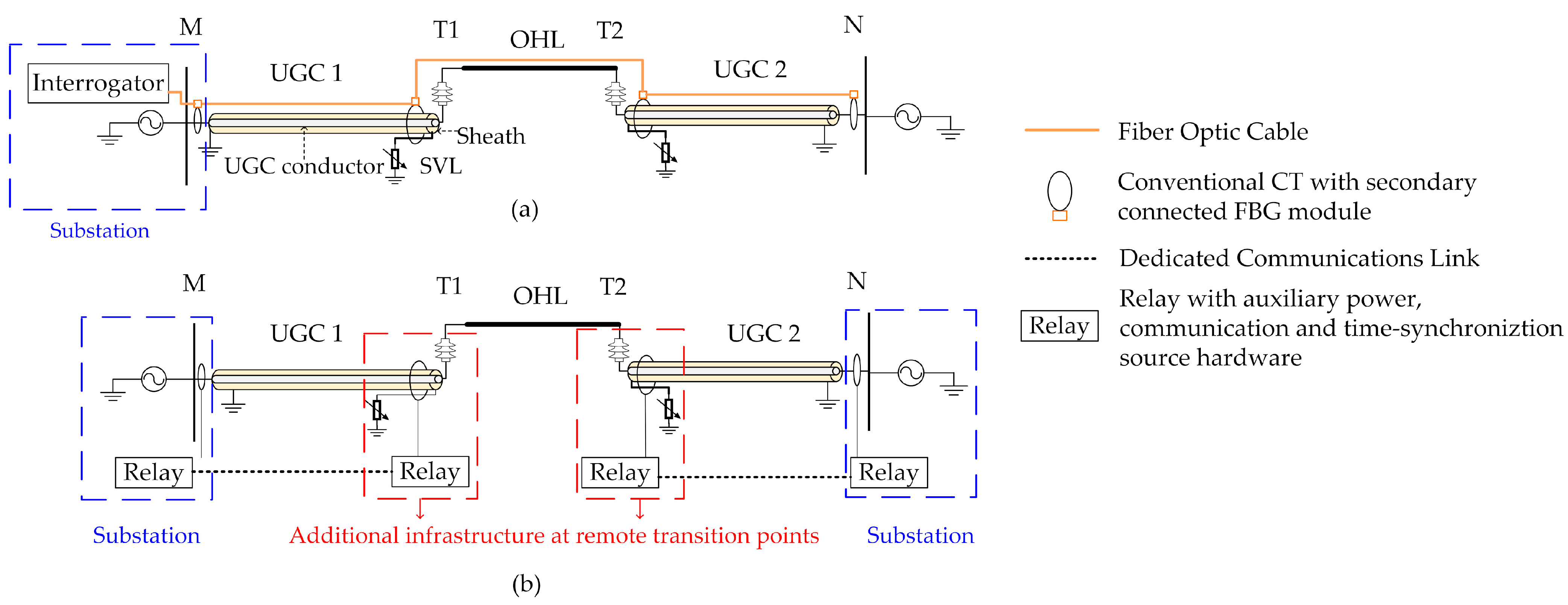
2.1. Distributed Sensing Platform

The distributed sensing platform utilized in this paper consists of conventional current transformers (CTs) with secondary connected FBG modules, connected via a single FO cable which is terminated at a single interrogator unit deployed in the substation. Multiple FBG modules (up to 60) can be connected to a single interrogator, thereby allowing one single interrogator to monitor multiple cable sections. The FBG modules do not require auxiliary power supplies, may be connected to existing CTs (if available), and are interfaced via existing FO cables available in high-voltage (HV) circuits. In contrast, Figure 1b illustrates the hardware requirements for a traditional differential protection scheme, which requires relays at each cable terminal, including at the transition points. Such an approach requires multiple relays, auxiliary power supplies, and dedicated communication infrastructure at (possibly remote) transition points, thus presenting significantly higher costs and complexity levels compared with the proposed scheme, based on the distributed sensing platform, presented in this paper.
The interrogator unit contains a light source that is transmitted via the FO cable. The FBG modules transduce the current measurements into Bragg grating wavelengths which are detected at the interrogator and converted into time-synchronized current measurement samples in real time. Further details on this process can be found in [12]. The interrogator unit can host monitoring and protection algorithms including standard phasor extraction methods, for example, discrete Fourier transform (DFT) [13], as well as the proposed selective AR scheme. It should be noted that the FBG sensors, interrogator processing algorithms, and data filtering and pre-processing are not modelled in this paper. Applying the distributed sensing platform to mixed circuits, two-ended CT measurements from n multiple cable sections are transduced using FBG sensors (two per UGC section, resulting in 2n sets of three-phase sensors), and transmitted via a single FO cable to an interrogator unit in the substation, as illustrated in Figure 1. In this paper, the distributed sensing platform is assumed to be installed in conjunction with the existing primary protection, for example, conventional differential protection using measurements from the terminals of the mixed circuit (but not the transition points). Distributed sensing, therefore, allows for economic monitoring of the transition points, which is used as inputs for the proposed selective AR scheme. However, the distributed sensing platform and proposed scheme can be utilized for primary protection if desired.

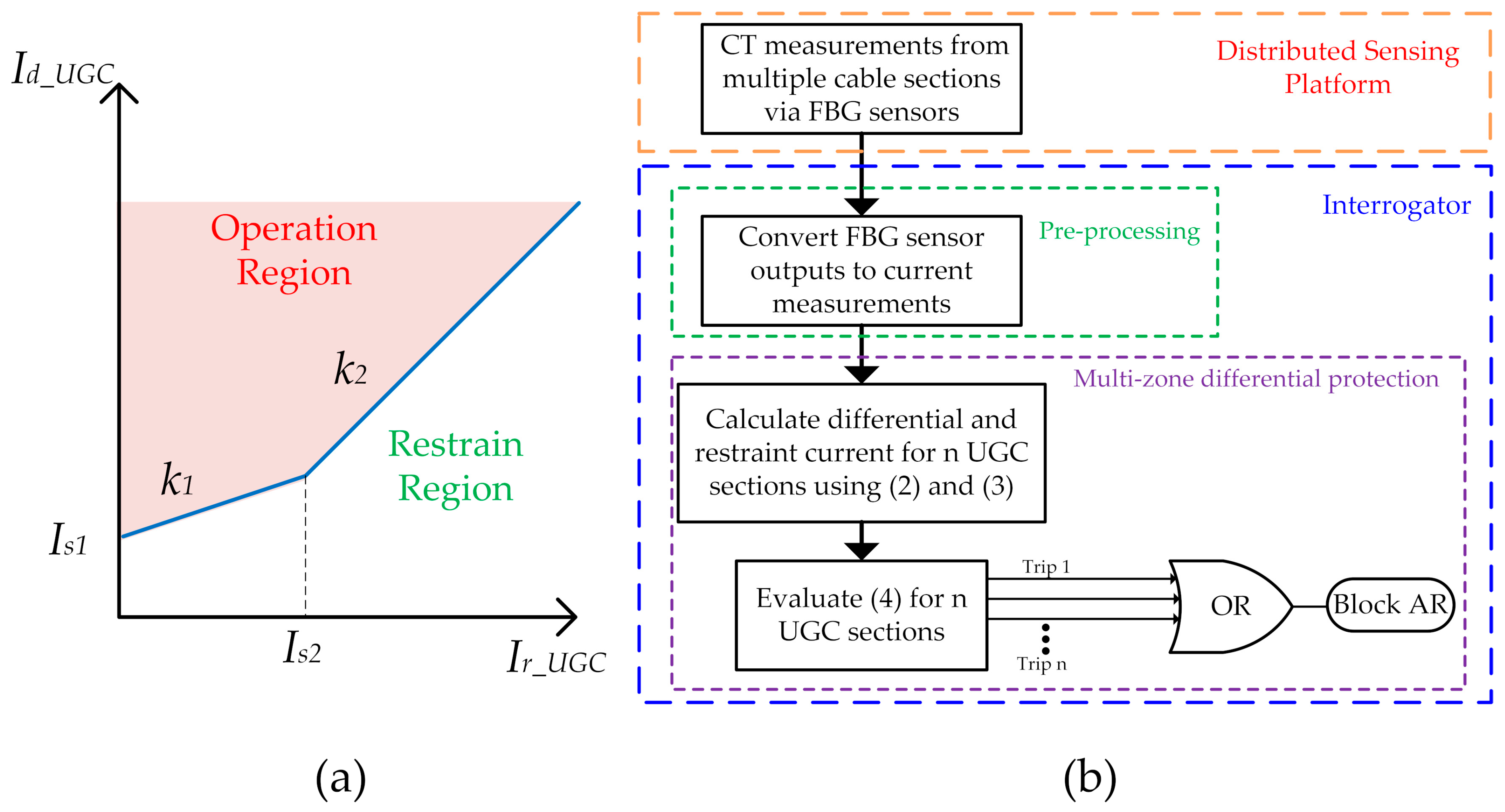
2.2. Multi-Zone Differential Protection Scheme

This section will present the principle of the proposed selective AR scheme using a multi-zone differential protection operation with an example mixed circuit, shown in Figure 1, which contains two UGC sections and an OHL section. Each cable section comprises a cable conductor and a metal sheath that provides physical protection for the cable as well as a return path for fault current. Under normal operating conditions, current flowing through the cable will induce a voltage in the cable sheath. If the cable sheath was grounded at both ends, this voltage would drive a sheath current, leading to heating losses in the cable. To prevent this, cable bonding techniques are used to bond and earth cable sheaths while eliminating or reducing sheath currents. A typical configuration, named single-point bonding, is shown in Figure 1. In this bonding method, one end of the sheath is grounded at the substation and the other end is connected to earth via a sheath voltage limiter (SVL). The SVL is a surge arrestor that protects the cable’s outer insulation from overvoltage during transient conditions. The cable section is monitored via conventional CTs installed around the insulated cable. Solid core or split core CTs can be used. The CT secondary outputs are interfaced with FBG-based sensors that are multiplexed via a standard single-mode FO cable. At the transition points T1 and T2, the cable (including the sheath) is routed on a riser pole, transmission tower, or other supporting structure. The cable conductor is connected to the OHL via a cable bushing, and the sheath earth conductor is routed to an earth connection. Before being earthed, the sheath must also be passed through the CT installed around the underground cable, as shown in Figure 1 and described in [14] (i.e., the sheath is passed back through the CT to cancel out the current the sheath carries). Such a configuration reduces the insulation requirements for the CT (because the HV cable is already insulated) and is generally safer (in case of CT internal failure) compared to instrumenting the HV OHL directly. This configuration also does not require additional space at the transition point, as it is directly installed around the underground cable [14]. Monitoring of mixed circuit transition points using the described CT configuration incorporated into a distributed sensing platform also eliminates power requirements at remote locations and enables simple and well-understood protection principles to be applied. Therefore, the effective CT measurement, IT, at the transition point, T, is:
I   T = I C C   + I S H     I S H E  
where I C C , is the current flowing through the cable conductor, I S H is the current circulating through the cable sheath, and I S H E is the current flowing to earth via the sheath SVL. I S H E   effectively cancels out the sheath current from the CT measurement. This is important because the cable sheath may provide a path for earth fault current, thus impacting the selectivity of a differential protection for external faults to earth. It also enables the scheme to provide protection for faults on the cable bushing, as discussed further in Section 3.3. A typical current differential protection scheme using a two-slope characteristic [15], as illustrated in Figure 2a, is implemented for each phase, using a single UGC section using (2)–(4):
I d U G C = | I M + I T |  
I r U G C = | I M | + | I T | 2
where the tripping conditions is provided as:
{ I d U G C > k 1 I r U G C + I s 1 , if   I r U G C I s 2   I d U G C > k 2 I r U G C + ( k 1 k 2 ) I s 2 + I s 1 , if   I r U G C > I s 2  
where I M is the cable termination end current; I T is the effective cable transition end current measured by the CT at the transition point; I d U G C is the differential current; I r U G C is a restraining current; I s 1 is the relay minimum pick-up current; I s 2 represents the point at which the relay slope switches; and k 1 and k 2 are the relay bias slopes. Such a two-slope biased characteristic is commonly adopted and increases the stability and selectivity of the differential protection under various conditions, e.g., under large external fault currents [15]. Internal cable faults will result in current flowing from both ends of the cable towards the fault, leading to high differential current and low restraint current. External faults or non-fault conditions will result in similar current flowing through both CTs, resulting in low differential current and high restraining current. Equation (4) can therefore be used to determine whether a fault is internal or external to the cable section allowing AR to be blocked for internal cable faults. Current phasors from n multiple cable sections monitored by the distributed sensing platform can then be incorporated into a multi-zone differential protection scheme, hosted within the interrogator unit, to facilitate selective AR. Terminal measurements from each monitored UGC section are input to (2)–(4). Equation (4) describes the criteria to determine if the fault is located on a UGC section. All UGC sections are monitored and a fault on any UGC section will trigger the block AR decision. The proposed scheme, therefore, defines an independent differential current protection zone for each UGC section, using the enhanced monitoring capability of the distributed sensing platform, and uses simple relaying logic to achieve selective AR of mixed circuits, as summarized in Figure 2b.

3. Case Studies

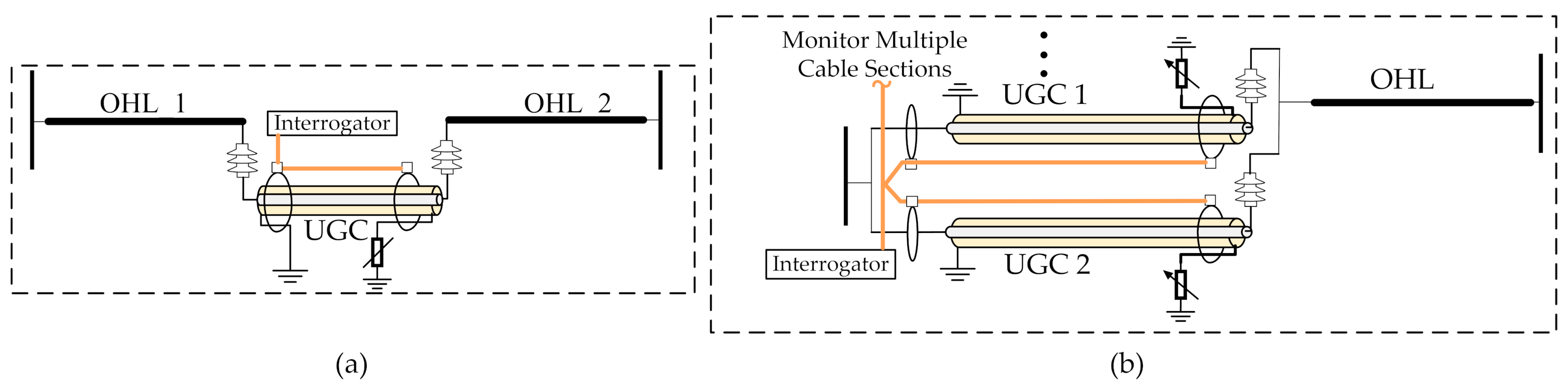
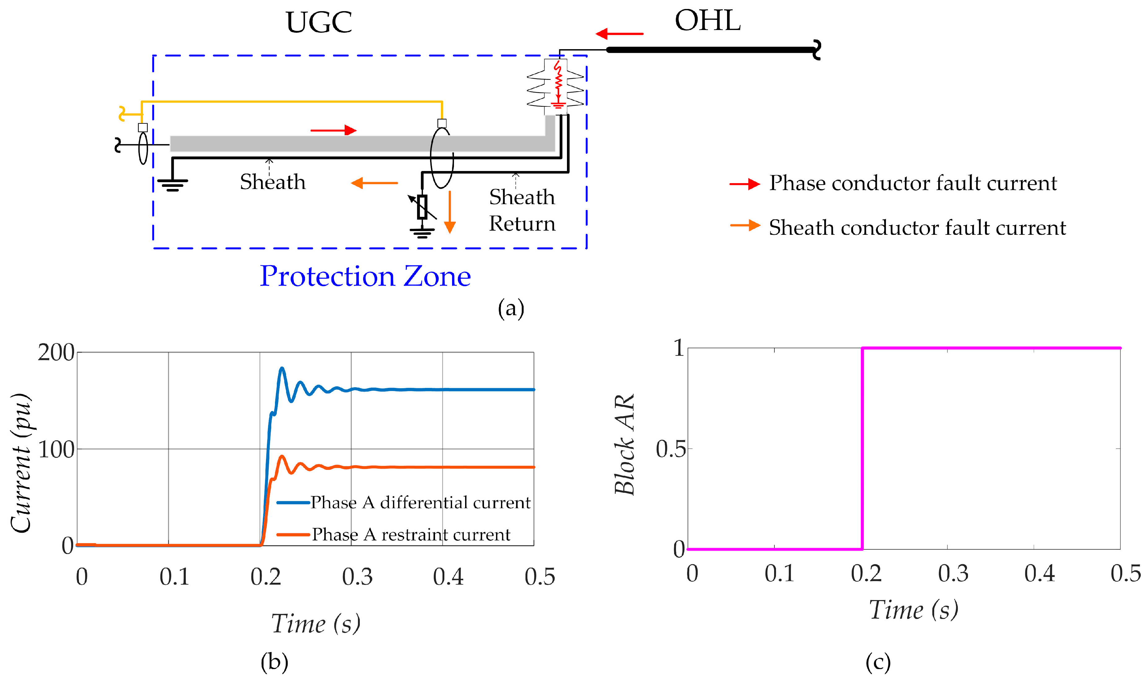
3.1. Single UGC–OHL Mixed Conductor Circuits

The mixed conductor circuit consisting of a single UGC and OHL section was modelled and simulated in the MATLAB/Simscape environment. The associated parameters of the test system are presented in Table 1. Typical cable parameters for a cross-linked polyethylene (XLPE) cable with an aluminum polyethylene-laminated (APL) sheath, available from [16], and overhead transmission line parameters, available from [17], were used. The cable arrangement was assumed to be flat and the rated withstand voltage of the cable sheath was assumed to be approximately 31 kV for a 132 kV-rated cable [18]. The protection voltage of the SVL was, therefore, set to a value below this threshold, as the withstand rating may degrade with time [18]. For this case, the UGC length was set at 1 km and the OHL section was set at 10 km, representing a typical scenario of a UGC section being used to connect an OHL circuit to a substation due to physical space or environmental constraints. Faults were simulated on the OHL section and on the UGC section. The cable CT measurements were input into Equations (2)–(4) to determine the faulty zone and block AR for internal cable faults. Figure 3 illustrates the performance of the proposed scheme for a mixed conductor circuit consisting of a single UGC and OHL section. Figure 3a illustrates the calculated differential and restraining quantities, as calculated by Equations (2)–(4), respectively, present in the UGC section for the faulty phase of a conductor to earth external fault on the OHL. It is observed that the restraining quantity exceeds the differential current. Based on Equation (4), the AR is not blocked, as shown by the logical 0 value of the Block AR output illustrated in Figure 3b. Figure 3c illustrates the calculated differential and restraining currents present in the UGC section for the faulty phase of a conductor-to-sheath-to-earth internal fault on the UGC section. It is observed that the differential current exceeds the restraining current. This satisfies the condition defined in Equation (4), and the AR is blocked as shown by the logical value 1 of the Block AR output illustrated in Figure 3d.

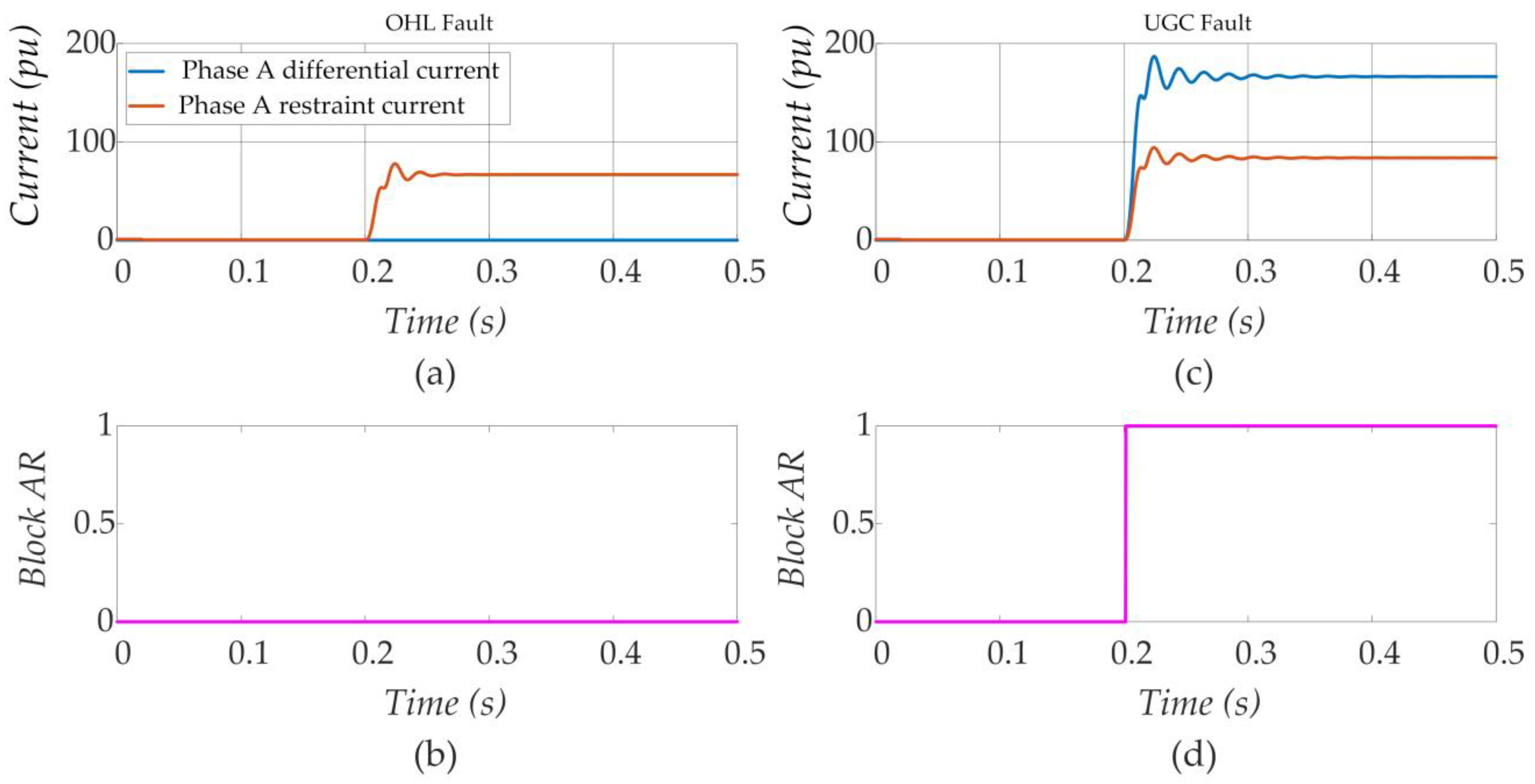
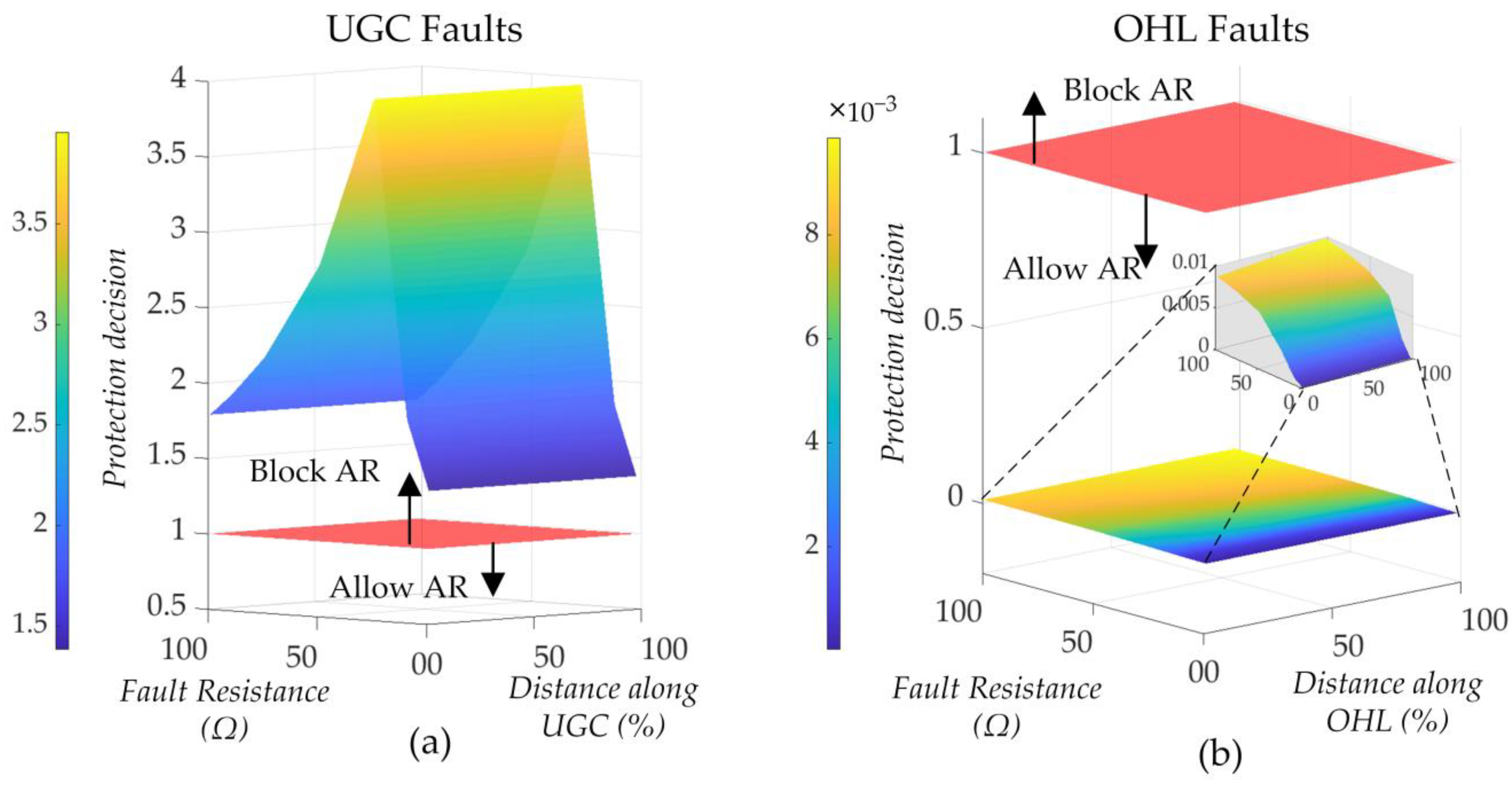
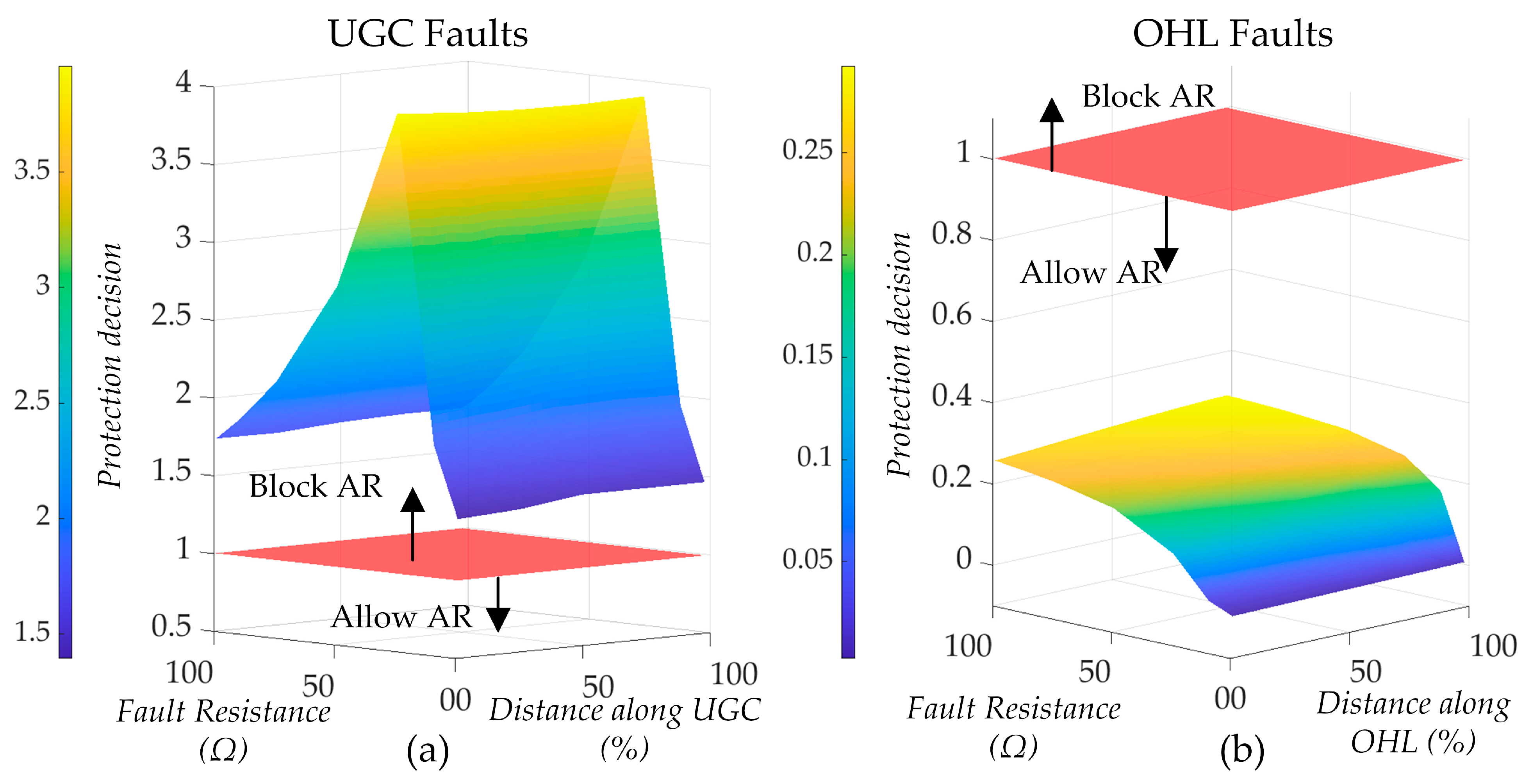
3.1.1. Impact of Fault Resistance and Fault Location

To assess the performance of the proposed scheme for various fault conditions, faults of varying fault resistances were simulated at different locations along the UGC and OHL sections. The UGC terminal end currents were provided to the differential protection scheme, as described by Equations (2)–(4), to determine the faulty zone and, therefore, achieve selective AR. For ease of illustration, Equation (4) can be expressed as:
I d U G C K I r U G C > 1  
where K I r U G C represents the appropriate restraint characteristic described by the expressions in Equation (4). The ratio of the differential and restraint quantities described in Equation (5) (i.e., the multi-zone differential protection decision) was plotted for different fault resistances and locations along both the UGC and the OHL. The selective AR decision boundary is a plane corresponding to the value of 1 on the z-axis. If the ratio is above this threshold, the fault is internal to the UGC section, so the trip condition for that particular UGC section and, consequently, the Block AR signal, will be activated. On the contrary, if the ratio is below this threshold, the fault is external to the UGC and AR can be enabled; therefore, the Block AR signal is inactive. Figure 4a shows the results for the faulty phase of a conductor-to-sheath-to earth fault on the UGC section. The fault locations along the UCG are illustrated relative to the substation terminal. The results indicate that for all fault resistances and locations along the UGC section, the fault was identified as internal to the UGC section and AR was blocked. Figure 4b shows the results for the faulty phase of a conductor-to-earth fault on the OHL section. The fault location along the OHL is defined relative to the UGC–OHL transition point. The results indicate that for all fault resistances and locations along the OHL section, the fault was identified as external to the UGC section and AR was not blocked. The faulty zone was correctly identified, with the selective AR achieved even for fault locations near the UGC–OHL transition (distance along UGC > 90% and distance along OHL < 10%). This demonstrates that the proposed scheme can provide selective and dependable performance near UGC–OHL transition points, which is challenging to achieve with conventional methods.

3.1.2. Impact of SVL

The SVL protects the sheath sectionalizing insulators and cable jackets from transient overvoltage associated with lightning, switching transients, and faults. Metal oxide varistors (MOVs) are widely adopted as SVLs due to their fast transient response and compact design. The current flowing in the metal sheath can be influenced by the nonlinear resistance characteristic of the MOV-based SVL. The MOV exhibits a large resistance and, hence, permits only very limited current conduction for voltages below the protection voltage. When the voltage is above this threshold, there is a rapid decrease in resistance and, hence, a large increase in current conduction with the increase in applied voltage [19]. The SVL is typically not designed to mitigate overvoltage resulting from external system faults or internal cable faults [18]. However, to ensure the performance of the proposed method in the case of SVL conduction, a typical MOV characteristic was incorporated into the simulation. Under transient conditions, for example, a large fault current flowing in the cable conductor induces a large transient overvoltage, triggering the SVL. This will result in a non-sinusoidal current flowing within the cable sheath because of the nonlinear varying resistance of the MOV. Due to the CT installation method adopted in the proposed scheme, the sheath’s return to earth is passed back through the CT to cancel out the current the sheath carries, resulting in an effective CT measurement, as described by Equation (1) [14]. This effectively eliminates the impact of the SVL and will not compromise the detection of the faulty section. It should be noted that if the CT is installed only around the outer cable jacket (including the sheath and cable conductor), without the sheath return routed through the CT, the sheath current influenced by the SVL can impact the performance of the proposed scheme. Figure 5a compares the cable terminal CT currents for an external fault near the transition point with SVL conduction using the adopted CT method, with the sheath return routed through the CT and the CT installed on only the outer cable jacket. It can be observed that when the sheath current is not routed through the CT at the transition point, the measured current is influenced by the SVL, leading to a distorted waveform. Figure 5b shows that under such conditions, an external fault can be identified as an internal fault within the protected zone, leading to an incorrect AR block signal. This highlights the importance of the CT installation method in the proposed scheme. In contrast, the adopted CT installation effectively mitigates the impact of SVL sheath current leading to a correct Block AR inactive signal. Similarly, under internal fault conditions, the proposed method can operate effectively, regardless of the SVL conduction, with negligible impact on performance compared to results presented in previous sections.

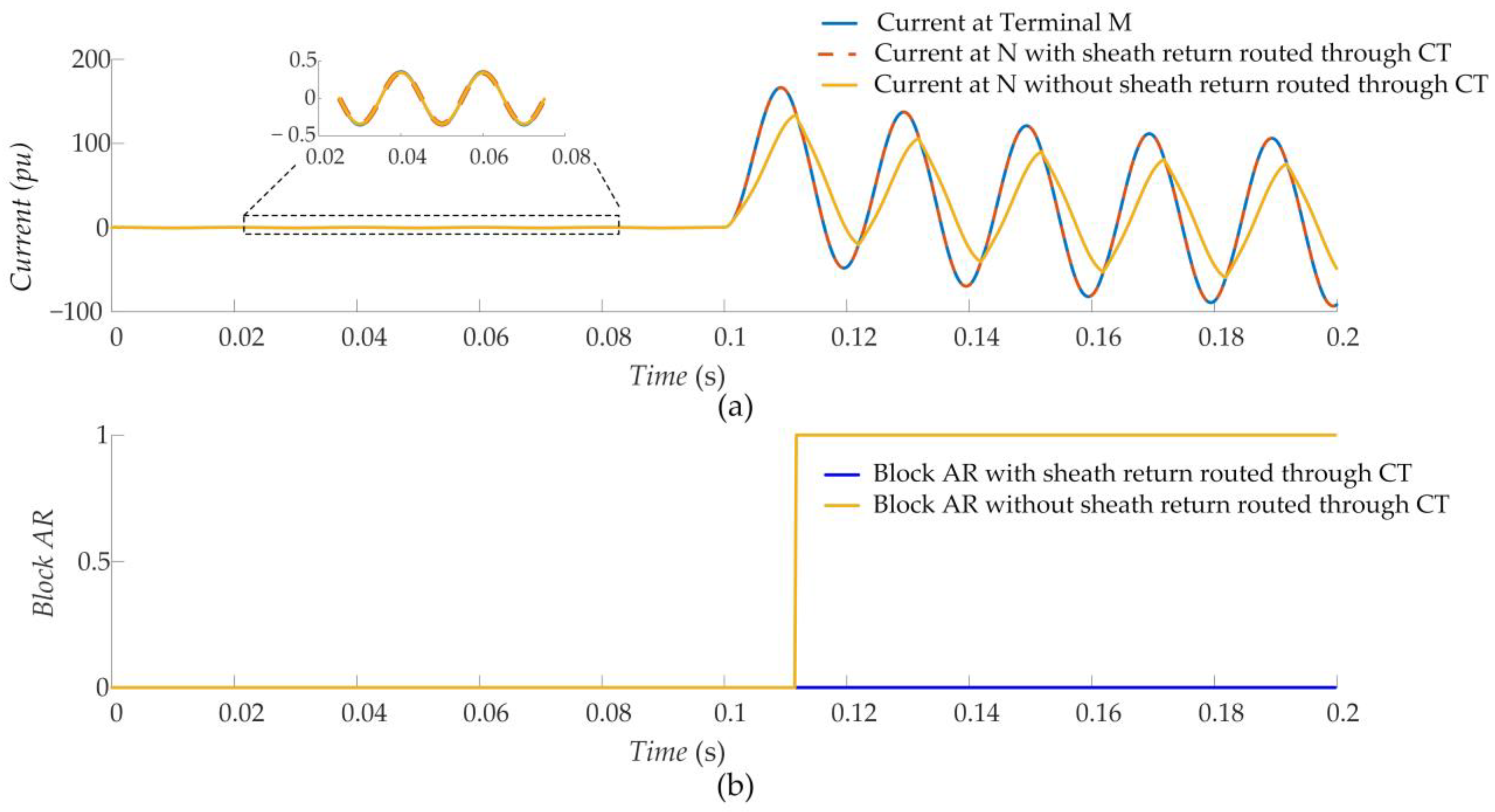
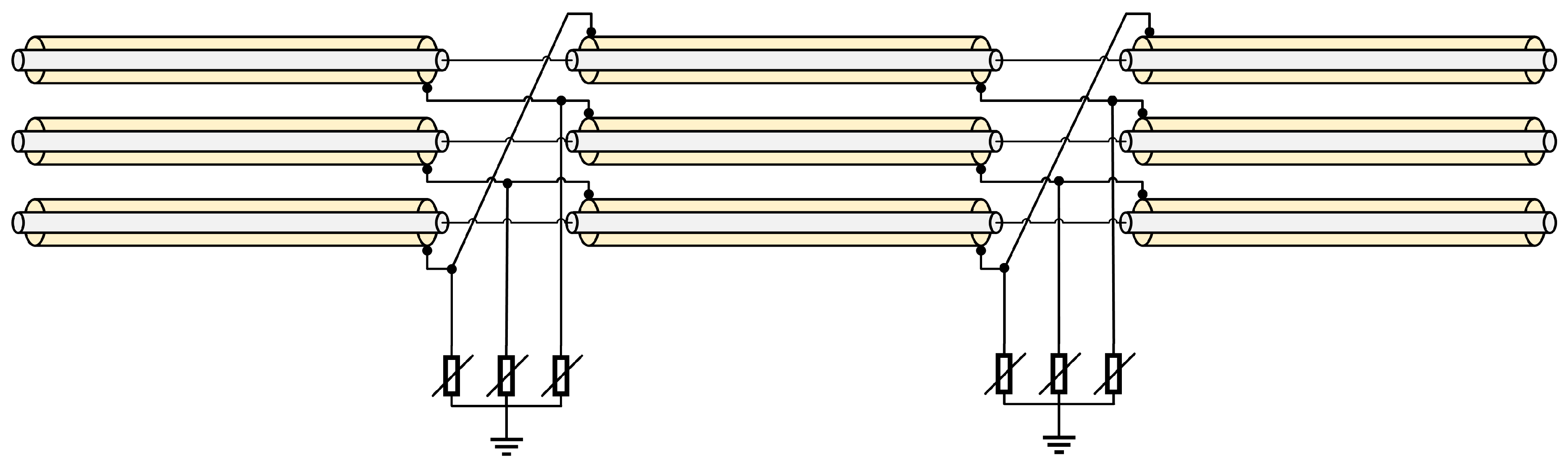
3.1.3. Impact of Bonding Technique

AC current flowing through a cable conductor can induce voltages in metal sheaths. If the metal sheaths are earthed at both ends forming a closed circuit, then induced voltage will drive a circulating sheath current, leading to heating losses and a reduction in the cable current rating. Therefore, other approaches to cable sheath bonding are widely adopted to reduce induced sheath currents, thus reducing sheath current losses in the cable. As described previously, single-point bonding connects one end of the cable sheath directly to earth, with the other end connected via an SVL, which provides protection against transient overvoltages. However, this method is usually adopted for short cable lengths. Sectionalized cross bonding, as illustrated in Figure 6, is typically adopted for high-voltage cables, especially with a long cable section. The cable sheath is interrupted at defined points and connections are made between sheaths of the successive phase. This effectively results in out-of-phase induced voltages being summed, thus greatly reducing the total induced voltage, which limits circulating sheath currents. SVLs are installed at the cross-bonding points to protect the sheath interconnections from overvoltages. The impedance variations introduced by sheath cross-bonding must be considered for distance-based protection methods, leading to increased complexity. To demonstrate the performance of the proposed scheme for UGC sections with sheath cross-bonding, a test system was created to include sectionalized cable sheath cross-bonding. The UGC section is 30 km in total, with sheath cross-bonding via an SVL applied at 10 km sections, as shown in Figure 6. Figure 7a shows the results for the faulty phase of a conductor-to-sheath-to-earth fault on the UGC section. The fault locations along the UCG are illustrated relative to the substation terminal. The results indicate that, for all fault locations, the fault was identified as internal to the UGC section and AR was blocked. Figure 7b shows the results for the faulty phase of a conductor-to-earth fault on the OHL section. The fault location along the OHL is defined relative to the UGC–OHL transition point. The results indicate that, for all fault locations, the fault was identified as external to the UGC section and AR was not blocked. The results illustrated in Figure 4 and Figure 7 indicate that the proposed differential protection scheme can achieve selective AR for different bonding techniques, without any changes to the protection algorithm.

3.2. Different Mixed Conductor Topologies

Varying physical and environmental constraints along transmission circuit routes can lead to several different mixed conductor circuit topologies. Figure 1 and Figure 8 illustrate three commonly found mixed circuit topologies, as reported in [2]. Figure 8 shows a two-ended circuit with multiple series connected UGC sections, Figure 8a shows a two-ended circuit with a UGC section in between two OHL sections, commonly referred to as a siphon circuit, and Figure 8b shows a two-ended circuit with multiple, parallel UGC sections. To assess the performance of the proposed mixed circuit protection scheme for a wide range of mixed circuit topologies, the three scenarios described were modelled. One-kilometer cable sections with single-point bonding and 10 km OHL sections was modelled, and faults with a resistance of 100 ohm were simulated at the mid-point of each UGC cable section and OHL section. The cable terminal currents, as would be measured by a passive distributed sensing system, are provided to the protection scheme described by Equations (2)–(4). Table 2 illustrates the results of the proposed scheme for the different mixed circuit topologies and different fault types. Based on the physical structure of cables, it is expected that the faulty loop will typically include the conductor-to-sheath-to-earth path. Such faults are, therefore, the focus of this paper. The results show that selective AR was achieved, with AR blocked for internal UGC section faults and not blocked for external OHL faults, for all mixed circuit topologies and faults simulated. Similar results were obtained for circuits consisting of multiple series connected UGC and OHL sections, representative of transmission routes that are subject to physical and environmental constraints. This demonstrates the adaptability of the proposed multi-zone differential protection scheme for all mixed circuit topologies. A distributed sensing platform integrating multiple sensors via a single fiber cable reduces the complexity and cost of monitoring multiple cable sections. Depending on the installed CT locations, alterations to the proposed scheme can also be easily achieved and hosted on the interrogator. For example, selective AR has also been achieved by adopting three- or four-ended differential protection zones for parallel UGC sections. Due to space constraints, these results are not presented in this paper. The enhanced monitoring capability of the distributed sensing platform combined with the high selectivity of the proposed multi-zone differential scheme can offer cost-effective, selective AR of mixed conductor circuit topologies.

3.3. Faults on Insulator/Cable Sealing End at Transition Points

Conventionally, the protected zone of a differential protection scheme is bounded by the location of the CTs. However, the protected zone of the proposed scheme is influenced by the earthing arrangements and the CT installation method at the UGC–OHL transition point. As described previously, the cable and sheath conductor are terminated via a cable bushing on a riser pole or structure at the transition point. The sheath return is then routed through the CT and earthed via the SVL. Consider an earth fault occurring on the cable bushing. Fault current flows through the phase conductors from both the UCG and OHL sections to the fault point, and the sheath and sheath return provide paths for the current to flow to earth. The faulty loop current flowing in the cable sheath and sheath return is influenced by the operating point (i.e., impedance) of the SVL and results in current flowing into the protected zone via the sheath, due to the CT configuration, as shown in Figure 9a. The SVL is not typically designed to conduct during cable faults or earth faults in the power system [18]. A cable bushing fault is simulated, as shown in Figure 9a, using the test system and parameters described in Section 3.1. Figure 9b shows the differential and restraint currents observed by the protection CTs. Figure 9c illustrates that the proposed scheme detected the fault on the cable bushing, confirming that the protection zone includes the cable bushing at the transition point. It should also be noted that OHL faults that result in insulation flashover at the cable sealing end will, therefore, result in fault current flowing into the protected zone via the cable sheath, resulting in blocked AR. This can be beneficial, as a cable sheath which has been subjected to high fault currents, along with the cable terminations, bushings, or surrounding equipment, may be damaged by such a fault.

4. Discussion

The results presented in Section 3 illustrate the effectiveness of the proposed multi-zone differential scheme to correctly identify the faulty zone of mixed OHL–UGC circuits under a variety of circuit topologies and fault conditions. This demonstrates that the proposed method can achieve selective AR of such complex circuits. Table 3 highlights the benefits and limitations of several commonly applied or proposed mixed OHL–UGC circuit protection methods and compares them to the proposed scheme presented in this paper. It is evident that the proposed multi-zone differential protection scheme, enabled by passive distributed sensing, addresses all the limitations of other commonly applied or proposed methods described in the literature. The proposed scheme can successfully discriminate between UGC and OHL section faults near UGC–OHL transitions as well as for different mixed circuit topologies and bonding arrangements. This provides improved performance over distance protection and travelling wave methods. The passive distributed sensing platform consisting of CTs and FO sensors multiplexed via a single FO cable (over a distance of up to 60 km from the nearest substation) eliminates the need for additional equipment and auxiliary power supplies at UGC–OHL transitions, as required by traditional differential current protection methods. The need for dedicated communication networks, as required by traditional differential current protection methods, is also eliminated. The communication latency of the optical sensing platform is relatively small and predictable compared to conventional hard-wired communication links and can be accounted for in the interrogator preprocessing [20,21]. This mitigates against communication latency and ensures accurate time synchronization of measurements. The CTs with secondary connected FBG modules described in this paper have been certified, to an accuracy of 5% or higher, to a standard limiting factor for protection applications, as described in IEC 61869 [22]. The improved monitoring capability of the distributed sensing platform using FBG sensors also offers clear advantages over optical CTs, which require dedicated FO cables per UGC section and are suitable only for relatively short cable sections due to limitations on FO cable length. Distributed sensing, therefore, allows for easier and more cost-effective monitoring of a wider range of mixed UGC–OHL topologies (including multiple cable sections and bonding configurations) in comparison to conventional protection approaches or optical CTs. The approach is commercially available for industry applications in HV circuits [23]. Additionally, the proposed distributed sensing-enabled multi-zone differential protection scheme can be utilized as a primary protection method.

5. Conclusions and Future Work

Mixed UGC–OHL circuits are becoming more prevalent due to increasing demand in dense urban areas and the associated environmental and physical space constraints along power transmission and distribution routes. Selective AR of such circuits is important to maintain power system reliability and security by reconnecting circuits after temporary OHL faults. However, AR of mixed UGC–OHL circuits for UGC section faults can result in permanent damage and should be blocked. To achieve this, a selective AR based on the multi-zone differential protection principle using a passive distributed sensing platform has been proposed. The proposed method provides CT measurements at UGC section terminals to a two-slope multi-zone differential protection scheme. The proposed method has been applied to a comprehensive range of practical mixed OHL–UGC topologies and fault scenarios through simulations conducted in the MATLAB/Simscape environment. The results demonstrate the effectiveness of the proposed scheme in achieving selective AR of mixed UGC–OHL for various fault conditions, UGC sheath bonding methods, and mixed circuit topologies. The proposed method, therefore, provides a dependable, secure, and highly selective AR method for mixed UGC–OHL circuits, thus providing a promising solution for enhancing power system reliability and security in the presence of such circuits. Although the simulation results presented in this paper do not model the distributed sensing platform, the impacts of CT saturation, and other potential hardware related issues, these are well understood and can be resolved through proper power system protection practices. It can also be noted that the solution is immune to factors such as communications delays and data loss. The impact of measurement errors has not been assessed in this paper, but are expected to have negligible impact of the proposed differential protection scheme, as the distributed sensing platform is compliant with widely adopted protection class measurement accuracy standards (IEC 61869) [22].
The proliferation of converter-interfaced renewable energy sources (RESs) and the need to connect such RESs while meeting environmental and physical space constraints will lead to an increase in mixed UGC–OHL circuits interfacing RESs to power networks with reduced fault levels. The converter-modulated fault characteristics of RESs have been shown to impact the dependability of transmission lines’ differential current protection under such conditions [24]. Therefore, the impact of the proposed scheme under different fault characteristics and weak system conditions associated with a high penetration of RESs should also be investigated. Distributed sensing also allows for high-resolution synchronized waveform measurements of UGC section currents and voltages. Such measurements can enable novel monitoring and protection functions using data analytic approaches. Temperature and strain sensors can also be integrated into the distributed sensing platform. These measurements can be correlated with electrical parameters to provide improved health monitoring of cables, terminations, and joints. The application of high-resolution, time-synchronized measurements available from a distributed sensing platform to the monitoring, protection, and control of mixed UGC–OHL circuits under power network conditions with a high penetration of RESs, therefore, represents a promising avenue for further research.

Author Contributions

Conceptualization, S.B.; methodology, S.B. and K.K.; software, S.B. and K.K.; validation, S.B. and Q.H.; formal analysis, K.K.; investigation, K.K.; resources, S.B.; data curation, K.K.; writing—original draft preparation, K.K.; writing—review and editing, S.B., Q.H. and P.N.P.; visualization, K.K.; supervision, Q.H., P.N.P. and S.B.; funding acquisition, S.B. and Q.H. All authors have read and agreed to the published version of the manuscript.

Funding

This research was funded by CENSIS and Synaptec, Glasgow, UK. The research is jointly funded by RESCUE (EP/T021829/1), https://gow.epsrc.ukri.org/NGBOViewGrant.aspx?GrantRef=EP/T021829/1 (accessed on 15 December 2022). P. N. Papadopoulos is supported by a UKRI Future Leaders Fellowship [MR/S034420/1]. All results can be fully reproduced using the methods and data described in this paper and references provided.

Data Availability Statement

Not applicable.

Conflicts of Interest

The authors declare no conflict of interest.

Nomenclature

ARAuto-reclose
FBGFiber Bragg grating
MOVMetal oxide varistor
OHLOverhead transmission line
RESRenewable energy source
SVLSheath voltage limiter
UGCUnderground cable

References

  1. IEEE Std C37.104-2022 (Revision of IEEE Std C37.104-2012); IEEE Guide for Automatic Reclosing on AC Distribution and Transmission Lines. IEEE: New York, NY, USA, 2022; pp. 1–82. [CrossRef]
  2. CIGRÉ. Short Circuit Protection of Circuits with Mixed Conductor Technologies in Transmission Networks; Conseil International des Grands Réseaux Électriques, Ed.; CIGRÉ: Paris, France, 2014; ISBN 978-2-85873-283-8. [Google Scholar]
  3. Bak, C.L.; Jensen, C.F. Distance Protection of Cross-Bonded Transmission Cable-Systems. In Proceedings of the 12th IET International Conference on Developments in Power System Protection (DPSP 2014), Copenhagen, Denmark, 31 March–3 April 2014; pp. 1–6. [Google Scholar]
  4. Xun, L.; Shungui, L.; Ronghui, H.; Jingwen, A.; Yunzhu, A.; Ping, C.; Zhengxiang, X. Study on Accuracy Traveling Wave Fault Location Method of Overhead Line—Cable Hybrid Line and Its Influencing Factors. In Proceedings of the 2017 Chinese Automation Congress (CAC), Jinan, China, 20–22 October 2017; pp. 4593–4597. [Google Scholar]
  5. He, L.; Wang, Z.; Liu, H.; Chen, T. A Double Terminal Traveling Wave Ranging Method of Overhead Line—Submarine Cable Hybrid Line. In Proceedings of the IECON 2017—43rd Annual Conference of the IEEE Industrial Electronics Society, Beijing, China, 29 October 2017; pp. 16–20. [Google Scholar]
  6. Naidu, O.D.; Pradhan, A.K.; Krishnamurthy, P. Traveling Wave Based Adaptive Auto-Reclosing and Fault Location for Three-Terminal Mixed Lines. In Proceedings of the 2019 IEEE PES GTD Grand International Conference and Exposition Asia (GTD Asia), Bangkok, Thailand, 21–23 March 2019; pp. 466–471. [Google Scholar]
  7. Kulikov, A.; Loskutov, A.; Pelevin, P. The Method of Faulted Section Estimation for Combined Overhead and Cable Power Lines Using Double-Ended Measurements. In Proceedings of the 2020 International Ural Conference on Electrical Power Engineering (UralCon), Chelyabinsk, Russia, 22–24 September 2020; pp. 70–75. [Google Scholar]
  8. Naidu, O.; Yalla, P.; George, N. Auto-Reclosing Protection Scheme for Multi-Terminal Mixed Lines Using Synchrophasor Measurements. In Proceedings of the 2019 International Conference on Smart Grid Synchronized Measurements and Analytics (SGSMA), College Station, TX, USA, 21–23 May 2019; pp. 1–6. [Google Scholar]
  9. Klomjit, J.; Ngaopitakkul, A. Comparison of Artificial Intelligence Methods for Fault Classification of the 115-KV Hybrid Transmission System. Appl. Sci. 2020, 10, 3967. [Google Scholar] [CrossRef]
  10. Arifin, Z.; Zulham, M.; Prasetyo, E. Impact of Optical Current Transformer on Protection Scheme of Hybrid Transmission Line. IJEECS 2021, 24, 1. [Google Scholar] [CrossRef]
  11. Orr, P.; Booth, C.; Fusiek, G.; Niewczas, P.; Dysko, A.; Kawano, F.; Beaumont, P. Distributed Photonic Instrumentation for Smart Grids. In Proceedings of the 2013 IEEE International Workshop on Applied Measurements for Power Systems (AMPS), Aachen, Germany, 25–27 September 2013; pp. 63–67. [Google Scholar]
  12. Orr, P.; Niewczas, P. High-Speed, Solid State, Interferometric Interrogator and Multiplexer for Fiber Bragg Grating Sensors. J. Lightwave Technol. JLT 2011, 29, 3387–3392. [Google Scholar] [CrossRef]
  13. Muscas, C.; Pegoraro, P.A. Chapter 3—Algorithms for Synchrophasors, Frequency, and ROCOF. In Phasor Measurement Units and Wide Area Monitoring Systems; Monti, A., Muscas, C., Ponci, F., Eds.; Academic Press: Cambridge, MA, USA, 2016; pp. 21–51. ISBN 978-0-12-804569-5. [Google Scholar]
  14. CIGRÉ. Transition Requirements—Input Sources for the Relays at the Transition. In Short Circuit Protection of Circuits with Mixed Conductor Technologies in Transmission Networks; Conseil International des Grands Réseaux Électriques, Ed.; CIGRÉ: Paris, France, 2014; pp. 199–200. ISBN 978-2-85873-283-8. [Google Scholar]
  15. Tziouvaras, D.A.; Altuve, H.; Benmouyal, G.; Roberts, J. Line Differential Protection with an Enhanced Characteristic. In Proceedings of the Eighth IEEE International Conference on Developments in Power System Protection, Amsterdam, The Netherlands, 5 April 2004; p. 9. [Google Scholar]
  16. NKT Cables XLPE Al Single Core 76/132 KV. Available online: https://www.nkt.com/products-solutions/medium-voltage/medium-voltage-cables/xlpe-al-single-core-76-132-kv (accessed on 22 April 2022).
  17. TransPowr® ACSR Bare Overhead Conductor (US)—Utilities & Power Grids North America. Available online: https://na.prysmiangroup.com/product-center (accessed on 26 April 2022).
  18. Hitachi ABB Power Grids. Application Note 3.1—Cable Sheath Overvoltage Protection; Application Guidelines Overvoltage Protection, Metal Oxide Surge Arrestors in Medium-Voltage Systems; Hitachi ABB: Zurich, Switzerland, 2020. [Google Scholar]
  19. IEEE. IEEE Guide for Bonding Shields and Sheaths of Single-Conductor Power Cables Rated 5 KV through 500 KV; IEEE: New York, NY, USA, 2014. [Google Scholar]
  20. Orr, P.; Niewczas, P.; Dyśko, A.; Booth, C. FBG-Based Fibre-Optic Current Sensors for Power Systems Protection: Laboratory Evaluation. In Proceedings of the 2009 44th International Universities Power Engineering Conference (UPEC), Glasgow, UK, 1–4 September 2009; pp. 1–5. [Google Scholar]
  21. Orr, P.; Gordon, N.; Clayburn, L.; Ma, Z.; Hong, Q.; Tzelepis, D.; Hurzuk, N.S.; Løken, R.; Booth, C. Implementation of Centralised, Numerical Busbar Protection Using Distributed Photonic Current Sensors. In Proceedings of the PAC World Conference, Glasgow, UK, 15 April 2019. [Google Scholar]
  22. IEC 61869-1; Instrument Transformers: General Requirements; International Electrotechnical Commission. IEC: London, UK, 2007.
  23. Synaptec Mixed Circuit Protection. Available online: https://synapt.ec/mixed-circuit-protection-in-transmission-thank-you/ (accessed on 15 September 2022).
  24. Kawal, K.; Hong, Q.; Paladhi, S.; Liu, D.; Papadopoulos, P.N.; Blair, S.; Booth, C. Vulnerability Assessment of Line Current Differential Protection in Converter–Dominated Power Systems. In Proceedings of the 16th International Conference on Developments in Power System Protection (DPSP 2022), Newcastle, UK, 7–10 March 2022; Volume 2022, pp. 362–367. [Google Scholar]
Figure 1. Simple mixed conductor circuit consisting of UGC sections and an OHL section; (a) distributed sensing platform; (b) traditional differential protection requirements.
Energies 16 02558 g001
Figure 2. (a) Two-slope differential current characteristic; (b) selective AR procedure.
Energies 16 02558 g002
Figure 3. Performance of the multi-zone differential scheme; (a) OHL fault; (b) AR not blocked for OHL fault; (c) UGC fault; (d) AR blocked for UGC fault.
Energies 16 02558 g003
Figure 4. Performance of the proposed scheme for different fault conditions: (a) faults on the UGC section, (b) faults on the OHL section.
Energies 16 02558 g004
Figure 5. Performance of the proposed scheme with SVL conduction for an external fault and different CT arrangements, (a) UGC terminal currents, (b) selective AR performance.
Energies 16 02558 g005
Figure 6. UGC with sectionalized cable sheath cross-bonding.
Energies 16 02558 g006
Figure 7. Performance of the proposed scheme with UGC sheath cross-bonding; (a) faults on the UGC section, (b) faults on OHL sections.
Energies 16 02558 g007
Figure 8. Mixed conductor circuit topologies; (a) two-ended circuit with UGC section between two OHL sections, (b) two-ended circuit with multiple UGC sections.
Energies 16 02558 g008
Figure 9. Performance of the proposed scheme for cable bushing faults; (a) protection zone of the proposed scheme, (b) differential and restraint currents due to cable busing fault, (c) output of the proposed scheme.
Energies 16 02558 g009
Table 1. Test System Parameters.
ParameterDescriptionValue
VbaseSystem base voltage132 kV
fSystem frequency50 Hz
SbaseSystem base power100 MVA
SfaultSubstation fault level8 GVA
AradUGC conductor radius42.0 mm
BradUGC sheath radius98 mm
CradUGC outer radius108 mm
RUCGUGC conductor resistance per length0.0201 Ω/km
RSHUGC sheath resistance per length0.065 Ω/km
LUCGUGC conductor inductance per length0.55 mH/km
CUCGUGC capacitance per length0.304 µ F/km
RlineOHL resistance per length0.124 Ω/km
XlineOHL reactance per length0.192 Ω/km
CL-LOHL line-to-line capacitance per length0.301 µF/km
CL-GLine-to-ground capacitance per length0.1 µF/km
VSVLSheath voltage limiter protection voltage30 kV
k1Differential current relay bias slope 10.3
k 2Differential current relay bias slope 21.5
Is1Relay minimum pick-up current1.0 A secondary
Is2Slope 1, slope 2 transition point5.0 A secondary
Table 2. Performance of the proposed scheme for different mixed circuit topologies.
Mixed Circuit TopologyFault Scenario I d U G C I r U G C   Block AR (Y/N)
Fault LocationFault TypePhase APhase BPhase A
Two-ended circuit with multiple series connected UGC–OHL sectionsUGC_1A-Sh-E1.27250.04260.0379Y
A-B-Sh-E1.08031.4100.0437Y
A-B-C-Sh-E1.23121.23121.2312Y
OHLA-E0.01700.04250.0382N
A-B0.01620.01650.0396N
A-B-E0.01290.01750.0436N
A-B-C0.01590.01590.0159N
UGC_2A-Sh-E1.63920.04200.0435Y
A-B-Sh-E1.54421.63580.0437Y
A-B-C-Sh-E1.61231.61221.6122Y
Two-ended circuit with UGC section between OHL sections (siphon)OHL_1A-E0.01010.01260.0126N
A-B0.01030.01020.0127N
A-B-E0.01030.01020.0126N
A-B-C0.01000.01000.0100N
UGCA-Sh-E1.80090.01270.0126Y
A-B-Sh-E1.62221.61490.0128Y
A-B-C-Sh-E1.80131.80131.8013Y
OHL_2A-E0.01010.01260.0126N
A-B0.01000.01000.0126N
A-B-E0.01030.01020.0127N
A-B-C0.00990.00990.0099N
Two-ended circuit with parallel cable sectionsUGC_1A-Sh-E1.33320.00450.0046Y
A-B-Sh-E1.33311.33320.0458Y
A-B-C-Sh-E1.33311.33321.3332Y
UGC_2A-Sh-E1.33310.00450.0046Y
A-B-Sh-E1.33321.33320.0490Y
A-B-C-Sh-E1.33321.33321.3332Y
OHLA-E0.01360.04910.0421N
A-B0.01330.01350.0451N
A-B-E0.01320.01320.0455N
A-B-C0.01320.01320.0132N
Table 3. Comparison of the proposed scheme with other mixed conductor circuit protection methods.
MethodAdvantagesLimitations
Distance protection [2]
No additional equipment at transition point.
Does not require communications infrastructure
Does not provide 100% selectivity
Complex for multiple cable sections
Impacted by different UGC sheath bonding methods
Travelling wave [4]
No additional equipment at transition point
Does not provide 100% selectivity, particularly near transition point
Requires high sampling rates and high-bandwidth communications
Prone to communications link failure
Current differential protection with CTs and conventional relays [2]
Provides 100% selectivity
Requires IEDs, CTs, and auxiliary power supplies at each transition point
Requires high-bandwidth communications infrastructure and time synchronization of relay measurements
Prone to communications link failure
Current differential protection with optical CTs [10]
Provides 100% selectivity
No IED or auxiliary power supply required at transition points
Requires dedicated optical fiber cable for each cable section
Limitation on length of optical-fiber cable (<10 km)
Prone to fiber link failure (damaged fiber optic cable)
Current differential protection using distributed sensing (proposed scheme)
Provides 100% selectivity
No IED, auxiliary power supply, or active electronics required at transition point
Only requires installation of CTs and sensors at transition point; can also secondary-connect to existing CTs
Scales to multiple cable sections and parallel conductors; can be monitored easily by multiplexing sensors using a single FO cable
Interrogator unit performs mixed circuit protection and other functions onboard, minimizing the required substation footprint
Prone to fiber link failure (damaged fiber optic cable, although approaches with redundancy are possible)
Disclaimer/Publisher’s Note: The statements, opinions and data contained in all publications are solely those of the individual author(s) and contributor(s) and not of MDPI and/or the editor(s). MDPI and/or the editor(s) disclaim responsibility for any injury to people or property resulting from any ideas, methods, instructions or products referred to in the content.

