
Evaluation of the Influence of the Load Resistance on Power and Efficiency in the Square and Circular Periodic WPT Systems

Faculty of Electrical Engineering, Bialystok University of Technology, Wiejska 45D, 15-351 Bialystok, Poland
Energies 2023, 16(7), 2950; https://0-doi-org.brum.beds.ac.uk/10.3390/en16072950
Submission received: 20 February 2023
/
Revised: 22 March 2023
/
Accepted: 22 March 2023
/
Published: 23 March 2023
(This article belongs to the Special Issue Load Modelling of Power Systems II)
Abstract
:We are currently seeing an increasing number of devices that support wireless power transfer (WPT) technology. In order to avoid early prototyping and carry out a series of experimental analyses, it was possible to use numerical methods at the design stage to estimate the potential power transfer and efficiency of the system. The purpose of this study is to present a method of analysis for a periodic wireless power transfer system, using periodically arranged planar coils with field and circuit models. A three-dimensional numerical model of a multi-segment charging system with periodic boundary conditions was solved with the finite element method (FEM). An equivalent circuit model of the periodic WPT system was proposed, and the required lumped parameters were obtained using analytical formulas. Mathematical formulas were supplemented with the analysis of several geometric variants, taking into account different sizes of transmitting and receiving coils, as well as different numbers of turns. Both proposed methods of analysis allowed for the determination of load resistance values at which the variants of WPT systems considered in the research had maximum efficiency. The ranges of load resistance values in which the efficiency of the system exceeded 50% were indicated. The results obtained are very helpful in the proper selection of the load resistance, without the need for multiple tests and their resulting multiple measurements. The results also showed that the proposed circuit model was able to achieve similar accuracy as the numerical model, and the complexity of the model and analysis was significantly reduced. The obtained results will allow the design of WPT systems with appropriate selections of load resistance to achieve maximum efficiency.
1. Introduction
Currently, the number of devices using wireless power transfer (WPT) technology is growing [1,2,3,4]. Current trends, visible in wireless vehicle charging systems [5,6] and modern electronics [1,7,8,9], have also led to the extension of the concept of the so-called inductive power transfer (IPT). Among others, in the case of the growing number of mobile devices [10] or remotely controlled sensors [11,12], a constant supply of energy is necessary to ensure uninterrupted operation [13]. In this context, WPT is considered as an alternative method for rapidly charging wireless devices.
A pair of coils [11,14], together with, e.g., additional intermediate coils [15,16] or a coil system [17,18,19], are used to implement IPT. Technological solutions with multiple coils usually operate at high frequencies [18,20]. In some cases, power transmission is supported by metamaterial structures [4,21]. At low frequencies (f < 1000 kHz), systems of resonating coils (resonators) are considered [22,23,24]. In these solutions, in the space between the transmitter and the receiver, several additional resonators support energy transfer. Thus far, a detailed analysis of the series configuration of the resonators has been carried out. Parallel connections have also been considered, for example in [25] where multiple sources and loads were shown. Nevertheless, in order to adjust the input impedance, the sources were separated (theoretically each load had its own source) and, in addition, the source-load connection was realized using intermediate resonant coils. This type of “modular” system has successfully integrated multiple low-power IPT systems to increase the power level, even at the cost of efficiency. In [26], a different approach was used—similarly to [25], several transmitter–receiver systems were made, but one load was powered. Therefore, with a reduced number of parallel circuits and only one load, the matching network was not needed. However, recent studies [27,28] focused on parallel-connected inverters (sources) with one transmitting coil and one receiving coil. This resulted in efficiencies of between 85% and 93%. In contrast, the study presented in this manuscript focused on both multiple sources and loads (arranged periodically), with the intention of powering low-power devices, which has not been extensively studied so far. However, the analysis of the series-parallel distribution of planar coils working as a group of energy transmitters and receivers has not yet been fully developed.
Powering or charging multiple devices located in close proximity to each other can be simplified by using WPT systems, constructed as networks with periodically arranged coils that form surface elements for transmitting or receiving energy. This solution increases the density of the transmitted power, and enables the simultaneous powering of many devices from one source. Potential applications of these types of WPT systems may focus on the simultaneous charging of several sensors [29,30,31]. In [30], the influence of the type of coils, the number of turns, and the distance between the coils on the efficiency of the system over the frequency range of 100–1000 kHz was analysed. The study analysed circular and square coils, in the above frequency range, to obtain maximum efficiency and maximum power of the receiver. The authors noted that in some cases, the system efficiency was very low, approximately 30%. However, in this study, the purpose was to analyse the influence of the load resistance on the parameters of the WPT system at one frequency, i.e., 1000 kHz. This study is a continuation of the research presented in [30]. The purpose of further research was to answer the question of why for some configurations of WPT systems, the efficiency results are very low. Such a relationship was observed especially for a large distance between the coils, regardless of the type of coil (i.e., circular or square). The efficiencies obtained were significantly higher for the larger coil (65–80%) than for the small coil (10–20%). In this study, further explanatory analysis was made into why such a big difference occurred in the values of the efficiency of the analysed WPT systems, taking into account the type of coil, coil size, the number of turns, and the distance between the transmitting and receiving coil. The analysis was carried out at a frequency of 1000 kHz, with a variable load resistance. The purpose of the research was to determine the ranges of load resistance that allow one to obtain the highest possible system efficiency values. The obtained results are helpful in the preparation of experimental research. Due to the presented results obtained from the multi-variant analysis, it is now possible to carry out experimental tests of proposed WPT systems without having to repeatedly perform the experimental model and the related multiple measurements, resulting from incorrect selection of the load resistance. At the same time, using the presented results and conclusions in this study, it will also be possible to analyse the problem related to the parallel supply of many coils and the matching network [25,26,27,28]. In [32], periodic and aperiodic systems of planar coils with a load resistance of 50 Ω were considered. Based on the analysis, it was determined that systems with circular periodic coils have a higher efficiency than systems with square coils, in which the efficiency was lower by up to 20%. From the analysis, it was also possible to conclude that aperiodic systems yielded a higher efficiency than periodic ones.
This study presented a WPT system with coils composed of periodically arranged small-scale planar segments. They were placed on a flexible base. The use of materials with such a structure was aimed at forming coils with specific parameters on a macroscopic scale (including 2D and 3D systems), while maintaining the possibility of shaping the field and properties at the element level (system segment). Systems composed of many segments of planar coils, forming work surfaces with a periodic distribution of small-scale elements with selected electrical parameters, enable effective powering of electronic devices (including charging energy storage systems) through wireless power transfer.
This study presented and investigated numerical and circuit models that can be used to analyse the power transmission conditions in the discussed systems. Both approaches reduce the size and complexity of commonly used numerical and circuit models. The proposed single cell analysis with periodic boundary conditions does not require a full 3D model with many coils [24] where the number of degrees of freedom is important. This simplified model, in the form of the well-known T-type equivalent circuit, is an alternative to the more complex matrix formulation [16,23], where a large matrix of coefficients with lumped parameters must be known. Nevertheless, both models make it possible to evaluate the influence of the coil design on the power transfer conditions. Geometric parameters adjustment allows for high power transmission efficiency to many loads. The numerical analysis of the time-harmonic magnetic field in a 3D model of the system was characterised. On this basis, the efficiency and power transfer conditions were determined. A simplified circuit model was proposed, and the required lumped parameters were calculated using analytical formulas.
The application of the analysis of field phenomena in this study was the basis for the computer-aided design of the systems, taking into account the construction of the periodic coil segment. The research concerned two types of coils: circular and square. Two sizes of coils and a variable number of turns were considered. The analysis concerned checking at what load resistance values, in the proposed WPT systems, the maximum efficiency of the system could be obtained. The influence of the load resistance on the efficiency, the power of the transmitter, and the power of the receiver, are presented. Based on the obtained data, high-efficiency WPT systems can be designed, which is a very important factor in these types of systems.
This study is divided into five sections. The proposed model of the WPT system with periodically arranged planar coils and its modifications for analysis are described in Section 2. Two ways of analysing the proposed WPT systems are described in Section 3. The methodology of creating a numerical model using the COMSOL Multiphysics package is described in Section 3.1. A two-dimensional approach to the WPT cell using periodic boundary conditions is presented. The circuit model and analytical dependencies enabling calculation of, e.g., mutual inductance, system efficiency, transmitter and receiver power, are presented in Section 3.2. The results and discussion of the multi-variant analysis are presented in Section 4. The characteristics show the influence of the load resistance on the transmitter and receiver power, and efficiency. The tables show individual load resistance values for various systems used to obtain maximum efficiency and load power of the WPT system. The most important conclusions from the multi-variant analysis are presented in Section 5.
2. Analysed Models of the Proposed WPT System
The presented analysis focused on selected configurations of planar systems that enable wireless energy transfer (through inductive coupling between the energy source and the receiver), in which it is possible to process and transmit it. The considered systems were based on multi-segment surfaces, composed of identical elements of selected geometry (periodically distributed on these surfaces) acting as a source and receiver with a dispersed but ordered distribution of elementary energy sources/receivers. The configuration of the element required taking into account the frequency range of the power source and the geometry of the system.
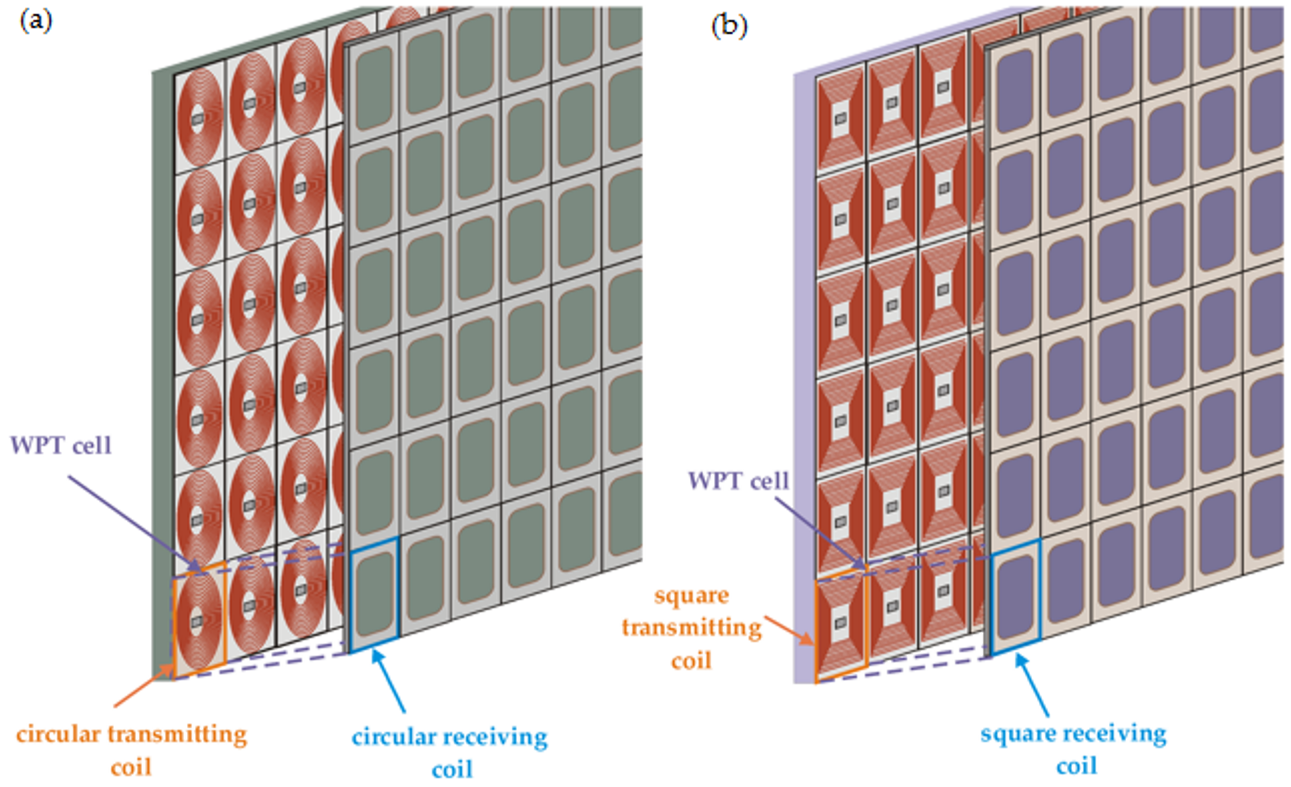
The presented WPT system had transmitting (Tx) and receiving (Rx) coils. They were organized periodically. Each Tx–Rx pair is called a WPT cell (Figure 1). The dimensions of the WPT cell were d × d. Tx and Rx had the same radius (r) and number of turns (n). The coils were wound on a non-conductive carcass. The study analysed WPT systems with two types of coils: circular and square (Figure 1a,b). Each coil had a compensation capacitor in series with the coil. The Tx coils formed the transmitting surface, and the Rx coils formed the receiving surface. Wireless energy transfer took place between these surfaces. A sinusoidal voltage source (Usc) was connected to the transmitting surface. The receiving coils were connected to the loads (Zl). Multiple receivers could be powered simultaneously.
The study presents two methods of analysis: numerical and analytical. The use of the proposed numerical approach allows one to reduce the number of degrees of freedom (NDOF) and shorten the analysis time (Section 3.1). The use of the second analysis allows one to determine the power flow already at the design stage (Section 3.2).
3. WPT System Analysis Methods
Each of the methods (analytical, numerical, experimental) had advantages and disadvantages [33,34,35]. Knowledge of the methods and needs imposed by the analysed system allows for the appropriate selection of the method of task implementation and for the elimination of errors. Knowledge of numerical methods enables the correct use of calculation packages (e.g., Matlab, Maple, Mathematica), and provides the necessary basis for the independent solving of specific, increasingly complex engineering problems [36]. This requires, on the one hand, the awareness of the essence of the problems to be solved, and on the other hand, knowledge of the methods for solving them.
In the theory of numerical methods, understanding the limitations of a given method plays a fundamental role, which, in turn, is closely related to determining the computational error [33,37,38,39,40]. By numerical task, we mean a clear and unambiguous description of the functional relationship between the input data (independent variables) and the output data (search results). An algorithm for a given numerical task is, by definition, a complete description of correctly defined arithmetic and logical operations that transform acceptable inputs into outputs. For a given numerical task, many different algorithms can be considered, which can produce results of widely varying accuracy. For this reason, it is necessary to properly select the method, the possibility of modeling the system, and assigning the conditions. Important elements in a given method include matching the mesh to the area, addressing difficulties with boundary conditions and the resulting loss of accuracy, the choice of solver, as well as limiting the model in terms of geometry or the number of degrees of freedom.
The finite element method (FEM) is a numerical method used for solving differential equations. These equations, most often, describe phenomena and processes known in nature, physics, and technology. The use of FEMs in solving technical problems results from the possibility of obtaining the result of an equation that cannot be solved analytically, or is too complex and time-consuming.
Discretization is the first step in creating the FEM model. It consists of dividing the area into smaller elements. The elements have common nodes (points), and additionally contain information about mutual proximity. Discretization is crucial in FEM issues, because it determines the extent of calculations and the accuracy of the results. Simulation of physical processes using the finite element method consists of the final stage in solving a system of algebraic equations. The number of unknowns is closely related to the number of nodes that make up the mesh, and the number of unknowns in each node. By increasing the mesh density, we increase the calculation time and, at the same time, increase the accuracy of the solution.
3.1. Analysis of the Proposed WPT Systems Using the FEM Method
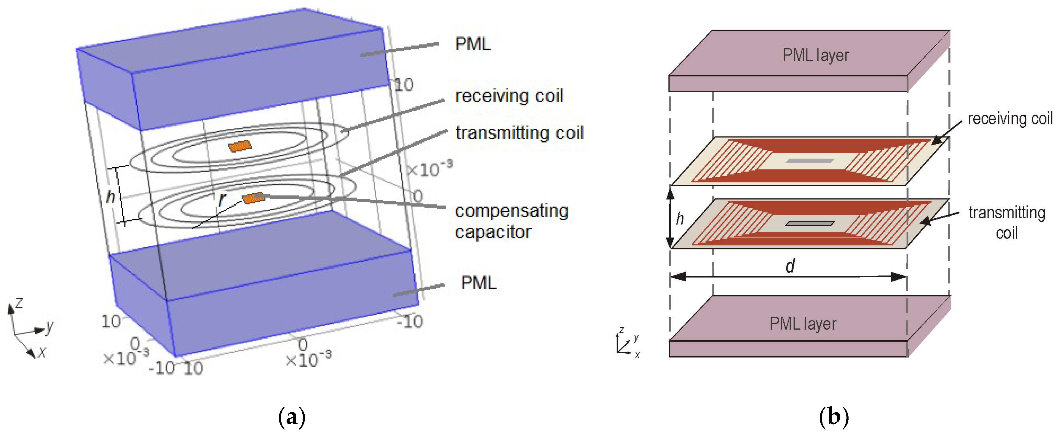
Numerical methods can be used to perform a multi-variant analysis in order to determine the distribution of the magnetic field [33,37,38]. For the analysis of the proposed WPT system, the finite element method (FEM) was used, which allows for the refinement of the mesh in selected areas. This solution allows one to reduce the number of network elements, i.e., the number of unknowns, as well as the time effects of calculations [38,39]. The proposed solution allows one to reduce the NDOF, using boundary conditions. For this reason, instead of building the entire complex model, it is enough to design a single WPT cell and apply periodic boundary conditions. In the proposed models, periodic boundary conditions were provided on surfaces parallel to the Z-axis (Figure 2). The coils were made of a very thin wire (wd), with an electrical insulator of thickness (wi). The compensation capacitor (Ccp) was modelled as a lumped element. Two layers (PML) at the top and bottom of the WPT cell were used to model the infinite dielectric background [38].
The COMSOL Multiphysics 4.3b package was used to prepare a numerical model for the proposed solution, and to perform computer simulations. COMSOL can model wave problems in the frequency domain with an add-on Radio Frequency module. A detailed description of the boundary conditions can be found in the COMSOL documentation [39,40].
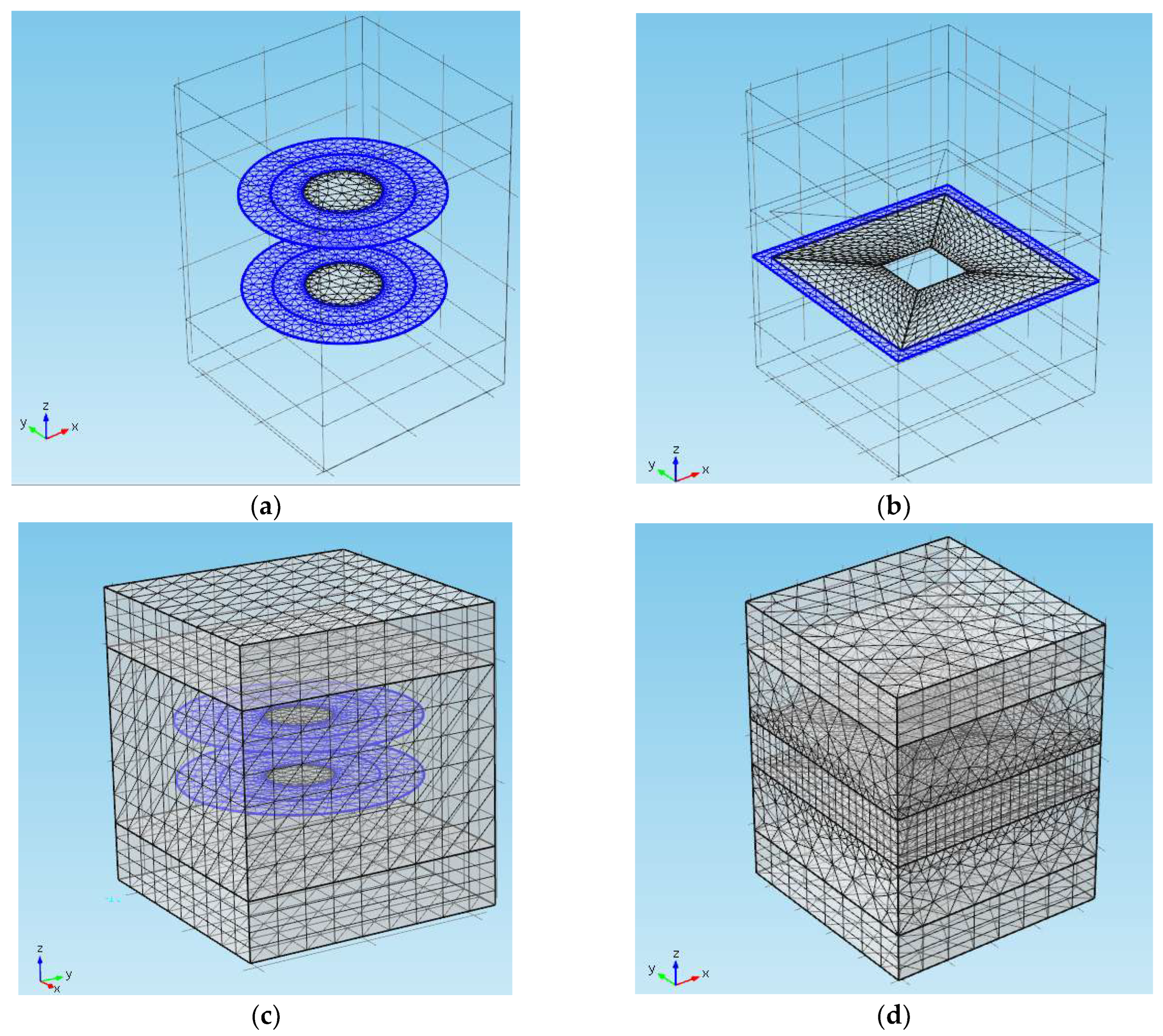
An analysis was conducted in the frequency domain, taking into account the physics of Magnetic fields in connection with a fragmentary Equivalent circuit. The coils were modeled using the built-in current sheet approximation of planar inductors (Multi-turn coil boundary condition), where the voltage source (Usc), capacitors (Ccp), and load (Zl) were connected to the coils by internal coupling with a fragmentary Equivalent circuit. In the Global Definitions, the values of the model parameters related to the copper wire from which the coil was made were entered. The names of the variables used in the geometry of the system and in the formulas were also entered. In the next step, the geometry was created in the Geometry. In the Materials, the values of air parameters that filled the WPT cell composed of the transmitting and receiving coils were entered. The Magnetic Fields describes the boundary conditions: Magnetic Insulation, which was defined on the sidewalls of the WPT cell cube. In this part, the Lumped Port was also used, which was included in the Multi-Turn Coil for both coils (transmitting and receiving). In the Electric Circuit, the source type was specified: AC-Source. An AC/DC module was used. The port was placed along the direction of current flow. This part was about connecting circuit elements, i.e., resistor, coils, source, capacitors, and the load. The active port was the source. A passive port was, for example, a resistor. In the Mesh, a mesh was selected. The elements were Free Tetrahedral and Free Triangular (Figure 3). The mesh was very dense on the surfaces of the coils. The grid was selected, so that there were at least 20 elements per wavelength.
In the Study, the frequency was specified as 1000 kHz. A solver was also chosen: direct MUMPS, which requires a large amount of RAM, but the results are obtained in a shorter time than iterative solvers. In Results and Tables, COMSOL shows the simulation results.
In the calculations, a magnetic vector potential used (Equation (1)) and the Helmholtz equation (Equation (2)):
where Jex is an external current density [A/m2] that results from a voltage supply (Usc). Equations (1) and (2) were solved by the FEM method.
The periodic boundary conditions on the four external surfaces were defined as magnetic insulation (ns × A = 0), where ns is a surface normal vector ns= [1x 1y 1z]. During calculations in COMSOL, the model in the form of a single cell was copied indefinitely to the left and right, and then the whole configuration was copied indefinitely down and up. Then, COMSOL calculated the distribution of the electromagnetic field at each point on the surface of the coil (more precisely, the magnetic vector potential was calculated A). On this basis, the induced voltages and currents were calculated. Based on these values, COMSOL further calculated, e.g., power, energy, efficiency, impedance, and more.
The analyzed models are presented in Table 1. The calculations were performed at the frequency of 1000 kHz, at distances h = r/2 and h = r for the small and large coils. The following parameter values were used: wd = 200 µm, wi = 5 µm, σc = 5.6·107 S/m, and Usc = 1 V. The influence of the load resistance (Zl = Ro) on the power and efficiency of the WPT system was investigated.
3.2. Analytical Method Used in the Analysis of WPT Systems
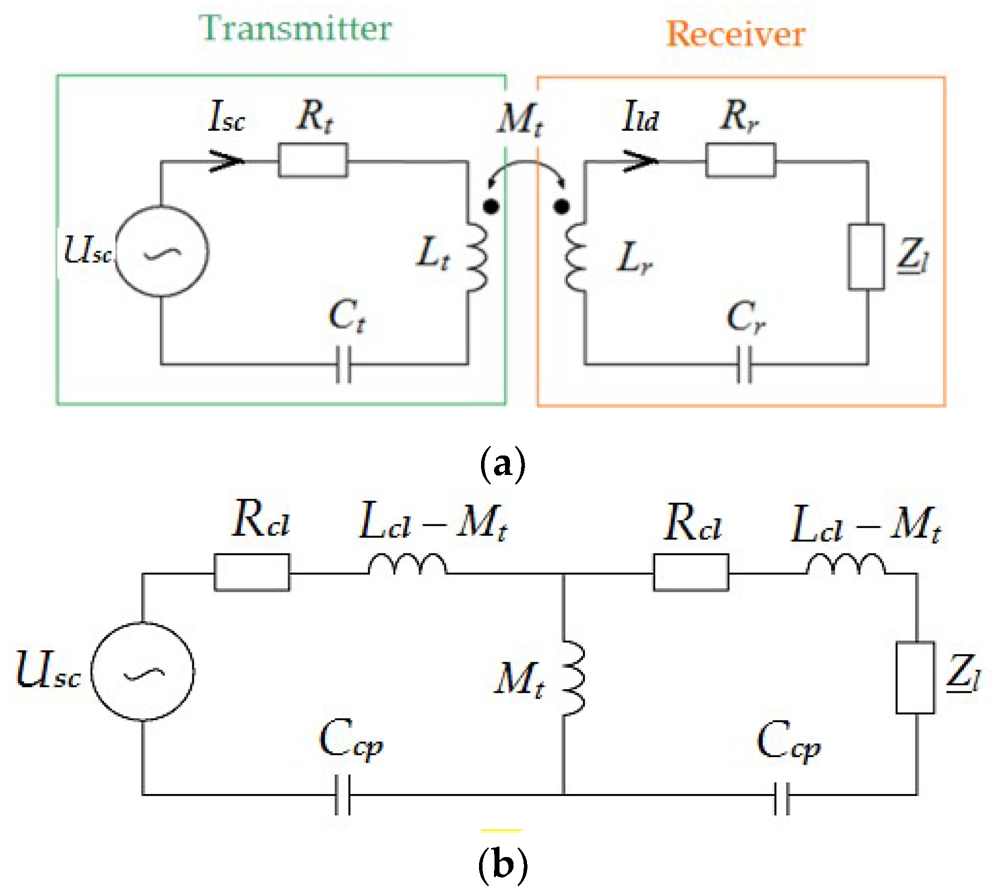
Preparation of the numerical model and the application of boundary conditions or proper discretization of the model of the proposed WPT periodic system is a complex task. The ability to run computer simulations does not mean that a given task cannot be solved by another method. In this case, a simpler model could be proposed, which is an analytical solution. Figure 4 shows an analytical model that combines a two-port network with the presented formulas.
A similar approach was used as in the numerical model, i.e., an infinite periodic grid was simplified for the analysis of a single WPT cell. The circuit model solution focused on determining the values of several lumped parameters. In this approach, it was necessary to consider the influence of neighbouring cells on the inductances Lt and Lr of the coils TR and RE, respectively, and their mutual inductance Mt. In an electrical circuit, the analysis of an infinite periodic network can be reduced to a single cell Ax,y.
As in the numerical solution, the system consisted of the same coils arranged at a distance h. The coils were made of a thin wire with electrical conductivity σc. The length of turns in a circular coil is described by Equation (3), and for a square coil by Equation (4):
Since the coils were identical, we assumed that both resistances were equal; therefore, Rt = Rr = Rcl. The equation for the resistance Rcl of a circular coil is as follows:
For a square coil, the resistance is represented by the following:
The mutual inductances of the coil (Ax,y) and the coils (Ax+m,y+n) affect the internal inductance of the coil (Ax,y), which for circular and square coils can be represented by the following:
where Lcl—effective inductance in (H); Mx+m,y+n—mutual inductance (H) between coils adjacent in the horizontal plane; Lsf—self-inductance in (H), and it is calculated from Equation (8) [41,42,43], where dm—mean diameter and ν—fill factor:
Coefficients k1, k2, k3, and k4 depend on the shape of the coil. The assumed coefficients for calculations for circular coils were k1 = 1, k2 = 2.5, k3 = 0, k4 = 0.2; for square coils, the coefficients were k1 = 1.46, k2 = 1.9, k3 = 0.18, k4 = 0.13 [42,43]. The effective inductance of the coil is determined as follows:
where Mpc is the sum of mutual inductances in the periodic grid, because it reduces the inductance of the coil, it is with a minus. When the load Zl = ∞ and there is no capacitor in series with the transmitting coils, Mpc is given by the following:
where Isc,∞ = |Isc,∞|ejψ—source current in [A]; ψ—phase angle between source voltage and current in [rad]. Considering Figure 4b, instead of calculating Mr,x+m,y+n, the mutual inductance Mt between the coils (Tx, Rx) can be calculated from the following formula [32,41]:
where Uld,∞ = |Uld,∞|ejθ—voltage induced in Rx coil in V, and θ—phase angle between source voltage and voltage induced in rad. The compensating capacity (Ccp) is calculated from the following:
The distance (h) reduced a mutual inductance Mt. On the other hand, Mpc was constant, regardless of the frequency and distance h, since it was the mutual inductance of the considered and adjacent coil in the same periodic grid. According to Equations (7) and (11), Mpc affects the effective inductance. However, the Mpc for all models was known from the initial simulations, and was included in the main simulations. Finally, if we assume (as in the case of an air-core transformer) that the series Ccp does not depend on the mutual inductance of the primary and secondary sides, then Mt and h can be omitted in Equation (14).
Based on the obtained power and efficiency values of the WPT system, the results of both proposed solutions were compared. The active power of the coil Rx is represented in Equation (15), and the coil Tx power is calculated from Equation (16):
The power transfer efficiency is calculated from the following:
In addition, the load resistance for the circular and square coils is calculated, in terms of the following:
- -
- the system obtains maximum efficiency (η_max):
- -
- the system obtains maximum receiver power (Pld_max):
All parameters are the same as in the numerical model.
4. Analysis of the Results Obtained by Two Methods
The analysed models of the WPT system are presented in Table 1, which were presented in Section 3.1. The results obtained by numerical and analytical methods were compared. The influence of the load resistance on the power and efficiency of the WPT system (circular and square) was investigated. For each case, a range of load resistance Ro was selected to perform the most accurate analysis. Calculations were made at a frequency of 1000 kHz, at distances h = 0.5r and h = r for the small and large coils. The results obtained by both methods were compared, and the differences did not exceed 1%.
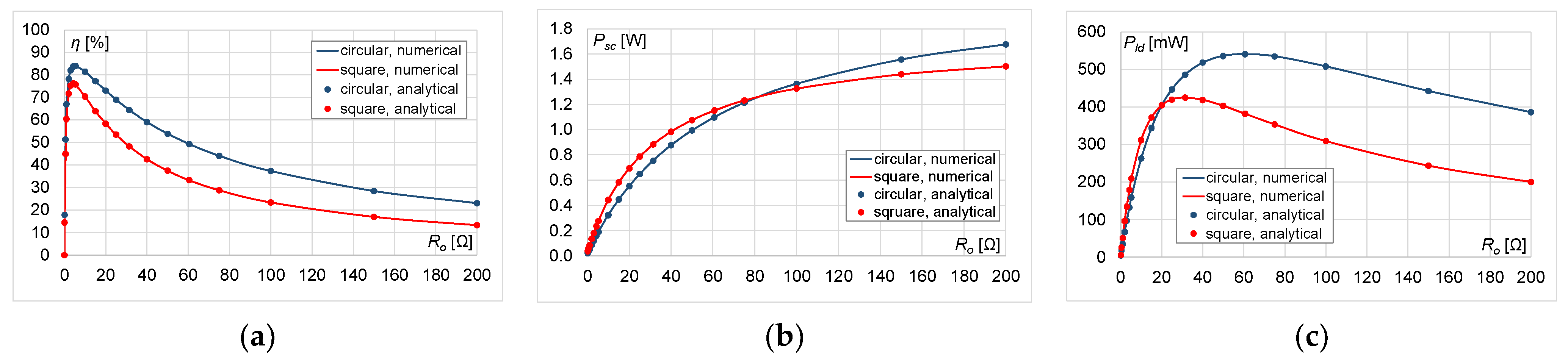
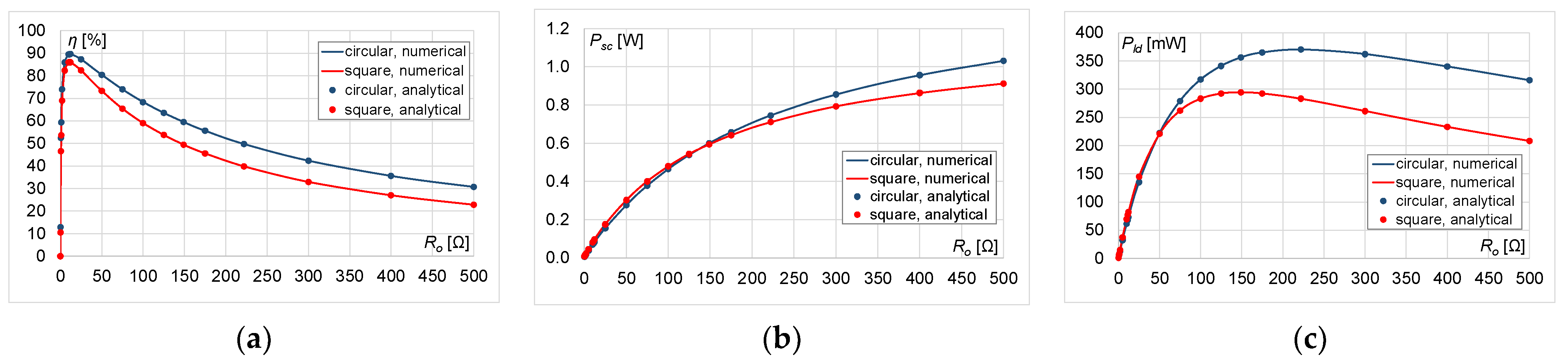
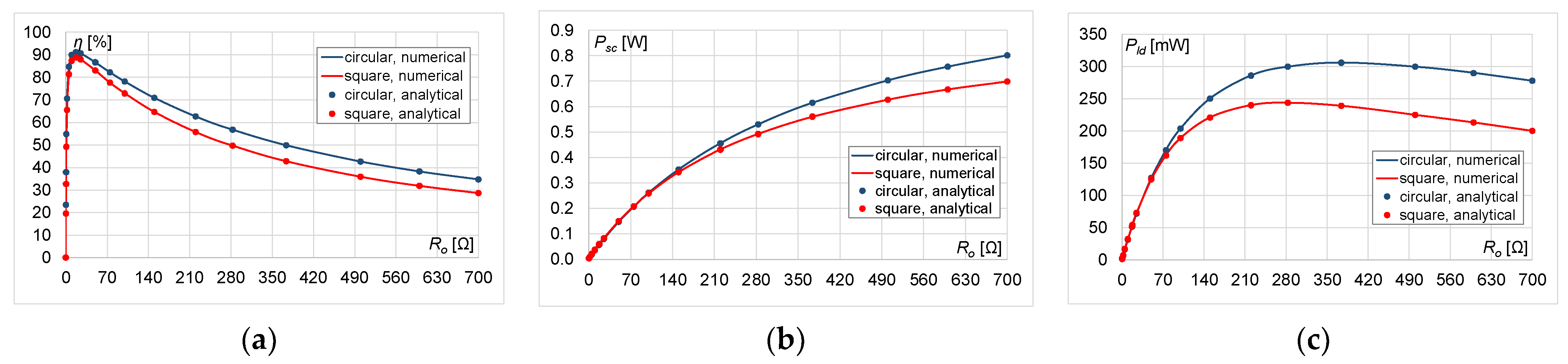
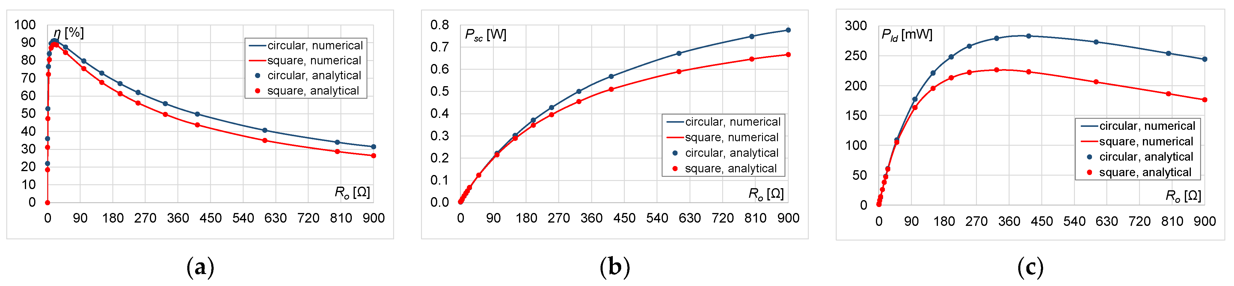
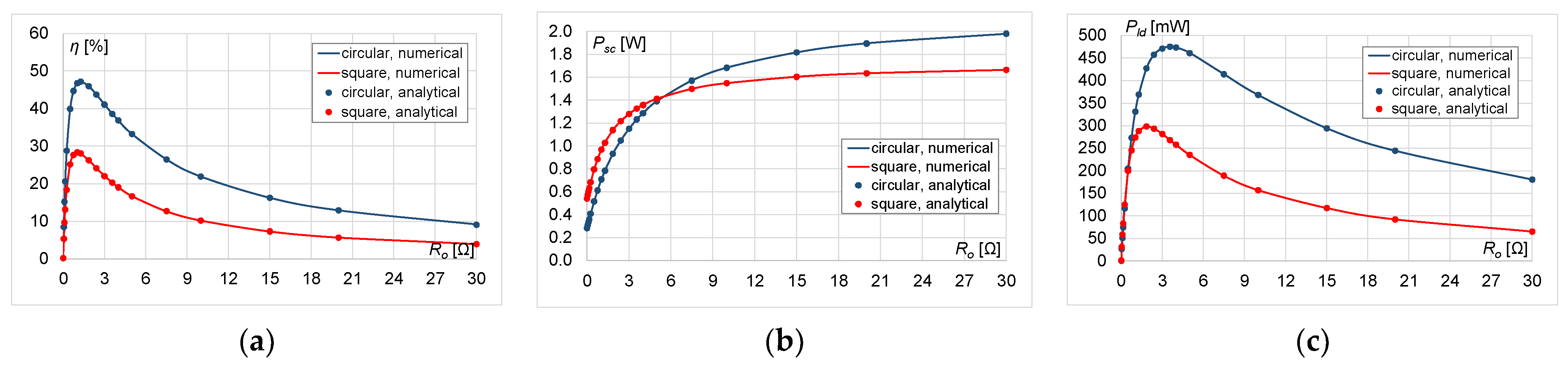
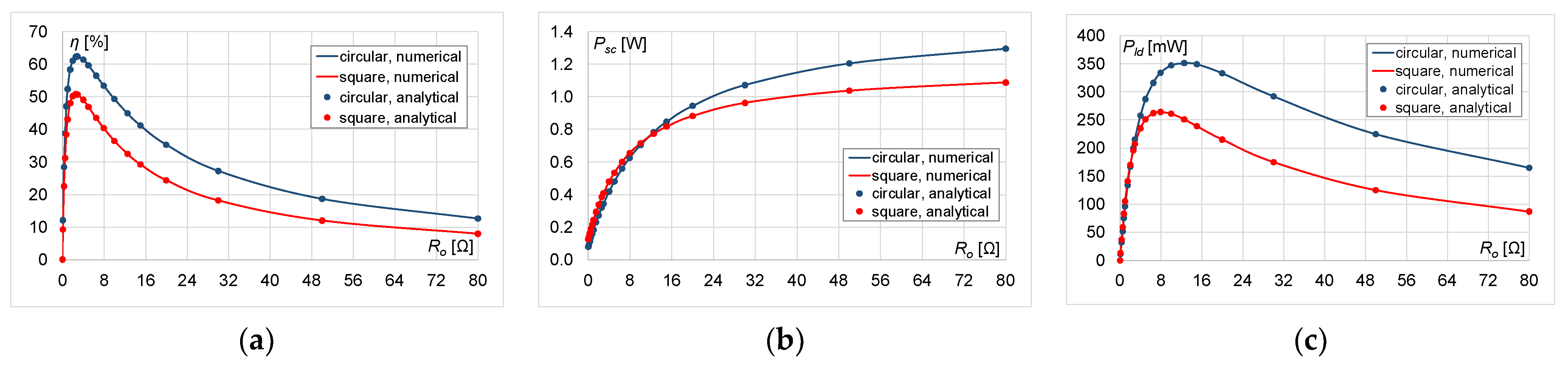
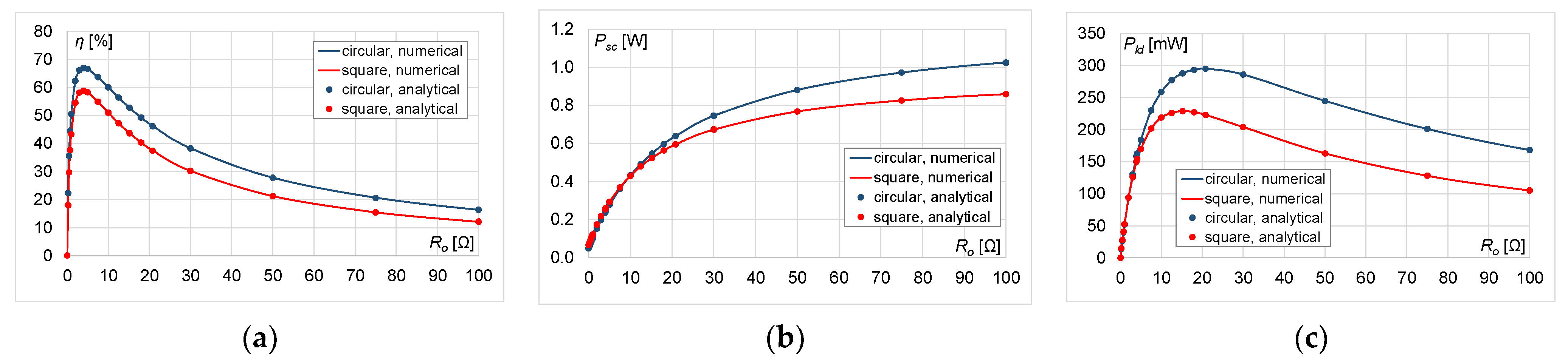
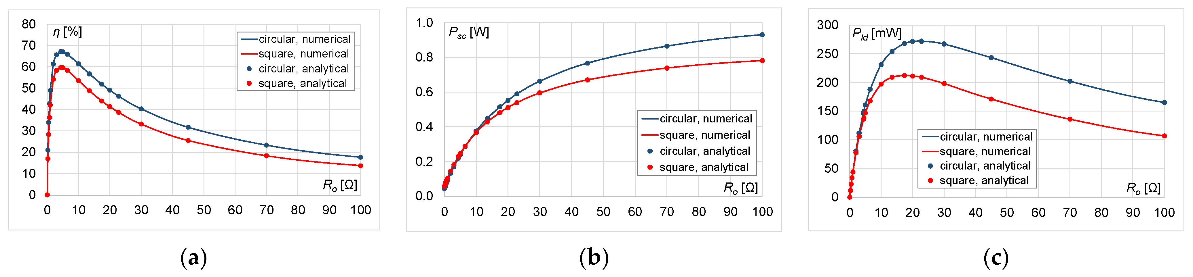
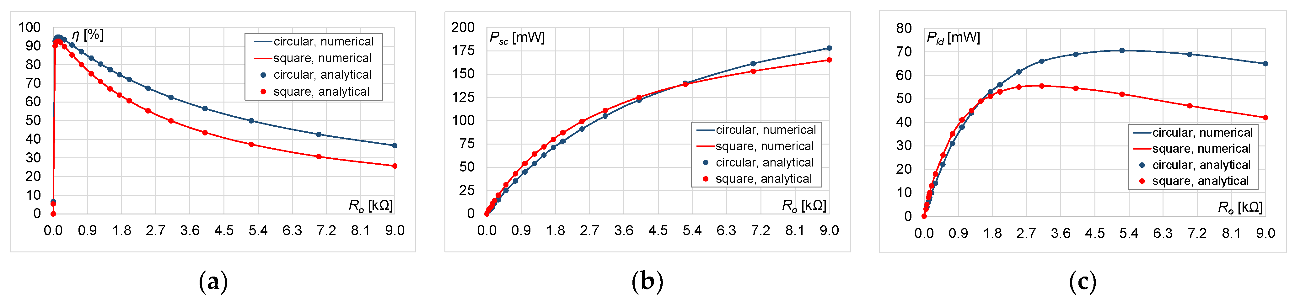
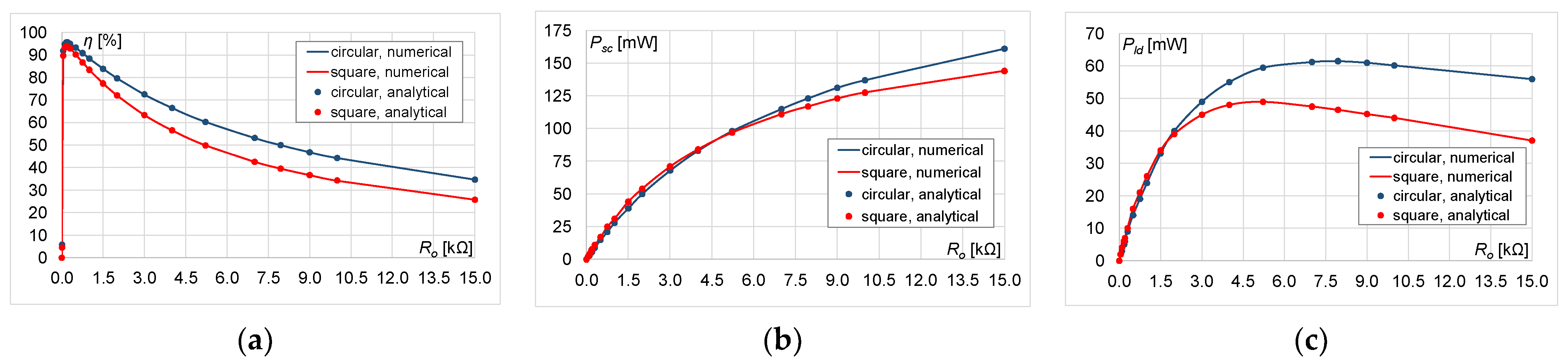
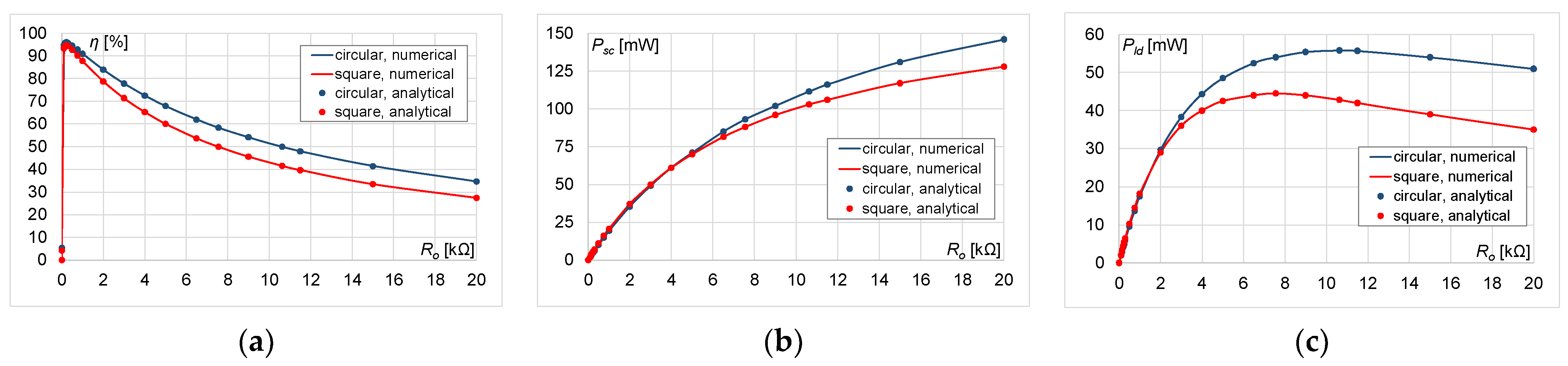
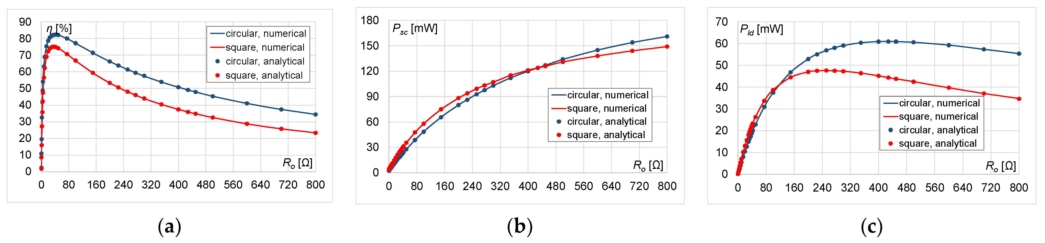
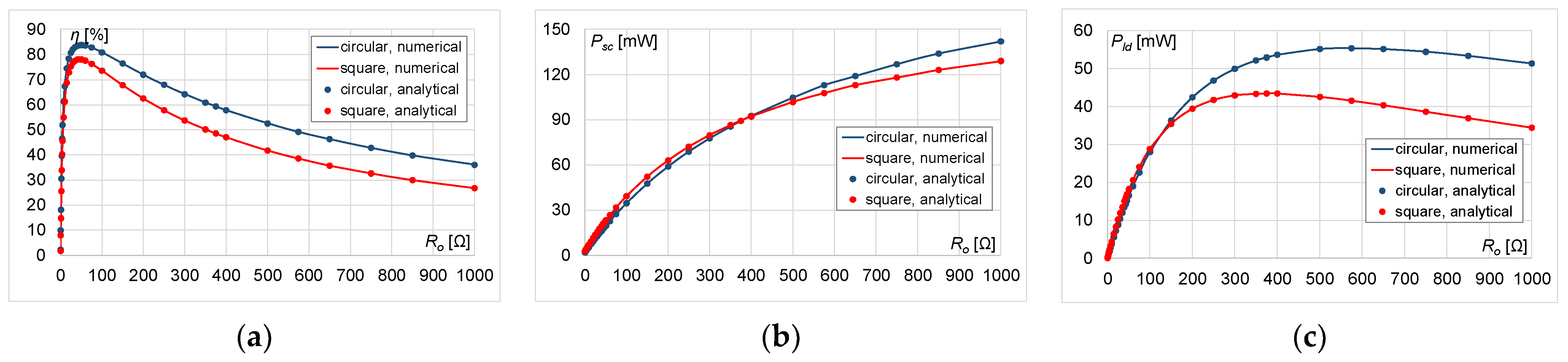
Characteristics: power transfer efficiency, and transmitter and receiver powers are shown in the diagrams in Section 4.1 for a small coil, and in Section 4.2 for a large coil. The results of the numerical analysis are presented as solid lines (marked as numerical in the legend). The results of the analytical analysis are shown as dots (marked as analytical in the legend).
4.1. Small Coil
This part compares the calculation results of the analysed WPT systems obtained by analytical and numerical methods for a small coil.
4.1.1. Results for a Small Coil at h = 0.5r = 0.005 m
The efficiency, transmitter and receiver powers graphs are presented in Figure 5, Figure 6, Figure 7 and Figure 8.
The results presented above show that higher power and efficiency values were obtained for the circular coil model. With increasing numbers of turns, this difference became smaller. The shape of the characteristics was maintained, regardless of the number of turns n. With an increase in the number of turns, the range of load resistance Ro increased, in which the efficiency exceeded 50% (Figure 5a, Figure 6a, Figure 7a and Figure 8a). For n = 15, 25, and at low load resistance values, the transmitter power Psc was higher for a square coil than for a circular one. For higher values of Ro, the opposite was true, regardless of the number of turns (Figure 5b, Figure 6b, Figure 7b and Figure 8b). The power transfer efficiency or receiver power Pld increased as the load resistance increased, and then began to decrease after reaching its maximum value. With an increase in the number of turns, higher values of Ro resulted in maximum receiver power Pld and maximum efficiency. In addition, the difference in efficiency or receiver power for circular and square coils became smaller (Figure 5c, Figure 6c, Figure 7c and Figure 8c).
4.1.2. Results for a Small Coil at h = r = 0.01 m
The efficiency, and transmitter and receiver powers graphs are presented in Figure 9, Figure 10, Figure 11 and Figure 12.
Doubling the distance h resulted in an increase in the maximum transmitter power Psc and a decrease in the maximum receiver power Pld, regardless of the analysed case (Figure 9b,c, Figure 10b,c, Figure 11b,c and Figure 12b,c). The power transfer efficiency η also decreased, with the largest decrease in the value occurring for n = 15 (Figure 9a). In this case, the efficiency did not exceed 30% for a square coil (a decrease of more than two times) and 50% for a circular coil. The range of load resistance Ro, in which the efficiency exceeded 50%, also decreased (Figure 9a, Figure 10a, Figure 11a and Figure 12a). The maximum values of efficiency and receiver power were obtained for lower values of the load resistance compared to the smaller distance h (Figure 9c, Figure 10c, Figure 11c and Figure 12c). The shape of the characteristics was preserved, regardless of the number of turns n. Higher power and efficiency values were obtained for the model with a circular coil than with a square one. The greatest difference occurred for n = 15. With increasing numbers of turns, this difference became smaller. As with the smaller distance h, with an increase in the number of turns, the maximum efficiency and receiver power were obtained at higher load resistance values.
4.2. Large Coil
This part compares the calculation results of the analysed WPT systems obtained by analytical and numerical methods for a large coil.
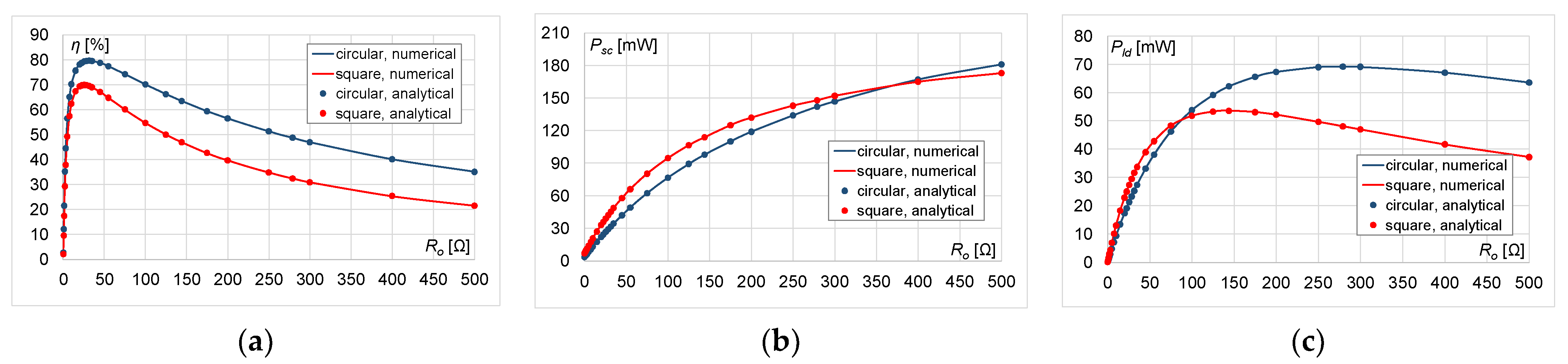
4.2.1. Results for a Large Coil at h = 0.5r = 0.0125 m
The efficiency, transmitter and receiver powers graphs are presented in Figure 13, Figure 14 and Figure 15. The power transfer efficiency and receiver power Pld increased with increasing load resistance; then, after reaching the maximum value, they began to decrease (Figure 13a,c, Figure 14a,c and Figure 15a,c). With an increase in the number of turns, the same efficiency value was obtained with a higher load resistance Ro. The maximum efficiency value was comparable for both types of coils. As in the case of the smaller coil, higher efficiency values were obtained for the circular coil model (Figure 13a, Figure 14a and Figure 15a).
With increasing numbers of turns, this difference became smaller. Regardless of the number of turns and at low Ro values, the transmitter power Psc was higher for a square coil than for a circular one (Figure 13b, Figure 14b and Figure 15b). At higher load resistance values, the opposite was true, and this difference decreased with increasing numbers of turns. The range of load resistance where the efficiency exceeded 50% increased with the number of turns (Figure 13a, Figure 14a and Figure 15a). The shape of the characteristics was maintained, regardless of n.
4.2.2. Results for a Large Coil at h = r = 0.025 m
The efficiency, transmitter and receiver powers graphs are presented in Figure 16, Figure 17 and Figure 18.
Doubling the distance h resulted in a decrease in the maximum efficiency and maximum receiver power Pld, regardless of the analysed case (Figure 16a,c, Figure 17a,c and Figure 18a,c). The largest decrease in the efficiency value occurred for n = 50 (Figure 16a): for a square coil it exceeded 22%, and for a circular coil it exceeded 15%. Higher efficiency values were obtained for the circular coil model than for the square one. The greatest difference occurred for n = 50. With increasing numbers of turns, this difference decreased. With an increase in n, the maximum efficiency and receiver power values were obtained with a higher load resistance. The maximum values of efficiency and receiver power were obtained with lower load resistance values compared to the smaller distance between the coils h (Figure 16a,c, Figure 17a,c and Figure 18a,c). The range of load resistance Ro in which the efficiency exceeded 50% also decreased (Figure 16a, Figure 17a and Figure 18a). At low load resistance values, the receiver and transmitter powers were higher for a square coil than for a circular one (Figure 16b,c, Figure 17b,c and Figure 18b,c). With increasing numbers of turns, this difference became smaller. At higher load resistance values, the receiver and transmitter powers were higher for a circular coil than for a square one. With increasing numbers of turns, this difference increased for the transmitter power (Figure 16b, Figure 17b and Figure 18b) and decreased for the receiver power (Figure 16c, Figure 17c and Figure 18c). The shape of the characteristics was maintained, regardless of the number of turns.
4.3. Comparison of the Obtained Maximum Values
The values of the maximum receiver power and the maximum efficiency of the WPT system, depending on the number of turns n and the distance h and the corresponding values of the load resistance Ro for circular and square coils, were compared in Table 2 at the distance h = r/2, and in Table 3 at h = r.
With increasing numbers of turns, the maximum efficiency η_max increased, but the maximum receiver power Pld_max decreased. The load resistance Ro also increased, at which η_max and Pld_max were obtained. This is because the equivalent resistance of the analysed system increased with an increase in the number of turns. The load resistance at which the maximum receiver power is obtained was higher than the load resistance at which the maximum system efficiency was obtained. Higher values were obtained for a circular coil. The largest difference in maximum efficiency occurred for n = 15 and 50, and decreased with increasing numbers of turns. The load resistance was higher for a circular coil than for a square one. The largest difference occurred for n = 15 and 50, and decreased with an increase in the number of turns.
Doubling the distance h resulted in a significant decrease in the maximum efficiency η_max for both types of coils (the largest decrease occurred for the small coil for n = 15: almost 40% for the circular coil, and almost 50% for the square one). In addition, the maximum receiver power Pld_max decreased the most for the small coil, regardless of the type of coils used (also the most for n = 15). For the large coil, doubling the distance h resulted in a very small decrease in the maximum receiver power Pld_max for both types of coils, and a decrease of over 10% in the maximum efficiency η_max for the circular coil, and an over 15% decrease for the square one. Higher values of η_max and Pld_max were obtained for the circular coil. For this coil, the corresponding values of the load resistance Ro were also higher.
The ranges of load resistance Ro were compared, in which the efficiency of the WPT system exceeded 50% for circular and square coils, as seen in Table 4 at h = r/2, and as seen in Table 5 at h = r. The tables show the range of load resistances in which the efficiency of the WPT system exceeded 50%; as based on the literature (refer to Introduction), it can be concluded that this is the range that allows for effective operation of the WPT system.
With increasing numbers of turns, the range of the load resistance Ro increased, in which the efficiency of the WPT system exceeded 50%. Higher ranges of load resistance values were obtained for a circular coil than for a square one. For n = 15, this difference was double. With increasing numbers of turns, this difference decreased for large and small coils.
Doubling the distance h resulted in a significant decrease in the range of load resistance Ro values, in which the efficiency of the WPT system exceeded 50% for both types of coils. The largest decrease was for n = 25 (more than 20 times). For the number of turns equal to 15, the WPT system did not reach 50% efficiency at all for both types of coils. Higher ranges of load resistance values were obtained for a circular coil than for a square one. For n = 25, this difference was five-fold. With increasing numbers of turns, this difference decreased for large and small coils.
5. Conclusions
The idea of wireless energy transmission has been talked about for many years. In recent years, however, there has been a growing trend towards practical applications of WPT.
In this study was presented a WPT system with a periodic distribution of low-power planar coils (circular and square). A multi-variant analysis was carried out in order to find the load resistance values at which the system efficiency is the highest. The analysis took into account the variability in the number of turns, the size of the coils, the shape of the coils, and the distance between the transmitting and receiving coils. The proposed use of an equivalent circuit, represented by a single WPT cell, yielded a simpler and faster solution. The applied analysis methods could be used to assess the properties of the WPT system and its related parameters.
The research presented the numerical and analytical analysis of the WPT system at a frequency of 1000 kHz. The influence of load resistance changes on the power and efficiency of circular and square coils was investigated. The results showed that higher maximum efficiency results were obtained for the model with a circular coil than with a square one, and the difference did not exceed 19%. For a system with a square coil, there was an almost two-fold decrease in the maximum efficiency of the system (maximum efficiency did not exceed 30% for a square coil and 50% for a circular one). This relationship was observed when the distance between the transmitting and receiving coils was doubled. Depending on the size of the coil and the number of turns, the load resistance values varied. With an increase in these parameters, the load resistance values increased, at which the maximum efficiency and receiver power were obtained. Increasing the distance between the coils in the WPT system reduced the value of the load resistance at which the maximum efficiency and receiver power were obtained. The obtained results can be used in the design of WPT systems by choosing the load resistance value in such a way as to obtain the highest efficiency or receiver power values.
Further research will concern the implementation of numerical and analytical models for other coil shapes (e.g., pentagonal). On this basis, the influence of the shape and size of the coil, the number of turns, the distance between the coils, and the frequency on the parameters of the WPT system will be analysed. Another direction of research will be to consider the possibility of using metamaterials in the proposed WPT systems, in order to increase the efficiency of the system. Since the systems of planar coils proposed in this study were made on a flexible substrate, the influence of bending of the transmitting/receiving surface on the efficiency of the system will also be analysed.
Funding
The printing of the article was financed from the ZIREG project–Integrated Program of the Bialystok University of Technology for Regional Development, contract no. POWR.03.05.00-00-ZR22/18. Project co-financed by the European Union from the European Social Fund under the Knowledge Education Development Operational Program 2014–2020.
Data Availability Statement
Not applicable.
Conflicts of Interest
The author declares no conflict of interest.
References
- Barman, S.D.; Reza, A.W.; Kumar, N.; Karim, M.E.; Munir, A.B. Wireless powering by magnetic resonant coupling: Recent trends in wireless power transfer system and its applications. Renew. Sustain. Energy Rev. 2015, 51, 1525–1552. [Google Scholar] [CrossRef]
- Sun, L.; Ma, D.; Tang, H. A review of recent trends in wireless power transfer technology and its applications in electric vehicle wireless charging. Renew. Sustain. Energy Rev. 2018, 91, 490–503. [Google Scholar] [CrossRef]
- Yang, Y.; El Baghdadi, M.; Lan, Y.; Benomar, Y.; Van Mierlo, J.; Hegazy, O. Design Methodology, Modeling, and Comparative Study of Wireless Power Transfer Systems for Electric Vehicles. Energies 2018, 11, 1716. [Google Scholar] [CrossRef] [Green Version]
- Xun, J.-H.; Mu, Y.; Zhang, K.; Liu, H.; Li, L. The Efficiency Improvement of Multiple Receivers in Wireless Power Transmission by Integrating Metasurfaces. Materials 2022, 15, 6943. [Google Scholar] [CrossRef] [PubMed]
- Luo, Z.; Wei, X. Analysis of square and circular planar spiral coils in wireless power transfer system for electric vehicles. IEEE Trans. Ind. Electron. 2018, 65, 331–341. [Google Scholar] [CrossRef]
- Batra, T.; Schaltz, E.; Ahn, S. Effect of ferrite addition above the base ferrite on the coupling factor of wireless power transfer for vehicle applications. J. Appl. Phys. 2015, 117, 17D517. [Google Scholar] [CrossRef]
- Eteng, A.A.; Rahim, S.K.A.; Leow, C.Y.; Chew, B.W.; Vandenbosch, G.A.E. Two-Stage Design Method for Enhanced Inductive Energy Transmission with Q-Constrained Planar Square Loops. PLoS ONE 2016, 11, e0148808. [Google Scholar] [CrossRef] [Green Version]
- Kim, T.-H.; Yun, G.-H.; Lee, W.Y. Asymmetric Coil Structures for Highly Efficient Wireless Power Transfer Systems. IEEE Trans. Microw. Theory. Tech. 2018, 66, 3443–3451. [Google Scholar] [CrossRef]
- Tang, S.C.; Lun, T.L.T.; Guo, Z.; Kwok, K.W.; McDannold, N.J. Intermediate range wireless power transfer with segmented coil transmitters for implantable heart pumps. IEEE Trans. Power Electron. 2017, 32, 3844–3857. [Google Scholar] [CrossRef]
- Choroszucho, A.; Butryło, B. Local attenuation of electromagnetic field generated by wireless communication system inside the building. Przegląd Elektrotechniczny 2011, 87, 123–127. [Google Scholar]
- Rim, C.T.; Mi, C. Wireless Power Transfer for Electric Vehicles and Mobile Devices; John Wiley & Sons, Ltd.: Hoboken, NJ, USA, 2017; pp. 473–490. [Google Scholar]
- Fujimoto, K.; Itoh, K. Antennas for Small Mobile Terminals, 2nd ed.; Artech House: Norwood, MA, USA, 2018; pp. 30–70. [Google Scholar]
- Sołjan, Z.; Zajkowski, M. Extension and Correction of Budeanu Power Theory Based on Currents’ Physical Components (CPC) Theory for Single-Phase Systems. Energies 2022, 15, 8321. [Google Scholar] [CrossRef]
- Zhang, Z.; Pang, H.; Georgiadis, A.; Cecati, C. Wireless Power Transfer—An Overview. IEEE Trans. Ind. Electron. 2019, 66, 1044–1058. [Google Scholar] [CrossRef]
- Rozman, M.; Fernando, M.; Adebisi, B.; Rabie, K.M.; Collins, T.; Kharel, R.; Ikpehai, A. A New Technique for Reducing Size of a WPT System Using Two-Loop Strongly-Resonant Inductors. Energies 2017, 10, 1614. [Google Scholar] [CrossRef] [Green Version]
- Liu, X.; Wang, G. A Novel Wireless Power Transfer System with Double Intermediate Resonant Coils. IEEE Trans. Ind. Electron. 2016, 63, 2174–2180. [Google Scholar] [CrossRef]
- El Rayes, M.M.; Nagib, G.; Abdelaal, W.G.A. A Review on Wireless Power Transfer. IJETT 2016, 40, 272–280. [Google Scholar] [CrossRef]
- Re, P.D.H.; Podilchak, S.K.; Rotenberg, S.; Goussetis, G.; Lee, J. Circularly Polarized Retrodirective Antenna Array for Wireless Power Transmission. In Proceedings of the 2017 11th European Conference on Antennas and Propagation (EUCAP), Paris, France, 19–24 March 2017; pp. 891–895. [Google Scholar]
- Nikoletseas, S.; Yang, Y.; Georgiadis, A. Wireless Power Transfer Algorithms, Technologies and Applications in Ad Hoc Communication Networks; Springer: Cham, Switzerland, 2016; pp. 31–51. [Google Scholar]
- Stevens, C.J. Magnetoinductive waves and wireless power transfer. IEEE Trans. Power Electron. 2015, 30, 6182–6190. [Google Scholar] [CrossRef]
- Steckiewicz, A.; Choroszucho, A. Optimization-based synthesis of a metamaterial electric cloak using nonhomogeneous composite materials. J. Electromagn. Waves Appl. 2019, 33, 1933–1941. [Google Scholar] [CrossRef]
- Zhong, W.; Lee, C.K.; Hui, S.Y.R. General analysis on the use of Tesla’s resonators in domino forms for wireless power transfer. IEEE Trans. Ind. Electron. 2013, 60, 261–270. [Google Scholar] [CrossRef] [Green Version]
- Alberto, J.; Reggiani, U.; Sandrolini, L.; Albuquerque, H. Accurate calculation of the power transfer and efficiency in resonator arrays for inductive power transfer. PIER 2019, 83, 61–76. [Google Scholar] [CrossRef] [Green Version]
- Wang, B.; Yerazunis, W.; Teo, K.H. Wireless Power Transfer: Metamaterials and Array of Coupled Resonators. Proc. IEEE 2013, 101, 1359–1368. [Google Scholar] [CrossRef] [Green Version]
- Nguyen, B.X.; Vilathgamuwa, D.M.; Foo, G.; Ong, A.; Sampath, P.K.; Madawala, U.K. Cascaded multilevel converter based bidirectional inductive power transfer (BIPT) system. In Proceedings of the 2014 International Power Electronics Conference (IPEC-Hiroshima 2014—ECCE ASIA), Hiroshima, Japan, 18–21 May 2014; pp. 2722–2728. [Google Scholar]
- Hao, H.; Covic, G.A.; Boys, J.T. A parallel topology for inductive power transfer power supplies. IEEE Trans. Power Electron. 2014, 29, 1140–1151. [Google Scholar] [CrossRef]
- Mai, R.; Lu, L.; Li, Y.; Lin, T.; He, Z. Circulating Current Reduction Strategy for Parallel-Connected Inverters Based IPT Systems. Energies 2017, 10, 261. [Google Scholar] [CrossRef] [Green Version]
- He, H.; Liu, Y.; Wei, B.; Wu, X.; Jiang, C.; Jiang, B.; Wei, C. Phase synchronization and current sharing strategy for multiple overlapped transmitters IPT system. Energy Rep. 2022, 8, 1103–1111. [Google Scholar] [CrossRef]
- Fitzpatrick, D.C. Implantable Electronic Medical Devices; Academic Press: San Diego, CA, USA, 2014; pp. 7–35. [Google Scholar]
- Stankiewicz, J.M.; Choroszucho, A. Comparison of the efficiency and load power in periodic Wireless Power Transfer systems with circular and square planar coils. Energies 2021, 14, 4975. [Google Scholar] [CrossRef]
- Steckiewicz, A.; Stankiewicz, J.M.; Choroszucho, A. Numerical and Circuit Modeling of the Low-Power Periodic WPT Systems. Energies 2020, 13, 2651. [Google Scholar] [CrossRef]
- Stankiewicz, J.M.; Choroszucho, A. Efficiency of the Wireless Power Transfer System with Planar Coils in the Periodic and Aperiodic Systems. Energies 2022, 15, 115. [Google Scholar] [CrossRef]
- Chapra, S.; Canale, R. Numerical Methods for Engineers, 8th ed.; MC Graw Hill: New York, NY, USA, 2021; ISBN10: 1264150105. [Google Scholar]
- Geng, Y.; Wang, T.; Xie, S.; Yang, Y. Analysis and Design of Wireless Power Transfer Systems Applied to Electrical Vehicle Supercapacitor Charge Using Variable-Resistance-Based Method. Energies 2022, 15, 5867. [Google Scholar] [CrossRef]
- Sha, L.; Liu, J.; Chen, Z. Research on Evaluation Method of Electric Vehicle Wireless Charging Interoperability Based on Two Parameter Representation. Processes 2022, 10, 1591. [Google Scholar] [CrossRef]
- Torkman, H.; Fakhari, M.; Karimi, H.; Taheri, B. New Frequency Modulation Strategy with SHE for H-bridge Multilevel inverters. In Proceedings of the 2018 4th International Conference on Electrical Energy Systems (ICEES), Chennai, India, 7–9 February 2018. [Google Scholar]
- Taflove, A.; Hagness, S.C. Computational Electrodynamics: The Finite—Difference Time—Domain Method; Artech House: Boston, MA, USA, 2005. [Google Scholar]
- Zienkiewicz, O.C.; Taylor, R.L.; Zhu, J.Z. The Finite Element Method: Its Basis & Fundamentals, 7th ed.; Butterworth-Heinemann: Oxford, UK, 2013. [Google Scholar]
- COMSOL. Introduction to the RF Module; Version: COMSOL 4.3b; COMSOL Inc.: Burlington, MA, USA, 2013. [Google Scholar]
- COMSOL. RF Module User’s Guide; Version: COMSOL 4.3b; COMSOL Inc.: Burlington, MA, USA, 2013. [Google Scholar]
- Mohan, S.S.; del Mar Hershenson, M.; Boyd, S.P.; Lee, T.H. Simple Accurate Expressions for Planar Spiral Inductances. IEEE J. Solid-State Circuits 1999, 34, 1419–1424. [Google Scholar] [CrossRef] [Green Version]
- Raju, S.; Wu, R.; Chan, M.; Yue, C.P. Modeling of Mutual Coupling Between Planar Inductors in Wireless Power Applications. IEEE Trans. Power Electron. 2014, 29, 481–490. [Google Scholar] [CrossRef]
- Liu, S.; Su, J.; Lai, J. Accurate Expressions of Mutual Inductance and Their Calculation of Archimedean Spiral Coils. Energies 2019, 12, 2017. [Google Scholar] [CrossRef] [Green Version]
Figure 1.
The analysed periodic WPT system with planar coils: (a) circular, (b) square.

Figure 2.
Geometry of the numerical model with (a) circular coils, (b) square coils.

Figure 3.
Mesh used in FEM on (a) circular coils, (b) square coils, (c) WPT cell with circular coils, (d) WPT cell with square coils.
Figure 3.
Mesh used in FEM on (a) circular coils, (b) square coils, (c) WPT cell with circular coils, (d) WPT cell with square coils.

Figure 4.
Analytical model with (a) periodic cell, (b) equivalent circuit.

Figure 5.
Results for n = 15: (a) η, (b) Psc, (c) Pld.

Figure 6.
Results for n = 25: (a) η, (b) Psc, (c) Pld.

Figure 7.
Results for n = 35: (a) η, (b) Psc, (c) Pld.

Figure 8.
Results for n = 45: (a) η, (b) Psc, (c) Pld.

Figure 9.
Results for n = 15: (a) η, (b) Psc, (c) Pld.

Figure 10.
Results for n = 25: (a) η, (b) Psc, (c) Pld.

Figure 11.
Results for n = 35: (a) η, (b) Psc, (c) Pld.

Figure 12.
Results for n = 45: (a) η, (b) Psc, (c) Pld.

Figure 13.
Results for n = 50: (a) η, (b) Psc, (c) Pld.

Figure 14.
Results for n = 60: (a) η, (b) Psc, (c) Pld.

Figure 15.
Results for n = 70: (a) η, (b) Psc, (c) Pld.

Figure 16.
Results for n = 50: (a) η, (b) Psc, (c) Pld.

Figure 17.
Results for n = 60: (a) η, (b) Psc, (c) Pld.

Figure 18.
Results for n = 70: (a) η, (b) Psc, (c) Pld.


Table 1.
Parameters of the models of the analysed WPT systems.
| Radius r (m) | Number of Turns n | Distance h (m) | |
|---|---|---|---|
| 0.01 | 15 | 0.005 | 0.01 |
| 25 | 0.005 | 0.01 | |
| 35 | 0.005 | 0.01 | |
| 45 | 0.005 | 0.01 | |
| 0.025 | 50 | 0.0125 | 0.025 |
| 60 | 0.0125 | 0.025 | |
| 70 | 0.0125 | 0.025 | |
Table 2.
The maximum efficiency and power of the load of the WPT system and the corresponding values of the load resistance for the circular and square coils, at h = r/2 and f = 1000 kHz.
Table 2.
The maximum efficiency and power of the load of the WPT system and the corresponding values of the load resistance for the circular and square coils, at h = r/2 and f = 1000 kHz.
| n | Circular Coil | Square Coil | |||||||
|---|---|---|---|---|---|---|---|---|---|
| η_max (%) | Ro_emax (Ω) | Pld_max (mW) | Ro_pmax (Ω) | η_max (%) | Ro_emax (Ω) | Pld_max (mW) | Ro_pmax (Ω) | ||
| r = 0.01 m (h = 0.005 m) | 15 | 83.99 | 5.27 | 541 | 61 | 76.12 | 4.26 | 425 | 31 |
| 25 | 89.57 | 12.23 | 370 | 222 | 86.00 | 11.24 | 294 | 149 | |
| 35 | 91.09 | 17.46 | 306 | 374 | 88.66 | 16.98 | 244 | 283 | |
| 45 | 91.18 | 19.12 | 283 | 414 | 88.99 | 18.93 | 226 | 325 | |
| r = 0.025 m (h = 0.0125 m) | 50 | 94.90 | 137 | 70.50 | 5219 | 92.65 | 118 | 55.50 | 3106 |
| 60 | 95.58 | 180 | 61.50 | 7951 | 93.92 | 164 | 49.00 | 5222 | |
| 70 | 95.98 | 218 | 55.80 | 10,627 | 94.67 | 207 | 44.50 | 7556 | |
Table 3.
The maximum efficiency and power of the load of the WPT system and the corresponding values of the load resistance for the circular and square coils, at h = r and f = 1000 kHz.
Table 3.
The maximum efficiency and power of the load of the WPT system and the corresponding values of the load resistance for the circular and square coils, at h = r and f = 1000 kHz.
| n | Circular Coil | Square Coil | |||||||
|---|---|---|---|---|---|---|---|---|---|
| η_max (%) | Ro_emax (Ω) | Pld_max (mW) | Ro_pmax (Ω) | η_max (%) | Ro_emax (Ω) | Pld_max (mW) | Ro_pmax (Ω) | ||
| r = 0.01 m (h = 0.01 m) | 15 | 47.16 | 1.28 | 475 | 3.56 | 28.32 | 1.03 | 298 | 1.85 |
| 25 | 62.36 | 2.90 | 351 | 12.53 | 50.80 | 2.59 | 264 | 7.94 | |
| 35 | 66.97 | 4.12 | 295 | 20.81 | 58.81 | 3.94 | 229 | 15.17 | |
| 45 | 67.15 | 4.49 | 272 | 22.84 | 59.81 | 4.38 | 212 | 17.43 | |
| r = 0.025 m (h = 0.025 m) | 50 | 79.68 | 31.54 | 69.20 | 279 | 69.92 | 25.52 | 53.60 | 144 |
| 60 | 82.25 | 41.71 | 61.00 | 428 | 75.01 | 36.01 | 47.60 | 252 | |
| 70 | 83.77 | 50.75 | 55.30 | 575 | 78.10 | 46.15 | 43.40 | 375 | |
Table 4.
Ranges of load resistance Ro in which the efficiency of the WPT system exceeds 50% for circular and square coils, at h = r/2 and f = 1000 kHz.
Table 4.
Ranges of load resistance Ro in which the efficiency of the WPT system exceeds 50% for circular and square coils, at h = r/2 and f = 1000 kHz.
| n | Ro (Ω) | ||
|---|---|---|---|
| Circular Coil | Square Coil | ||
| r = 0.01 m (h = 0.005 m) | 15 | 0.5 ÷ 60 | 0.7 ÷ 30 |
| 25 | 0.7 ÷ 220 | 0.9 ÷ 150 | |
| 35 | 0.8 ÷ 375 | 1 ÷ 285 | |
| 45 | 0.9 ÷ 415 | 1.1 ÷ 325 | |
| r = 0.025 m (h = 0.0125 m) | 50 | 3.7 ÷ 5200 | 4.8 ÷ 3100 |
| 60 | 4.5 ÷ 7950 | 5.1 ÷ 5220 | |
| 70 | 4.7 ÷ 10,630 | 6.6 ÷ 7550 | |
Table 5.
Ranges of load resistance Ro in which the efficiency of the WPT system exceeds 50% for circular and square coils, at h = r and f = 1000 kHz.
Table 5.
Ranges of load resistance Ro in which the efficiency of the WPT system exceeds 50% for circular and square coils, at h = r and f = 1000 kHz.
| n | Ro (Ω) | ||
|---|---|---|---|
| Circular Coil | Square Coil | ||
| r = 0.01 m (h = 0.01 m) | 15 | - | - |
| 25 | 0.9 ÷ 10 | 1.9 ÷ 3.7 | |
| 35 | 1 ÷ 18 | 1.7 ÷ 11 | |
| 45 | 1 ÷ 20 | 1.7 ÷ 13 | |
| r = 0.025 m (h = 0.025 m) | 50 | 3.8 ÷ 265 | 5.1 ÷ 125 |
| 60 | 4.5 ÷ 405 | 6.2 ÷ 230 | |
| 70 | 4.7 ÷ 570 | 6.7 ÷ 365 | |
Disclaimer/Publisher’s Note: The statements, opinions and data contained in all publications are solely those of the individual author(s) and contributor(s) and not of MDPI and/or the editor(s). MDPI and/or the editor(s) disclaim responsibility for any injury to people or property resulting from any ideas, methods, instructions or products referred to in the content. |
© 2023 by the author. Licensee MDPI, Basel, Switzerland. This article is an open access article distributed under the terms and conditions of the Creative Commons Attribution (CC BY) license (https://creativecommons.org/licenses/by/4.0/).
Share and Cite
MDPI and ACS Style
Stankiewicz, J.M. Evaluation of the Influence of the Load Resistance on Power and Efficiency in the Square and Circular Periodic WPT Systems. Energies 2023, 16, 2950. https://0-doi-org.brum.beds.ac.uk/10.3390/en16072950
AMA Style
Stankiewicz JM. Evaluation of the Influence of the Load Resistance on Power and Efficiency in the Square and Circular Periodic WPT Systems. Energies. 2023; 16(7):2950. https://0-doi-org.brum.beds.ac.uk/10.3390/en16072950
Chicago/Turabian StyleStankiewicz, Jacek Maciej. 2023. "Evaluation of the Influence of the Load Resistance on Power and Efficiency in the Square and Circular Periodic WPT Systems" Energies 16, no. 7: 2950. https://0-doi-org.brum.beds.ac.uk/10.3390/en16072950
Note that from the first issue of 2016, this journal uses article numbers instead of page numbers. See further details here.