
Review on Self-Decoupling Topology of Bearingless Switched Reluctance Motor

1
School of Electrical and Information Engineering, Jiangsu University, Xuefu Road 301, Zhenjiang 212013, China
2
School of Electric Power Engineering, Nanjing Institute of Engineering, Nanjing 211167, China
*
Author to whom correspondence should be addressed.
Energies 2023, 16(8), 3492; https://0-doi-org.brum.beds.ac.uk/10.3390/en16083492
Submission received: 17 October 2022
/
Revised: 13 February 2023
/
Accepted: 28 February 2023
/
Published: 17 April 2023
(This article belongs to the Special Issue Design and Control of Flywheel Energy Storage Systems)
Abstract
:Bearingless switched reluctance motor (BSRM) adopts a doubly salient structure without windings on the rotor. BSRMs have the advantages of high rate of fault tolerance and simple structure, high power, super high speed and strong adaptability. They have broad application prospects in aerospace, flywheel energy storage, new energy and biomedical fields. Firstly, the suspension operation mechanism of a conventional double winding BSRM is described in this paper. The coupling between torque and suspension force is analyzed with a finite element method. On this basis, from the perspective of magnetic circuit optimization of the torque system and suspension system, the magnetic circuit design, decoupling mechanism and performance characteristics of self-decoupled BSRMs with different topological structures are described centering on the self-decoupled topology form of the BSRM. Finally, the study and development of BSRMs in the future are prospected based on the research status.
1. Introduction
With the rapid development of modern industry, the motor is particularly important in industrial production as the core part of mechanical and electrical energy conversion. There is an increasing demand for high-speed and ultra-high-speed motors, especially in flywheel energy storage, chemical, machinery and other fields. The conventional motor has large friction, a complex structure, high cost and poor stability at high speeds because of its mechanical bearing support [1,2,3]. The BSRM has combined characteristics of magnetic bearings and switched reluctance motors. The BSRM has advantages of high power density and high efficiency, and has broad application prospects in the industrial field, which has high requirements for motor performance [4,5]. The stator and rotor of the BSRM are double salient and with no windings on the rotor. Torque and suspension force are generated by the concentrated winding of the stator [5,6]. The torque and suspension system share the same magnetic circuit, which leads to mutual influence and coupling between suspension force and torque. Therefore, it is difficult to build an accurate model of the motor. The control system is complex and the control accuracy is low. More importantly, the motor is difficult to run stably due to insufficient suspension force in the overlapping region of the stator and rotor teeth poles [7]. Therefore, exploring ways to reduce the coupling between suspension force and torque has become a big focus in the research of BSRMs.
Domestic and foreign scholars put forward a series of strategies to reduce coupling, which are mainly from two perspectives of motor structure and control strategy [8]. A strategy which is mainly from the perspective of optimizing the magnetic circuit is introduced. Magnetic field distribution is changed by altering the stator and rotor structure to make the torque and suspension magnetic field independent. The structure can be divided into five categories: (1) hybrid stator, (2) double stator, (3) wide rotor, (4) co-suspension winding, and (5) composite structure. The advantages and disadvantages of each structure are clarified.
In this paper, the operation mechanism of the BSRM is briefly analyzed, and the root of coupling and defects caused by coupling are described. According to the classification and summary of existing self-decoupling topological structures, improving motor performance while realizing decoupling is taken into consideration. The future direction of research of BSRMs is discussed based on the existing research.
2. Working Mechanism
2.1. The Generation of Torque and Suspension Force
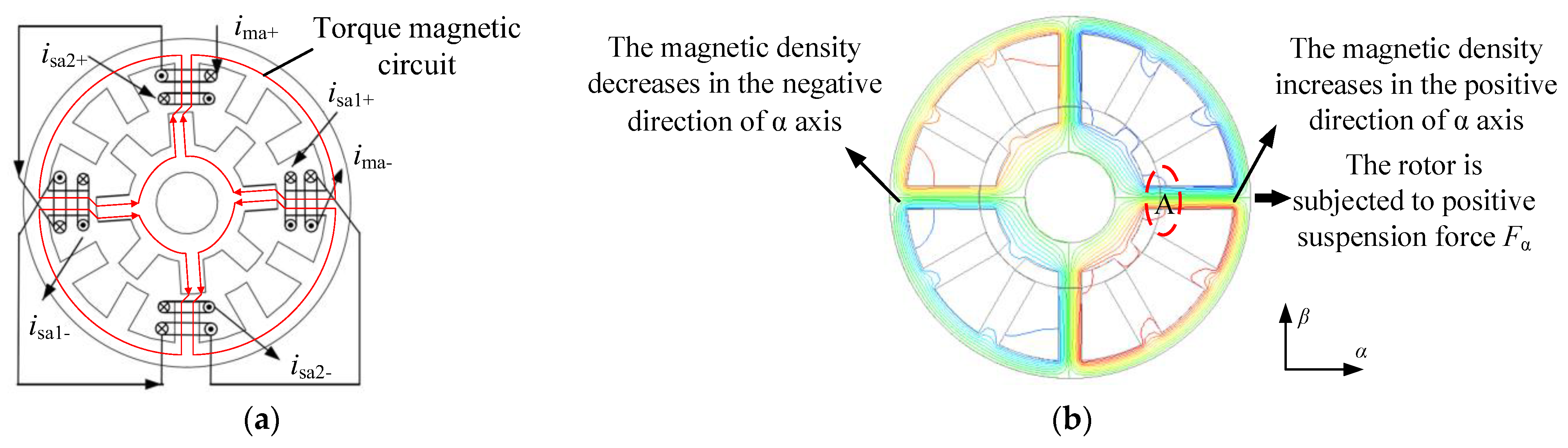
The core of the BSRM is made of a laminated silicon steel sheet. The torque generation follows the reluctance minimization principle, which means magnetic flux is always closed along the path of the least reluctance. As shown in Figure 1a, taking phase A as an example, when the main winding current ima is excited, the magnetic circuit is passed through the stator, air gap and rotor in turn to form a closed path. The magnetic field is distorted to generate electromagnetic force. The tangential electromagnetic force is used to produce torque, which rotates the rotor [9]. The rotor will rotate when three phases, A, B and C, are energized in turn. The suspension windings are energized with the current isa1 as shown in Figure 1a and generate a biased magnetic field to break the original magnetic field balance and generate radial force. The simulation results are shown in Figure 1b. The air gap magnetic field at the relative position of the rotor in the α direction changes. The magnetic density at A increases, generating the positive suspension force Fα of α direction. Similarly, radial force Fβ can be generated in the longitudinal direction (β direction) to ensure the radial suspension of the rotor.
2.2. Electromagnetic Characteristics Analysis of Torque and Suspension Force
When ima and isa1 in Figure 1a are energized, inductance matrix is deduced according to the equivalent magnetic circuit method. Then magnetic field energy storage W is obtained based on the principle of electromechanical energy conversion. The suspension force shown in Formula (1) can be obtained by using the virtual displacement method to compute the partial derivative of the magnetic field energy storage W with respect to the rotor displacement in α direction. Similarly, the suspension force in β direction can be obtained. The electromagnetic torque expression can be obtained by taking the partial derivative of magnetic field energy storage W with respect to rotor position angle θ, as shown in Formula (2) [10]:
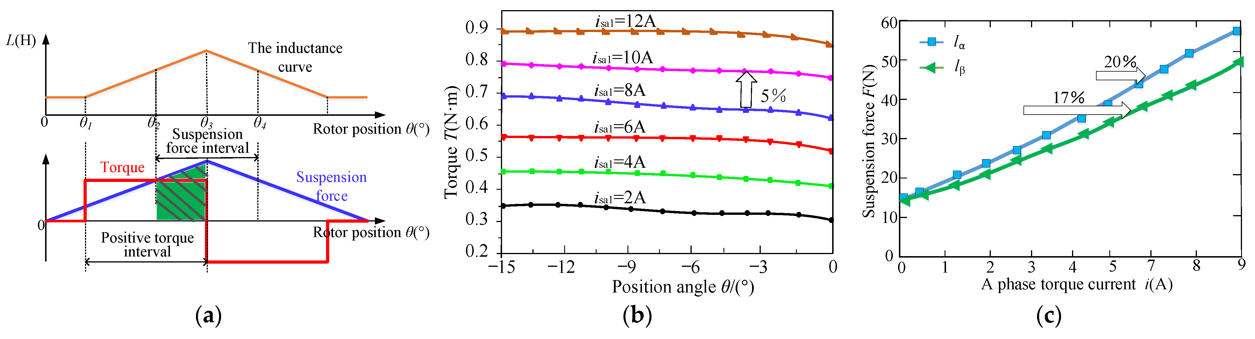
The isa2 is the suspension current in β direction. Jt(θ) and Kf(θ) are the functions with respect to motor structure parameters and rotor position angle θ. The rotor position angle θ is 0 deg when the stator teeth coincide with the rotor tooth center line. The conventional 12/8 BSRM inductance characteristic curve is shown in Figure 2a. It is noted that the positive torque generation range is from θ1 to θ3 when the suspension range is from θ2 to θ4. The overlap area of torque and suspension force is shaded in green. However, according to the conventional BSRM structure and operation principle shown in Figure 1, the overlap area of generating torque and radial force is narrow. The selection of a working point must compromise between the torque and radial force. Therefore, the region generating torque and radial force cannot be fully utilized, which may lead to the problem of small torque and insufficient suspension force. In this interval, the inductance of suspension winding changes with the position angle of the rotor. Therefore, the suspension winding will generate torque when energized. The torque current will also produce suspension force. In other words, there is coupling between torque and suspension force. Figure 2b shows the change curve of torque T when the main winding current of 12/8 BSRM ima is 10 A and the suspension winding current isa1 in the α direction takes different values. It is noted that when isa1 increases to 2 A, the torque increases by 0.1 N/m with a relative changing rate of 5%. Figure 2c shows the changing curves lα and lβ of the suspension force with the torque current when the suspension current is 1 A and the current of the A phase torque winding is from 1 A to 9 A. The changing rates dFα and dFβ of the suspension force with the torque current are 20% and 17%, respectively. As can be seen from the simulation results in Figure 2, there is coupling between suspension force and torque. Such strong coupling will directly lead to insufficient or unbalanced suspension force during the running of the motor. Furthermore, the torque output capacity is reduced and the control is complex. Therefore, the question of how to reduce the coupling between suspension windings has become the research direction of many scholars [11,12,13].
3. Magnetic Circuit Optimization Decoupling Strategy
Compared with the conventional BSRM, this optimization strategy improves the magnetic circuit by reconstructing the pole number of the stator and rotor and changing the polar arc and shape of the stator and rotor, which achieves the purpose of reducing the coupling between torque and suspension force. The loss of the motor is reduced, and operation efficiency is improved.
3.1. Hybrid Stator
3.1.1. Ordinary Hybrid Stator BSRM
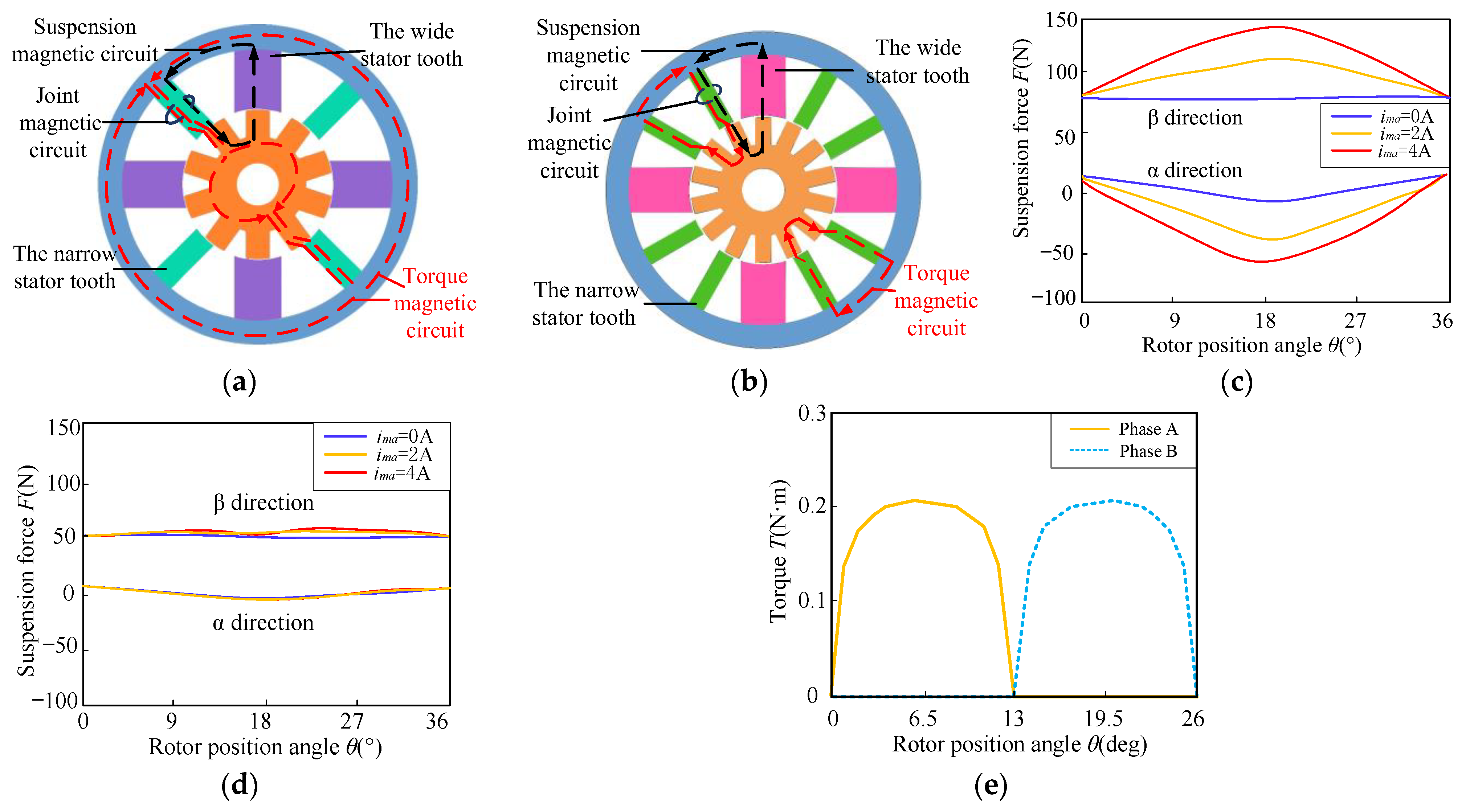
In light of the coupling between torque and suspension force, an 8/10 hybrid stator BSRM [14,15] (Appendix A) is proposed by Kyungsung University in South Korea. As shown in Figure 3a, wide stator teeth generate suspension force while narrow stator teeth generate torque, which means the torque and suspension pole are independent of each other. The windings on each pair of torque poles form a phase in series, while the windings on the four suspension poles are controlled independently. Due to advantages such as capability of independent control for each phase and three switching modes, an asymmetric converter is applied in the 8/10 hybrid stator BSRM. However, only four stator teeth generate torque in this structure, which are fewer than that of an ordinary BSRM generating torque. Therefore, the power density is low. Moreover, due to long magnetic circuit and few poles producing torque and suspension force, the torque current has a great influence on suspension force when the torque and suspension windings are excited simultaneously. To further improve motor performance, a 12/14 pole hybrid stator BSRM (Appendix A), the addition of the number of stator poles on the basis of the 8/10 pole hybrid stator BSRM is proposed in reference [16], as shown in Figure 3b. Compared with the 8/10 pole structure, the magnetic circuit is shortened in this structure, improving the power density. The core loss is effectively reduced, and the output torque is improved. Figure 3c,d, respectively, show the changing curves of suspension force F of the two hybrid stator tooth structures with the torque current ima. The suspension current isa is 2 A, and ima varies from 0 A to 2 A. It is noted from the two figures that ima of the 12/14 pole structure has little influence on F compared with that of the 8/10 structure. However, the power density is low, in that each stator tooth of the hybrid stator BSRM only generates torque or suspension force. In addition, the stator pole arc is the same as the rotor pole arc. The torque is very small or even zero during commutation due to the delay characteristics of current on the actual operation of the motor. The torque characteristic curve of the 12/14 pole BSRM is shown in Figure 3e. It is observed that there is a torque dead zone near the commutation position, which may lead to the disadvantages of large torque fluctuation. Since both motors are two-phase motors, the self-starting ability is weak.
3.1.2. Asymmetric Rotor Pole Hybrid Stator BSRM
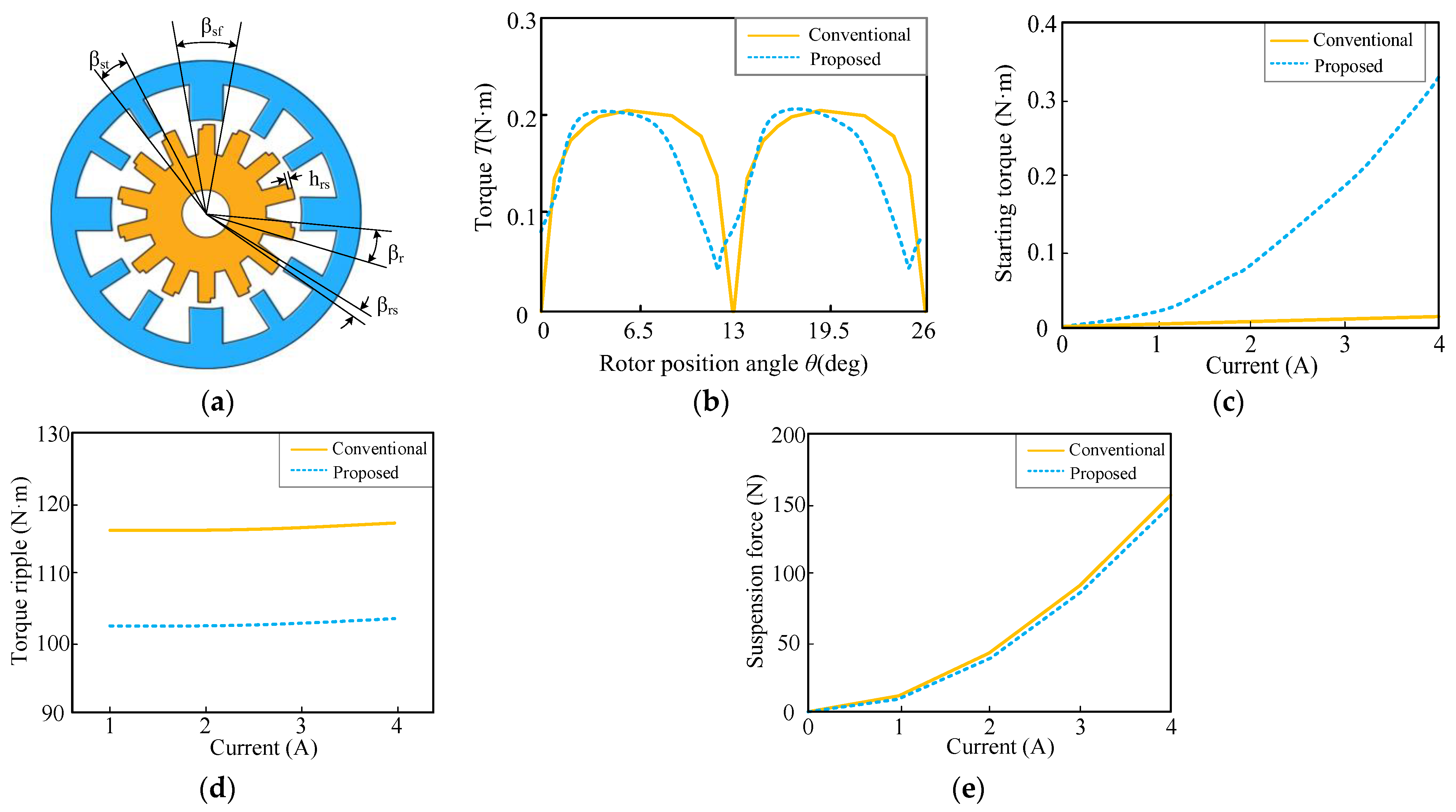
Due to the disadvantages of large torque fluctuation and weak self-starting ability of the conventional 12/14 BSRM, an asymmetric rotor pole hybrid stator BSRM (Appendix A) is proposed [17]. The only difference between a conventional 12/14 hybrid stator BSRM and the proposed structure is that the rotor pole surface of the proposed motor has a structure similar to a step. As shown in Figure 4a, βst is the pole arc of the torque pole, βsf is the pole arc of the suspension pole, βr is the pole arc of the asymmetric rotor pole, βrs is the step angle of the asymmetric rotor pole and hrs is the step height of the asymmetric rotor pole. Reference [17] finally concludes that the combination of βst = 11°, βr = 14° and βrs = 3° is the best, which means motor has smaller torque ripples and higher starting torque and average torque. Figure 4b–e show torque characteristics, starting torque, torque ripple and suspension force in conventional and proposed hybrid stator BSRMs. The proposed motor eliminates the torque dead zone, produces positive torque at any rotor position, improves the starting torque of the motor and reduces torque ripple. However, due to the asymmetric rotor pole, the average suspension force is slightly reduced compared with the conventional one.
3.1.3. Permanent Magnet Biased Hybrid Stator BSRM
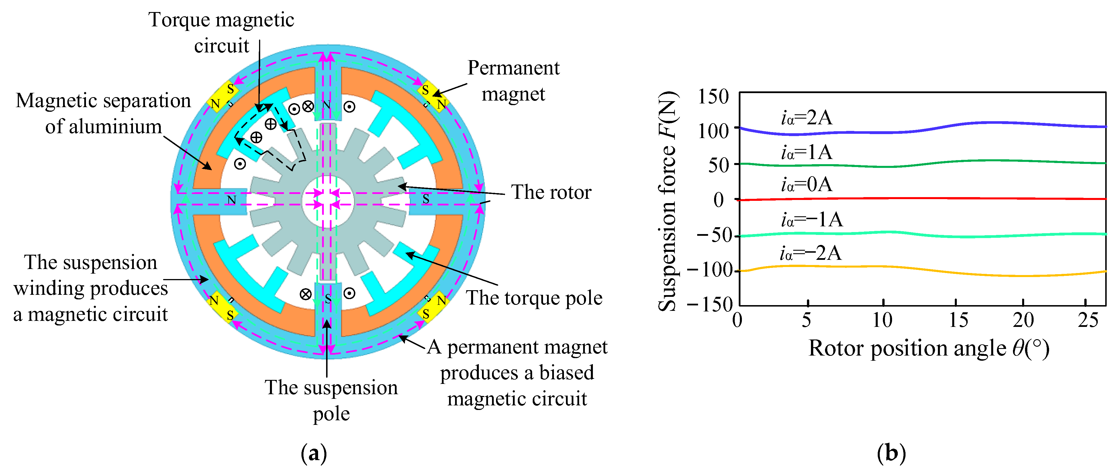
The coupling cannot be completely eliminated due to the existence of a common magnetic circuit of the hybrid stator tooth BSRM torque system and suspension system. Researchers proposed a strategy to separate the torque magnetic circuit from the suspension magnetic circuit with magnetic isolation materials. The suspension force is increased by permanent magnets, providing a biased magnetic field [18,19,20,21,22]. As shown in Figure 5a, the structure (Appendix A) is evenly embedded with four permanent magnets (yellow area in the figure) along the stator circumference to produce the biased flux, which is superimposed with the magnetic field generated by the suspension winding to generate suspension force. The purple dotted line is the biased magnetic flux path in the figure. The green dotted line is the suspension magnetic flux path generated when the suspension winding is excited. The black dotted line is the torque magnetic flux path. It is noted that the torque magnetic circuit and the suspension magnetic circuit are independent from each other. Figure 5b shows the suspension force curves when the suspension windings in α direction are energized with different iα. It is observed that the force generated by the current with the same size and different directions is the same size in different directions. For example, when iα is 1 A and iα is -1 A, the Fα is 50 N in different directions. Beyond that, the force is almost constant, which is beneficial to the stable suspension of the motor. Magnetic isolation aluminum is added into the stator yoke to make the torque magnetic field independent of the suspension magnetic field, realizing the self-decoupling of suspension force and torque. At the same time, a secondary air gap is designed to prevent the permanent magnet from short-circuiting and provide a path for the suspended flux. However, the size of the permanent magnet in the stator has a great influence on the biased flux. It is difficult to accurately grasp the precision of the permanent magnet size in actual manufacturing. A permanent magnet biased hybrid stator BSRM has large torque fluctuation and weak self-starting ability because it only has two phases.
3.1.4. Axially Magnetized Four Degrees of Freedom BSRM
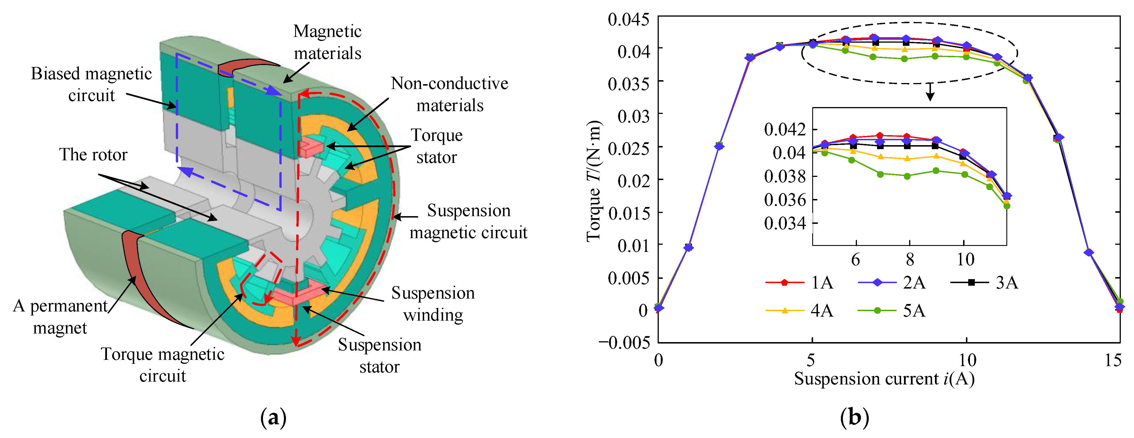
In actual operation of the motor, the rotor offset direction is arbitrary. In order to improve the suspension performance of the motor, a four degrees of freedom (4-DOF) of a suspension BSRM is proposed. The structure consists of two motors, each of which has two radial control degrees of freedom. Four degrees of freedom of suspension is realized while achieving decoupling. Reference [23] proposes a double 12/12 pole BSRM (Appendix A). Each motor has a 12/12 pole structure and also adopts a hybrid stator tooth structure. A permanent magnet is inserted between the two motors to separate them. The permanent magnet generates an axial biased flux. The motor topology is shown in Figure 6a. The two 12/12 pole structure BSRMs are on the left and right sides of the permanent magnet. The two opposite windings on the wide stator teeth of each motor are connected in series to form a set of suspension windings, which act together with the biased flux generated by the permanent magnet to realize 4-DOF suspension of the motor. Like a permanent magnet biased hybrid stator BSRM, the stator is embedded with magnetic isolation materials to separate the torque poles from the suspension poles to realize the independence of the torque magnetic circuit and the suspension magnetic circuit. In order to improve the self-starting ability of the motor, the two rotors of the motor are not completely coincident in axial direction, making the two inductance rising regions have overlapping parts. Therefore, only a small voltage is needed on a torque winding to move the rotor into an aligned position. Then a voltage is applied to another motor torque winding to make the rotor rotate.
Figure 6b shows the changing curve of BSRM torque T with the suspension current i of this structure. It is observed that when i changes between 1A and 5A, the variation region of T is from 0.039 to 0.0413 N/m. The maximum relative error is about 5.56%, which is within the error range. Therefore, the mutual effects between torque control and suspension control is almost ignored, indicating that the motor in this structure can realize natural decoupling between the torque and suspension force.
In order to reduce the coupling of the BSRM itself, the above strategy adopts a special structure design for the motor itself. The hybrid stator teeth reduce the coupling between torque and suspension force while one-phase-wide stator teeth must be sacrificed to generate suspension force, resulting in few teeth to generate torque. The output capacity of torque is weakened and the motor can only be used as a two-phase motor. Therefore, the motor has poor self-starting ability and low power density. Additionally, the number of rotor poles is larger than that of stator poles. The motor has poor high-speed adaptability.
3.2. Double Stator BSRM
Considering the deficiency of the hybrid stator tooth structure BSRM, a decoupling strategy of a double stator BSRM (DSBSRM) (Appendix A) is proposed [24]. This structure adopts a three-phase operation system. Torque and torque magnetic circuits are provided by the outer stator, the principle of which is the same as that of a conventional SRM. However, suspension force is provided by the inner stator. The independent windings on the inner stator pole are controlled to output suspension force.
3.2.1. Conventional DSBSRM
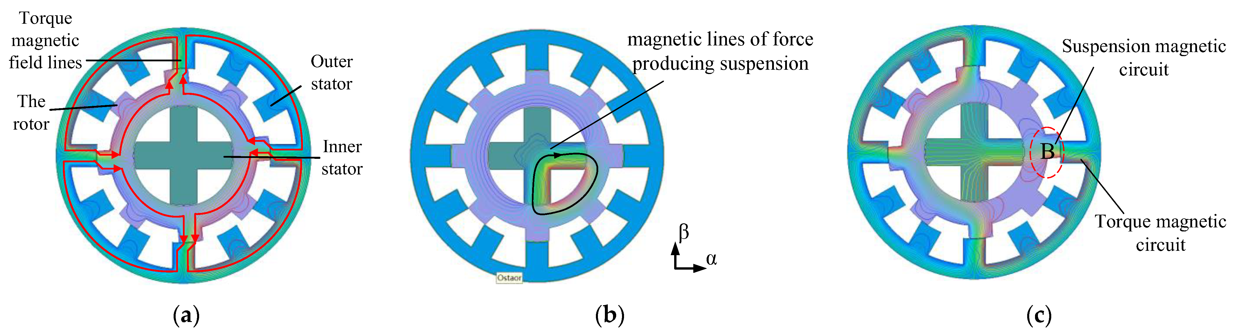
Figure 7a shows the magnetic line of force when phase A of the outer stator is energized. Figure 7b shows the magnetic line of force when the suspension winding in +α and −β direction of the inner stator is energized. Theoretical analysis shows that the design realizes the fundamental decoupling between torque and suspension force in the structure.
Nevertheless, according to the finite element simulation results, when the torque windings of phase A and the suspension windings in +α direction are energized at the same time, the generated magnetic flux paths are not completely independent of each other. As shown in Figure 7c, the magnetic force lines generated by the torque and suspension force are interwoven when the torque and suspension windings are excited simultaneously. Therefore, the torque and suspension force affect each other, and the decoupling of this structure is not completely realized.
3.2.2. Segmental Rotor Type 12/8 DSBSRM
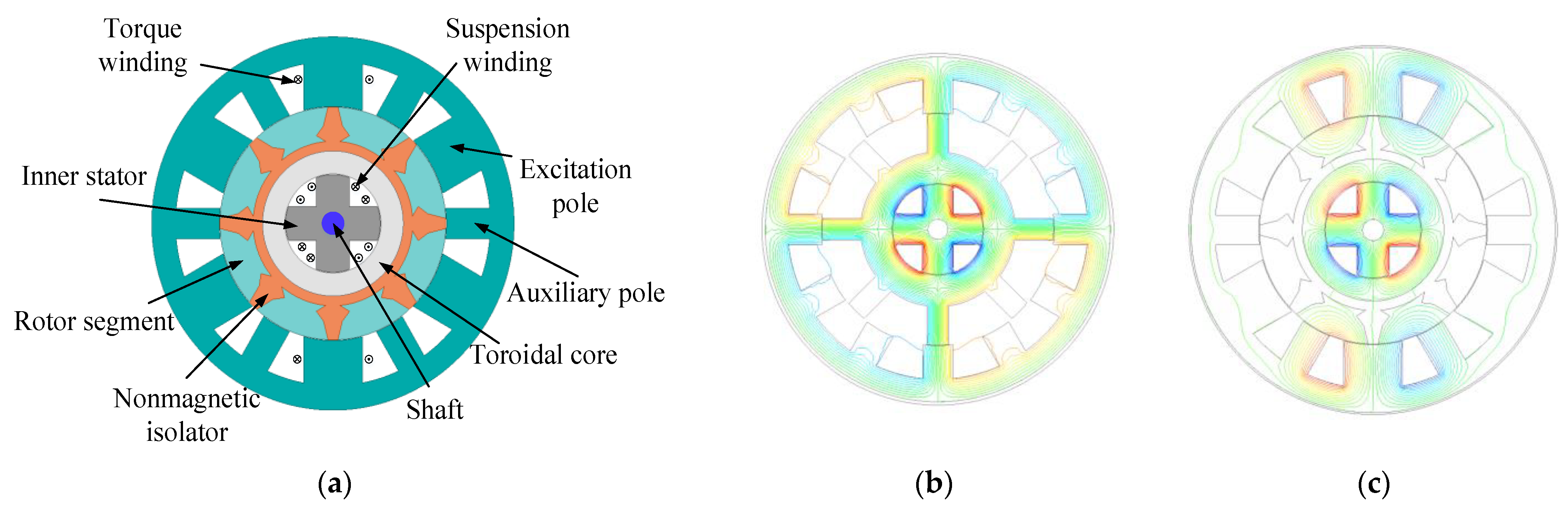
On the basis of the above conventional DSBSRM, a structure of a segmental rotor type 12/8 DSBSRM (Appendix A) [25] is proposed as shown in Figure 8a. The outer stator of the proposed structure is divided into two magnetic poles: excitation and auxiliary magnetic poles. Torque is produced by the torque windings, which wind around the excitation magnetic poles. The rotor is adopted as a non-salient structure and the nonmagnetic isolator is employed to achieve independence between torque and the suspension system. The suspension mechanism of the proposed DSBSRM is the same as that of a conventional DSBSRM. Figure 8b,c show magnetic flux distribution of a conventional 12/8 DSBSRM and segmental rotor type 12/8 DSBSRM, respectively, when phase A and all suspension windings are excited simultaneously. It is observed that the magnetic flux generated by torque and suspension winding passes the same rotor yoke in a conventional 12/8 DSBSRM, while the magnetic flux generated by torque and suspension windings is independent from each other because of the nonmagnetic isolator in the segmental rotor type 12/8 DSBSRM. Therefore, the proposed structure reduces the coupling between torque and suspension force and improves the output torque density compared with that of a conventional 12/8 DSBSRM.
3.2.3. Axial Magnetizing Hybrid Excitation DSBSRM
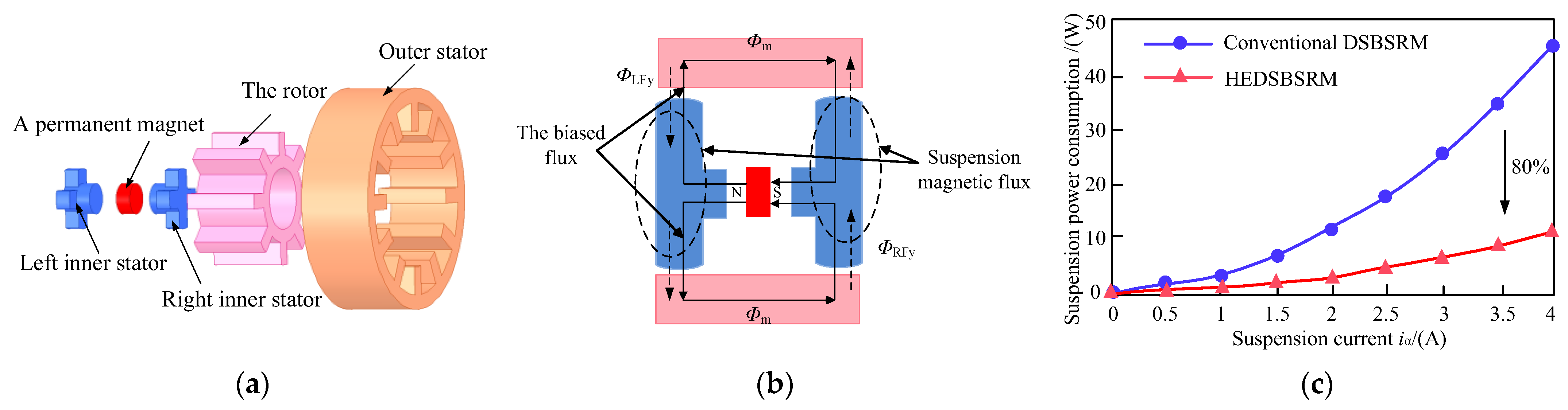
Due to the small size of inner stators and weak suspension carrying capacity of the above common double stator BSRM, researchers propose an axial magnetizing hybrid excitation double stator bearingless switched reluctance motor (HEDSBSRM) [26] (Appendix A). Figure 9a shows the topology of the motor. Compared with a conventional double stator BSRM, there are two inner stators in the proposed motor. Permanent magnet rings are added between the two inner stators to provide a biased magnetic field. The direction of the biased magnetic field generated is axial. The two inner stators are embedded with suspension windings. The magnetic field generated by the suspension windings and the magnetic field generated by the permanent magnet generate suspension force jointly. Figure 9b describes the biased magnetic circuit provided by the permanent magnet of the proposed motor and the suspension magnetic circuit provided by the suspension windings. Among them, the biased flux Φm is produced by the middle permanent magnet. The suspension flux ΦLFx is generated by the left inner stator suspension winding. The suspension flux ΦRFy is generated by the right inner stator suspension winding. The suspension force required by the operation of the motor is produced by the biased flux and the suspension flux jointly.
Figure 9c shows the comparison of suspension power consumption of the two motors. It is observed that when iα changes from 0 A to 4 A, the average suspension power consumption of HDSBSRM is reduced by 80% compared with that of a conventional DSBSRM. This HEDSBSRM effectively reduces suspension power consumption due to permanent magnets providing a biased magnetic field.
3.2.4. Novel Hybrid Excitation DSBSRM
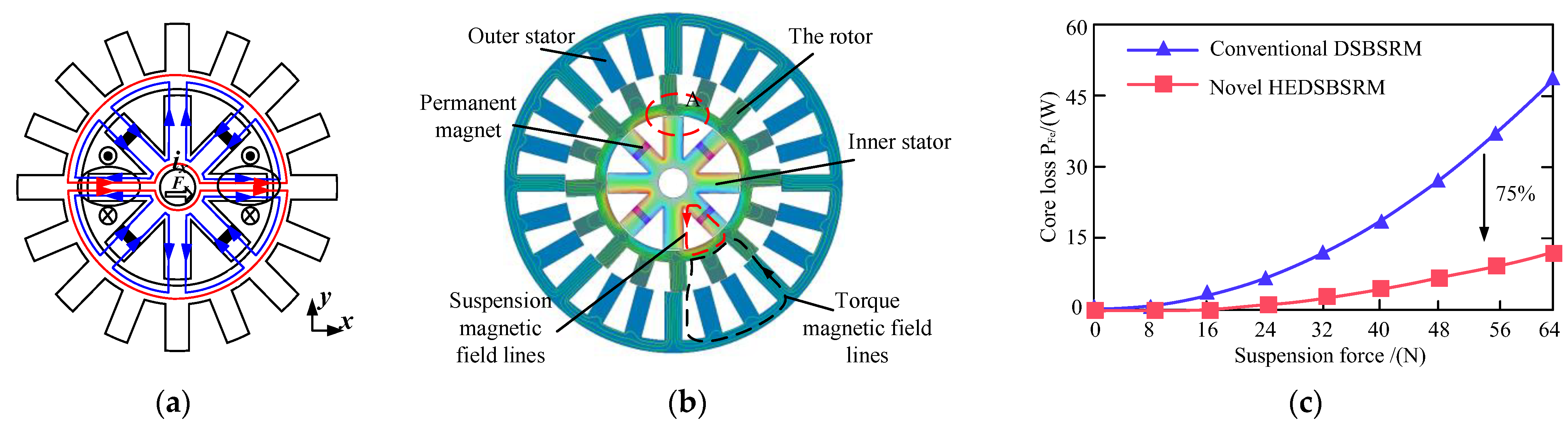
Although the double stator axial magnetization structure strengthens the suspension of the motor, the axial length of the motor increases, resulting in a low critical speed of the motor and a complex suspension control system. On the basis of the above double stator, reference [27,28] propose a novel hybrid excitation dual stator BSRM (HEDSBSRM) (Appendix A). Compared with the common double stator structure, the permanent magnet is nested in the inner stator on the basis of increasing the stator poles. As shown in Figure 10a, the suspension force is generated jointly by the inner stator permanent magnet and suspension windings. Stable suspension is realized by controlling the current of the suspension windings. Figure 10b shows the magnetic force line path when the torque and suspension windings of phase A are energized at the same time. It is noted in Figure 10a that the torque magnetic circuit and suspension magnetic circuit are independent from each other, indicating that this structure realizes the decoupling fundamentally. Figure 10c shows the comparison of core loss under the same suspension force output of the two motors. It is observed that the core loss of the novel HEDSBSRM is smaller than that of the conventional DSBSRM. Especially when the suspension force is 64N, the core loss of the novel HEDSBSRM is reduced by about 75% than that of conventional DSBSRM. In conclusion, the magnetic circuit is shorter and the core loss is smaller compared with a conventional DSBSRM. However, the rotor speed is difficult to be improved upon due to excessive stator and rotor poles.
3.3. Wide Rotor BSRM
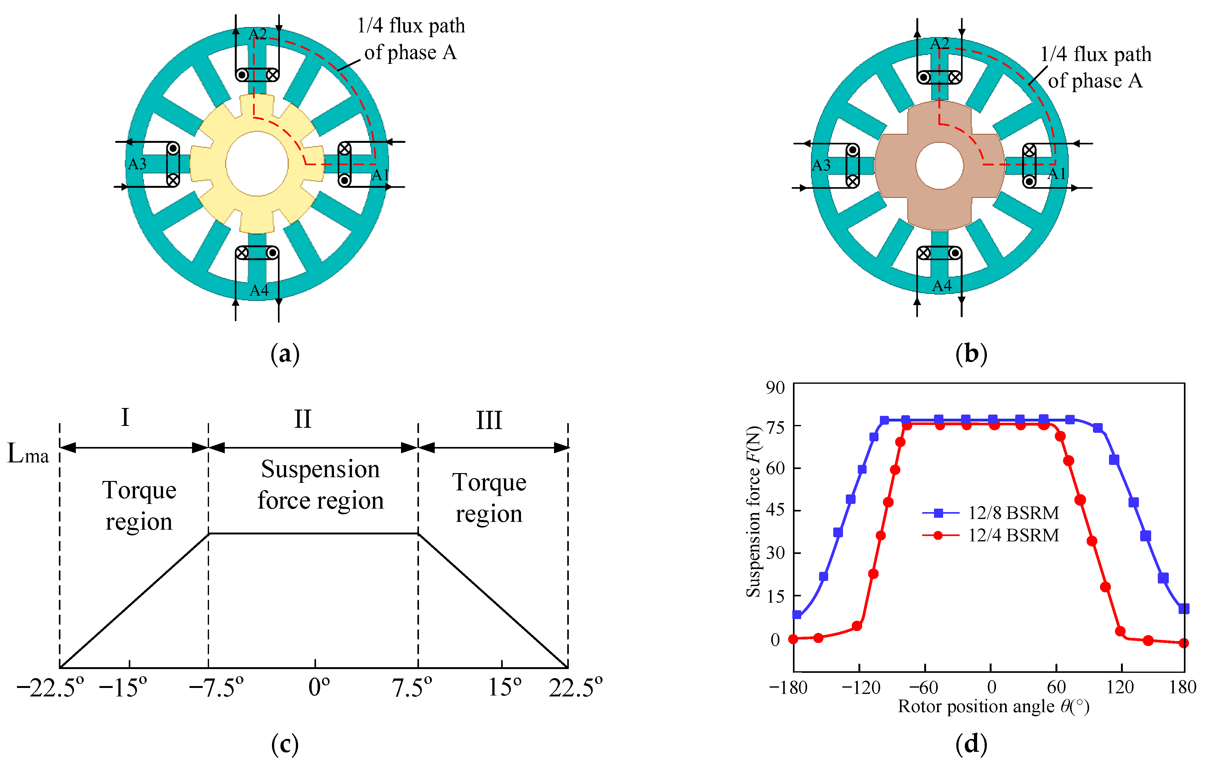
The above structure reduces coupling by optimizing the magnetic circuit. In addition, researchers propose a wide rotor BSRM, which realizes decoupling by improving the magnetic circuit and enhancing the inductance overlap region. The torque and suspension force principle of the structure are the same as that of an ordinary 12/8 BSRM. The magnetic flux path is also similar. That said, the rotor teeth are wider than the stator teeth, which improves the overlap area of stator and rotor poles and the winding inductance changing curve, making the flat top region appear when the inductance is at maximum.
As shown in region II of Figure 11c, this wide rotor structure can give full play to its decoupling efficiency when adopting the dual-phase conduction strategy. It means that torque and suspension force are generated in different regions: the inductance is unchanged in the flat top region of the inductance. The excitation is applied to provide suspension force. At this time, the suspension winding has no effect on the torque. The torque is provided in the inductance changing region I and III, realizing decoupling. In addition, due to the ratio of the suspension force to the input current is the largest in the flat top region of the inductance, the output efficiency of suspension force is high, and it is beneficial to reduce the suspending power consumption. References [29,30] propose a 12/8 wide rotor structure BSRM (Appendix A). The proposed BSRM is added to the rotor pole arc on the basis of the conventional 12/8 pole. The winding connection of the proposed motor is the same as that of the conventional single-winding BSRM, as shown in Figure 11a. Reference [31] proposes a single-winding 12/4 pole wide rotor structure BSRM (Appendix A), reducing the rotor poles on the basis of a 12/8 pole, as shown in Figure 11b. Due to only four rotor poles, the rotor teeth of the proposed BSRM are wider than the stator teeth. Therefore, the flat top region of inductance is larger, realizing the control of torque and suspension force in different areas. Figure 11d shows the changing curves of suspension force F in the α direction of two wide rotor teeth BSRMs. It is noted that the suspension force generated by the 12/8 pole structure has a wider region. Reference [32] also shows that a 12/8 pole has better torque characteristics than a 12/4 pole. But the rotor with the 12/4 pole structure has few poles and is more suitable for high-speed operation. Since the rotor teeth are larger than the stator teeth, the wide rotor teeth BSRM can compensate for the weak self-starting ability of the hybrid stator teeth BSRM and is easy to process and assemble. However, the wide rotor teeth compress the inductance rise interval, and the effective torque interval is reduced accordingly.
3.4. Co-Suspension Winding BSRM
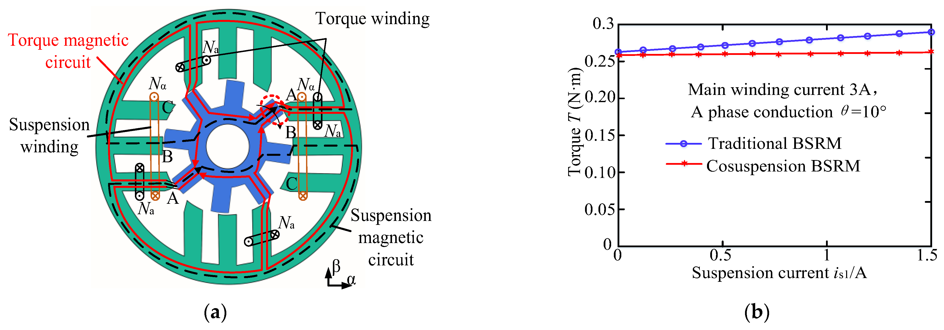
The stator of a conventional 12/8 dual-winding BSRM has both torque windings and suspension windings. The suspension windings, which are also known as control windings, are divided into A, B and C three-phase windings. There is one set in α and β direction of each phase. A total of six sets of control windings are required. Therefore, another six sets of control windings are required to generate radial force besides the alternating conduction of three-phase torque windings when the motor is running. Hence, six sets of transistors are needed to switch to control radial force. Moreover, the control windings increase with the increase of phase number, making the control system more complex. References [33,34] propose a co-suspension winding BSRM (Appendix A). The torque winding of the proposed structure is the same as that of a conventional BSRM. However, only two sets of control windings that generate radial force are required.
Figure 12a is the schematic diagram of a magnetic circuit when the main winding of A phase of the motor is on and the suspension winding in the direction of α is energized. There is one co-winding winding around the three poles of phases A, B and C. The two opposite groups of winding are connected in series to form the control winding in direction α (the yellow winding in the figure). Direction β has the same series. The red solid lines are the lines of magnetic force generated by the main windings. The black dotted lines are the lines of magnetic force generated by the suspension windings. The main and suspension windings of phase A in the positive direction of α generate a magnetic field simultaneously, and the magnetic field direction is the same in the positive direction. Thus, the air gap flux at pole A in the positive direction of α is enhanced, generating radial force in the positive direction of α. Therefore, the proposed three-phase motor only needs two sets of windings in α and β direction to control suspension. When the motor is running, the three-phase torque windings switch to generate torque. The control windings do not need to move but adjust the current of two sets of control windings according to the position of the rotor to realize rotor suspension, which means just two groups of transistors are required to achieve the motor suspension control. The amount of control windings does not change with the motor phase number. The transistors of the control circuit are reduced to 1/3 of the original. The control circuit is simplified, and the algorithm is easy to write. Figure 12b shows the comparison curve of the influence of suspension winding current is1 of a conventional motor and co-suspension structure motor on the torque T when phase A is on. The torque winding current is a constant 3A. The is1 varies from 0 to 1.5A. It is noted that the influence of is1 on static torque is relatively small, while the torque of the conventional structure increases slightly with the increase of current of control winding. In conclusion, the co-suspension winding BSRM simplifies the complexity of control while realizing decoupling. However, the different stator shape of this motor results in unbalanced torque of each phase and large torque pulsation.
3.5. Composite Structure BSRM
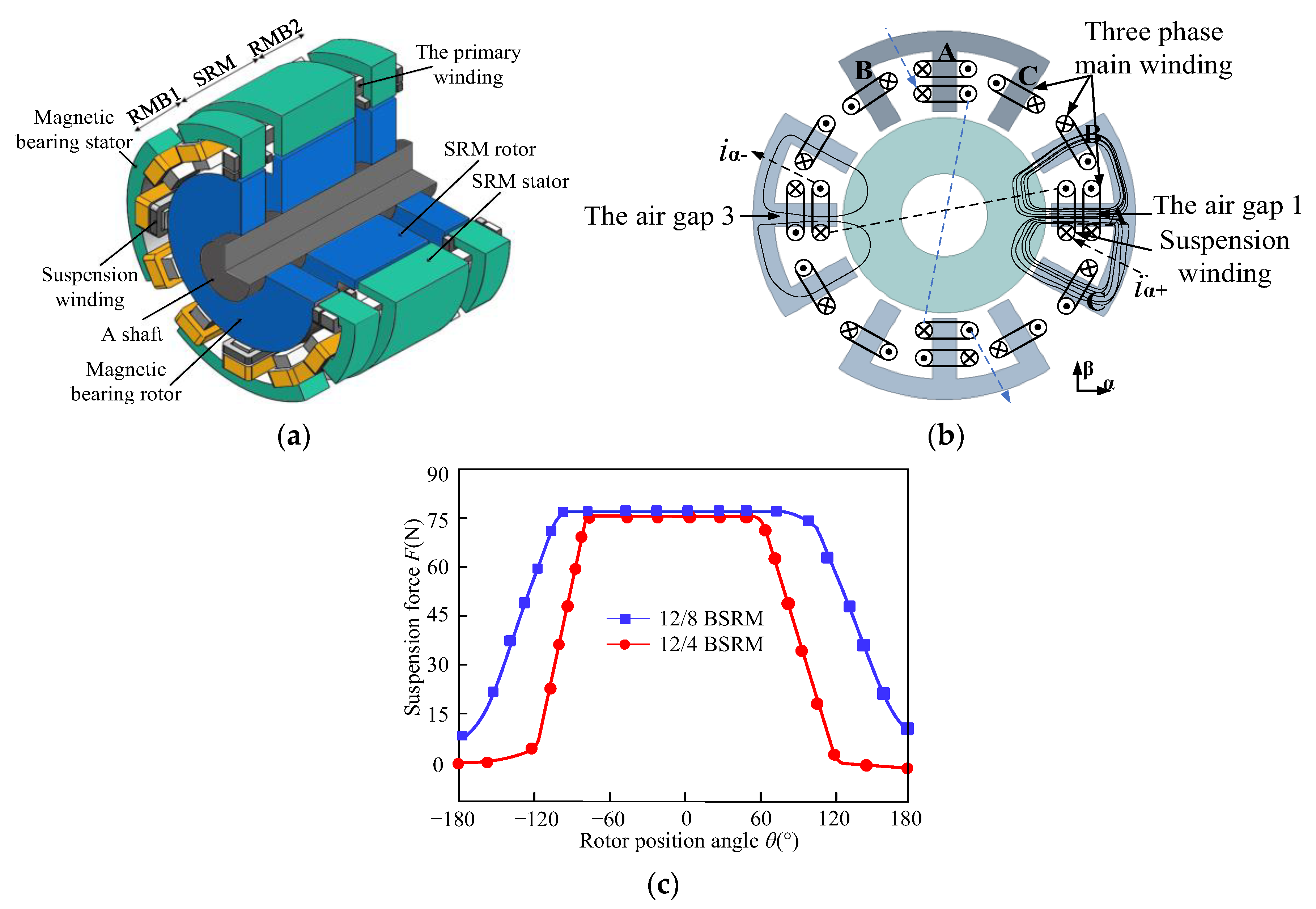
Since BSRMs have combined characteristics of magnetic bearings and switched reluctance motors, reference [35] proposes a co-winding composite structure BSRM (Appendix A) that combines two stator block radial magnetic bearings (RMB) and a 12/8 pole switched reluctance motor (SRM). The proposed motor can realize 4-DOF suspension control, which is the same with axially magnetized four degrees of freedom BSRM.
Figure 13a shows this motor’s topology. Each winding passes through two stators of radial magnetic bearing (RMB1, RMB2) and one SRM stator. That means stators of three motors share a same winding which is divided into three phases. Each phase winding is separated by 90° in series to form the main winding of this phase. The middle stator teeth of each block stator are wrapped with suspension windings, and the two relative suspension windings are connected in series to form a set of suspension windings to control motor suspension. The torque generation principle of this motor is similar to an SRM. Three-phase windings A, B and C are energized in turn to generate torque for the motor rotating. At this time, the magnetic field generated by the torque windings is a biased magnetic field for RMB. Further, suspension force is generated by the suspension windings, which are jointly generated by biased magnetic field and suspension magnetic field. Figure 13b takes RMB1 as an example to illustrate the mechanism of suspension force generation. When iα is introduced in the positive direction of α, the magnetic field of the main winding and suspension winding are superimposed. Thus, the magnetic field of air gap 1 is enhanced and the magnetic field of air gap 3 is weakened, resulting in radial force Fα in the positive direction of α. Fβ is similar to that. By changing the iα in two directions, the suspension force required by the motor can be generated to realize 4-DOF suspension of the rotor. Although the structure realizes the decoupling of torque and suspension force because of non-interfering torque and a suspension magnetic circuit, the coupling relationship between the suspension force still exists because of its unique structure. Figure 13c shows the magnitude of Fβ when iα in α direction changes under excitation of different phases. When the suspension current in β direction iβ is 0A, Fβ does not change with iα when phase A conducts alone. However, Fβ changes linearly with iα when phase B or phase C are conducting separately, which is due to the asymmetrical distribution with respect to α and β of biased flux when the other two phases are conducting separately. The analysis shows that this composite structure BSRM has a coupling relationship between the interplay of suspension forces in different directions. Therefore, the winding structure is improved by adopting a double winding structure on each RMB and SRM on this basis to reduce the coupling between suspension forces [35].
4. Future Research Direction of BSRM
Generally speaking, the BSRM has obvious advantages in industry, flywheel energy storage, aerospace and other fields that require high comprehensive performance of motors, due to its advantages of low fault tolerance, low loss and high power density. Based on the above discussion in methods of improving BSRM performance, the BSRM has great potential in future theoretical research and practical applications. BSRMs have a variety of topological structures. Compared with conventional SRMs, the BSRM has a long way to go in commercial application and industrialization due to the integration of double salient poles and torque suspension. Meanwhile, requirements of different application fields also pose different challenges to BSRM performance. The key research direction of BSRMs in the future should be carried out from the following aspects:
- Derivative of novel topologies: New structures such as block stator and double stator hybrid excitation make the electromagnetic performance of BSRMs more excellent. However, there is more room for improvement, obviously. Better topology design can further improve the power density and suspension performance and reduce iron loss, making the electromagnetic performance of the BSRM superior. Therefore, BSRM topology is still a hot spot for future research [36,37,38,39,40,41,42,43,44,45].
- Multi-objective global optimization: The BSRM optimization objective is determined by its application occasions. There are often multiple optimization objectives in a specific occasion. Each performance index is mutually constrained. Therefore, exploring ways to optimize BSRM power density, efficiency and other comprehensive performance indicators is a significant direction of BSRM research in the future [46].
- Fault tolerance design and control technology: When the motor is running, phase deficiency, winding short circuit, open circuit and other faults may exist, making torque and suspension force uncontrollable. Therefore, the study of fault tolerance technology is inevitable, such as establishing short-circuit or open-circuit suspension compensation models, etc. In addition, the selection of an appropriate control strategy can also improve the fault tolerance of a motor and effectively reduce the torque and suspension force pulsation and improve the control accuracy [47,48,49].
- Ameliorate eccentric effect: The rotor decentration of a BSRM is caused by no mechanical bearing support of the BSRM, technological error during manufacturing and the element of gravity and centrifugal force during motor operation. Decentration will produce unbalanced magnetic pulling force, which leads to noise and vibration of the motor and other phenomena affecting motor performance. Therefore, exploring ways to reduce the influence of decentration on motor performance and improve motor stability is the focus of future research [50,51,52].
5. Conclusions
Based on the analysis of the operation mechanism of BSRMs, this paper first analyzes the root of the coupling between the torque and suspension force and summarizes existing strategies for decoupling and improving motor performance from the motor structure. Secondly, the structures of stator and rotor are altered to transform the magnetic circuit to realize the decoupling of torque and suspension force. Different topology structures are derived by each structure. The motor performance is improved while coupling is reduced. Finally, the future research direction of BSRMs is proposed. In conclusion, BSRM has superiority in the high efficiency, high power density and high reliability dependence of motor applications. However, the existing research is not mature enough to fully meet the needs of modern equipment. It is firmly believed that researchers will conduct in-depth research on BSRM technology to achieve breakthroughs in the future.
Author Contributions
Q.X. pointed out the direction of the framework and content of the paper and drafted the manuscript; Y.O. understood and summarized the single stator BSRM; Z.P. studied and summarized the double stator BSRM; Y.S. made the prospect and prediction for the future development of BSRM. All authors have read and agreed to the published version of the manuscript.
Funding
This work was supported by the Key Research and Development Program of Jiangsu Province (BE2021094).
Data Availability Statement
The data supporting this review are available from the corresponding authors upon request.
Conflicts of Interest
The authors declare no conflict of interest.
Appendix A
| Motors | Advantages | Disadvantages | Parameters | Value | Motors | Advantages | Disadvantages | Parameters | Value |
 8/10 hybrid stator tooth BSRM | The torque and suspension pole are independent of each other | Long magnetic circuit | Outer diameter of stator(mm): | 112 |  Axially magnetized DSBSRM | Improving the suspension efficiency | Low critical speed and complex suspension control system | Outer/inner diameter of outer stator(mm): | 129/73 |
| Inner diameter of stator(mm): | 62 | Outer/inner diameter of rotor(mm): | 72/40 | ||||||
| Yoke thickness of Stator(mm): | 10 | Outer/diameter of inner stator(mm): | 39/19 | ||||||
| Inner diameter of rotor(mm): | 18 | Thickness of permanent magnet(mm): | 2 | ||||||
| Pole arc of stator for torque(deg): | 18 | Diameter of permanent magnet(mm): | 19 | ||||||
| Pole arc of stator for radial force(deg): | 36 | Yoke thickness of outer stator/rotor(mm): | 8/8 | ||||||
| Pole arc of rotor (deg): | 18 | Yoke thickness of inner stator(mm): | 9.5 | ||||||
| Large torque fluctuation and weak self-starting ability | Length of axial stack(mm): | 40 | |||||||
 12/14 hybrid stator tooth BSRM | Short magnetic circuit and low core loss | Outer diameter of stator(mm): | 112 |  Hybrid excitation DSBSRM | Improving suspension force and shortening magnetic circuit | Difficult to improve the rotor speed | Outer diameter of outer stator(mm): | 113 | |
| Inner diameter of stator(mm): | 60.2 | Inner diameter of outer stator(mm): | 72.6 | ||||||
| Yoke thickness of stator(mm): | 7.7 | Outer diameter of inner stator(mm): | 42.2 | ||||||
| Yoke thickness of rator(mm): | 9.7 | Yoke thickness of outer stator(mm): | 4.6 | ||||||
| Pole arc of stator for torque(deg): | 11 | Yoke thickness of rotor(mm): | 4.8 | ||||||
| Pole arc of stator for radial force(deg): | 25.7 | Outer diameter of rotor(mm): | 72 | ||||||
| Pole arc of rotor (deg): | 14 | Pole arc of outer stator/rotor(deg): | 7.5/7.5 | ||||||
| Length of axial stack(mm): | 40 | Length of axial stack(mm): | 37.5 | ||||||
| Rotor tooth height(mm): | 9.8 | ||||||||
 Permanent magnet biased hybrid stator BSRM | Self-decoupling of suspension force and torque | Outer diameter of suspending pole(mm): | 132 |  Double stator BSRM | Small torque fluctuation | Not realizing decoupling | Torque stator outer diameter (mm): | 153 | |
| Inner diameter of suspending pole(mm): | 56.6 | Radial force stator outer diameter (mm): | 59.4 | ||||||
| Outside diameter of torque pole(mm): | 108 | Rotor outer diameter (mm): | 102.6 | ||||||
| Permanent magnet width(mm): | 10 | Pole arc of stator for torque(deg): | 15 | ||||||
| Permanent magnet height(mm): | 6.6 | Pole arc of stator for radial force(deg): | 32 | ||||||
| Pole arc of rotor (deg): | 16 | ||||||||
| Yoke thickness of rotor(mm): | 9 | Length of axial stack(mm): | 40 | ||||||
| Shaft diameter (mm): | 17 | ||||||||
 12/8 pole wide rotor BSRM | Low suspension power consumption | compressing the inductance rise interval and reducing the effective torque interval | Stator diameter(mm): | 97 | |||||
| Pole arc of stator for torque(deg): | 12 | Yoke thickness of stator(mm): | 6.1 | ||||||
| Yoke thickness of rotor(mm): | 7.65 | ||||||||
| Pole arc of stator for radial force(deg): | 25 | Length of stator stack(mm): | 51 | ||||||
| Pole arc of stator(deg): | 15 | ||||||||
| Difficult to design the permanent magnet size | Good self-starting ability | Pole arc of rotor(deg): | 30 | ||||||
| Pole arc of rotor (deg): | 13 | Diameter of axle(mm): | 20 | ||||||
| Rotor tooth height(mm): | 7 | ||||||||
| Length of axial stack(mm): | 45 | Stator tooth height(mm): | 16.5 | ||||||
 Axially magnetized four degrees of freedom BSRM | Decoupling of torque and suspension force and 4 degrees of freedom of suspension | Poor self-starting ability and low power density | Pole arc of stator for radial force(deg): | 30 |  12/8 pole wide rotor BSRM | Outer diameter of stator (mm): | 115 | ||
| Pole arc of stator for torque(deg): | 15 | More suitable for high-speed operation | Outer diameter of rotor (mm): | 59.7 | |||||
| Pole arc of stator (deg): | 15 | ||||||||
| Pole arc of rotor(deg): | 15 | Pole arc of rotor (deg): | 45 | ||||||
| Length of axial stack(mm): | 48 | ||||||||
 Composite structure BSRM | Coupling between the suspension force | SRM/RMB: Outer diameter of stator(mm): | 100 |  Co-suspension winding BSRM | Simplifying control and realizing decoupling | Large torque pulsation | Outer diameter of stator (mm): | 175 | |
| Outer diameter of rotor(mm): | 49.3 | Outer diameter of rotor (mm): | 97 | ||||||
| Diameter of axle(mm): | 20 | Length of axial stack(mm): | 100 | ||||||
| Pole arc of stator(deg): | 15 | ||||||||
| Yoke thickness of stator(mm): | 6.5 | Inner diameter of stator (mm): | 98 | ||||||
| SRM: Length of axial stack(mm): | 45 | ||||||||
| Yoke thickness of rotor(mm): | 7 | Inner diameter of rotor (mm): | 60 | ||||||
| Pole arc of rotor(deg): | 15 | ||||||||
| RMB: Yoke thickness of rotor(mm): | 14.65 | Pole arc of stator/rotor (deg): | 15/15 | ||||||
| Length of axial stack(mm): | 20 | Yoke thickness of stator/rotor(mm): | 15/15 | ||||||
 Asymmetric rotor pole hybrid stator BSRM | Improving the starting torque of the motor and reducing torque ripple | Reducing average suspension force | Outer diameter of stator(mm): | 112 |  Segmental rotor type 12/8 DSBSRM | Decoupling between torque and suspension force and improving the output torque density | Outer diameter of outer stator(mm): | 153 | |
| Inner diameter of stator(mm): | 60.2 | Outer diameter of rotor(mm): | 95.4 | ||||||
| Yoke thickness of stator(mm): | 7.7 | Thickness of rotor segment(mm): | 8 | ||||||
| Yoke thickness of rotor(mm): | 9.7 | Thickness of toroidal core(mm): | 9.4 | ||||||
| Pole arc of stator for torque(deg): | 11 | Thickness of nonmagnetic isolator(mm): | 4 | ||||||
| Pole arc of stator for radial force(deg): | 25.7 | Pole arc of outer stator (deg): | 30/10 | ||||||
| Pole arc of asymmetric rotor pole (deg): | 14 | Pole arc of inner stator (deg): | 32 | ||||||
| Length of axial stack(mm): | 40 | Pole arc of rotor(deg): | 35 | ||||||
| step angle of asymmetric rotor pole(deg): | 3 | Length of axial stack(mm): | 40 | ||||||
| step height of asymmetric rotor pole(mm): | 0.2 | Yoke thickness of outer stator(mm): | 10 |
References
- Demir, Y.; Aydin, M. A Novel Dual Three-Phase Permanent Magnet Synchronous Motor with Asymmetric Stator Winding. IEEE Trans. Magn. 2016, 52, 1–5. [Google Scholar] [CrossRef]
- Patel, S.R.; Gandhi, N.; Chaithanya, N.; Chaudhari, B.N.; Nirgude, A. Design and development of Switched Reluctance Motor for electric vehicle application. In Proceedings of the 2016 IEEE International Conference on Power Electronics, Drives and Energy Systems (PEDES), Trivandrum, India, 14–17 December 2016; pp. 1–6. [Google Scholar]
- Yan, Y.; Qin, H.H.; Gong, C.Y.; Wang, H.Z. Multi-electric aircraft and power electronics. J. Nanjing Univ. Aeronaut. Astronaut. 2014, 46, 11–18. [Google Scholar]
- Zhou, Y.; Jiang, J.; Sun, Y.; Hu, P. Principles and Implementation of a Novel Radial-Anti-Disturbance Bearingless Switched Reluctance Motor. IEEE Access 2021, 9, 162743–162755. [Google Scholar] [CrossRef]
- Han, S.; Zhuang, P.; Yang, H.; Li, J.; Han, N. A Novel 24/15 pole Bearingless Switched Reluctance Motor and Sensorless Speed Control. In Proceedings of the 2021 2nd International Conference on Electronics, Communications and Information Technology (CECIT), Sanya, China, 27–29 December 2021; pp. 101–105. [Google Scholar]
- Chen, L.; Hofmann, W. Design procedure of bearingless high-speed switched reluctance motors. In Proceedings of the International Symposium on Power Electronics, Electrical Drives Automation and Motion, Pisa, Italy, 14–16 June 2010; pp. 1442–1447. [Google Scholar]
- Liu, J.; Wang, H.; Bao, J.; Zhou, G.; Zhang, F. A novel permanent magnet biased bearingless switched reluctance motor. IEEE Trans. Ind. Electron. 2013, 61, 4342–4347. [Google Scholar]
- Cui, R.Z.; Wang, X.L.; Huang, Z.L.; Wang, X. Minimum Energy Consumption Control Strategy for Bearingless Switched Reluctance Motor with Co-suspension Winding. Proc. CSEE 2022, 1, 11. [Google Scholar]
- Takemoto, M.; Suzuki, H.; Chiba, A.; Fukao, T.; Rahman, M.A. Improved analysis of a bearingless switched reluctance motor. IEEE Trans. Ind. Applicat. 2001, 37, 26–34. [Google Scholar] [CrossRef]
- Yang, G. Basic Research on Bearingless Switched Reluctance Motor. Ph.D. Thesis, Nanjing University of Aeronautics and Astronautics, Nanjing, China, 2008. [Google Scholar]
- Sun, J.; Zhan, Q.; Liu, L. Modelling and control of bearingless switched reluctance motor based on artificial neural network. In Proceedings of the 31st Annual Conference of IEEE Industrial Electronics Society, Raleigh, NC, USA, 6–10 November 2005; p. 6. [Google Scholar]
- Liu, X.F.; Sun, Y.K.; Wang, D.M. Decoupling and variable structure control for radial displacement of bearingless switched reluctance motors. Trans. CSAM 2007, 38, 147–150. [Google Scholar]
- Liu, G.H.; Sun, Y.K.; Zhang, H. Decoupling control of bearingless switched reluctance motors based on neural network inverse system. Trans. CES 2005, 20, 39–43. [Google Scholar]
- Wang, H.J.; Lee, D.H.; Ahn, J.W. Novel bearingless switched reluctance motor with hybrid stator poles: Concept, analysis, design and experimental verification. In Proceedings of the Eleventh International Conference on Electrical Machines and Systems, Wuhan, China, 17–20 October 2008; Volume 59, pp. 3358–3363. [Google Scholar]
- Lee, D.H.; Wang, H.J.; Ann, J.W. Modeling and control of novel bearingless switched reluctance motor. IEEE Energy Convers. Congr. Expo. 2009, 6, 276–281. [Google Scholar]
- Xu, Z.Y.; Zhang, F.G.; Ahn, J.-W. Design and analysis of a novel 12/14 hybrid pole type bearingless switched reluctance motor. In Proceedings of the 2012 IEEE International Symposium on Industrial Electronics, Hangzhou, China, 28–31 May 2012; pp. 1922–1927. [Google Scholar]
- Xu, Z.Y.; Zhang, F.G.; Yu, Q.G. Design and analysis of asymmetric rotor pole type bearingless switched reluctance motor. CES TEMS. 2022, 6, 3–10. [Google Scholar] [CrossRef]
- Guan, Z.; Lee, D.-H.; Ahn, J.-W.; Zhang, F. A compensation strategy of suspending force in hybrid type stator pole bearingless switched reluctance motor. In Proceedings of the 2011 IEEE International Conference on Electrical Machines and Systems, Beijing, China, 20–23 August 2011; pp. 1–6. [Google Scholar]
- Xu, Z.; Lee, D.H.; Ahn, J.W. Suspending force control of a novel 12/14 hybrid stator pole type bearingless SRM. In Proceedings of the 2012 15th International Conference on Electrical Machines and Systems (ICEMS), Sapporo, Japan, 21–24 October 2012; pp. 1–5. [Google Scholar]
- Xu, Z.Y.; Lee, D.-H.; Ahn, J.-W. Analysis and control of a novel bearingless switched reluctance motor with hybrid stator poles. In Proceedings of the 2013 IEEE International Conference on Industrial Technology (ICIT), Cape Town, South Africa, 25–28 February 2013; pp. 247–252. [Google Scholar]
- Tang, S.; Wang, H.; Xue, B.; Liang, J. Levitation control of novel bearingless switched reluctance motor with biased permanent magnet. In Proceedings of the 2015 18th International Conference on Electrical Machines and Systems (ICEMS), Pattaya, Thailand, 25–28 October 2015; pp. 1360–1365. [Google Scholar]
- Xue, B.; Wang, H.; Bao, J. Design of novel 12/14 bearingless permanent biased switched reluctance motor. In Proceedings of the 2014 17th International Conference on Electrical Machines and Systems (ICEMS), Hangzhou, China, 22–25 October 2014; pp. 2655–2660. [Google Scholar]
- Wang, H.; Liu, J.; Bao, J.; Xue, B. A Novel Bearingless Switched Reluctance Motor with a Biased Permanent Magnet. IEEE Trans. Ind. Electron. 2014, 66, 6947–6955. [Google Scholar] [CrossRef]
- Peng, W. Design and Control of a Novel Bearingless SRM with Double Stator. Master’s Thesis, Shenyang University of Technology, Shenyang, China, 11 May 2012. [Google Scholar]
- Xu, Z.Y.; Zhou, Z.H.; Fan, Z.; Qi, Y.; Zhang, F.G. Characteristics Analysis and Comparison of Conventional and Segmental Rotor Type 12/8 Double Stator Bearingless Switched Reluctance Motors. In Proceedings of the 2022 Joint MMM-Intermag Conference (INTERMAG), New Orleans, LA, USA, 10–14 January 2022; pp. 1–5. [Google Scholar]
- Yu, F.Y. Design and Electric Control Research on Hybrid Double Stator Bearingless Switched Reluctance Motor for Flywheel Batteries. Master’s Thesis, Jiangsu University, Zhenjiang, China, 1 April 2019. [Google Scholar]
- Xiang, Q.W.; Feng, L.Y. Optimization and Analysis of 24/16/8 Hybrid Excitation Double Stator Bearingless Switched Reluctance Motor. Prog. Electromagn. Res. C 2019, 89, 191–205. [Google Scholar] [CrossRef]
- Feng, L.Y. Optimization Design and Thermal Analysis of Double-stator BSRM with Hybrid Excitation. Master’s Thesis, Jiangsu University, Zhengjiang, China, 1 May 2020. [Google Scholar]
- Yang, Y.; Liu, F.; Liu, C.W. A new bearingless switched reluctance motor with wide rotor pole arc. In Proceedings of the 2014 9th IEEE Conference on Industrial Electronics and Applications, Hangzhou, China, 9–11 June 2014; pp. 374–378. [Google Scholar]
- Liu, F.F. Basic Research on Bearingless Switched Reluctance Motor with Wide Rotor Teeth. Master’s Thesis, Nanjing University of Posts and Telecommunications, Nanjing, China, 18 November 2016. [Google Scholar]
- Cao, X.; Liu, C.Y.; Deng, Z.Q.; Zhao, X.S. Decoupling Mechanism and Realization of Torque and Radial Force of Single Winding 12/4 Pole Bearingless Switched Reluctance Motor. Trans. CES 2018, 33, 3527–3534. [Google Scholar]
- Liu, C.Y. Research on single winding 12/4 Pole Bearingless Switched Reluctance Motor and its Control Method. Master’s Thesis, Nanjing University of Aeronautics and Astronautics, Nanjing, China, 1 February 2018. [Google Scholar]
- Wang, X.L.; Cui, R.Z.; Hao, Y. Radial Force Model of Co-suspension Winding Bearingless Switched Reluctance Motor Considering Magnetic Saturation. Electr. Mach. Control 2021, 25, 46–53. [Google Scholar]
- Wang, X.L. Basic Research on Co-Suspension Winding Bearingless Switched Reluctance Motor. Ph.D. Thesis, Beijing Jiaotong University, Beijing, China, 1 October 2013. [Google Scholar]
- Liu, Z.Y.; Cai, J.; Yang, Y. A Four-degree-of-freedom Composite Bearingless Switched Reluctance Motor and Its Winding Optimization Design. Electr. Mach. Control 2018, 22, 49–61. [Google Scholar]
- Sun, C.; Li, J.; Zhuang, P.; Li, J. Design and Analysis of a Novel 24-Phase Bearingless Switched Reluctance Motor. In Proceedings of the 2019 IEEE 3rd International Electrical and Energy Conference (CIEEC), Beijing, China, 7–9 September 2019; pp. 451–455. [Google Scholar]
- Xiao, X.H.; Lan, Z.Y.; Cai, B.B. Magnetic pole Structure Optimization design of a built-in type permanent magnet synchronous motor. J. Electr. Technol. 2021, 22, 7–11. [Google Scholar]
- Zhang, T.; Chen, J.; Zhu, W. Suspension Performance Analysis on the Novel Hybrid Stator Type Bearingless Switched Reluctance Motor. IEEE Trans. Magn. 2021, 57, 1–4. [Google Scholar] [CrossRef]
- Han, N.; Sun, C.; Li, J.; Yang, H.; Han, S. Design and Characteristic Analysis of a New Dual-Stator Bearingless Switched Reluctance Motor. IEEE Access 2022, 10, 12941–12952. [Google Scholar] [CrossRef]
- Zhu, Z.; Zhu, J.; Zhu, H.; Jiang, Y.; Cheng, M. A Novel Axial Split Phase Bearingless Switched Reluctance Machine for On-Board Flywheel Battery. IEEE Trans. Veh. Technol. 2021, 70, 3175–3186. [Google Scholar] [CrossRef]
- Sun, C.; Li, J.; Ding, H.; Yang, H.; Han, S.; Han, N. Characteristic Analysis of a New Double Stator Bearingless Switched Reluctance Motor. IEEE Access 2021, 9, 38626–38635. [Google Scholar] [CrossRef]
- Zhou, G. Design and Analysis of Modular Permanent Bearingless Switched Reluctance Motor. In Proceedings of the 2020 23rd International Conference on Electrical Machines and Systems (ICEMS), Hamamatsu, Japan, 24–27 November 2020; pp. 1752–1757. [Google Scholar]
- Ye, X.; Wang, Z. Suspension Performances Analysis of a Novel Bearingless Switched Reluctance Motor. In Proceedings of the 2020 IEEE International Conference on Applied Superconductivity and Electromagnetic Devices (ASEMD), Tianjin, China, 16–18 October 2020; pp. 1–2. [Google Scholar]
- Wang, Z.; Cao, X.; Deng, Z. Modeling and Analysis of Radial Levitation and Axial Reluctance Force for Four Degree of Freedom Bearingless Switched Reluctance Motor. IEEE Trans. Ind. Electron. 2021, 58, 11895–11906. [Google Scholar] [CrossRef]
- Zhou, Y.; Jiang, J.; Hu, P.; Yuan, Y. A Novel Dual-Channel Bearingless Switched Reluctance Motor. IEEE Access 2021, 56, 122373–122384. [Google Scholar] [CrossRef]
- Yu, F.Y.; Chen, H.; Yan, W.J. Design and Multiobjective Optimization of a Double-Stator Axial Flux SRM With Full-Pitch Winding Configuration. IEEE Trans. Transp. Electr. 2022, 8, 4348–4364. [Google Scholar] [CrossRef]
- Xiao, L.; Gao, F.; Hou, S.P.; Yu, L.; Zhang, H.F.; Liu, B.X. Fault Detection and Fault-Tolerant Control Method of Speed Sensor in New Energy Vehicle Drive System. Trans. CES 2020, 35, 5075–5086. [Google Scholar]
- Turk, N.; Bulić, N.; Gruber, W. Nonlinear Control of a Bearingless Flux-Switching Slice Motor with Combined Winding System. IEEE Trans. Mechatron. 2020, 25, 152–163. [Google Scholar] [CrossRef]
- Wang, W.G. Application of Current Spectrum Technology in Motor Fault Diagnosis. J. Electr. Technol. 2021, 5, 160–165. [Google Scholar]
- Luo, Y.T.; Lu, R.H. Electromagnetic Noise Suppression of Motor Based on Hierarchical Optimization of Structural Parameters. Trans. CES 2021, 36, 2957–2970. [Google Scholar]
- Han, L.; Fan, G.Y.; Wang, T.B.; Wang, S.H. Influence of Rotor eccentricity on Loss and Heating of Low Speed and Large Torque PERMANENT Magnet Synchronous Motor. Electrotech. Eng. 2021, 2, 18–24. [Google Scholar]
- Xiao, Y.; Song, J.Y.; Qu, R.H.; Jiang, W.K. Influence of Frequency conversion Harmonic on Vibration and Noise Characteristics of Motor. Trans. CES 2021, 36, 2607–2615. [Google Scholar]
Figure 1.
Torque and suspension force generation mechanism: (a) Principle of torque generation; (b) Mechanism of suspension force generation.
Figure 1.
Torque and suspension force generation mechanism: (a) Principle of torque generation; (b) Mechanism of suspension force generation.

Figure 2.
(a) Ideal inductance curve, torque and suspension force curves; (b) Torque curves; and (c) Variation curves of suspension force.
Figure 2.
(a) Ideal inductance curve, torque and suspension force curves; (b) Torque curves; and (c) Variation curves of suspension force.

Figure 3.
Common hybrid stator tooth BSRM: (a) 8/10 pole hybrid stator tooth structure; (b) 12/14 pole hybrid stator tooth structure; (c) Changing curves of F of 8/10 structure; (d) Changing curves of F of 12/14 structure; and (e) Torque characteristic curve of 12/14 structure.
Figure 3.
Common hybrid stator tooth BSRM: (a) 8/10 pole hybrid stator tooth structure; (b) 12/14 pole hybrid stator tooth structure; (c) Changing curves of F of 8/10 structure; (d) Changing curves of F of 12/14 structure; and (e) Torque characteristic curve of 12/14 structure.

Figure 4.
Asymmetric rotor pole hybrid stator BSRM: (a) Structure of asymmetric rotor pole hybrid stator BSRM; (b) Torque characteristics of conventional and proposed BSRMs; (c) Starting torque in conventional and proposed BSRMs; (d) Torque ripple in conventional and proposed BSRMs; and (e) Average suspension force in conventional and proposed BSRMs.

Figure 5.
Permanent magnet biased hybrid stator BSRM: (a) Motor flux path and structure diagram; (b) Suspension force curve.
Figure 5.
Permanent magnet biased hybrid stator BSRM: (a) Motor flux path and structure diagram; (b) Suspension force curve.

Figure 6.
Axially magnetized four degrees of freedom BSRM: (a) Motor topology diagram; (b) Torque curve.
Figure 6.
Axially magnetized four degrees of freedom BSRM: (a) Motor topology diagram; (b) Torque curve.

Figure 7.
Double stator BSRM: (a) Phase A torque magnetic line of force; (b) +α and −β direction; and (c) Magnetic line of force of phase A torque winding and +α suspension winding.
Figure 7.
Double stator BSRM: (a) Phase A torque magnetic line of force; (b) +α and −β direction; and (c) Magnetic line of force of phase A torque winding and +α suspension winding.

Figure 8.
Segmental rotor type 12/8 DSBSRM: (a) Motor structure; (b) Magnetic flux distribution of conventional 12/8 DSBSRM; and (c) Magnetic flux distribution of segmental rotor type 12/8 DSBSRM.
Figure 8.
Segmental rotor type 12/8 DSBSRM: (a) Motor structure; (b) Magnetic flux distribution of conventional 12/8 DSBSRM; and (c) Magnetic flux distribution of segmental rotor type 12/8 DSBSRM.

Figure 9.
Axially magnetized double stator BSRM: (a) Motor topology diagram; (b) Biased magnetic circuit and control flux path; and (c) Suspension power consumption.
Figure 9.
Axially magnetized double stator BSRM: (a) Motor topology diagram; (b) Biased magnetic circuit and control flux path; and (c) Suspension power consumption.

Figure 10.
Hybrid excitation double stator BSRM: (a) Suspension force generation; (b) Motor topology; and (c) Comparison of core loss.
Figure 10.
Hybrid excitation double stator BSRM: (a) Suspension force generation; (b) Motor topology; and (c) Comparison of core loss.

Figure 11.
Wide rotor BSRM: (a) 12/8 pole; (b) 12/4 pole; (c) Winding inductance curve with two BSRMs; and (d) Suspension force F in α direction of the two BSRMs.
Figure 11.
Wide rotor BSRM: (a) 12/8 pole; (b) 12/4 pole; (c) Winding inductance curve with two BSRMs; and (d) Suspension force F in α direction of the two BSRMs.

Figure 12.
Co-suspension winding BSRM: (a) Motor structure; (b) Comparison of conventional BSRM torque and co-suspension BSRM torque.
Figure 12.
Co-suspension winding BSRM: (a) Motor structure; (b) Comparison of conventional BSRM torque and co-suspension BSRM torque.

Figure 13.
Composite structure BSRM: (a) Motor topology diagram; (b) Suspension force generation mechanism and magnetic force line distribution; and (c) Changing curve of Fβ with iα.
Figure 13.
Composite structure BSRM: (a) Motor topology diagram; (b) Suspension force generation mechanism and magnetic force line distribution; and (c) Changing curve of Fβ with iα.

Disclaimer/Publisher’s Note: The statements, opinions and data contained in all publications are solely those of the individual author(s) and contributor(s) and not of MDPI and/or the editor(s). MDPI and/or the editor(s) disclaim responsibility for any injury to people or property resulting from any ideas, methods, instructions or products referred to in the content. |
© 2023 by the authors. Licensee MDPI, Basel, Switzerland. This article is an open access article distributed under the terms and conditions of the Creative Commons Attribution (CC BY) license (https://creativecommons.org/licenses/by/4.0/).
Share and Cite
MDPI and ACS Style
Xiang, Q.; Ou, Y.; Peng, Z.; Sun, Y. Review on Self-Decoupling Topology of Bearingless Switched Reluctance Motor. Energies 2023, 16, 3492. https://0-doi-org.brum.beds.ac.uk/10.3390/en16083492
AMA Style
Xiang Q, Ou Y, Peng Z, Sun Y. Review on Self-Decoupling Topology of Bearingless Switched Reluctance Motor. Energies. 2023; 16(8):3492. https://0-doi-org.brum.beds.ac.uk/10.3390/en16083492
Chicago/Turabian StyleXiang, Qianwen, Yu Ou, Zhende Peng, and Yukun Sun. 2023. "Review on Self-Decoupling Topology of Bearingless Switched Reluctance Motor" Energies 16, no. 8: 3492. https://0-doi-org.brum.beds.ac.uk/10.3390/en16083492
Note that from the first issue of 2016, this journal uses article numbers instead of page numbers. See further details here.