Article

Conjugate Radiation and Convection Heat Transfer Analysis in Solar Cooker Cavity Using a Computational Approach

by
Abhisek Sarangi
1,
Asish Sarangi
1,
Sudhansu Sekhar Sahoo
1,*,
Ramesh Kumar Mallik
1 and
Mohamed M. Awad
2,*
1
Department of Mechanical Engineering, Odisha University of Technology and Research, Bhubaneswar 751029, India
2
Mechanical Power Engineering Department, Faculty of Engineering, Mansoura University, Mansoura 35516, Egypt
*
Authors to whom correspondence should be addressed.
Submission received: 6 March 2023 / Revised: 6 April 2023 / Accepted: 26 April 2023 / Published: 2 May 2023
(This article belongs to the Special Issue Applied Solar Thermal Energy)

Abstract

:
The heat loss caused by radiation and persistently laminar natural convection in a solar cooker cavity that has a rectangular cavity or a trapezoidal cavity are computationally explored in this paper. The hot bottom and the adiabatic side wall are both taken into account. Two possibilities are considered for the top wall: first, a cold wall, and, second, losses from wind-induced convection and radiation. The parameters of heat loss in various depth cavities have been investigated along with a variety of external heat transfer coefficient values above the glass surface were simulated. The emissivity of the bottom surface, the absolute temperature ratio, on heat loss from the considered geometries, are also calculated. Analysis of the cavity’s flow pattern and isotherms at different depths has been conducted, and it is discovered that the total rate of heat transfer from the top wall increases as the bottom wall’s emissivity, the absolute temperature ratio, the Rayleigh number, and the external Nusselt number all increase. While radiation heat transfer increases monotonically, convective heat transfer rates shift slightly as these values rise at different emissivities of the bottom, and the opposite occurs when Ra increases at the same emissivity. Furthermore, it has been discovered that as the aspect ratio of the cavity increases, the overall Nusselt number decreases. A trapezoidal cavity has a faster rate of heat transfer than a rectangular cavity for the same parameters. Generic empirical correlations were developed for the total average Nusselt number concerning all influencing parameters.

1. Introduction

Heat transfer analysis of a cavity or an enclosure has been a focus of studies for the past 30 years due to its many practical applications. In these environments, spontaneous convection has received a lot of attention. The boundary conditions of the cavity may be adjusted to simulate the heat transfer characteristics of various engineering applications. The natural convection issue in two-dimensional cavities has been computationally and experimentally investigated. This problem exists in the sphere of solar energy as well, with equipment such as solar cookers and linear Fresnel reactor systems [1].
The solar cooker cooks food by utilising solar energy emitted by the sun’s beams. Basic solar cookers use a polished glass or metal reflector to direct the sun’s incoming heat to the limited cooking surface within the solar cooker, thereby increasing input heat energy. There are two to four containers within the solar cooker that hold the food to be cooked. The container’s surface is black so that the bulk of the heat emitted by the sun’s rays is absorbed and very little is reflected. A glass cover is utilised to limit heat losses from convection outside the containers, which has little effect on the net amount of incoming radiation but ensures reduced convection losses. Moreover, because glass transmits visible light while blocking infrared radiation, it amplifies the heat-trapping effect [2]. Figure 1 depicts a typical box solar cooker. The side walls of the solar cooker are insulated to reduce heat loss from them.
Many papers show the numerical analysis in a square or a rectangular cavity with only natural convection present, but very few papers show the numerical analysis with convection as well as the radiation present. De Vahl Davis [3] has found a solution for the square cavity filled with air. In this paper, though, it should be noted that only natural convection has been examined. Behnia et al. [4] investigated natural convection, and they combined radiation in a rectangular chamber with a semi-transparent top wall. Moghimi et al. [5] investigated steady-state, laminar natural convection in a two-dimensional rectangular cavity heated from below and chilled from above under a variety of thermal boundary conditions.
Moghimi et al. [5] discovered that the temperature differential between the hot and bottom plates caused one concurrent flow pattern (a vortex) to emerge. Ramesh and Venkateshan [6] experimentally investigated the issue of the rectangular chamber with isotherm vertical walls and adiabatic horizontal walls. Nithyadevi et al. [7] investigated natural convection in a rectangular hollow with partly active side walls, which meant that only a portion of the side walls were isothermal and the rest were adiabatic.
The interplay of natural convection and radiation in a square cavity heated from below was investigated by Ridouane et al. [8]. Using a finite difference approach, they investigated the radiation effect of grey surfaces.
Ridouane et al. [9] studied the effects of surface radiation on natural convection in a Rayleigh–Benard square cavity. Ridouane et al. [9] found out that for a particular value of Ra, the global heat transfer rate changes only with the emissivity of active walls and not with the emissivity of adiabatic walls.
Gad and Balaji [10] studied the effect of surface radiation on Rayleigh–Benard convection and discovered that it occurs in two-dimensional rectangular cavities heated from below in an air-filled cavity, with air being non-participating for varying aspect ratios. Varol et al. [11] performed a numerical study of the steady buoyancy-induced flow in a trapezoidal cavity with a porous medium saturated with cold water at 4 °C. Balaji and Venkateshan [12] studied free convection with surface radiation in a rectangular cavity by the finite volume method. Balaji and Venkateshan [13] developed a correlation for free convection with surface radiation in a square cavity with air as a medium for the range 103Gr ≤ 106 and 0 ≤ ε ≤ 1.
Sagade et al. [14] compared the performance of a solar box cooker to that of a hybridized cooking pot. Traditional cooking pots were compared to those with a glazed cover. However, although the traditional pot is more efficient overall, the heat loss was reduced with the glazed cover. Nonetheless, the author argued that the negligible heat loss more than made up for the efficiency drop. Hosseinzadeh et al. [15] used an analytical methodology based on the Taguchi method to improve the performance of a compact solar collector with evacuated tubes. Experimental research was conducted by Coccia et al. [16] using a solar box cooker with just a vessel holding 2500 g of erythritol.
Bhave et al. [17] experimented to see whether rice could be cooked successfully using solar energy. The HTF used was Taurus Therm 500, and the energy storage media was magnesium chloride hexahydrate. The system was able to use the energy stored effectively at a 33% efficiency rate.
Palanikumar et al. [18] compared the efficacy of PCM as well as Nano-Enhanced PCM (NPCM) with BSC to that of traditional BSC. To conduct the experiments, several materials were evaluated, including C4H4O3, using cooking oil, PCM, MgAl2O4, Ni, Fe2O4, and Fe2O3.
Based on the simulation analysis conducted by Anilkumar et al. [19], a solar box cooker was built to test the viability of a mixer of sensible energy storage media. Enhanced performance of solar cookers through latent heat storage and low-cost booster reflectors was studied by Cuce et al. [20]. it can quickly become as hot as 82.5 degrees but that it couldnot keep the temperature there for very long.
An overview of box-type solar cooking with a heat storage unit based on earlier experimental and analytical research studies is reviewed and presented by Viswakarma and Sinha [21]. Panchal et al. [22] developed the solar cooker to examine both the sensible and latent heat storage mediums.
Nayak et al. [23,24,25] investigated solar cooker performance and analysis using an analytical technique, an experimental approach, and examples with and without fins. Indirect solar cookers using MWCNToil at the optimal flow rate of 250 milliliters per minuteachieved total energy efficiencies of 12.85%, 15.93%, and 20.08%, compared to those using simply thermal oil or thermal oil, including 0.2, 0.5 weight percent nanofluids, correspondingly [26].
A feasibility study on the design and performance features of a solar box cooker using phase change material for the Uttarakhand region of India was recently conducted [27].
Khallafa et al. [28] utilised a parametric analysis to assess the heat transfer performance of a two-compartment solar cooker with built-in reflectors and a dome-shaped, transparent, lighter-weight polymeric covering. After testing a solar parabolic trough solar thermal cooker that can reach temperatures exceeding 200 °C, El Moussaouia et al. [29] found that it performed effectively and was capable of cooking food at such temperatures.
Hosseinzadeh et al. [30] showed that the performance of indirect solar cookers employing SiC-oil nanofluids (0.5%) as HTF was superior to cookers using SiO2-oil or TiO2-oil at the same concentrations. Sunflower oil was used as the HTF as well as heat storage material throughout the TES system of the sunlight cooking unit by Kajumba et al. [31]. The system allowed warm oil to flow under gravitational pull across a region in between walled cooking components at fluid velocities of 4, 6, and 12 mL/s, with resulting cooking efficiency gains of 40%, 43%, and 52%, respectively.
The design and development of a solar cooker for Oman’s climatic circumstances were studied using stearic acid and acetanilide as phase change materials (PCM) [32].
By evenly spacing 12 copper tubeson the absorber trays of the cooker, Saxena et al. [33] developed and evaluated three thermal energy storage substances materials: gritty carbon powders, paraffin wax, and a blend of the two.
According to the energy equations, Ndukwu et al. [34] investigated the analytical study of solar energy systems, such as hybrid solar thermal water heaters, sunlight still and space heaters, sunlight dryers/heaters, and sunlight cooking structures incorporated with phase-change substances, and they found that paraffin wax was an effective phase-changing material for solar cookers.
Solar cookers with integrated TESs, particularly those predicated on PCMs, have been shown in various studies to function as an effective replacement for older, more polluting cooking methods that rely on the use of commonly available but environmentally damaging fuels such as firewood, cow dung, agricultural residues, and coal [35,36]. The ecology would benefit from modest firewood usage, and agricultural production would benefit from making use of animal dung as a natural fertilizer.
Based on the literature survey, it was observed that many researchers have worked on solar cooker performance. It was also observed that only a minimum amount of work was conducted on the computational aspects as well as consideration of both convective and radiative heat transfer in the cooker cavity. There is also only a minimal amount of work concerning parametric research on various forms, sizes, and shapes of solar cooker cavities. With this gap and motivation, the current work examines the combined modes of heat transfer of cavities of various forms and sizes, particularly rectangular and trapezoidal ones. The findings for several parameters such as emissivity, Rayleigh number, and temperature ratio are obtained and analysed. For the overall average Nusselt number, generic empirical correlations are derived with regard to all affecting factors.

2. Mathematical Modelling and Simulation Methodology

2.1. Mathematical Modelling

Two-dimensional, steady, laminar flow is considered in the proposed cavities that are proposed in this work. Clean air is assumed in the cavity that is made of steel (except for the top glass cover). The thickness of the cavity wall is assumed to have negligible thickness, for the sake of simplifying the study. Constant thermo-physical properties are considered, except density, which is modeled by a Bousseinesq approximation to include the natural convection in the cavity. The effects of compressibility and viscous heat dissipation are thought to be minimal.
The governing equations for mass, momentum, and energy for a steady two-dimensional flow are shown below in terms of primitive variables based on the aforementioned hypotheses:
U   X + V Y = 0
U U X + V V Y = 1 ρ P X +   ν ( 2 U X 2 + 2 U Y 2 )
U V X + V V Y = 1 ρ P Y + ν ( 2 V X 2 + 2 V Y 2 ) + g β ( T T )
U T X + V T Y = α ( 2 T X 2 + 2 T Y 2 )
The Discrete Transfer Radiation Model (DTRM) has been selected because the current study also examines the impact of radiation heat transfer. The DTRM model assumes that a single ray may roughly represent the radiation leaving the surface element at a range of solid angles. The number of rays produced from each surface cluster is governed by the polar and azimuthal divisions. One polar division and four divisions were chosen as the appropriate numbers [1]. The equation for the change of radiant intensity (dI) along a path, ds, is given by:
d I d s + a I = a σ T 4 π
where a, I, T and σ are gas absorption coefficient, intensity, gas local temperature, and Stefan–Boltzmann constant, respectively. Solving differential Equation (5) we get:
I ( s ) = σ T 4 π ( 1 e a s ) + I 0 e a s

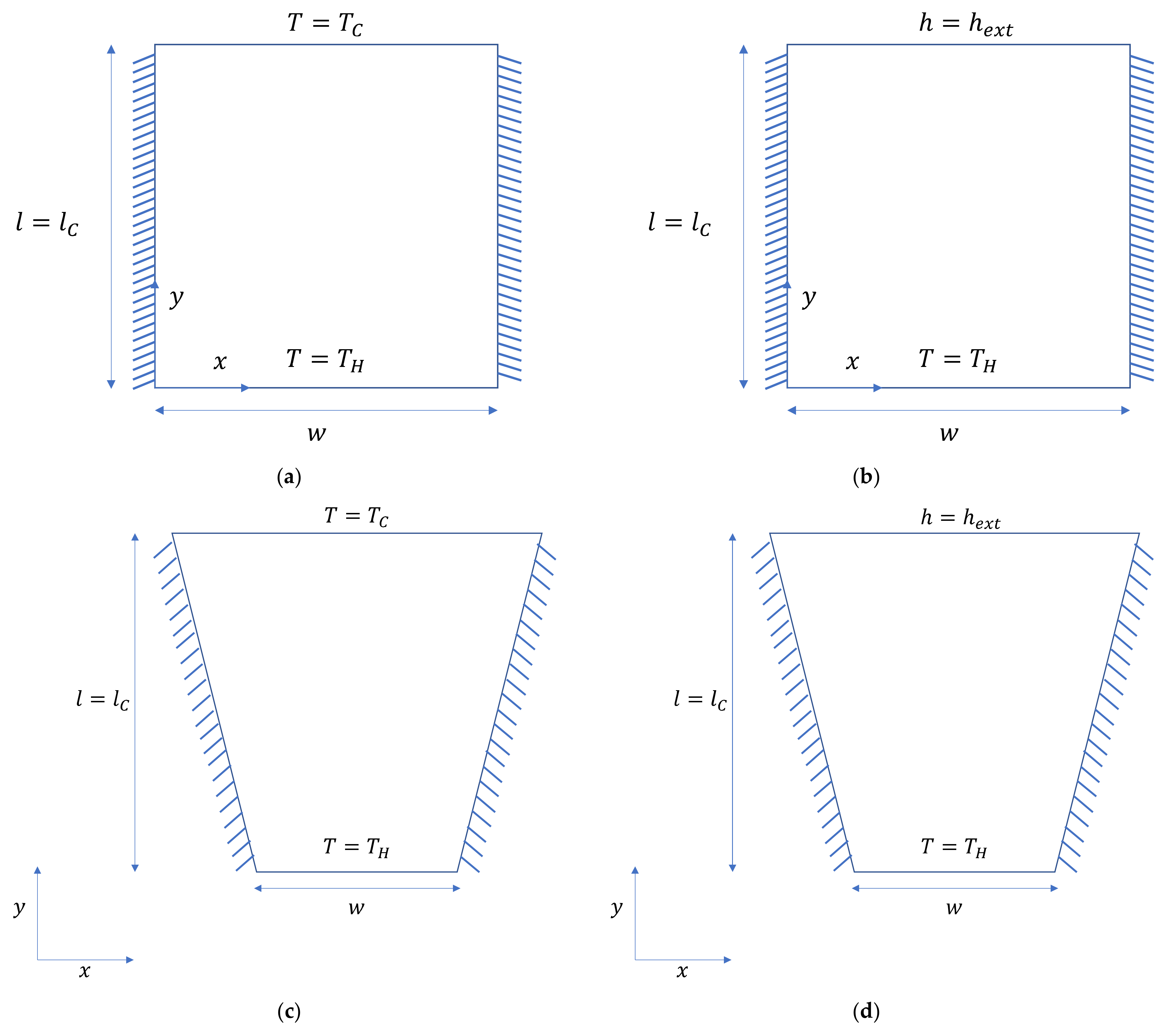
2.2. Physical Model and Boundary Conditions

Two categories of fundamental geometries are taken into consideration for the task at hand. One is a trapezoidal shape, whereas the first is rectangular. At first, the fluid zone is believed to be still. It is assumed that the bottom wall is a hot, continuously warming wall. We consider sidewalls to be adiabatic. The internal emissivity of both sidewalls is assumed to be 0.1, whereas the top wall’s internal emissivity is assumed to be 0.9. Figure 2a–d shows, respectively, the physical model with boundary conditions and the nomenclature for rectangular cavities and trapezoidal cavities.
Thermo-physical properties of air for different mean temperatures (To) are taken from [37]. For the problem under consideration, four cases are considered, which are described in Table 1. For all cases, parameters varied are aspect ratio (AR), which is the ratio height (l) to width (w) ratio of the cavity; Rayleigh number (Ra); and emissivity of the bottom wall (εb). The absolute temperature ratio T* is the ratio between TH and TC for Case 1 and Case 3, while it is the ratio between and T for Case 2 and Case 4.
The height of the cavity is used to determine the Rayleigh number (Ra). One new non-dimensional parameter, the external convection Nusselt number (Nuext), which is determined by Equation (7), is defined for cases 2 and 4.
N u e x t = h e x t W t o p k a i r
Variations in values of different parameters are given below:
A R = 1 , A R = 0.75 , A R = 0.5
ε b = 0.1 ,   ε b = 0.3 , ε b = 0.5
R a = 10 4 , R a = 10 5 , R a = 10 6 , R a = 10 7
N u e x t = 35 , N u e x t = 65 , N u e x t = 95
T * = 1.33 , T * = 1.5 , T * = 1.67
The average Nusselt number (Nu) value of the top wall is calculated from the formula given in Equation (8),
N u = l c k ( Q A Δ T )
where l c is the characteristic length of Nu and is equal to the width of the top wall. For the calculation of the convective Nusselt number (Nuc), the convective component of Q is used in the equation; for the calculation of the radiative Nusselt number (Nur), the radiative value of Q is used in the equation.

2.3. Solution Procedure

The CFD commercial program Ansys Fluent® [38] is used to solve the governing equations. The solution employs the SIMPLEC algorithm, and it is based on the pressure correction method. The momentum and energy equations are differentiated using the second-order upwind differencing procedure when the normalized residual for the momentum and mass equations is 10−5, and for the energy equations is 10−6 and the solution is said to have adequately converged. The thermophysical properties of air, steel, and glass are mentioned in Appendix A and the flowchart depicting the current methodology is shown in Appendix B.

3. Results and Discussion

3.1. Grid Independence Study

A computational mesh was created, which depicts the number of grid cells vs. the values of the convective Nusselt number (Nuc). The square cavity issue with a Rayleigh number (Ra) of 103 was explored for grid independence. With 10,000 cells, the Nusselt values become virtually independent of the grid size; hence, 10,000 cells are used for all simulations (Table 2).

3.2. Verification of Numerical Procedure

The numerical procedure was verified using the benchmark solution proposed byDe Vahl Davis [3]. For the verification of the numerical process, the square cavity issue with isothermal side walls (one hot and one cold) and adiabatic top and bottom walls were considered. The medium of the enclosure is air. Table 3 depicts the difference between the current values and those supplied in the benchmark solution. The values are seen to be in good agreement with the benchmark solution.
The problem considered for the verification of radiation is given in Figure 3. Obtaining the net radiation transfer from surface A1 is the objective. The solution from [39] is found to be 9874 W. The simulated value from the present methodology is found to be 9598.56 W. The error was below 2.79%.
Hence, the present methodology has to be considered to conduct further research concerning conjugate heat transfer having convection and radiation.
Numerical simulations are performed for rectangular and trapezoidal two-dimensional structures with radiating surfaces. The five factors considered here are the external Nusselt number (Nuext), the Rayleigh number (Ra), the aspect ratio (AR), the emissivity (ε), and the temperature ratio (T*). The impact of altering these parameters on the average Nusselt number (Nu) values at the top cold wall is covered in this section.

3.3. Heat Transfer Characteristics with Radiation Ignored

The effect of the Rayleigh number (Ra) and the aspect ratio is considered for a rectangular cavity in this section. The Rayleigh number (Ra) value can be obtained by using the formula given in Equation (9):
R a = g β Δ T l c 3 ϑ α
For the problem studied, the Rayleigh number (Ra) value is varied. The plot of Nu vs. Ra for case 1 to case 4, and for different aspect ratios it is shown in Figure 4.
With the increase in the Rayleigh number (Ra), the average Nusselt number across the top wall (Nu) increases for all four cases. The rise in Ra causes an increase in buoyant force relative to viscous force. The Nusselt number (Nu) varies significantly with the Rayleigh number (Ra) for lower aspect ratios. This pattern applies to both rectangular and trapezoidal cavities. At a given value, the Nu value of a trapezoidal cavity is greater than that of a rectangular cavity, indicating that more heat transfer over the top wall occurs in the trapezoidal cavity.

3.4. Heat Transfer Characteristics with Radiation Considered

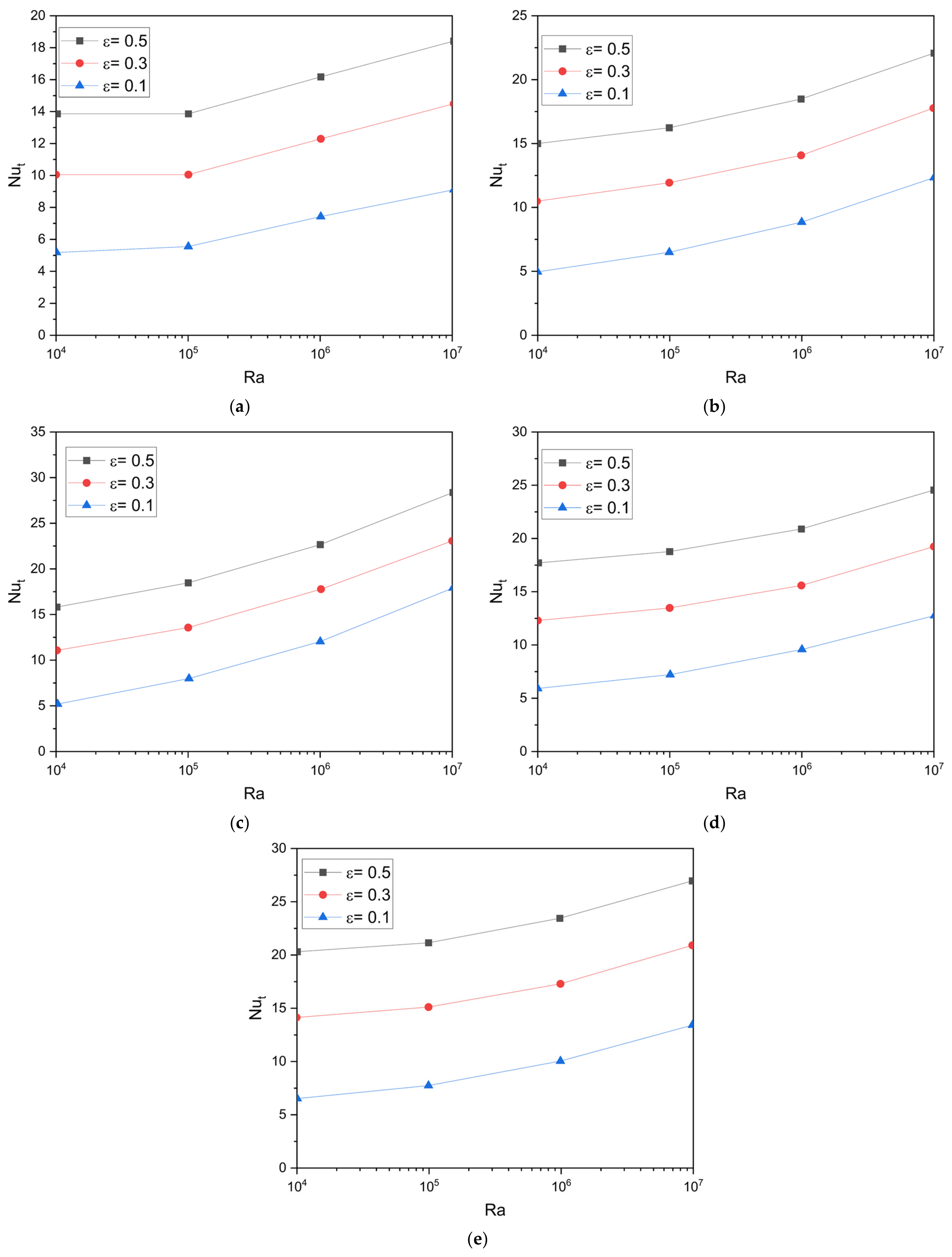
3.4.1. Effect of Emissivity
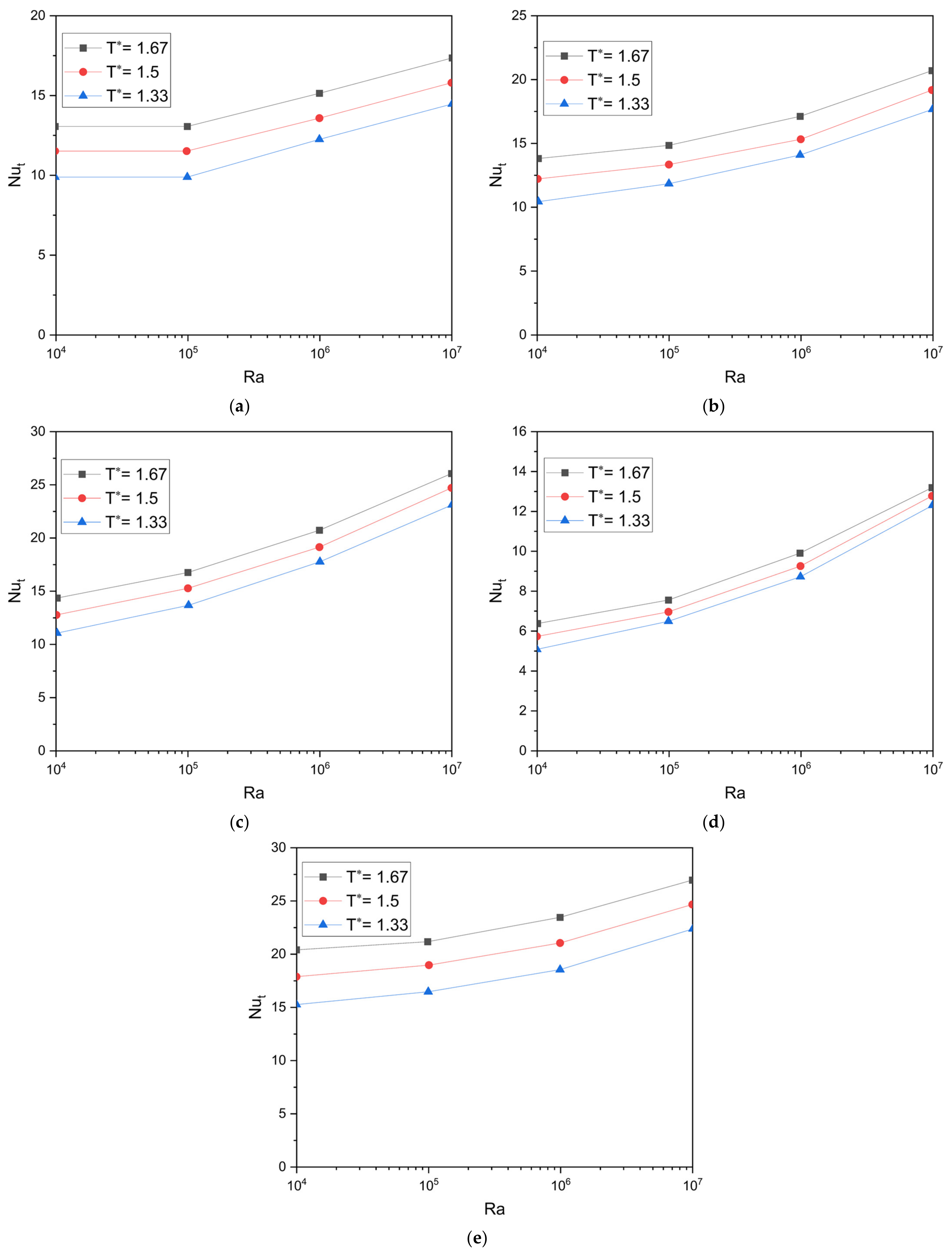
The effect of the variation of the emissivity of the hot bottom plate (εb) for different aspect ratios (AR) and T* values for Case 1 is shown in Figure 5. With the increase in emissivity, the total Nusselt number (Nut) is found to increase. This is mainly due to the increase in the radiation heat transfer rate while the contribution of the convective heat transfer rate is negligible. It is also observed that with an increase in aspect ratio, the change in the total Nusselt number (Nut) with εb as well as with the Rayleigh number (Ra) is more. The change in Nut is also independent of Ra value as emissivity plots are parallel to each other. A similar trend is also observed for different AR and T* values. It is also observed that for the same emissivity, the value Nut is more in the case of a higher T* value, as radiation heat transfer becomes significant for the higher T* value. Moreover, Nut is more for higher aspect ratio values.
The effect of the variation of the emissivity of the hot bottom plate (εb) for different aspect ratios and T* values for Case 3 is shown in Figure 6. A similar trend is observed in the case of the trapezoidal cavity, as in Case 1 for the respective values of AR and T*. It is also observed that the Nusselt number (Nut) value is more in the case of a trapezoidal cavity than a rectangular cavity for a particular aspect ratio, T*, and emissivity (ε).

3.4.2. Effect of T*

The effect of the variation of the T* value for the different aspect ratio (AR) and the emissivity (εb) values for Case 1 is shown in Figure 7. With the increase in T*, the total Nusselt number (Nut) is found to be increased. This is mainly due to an increase in the radiation heat transfer rate, while the contribution of the convective heat transfer rate is negligible. However, the change in the total Nusselt number (Nut) from εb = 0.1 to εb = 0.5 is greater than that from T* = 1.33 to T* = 1.67. It is also observed that the change in the Nusselt number (Nut) value is almost the same from T* = 1.33 to T* = 1.5 as from T* = 1.5 to T* = 1.67. The same trend is observed for different AR and εb values, too. For the same T* value, Nut is also more in the case of higher emissivity and a higher aspect ratio value. For the higher εb value, the variation of Nut with T* is also larger compared with lower emissivity values.
The effect of the variation of the T* value for the different aspect ratio (AR) and the emissivity (εb) values for Case 3 is shown in Figure 8. A similar trend is observed in the case of the trapezoidal cavity, as in Case 1 for respective values of εb and AR. The only difference in the case of Case 3 was that the value of Nut was more than the corresponding value in Case 1.

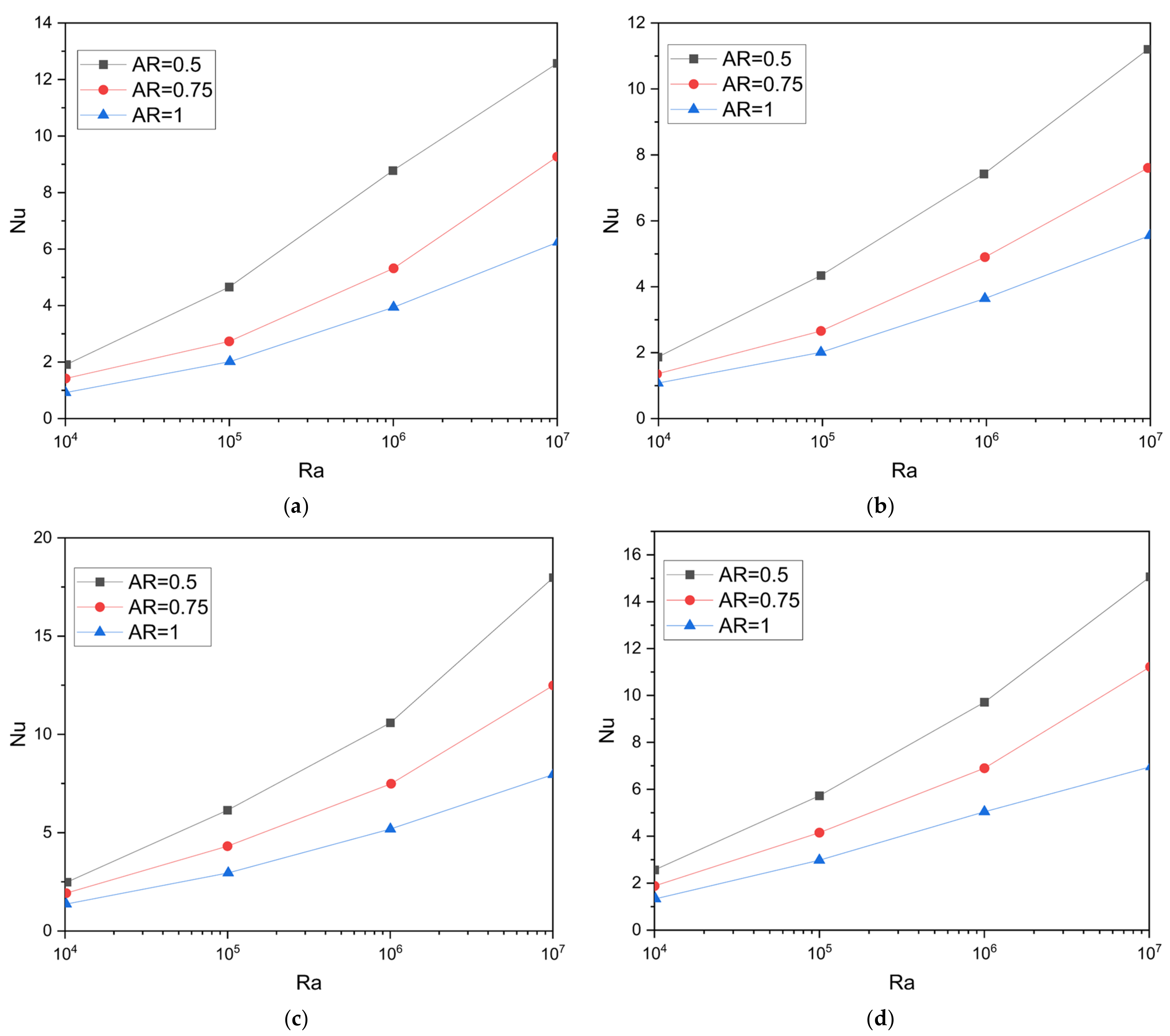
3.4.3. Effect of Aspect Ratio (AR)

The effect of variation of the Aspect Ratio (AR) value for different T* values and emissivity (εb) values for Case 1 is shown in Figure 9. It is observed that with the increase in AR value, the total Nusselt number (Nut) decreases. The heat transfer rate across the top wall increases due to a decrease in thermal resistance because of the decrease in the height of the cavity. This variation in the total Nusselt number (Nut) value with AR is mainly due to the variation of convective heat transfer, while the radiation heat transfer rate changes negligibly with AR. It can also be observed that the change in Nut value with the aspect ratio (AR) is less for the lower Rayleigh number (Ra) values than for the higher Ra values. The effect of the aspect ratio is also negligible in the case of Ra = 103 because of very little convection presence. A similar trend is observed for different εb and T* values. Nut values are also larger in the case of higher emissivity and T* values.
The effect of variation of the Aspect Ratio (AR) value for different T* values and emissivity (εb) values for Case 3 is shown in Figure 10. The same trends are observed in Case 3 as in Case 1, except that the variation of Nut with an aspect ratio (AR) is uniform for all the Rayleigh number (Ra) values. The value of the total Nusselt number (Nut) is more in Case 3 than the corresponding value in Case 1.

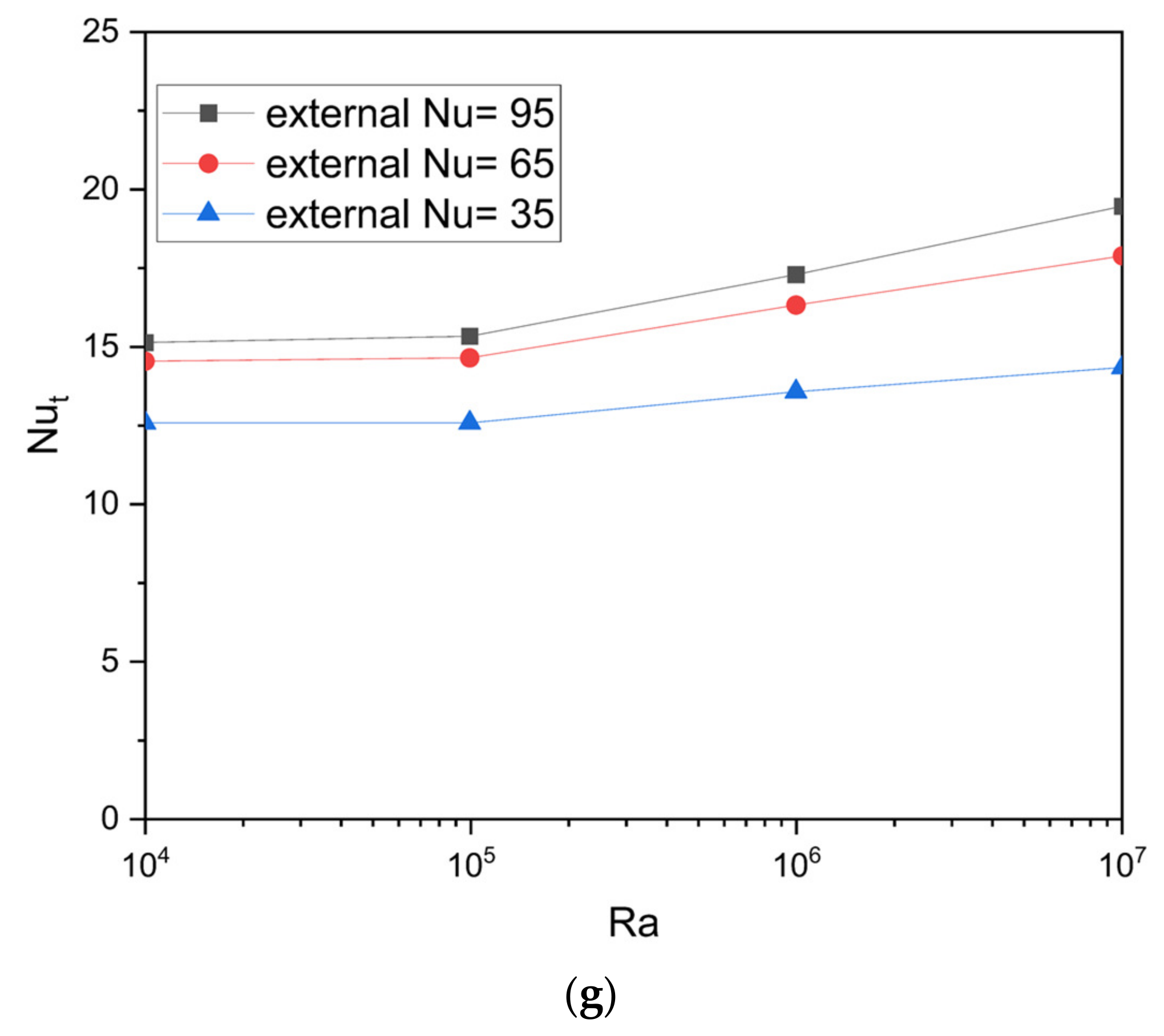
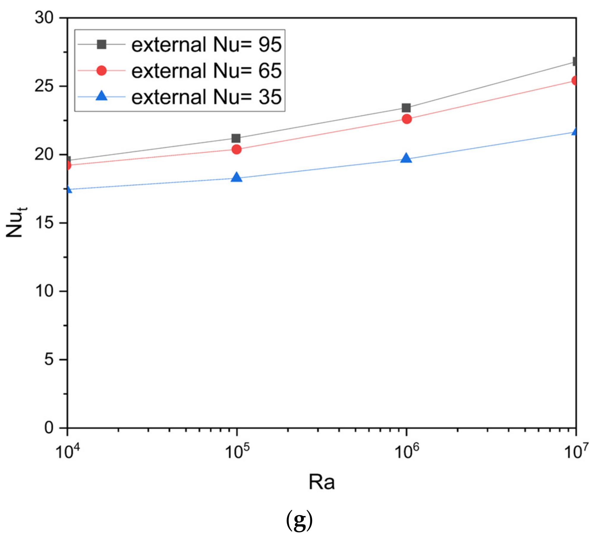
3.4.4. Effect of External Nusselt Number (Nuext)

The effect of the variation of the external Nusselt number (Nuext) for different T* values, emissivity (εb) values, and aspect ratios (AR) values for Case 2 is shown in Figure 11. It is observed that as the external Nusselt number (Nuext) increases, the total Nusselt number (Nut) increases. This rise in Nut is due to an increase in both convection heat transfer and radiation heat transfer rate as a result of the increase in the external Nusselt number. The temperature differential between the hot wall and the bottom wall grows when external heat transfer from the top wall decreases the temperature of the top wall relative to the lack of external heat transfer. This is because they are temperature differential dependent and absolute temperature dependent, and both the convective and radiation heat transfer rates are growing. For lower Rayleigh number (Ra) values, the effect of the external Nusselt number is less compared to that of higher Ra values. It is also observed that the change in the total Nusselt number (Nut) value from Nuext = 35 to Nuext = 65 is more than that from Nuext = 65 to Nuext = 95. A similar trend is observed for different T*, AR, and εb values.
The effect of variation of the external Nusselt number for different T* values, emissivity (εb) values, and aspect ratios (AR) values for Case 4 is shown in Figure 12. A similar trend is observed in Case 4 as in Case 2, except that variation in the total Nusselt number (Nut) with the external Nusselt number is less compared with that in Case 2. This may be because, for the same aspect ratio (AR), the top wall width is more in the case of a trapezoidal cavity than a rectangular cavity.

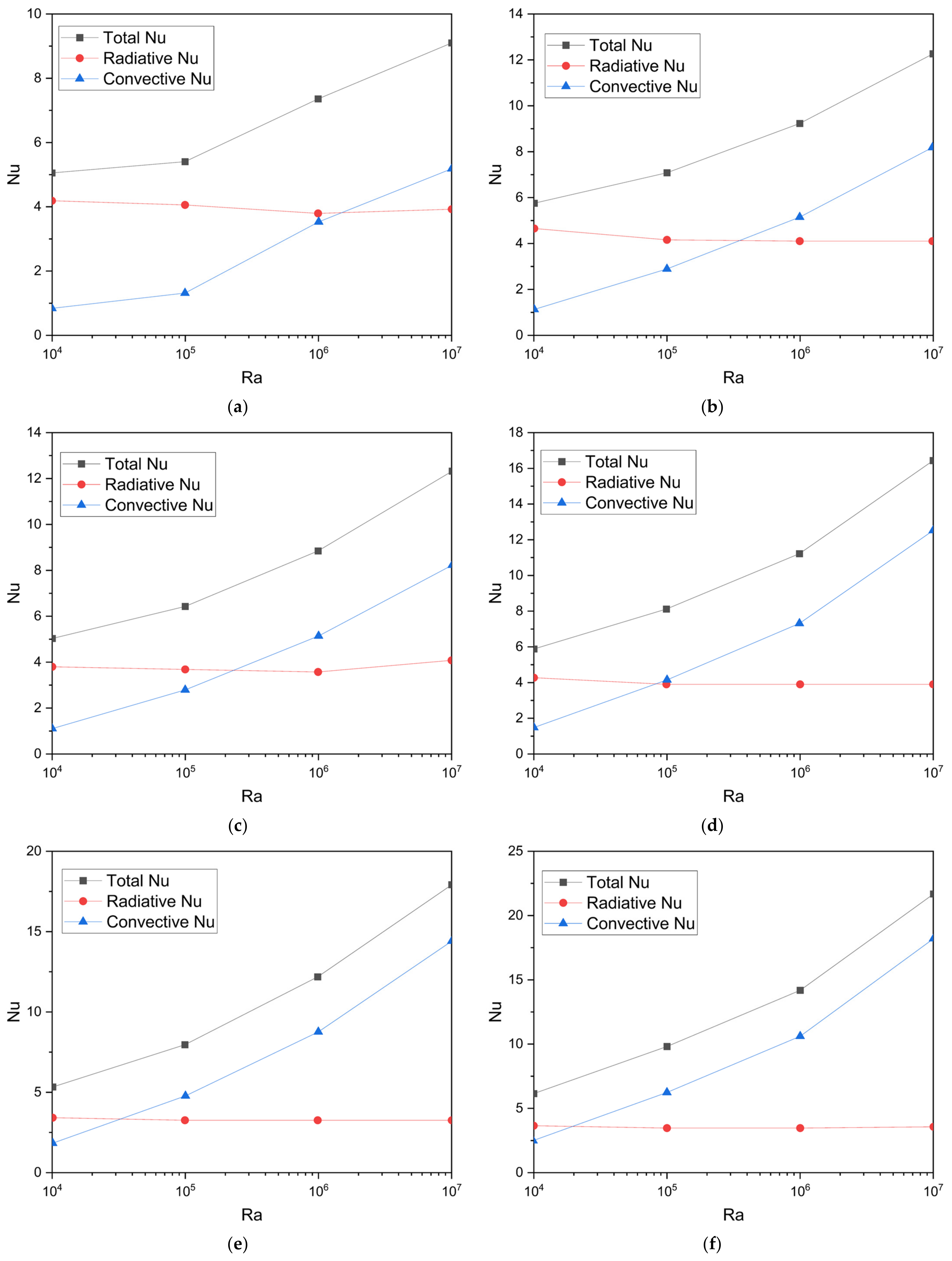
3.4.5. Composition of Radiative and Convective Components

As previously stated, heat loss from the top wall is greater in the trapezoidal cavity than in the rectangular cavity for the same AR, T*, and εb values, as shown in Figure 13. It can also be shown that when the Rayleigh number (Ra) grows, only the convective Nusselt number (Nuc) increases, while the radiative Nusselt number (Nur) remains constant.

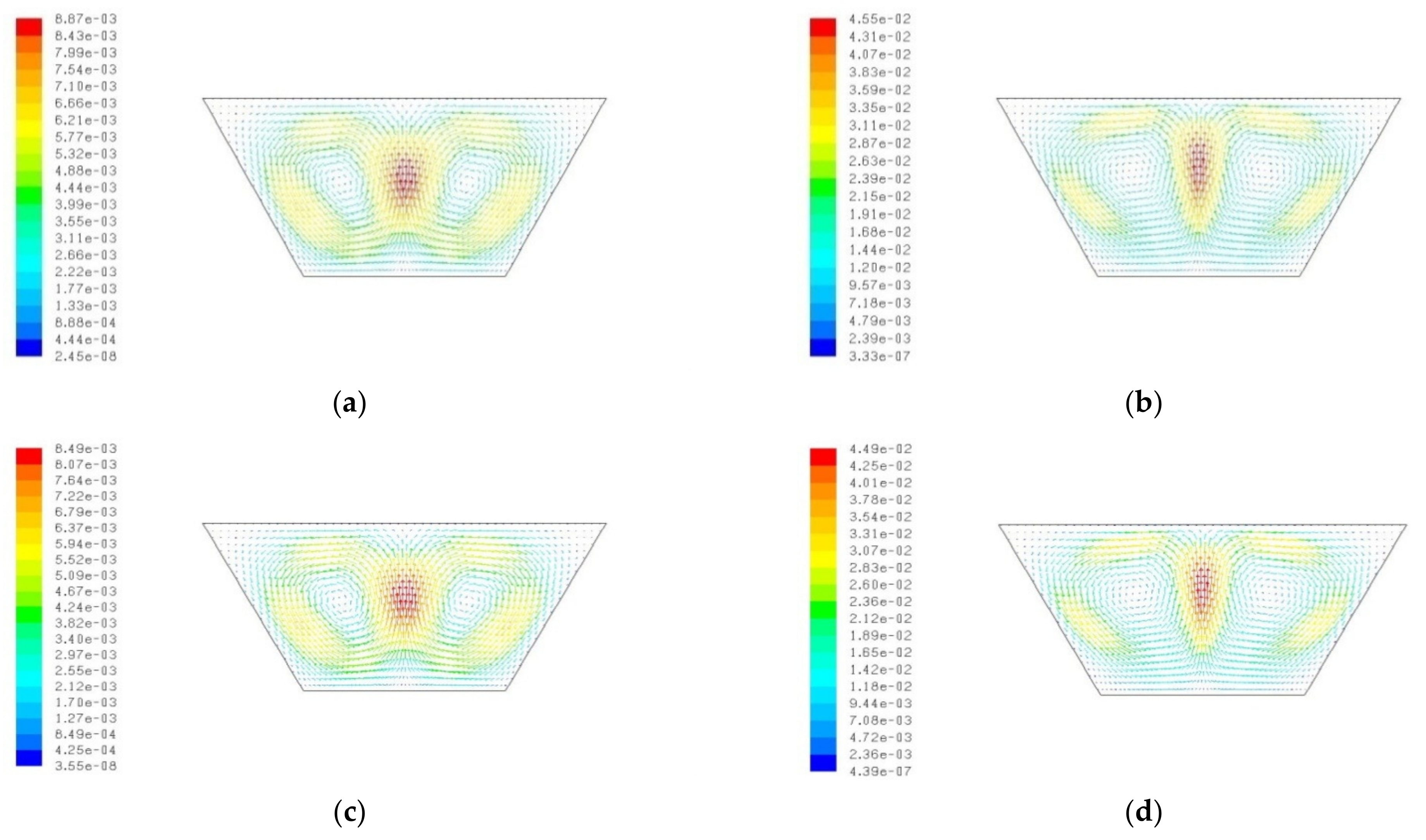
3.4.6. Heat Flow Characteristics

The isotherms for Ra = 104 and Ra = 105 with εb = 0.1 and 0.5 for AR = 1 are shown in Figure 14 and Figure 15. For this graphic, the temperature is non-dimensionalized, meaning it ranges from 0 to 1 from bottom to top. Isotherms at Ra = 104 are almost horizontal for both emissivity values because viscous forces dominate over buoyancy forces, resulting in pure conduction-like isotherms. Isotherms with Ra = 105 and εb = 0.1 reveal that spontaneous convection flow occurs in two cells symmetric to the center vertical plane, as illustrated in Figure 16b. Moreover, isotherms are more packed along the bottom and top walls, indicating a greater temperature differential in that region, resulting in significant heat transfer near these walls. Four cells emerged in the case of Ra = 104 and εb = 0.5, demonstrating the huge ratio of radiative heat transfer and the convective heat transfer rate seen in Figure 16c. In the case of Ra = 105 and εb = 0.5, though, isotherms indicate the unicellular flow of the air in a clockwise direction, as shown in Figure 16d. For Ra = 106 and εb = 0.1, isotherms are erratic, indicating a transition from laminar to turbulent, while in the case of εb = 0.1, even at Ra = 106, isotherms are not erratic, indicating the shift of the transition Rayleigh number to the higher Ra values. Similar trends are seen in the case of AR = 0.75, while in the case of AR = 0.5, even at higher emissivity and Ra values, bicellular flow is observed.
Figure 15 shows the isotherms for Ra = 104 and Ra = 105 with εb = 0.1 and 0.5 for AR = 1. Bicellular flow occurs in the trapezoidal cavity for all aspect ratios and emissivity values, according to Figure 17. At Ra = 104, isotherms have uniform spacing. Isotherms, on the other hand, are more densely packed along the top and bottom walls, with higher Rayleigh number (Ra) values, indicating high-temperature gradients and enhanced heat transfer rates in these places.

3.5. Development of Empirical Correlation

For more general use, correlations for the average total Nusselt number were developed concerning influencing parameters such as the Rayleigh number, aspect ratio, emissivity, absolute temperature ratio, and the Nusselt external (due to wind). Log-linear regression analysis was used to calculate the coefficients and the exponents of the association. The relations were obtained using around 525 data sets. The correlation parity plots are provided in Figure 18 and depict correlated data and CFD data. Modest correlation values ranging from 0.902 to 0.993 suggest a decent match. Moreover, more than 90% of the connected data point falls range from 3% to 10%.
For Case 1 and Case 3, the correlation is:
N u t = 3.16 × R a 0.08 ( 1 + A R ) 0.901 ( 1 + ε ) 2.81 T * 0.76
For Case 2 and Case 4, the correlation is:
N u t = 1.78 × R a 0.06 ( 1 + A R ) 0.707 ( 1 + ε ) 2.63 T * 0.65 N u e x t 0.16
The range parameter for which these correlations are valid is as follows:
A R = 0.5 1
ε b = 0.1 0.5
R a = 10 4 10 7
T * = 1.33 1.67
N u e x t = 35 95
It can be seen from Equations (10) and (11) that the exponent of emissivity and T* has an important role in the total Nusselt number followed by the Rayleigh number. The aspect ratio has less influence on the Nusselt number. The external Nusselt number is also an important parameter for Case 2 and Case 4. The parity plot showing a comparison of the average total Nusselt number between the CFD and the correlated data is shown in Figure 18a,b.

4. Conclusions and Future Work

4.1. Conclusions

The computational approach was used to analyse the heat loss through radiation and the continuous laminar two-dimensional natural convection flow in an enclosure of a cooker with a hot bottom wall, a cold top wall, or wind-induced convection loss at the top and adiabatic sidewalls. The cavity medium, air, is assumed to be non-participating. Convection and radiation losses were calculated from the top wall. The impacts of the form (rectangular and trapezoidal) and other factors, such as T*, the emissivity of the bottom surface (εb), the external Nusselt number (Nuext) across the top wall, the aspect ratio (AR) of the cavity, and the Rayleigh number (Ra) values have all been studied. Calculations have been made to determine the average Nusselt number (Nut), the Nusselt number (Nuc), and the Nusselt number (Nur) throughout the top wall of the cavity.
It was observed that when the aspect ratio (AR) of the cavity lowers and the exterior Nusselt number (Nuext), emissivity of the bottom surface (b), and T* all increase, so does the average total Nusselt number (Nut). Additionally, the emissivity of the bottom surface (b) and T* have little effect on the rate of convective heat transfer across the top wall, but radiative heat transfer increases. Both convective and radiative heat transfer, meanwhile, contribute to the change in the total heat transfer rate when the aspect ratio (AR) of the cavity and the external Nusselt number (Nuext) across the top wall change. In the case of a trapezoidal cavity, the average total Nusselt number (Nut), for the identical boundary conditions and aspect ratio (AR), is higher than in the case of the rectangular cavity. The results from the computational studies were used to obtain a correlation between the total average Nusselt number and its influencing parameters.

4.2. Future Scope

The fluid taken in the cavity, air, is supposed to be non-participating in the current situation. Heat transfer analysis may be performed using air as the participating medium. The thickness of the hollow walls is believed to be minimal in the current situation. Comparable research may be carried out by taking a correct finite value of the thickness of the walls. To replicate comparable cavities for solar applications, hot wall boundary conditions can be adjusted to have incident radiation value.

Author Contributions

Formal analysis, A.S. (Abhisek Sarangi) and A.S. (Asish Sarangi); Resources, M.M.A.; Data curation, A.S. (Abhisek Sarangi) and A.S. (Ashish Sarangi); Writing—original draft, A.S. (Abhisek Sarangi) and A.S. (Ashish Sarangi); Writing—review & editing, S.S.S., R.K.M. and M.M.A.; Supervision, S.S.S. and R.K.M. All authors have read and agreed to the published version of the manuscript.

Funding

The corresponding author (Sudhansu Sekhar Sahoo) thankfully acknowledges the financial support from the State Council on Science & Technology, the Science & Technology Department, and the Government of Odisha under research grant ST-SCST-MISC-0061/2018 2682/ dated 24 June 2019 to carry out this project. The APC for publishing the article has been funded by the Corresponding author, Mohamed M. Awad.

Data Availability Statement

The data that support the findings of this study are available from the corresponding author, [SSS], upon reasonable request.

Conflicts of Interest

The authors declare no conflict of interest.

Nomenclatures

aGas absorption coefficient
ARAspect ratio = height to top width ratio
GrGrashof number = g β Δ T l c 3 ϑ 2
gGravitational Acceleration (m/s2)
hHeat transfer coefficient (W/m2/K)
hextExternal heat transfer coefficient over the top wall (W/m2/K)
IRadiation Intensity (energy per area of emitting surface per unit solid angle)
kThermal Conductivity (W/m/K)
lcCharacteristic length or height or top width for Ra, Gr and Nu(m)
NuNusselt number =  h l c k
NucAverage convective Nusselt number
NurAverage radiative Nusselt number
NutAverage total Nusselt number
NuextExternal Nusselt number
PPressure (Pa)
QHeat transfer rate (W)
QcConvective heat transfer rate (W)
QrRadiative heat transfer rate (W)
QtTotal Heat transfer rate (W)
RaRayleigh number = g β Δ T l c 3 ϑ α
TTemperature (K)
TCCold wall temperature (K)
THHot wall temperature (K)
ToMean temperature = T H + T C 2 (K)
TFree stream temperature (K)
ΔTTemperature difference = THTC or THT(K)
T*Temperature ratio = T H T C or T H T
WWidth of the cavity (m)
WtopWidth of the cavity at top(m)
Greek Symbols
αThermal diffusivity (m2/s)
βCoefficient of thermal expansion (K−1)
εEmissivity
εbEmissivity of bottom surface
σStefan Boltzmann constant (5.67 × 10⁻⁸ W/m2K4)
υKinematic viscosity (m2/s)
ρDensity (kg/m3)

Appendix A

Table A1. Thermo-physical properties of air at different T* values and that for steel and glass.
T*Density [kg/m3]Specific Heat (Cp) [j/kg·K]Thermal Conductivity [w/m·K]Viscosity [kg/m·s]Thermal Expansion Coefficient [1/K]
Air1.331.0110090.02972.084 × 10−50.002857
1.50.94121009.40.031542.3277 × 10−50.0026667
1.670.882610130.0333252.6042 × 10−50.0025
Steel 8030502.4816.27nilnil
Glass 26008401.05nilnil

Appendix B

Figure A1. Flow chart depicting the methodology adopted in the present work.
Energies 16 03868 g0a1

References

  1. Sahoo, S.S.; Singh, S.; Banerjee, R. Analysis of heat loss from a trapezoidal cavity used for linear Fresnel reflector system. Sol. Energy 2012, 86, 1313–1322. [Google Scholar] [CrossRef]
  2. Nayak, J.; Agrawal, M.; Mishra, S.; Sahoo, S.S.; Swain, R.K.; Mishra, A. Combined heat loss analysis of trapezoidal shaped solar cooker cavity using computational approach. Case Stud. Therm. Eng. 2018, 12, 94–103. [Google Scholar] [CrossRef]
  3. De Vahl Davis, G. Natural convection of Air in a square cavity: A benchmark numerical solution. Int. J. Numer. Methods Fluids 1983, 3, 249–264. [Google Scholar] [CrossRef]
  4. Behnia, M.; Reizes, J.A.; De Vahl Davis, G. Combined radiation and natural convection in a rectangular cavity with a transparent wall and containing a non-participating fluid. Int. J. Numer. Methods Fluids 1990, 10, 305–325. [Google Scholar] [CrossRef]
  5. Moghimi, M.; Mirgolbabaei, H.; Miansari, M.; Miansari, M. Natural convection in rectangular enclosures heated from below and cooled from above. Aust. J. Basic Appl. Sci. 2009, 3, 4618–4623. [Google Scholar]
  6. Ramesh, N.; Venkateshan, S.P. Effect of surface radiation on natural convection in a square enclosure. J. Thermophys. Heat Transf. 1999, 13, 299–301. [Google Scholar] [CrossRef]
  7. Nithyadevi, N.; Kandaswamy, P.; Lee, J. Natural convection in a rectangular cavity with partially active side walls. Int. J. Heat Mass Transf. 2007, 50, 4688–4697. [Google Scholar] [CrossRef]
  8. Ridouane, E.H.; Hasnaoui, M.; Amahmid, A.; Raji, A. Interaction between natural convection and radiation in a square cavity heated from below. Numer. Heat Transf. Part A 2004, 45, 289–311. [Google Scholar] [CrossRef]
  9. Ridouane, E.H.; Hasnaoui, M.; Campo, A. Effects of surface radiation on natural convection in a Rayleigh–Benard square enclosure: Steady and unsteady conditions. Heat Mass Transf. 2006, 42, 214–225. [Google Scholar] [CrossRef]
  10. Gad, M.A.; Balaji, C. Effect of surface radiation on RBC in cavities heated from below. Int. Commun. Heat Mass Transf. 2010, 37, 1459–1464. [Google Scholar] [CrossRef]
  11. Varol, Y.; Oztop, H.F.; Pop, I. Maximum density effects on buoyancy-driven convection in a porous trapezoidal cavity. Int. Commun. Heat Mass Transf. 2010, 37, 401–409. [Google Scholar] [CrossRef]
  12. Balaji, C.; Venkateshan, S.P. Interaction of surface radiation with free convection in a square cavity. Int. J. Heat Fluid Flow 1993, 14, 260–267. [Google Scholar] [CrossRef]
  13. Balaji, C.; Venkateshan, S.P. Correlations for free convection and surface radiation in a square cavity. Int. J. Heat Fluid Flow 1994, 15, 249–251. [Google Scholar] [CrossRef]
  14. Sagade, A.A.; Samdarshi, S.K.; Lahkar, P.J.; Sagade, N.A. Experimental determination of the thermal performance of a solar box cooker with a modified cooking pot. Renew. Energy 2020, 150, 1001–1009. [Google Scholar] [CrossRef]
  15. Hosseinzadeh, M.; Faezian, A.; Mirzababaee, S.M.; Zamani, H. Parametric analysis and optimization of a portable evacuated tube solar cooker. Energy 2020, 194, 116816. [Google Scholar] [CrossRef]
  16. Coccia, G.; Aquilanti, A.; Tomassetti, S.; Comodi, G.; Di Nicola, G. Design, realization, and tests of a portable solar box cooker coupled with an erythritol-based PCM thermal energy storage. Sol. Energy 2020, 201, 530–540. [Google Scholar] [CrossRef]
  17. Bhave, A.G.; Kale, C.K. Development of a thermal storage e type solar cooker for high temperature cooking using solar salt. Sol. Energy Mater. Sol. Cell 2020, 208, 110394. [Google Scholar] [CrossRef]
  18. Palanikumar, G.; Shanmugan, S.; Chithambaram, V.; Gorjian, S.; Pruncu, C.I.; Essa, F.A.; Kabeel, A.E.; Panchal, H.; Janarthanan, B.; Ebadi, H.; et al. Thermal investigation of a solar box-type cooker with nano composite phase change materials using flexible thermography. Renew. Energy 2021, 178, 260–282. [Google Scholar] [CrossRef]
  19. Anilkumar, B.C.; Maniyeri, R.; Anish, S. Design, fabrication and performance assessment of a solar cooker with optimum composition of heat storage materials. Environ. Sci. Pollut. Res. 2021, 28, 63629–63637. [Google Scholar] [CrossRef]
  20. Cuce, P.M.; Kolayli, S.; Cuce, E. Enhanced performance figures of solar cookers through latent heat storage and low-cost booster reflectors. Int. J. Low-Carbon Technol. 2020, 15, 427–433. [Google Scholar] [CrossRef]
  21. Vishwakarma, A.; Sinha, S. Box type solar cooker with thermal storage: An overview. Energy Syst. 2022. [Google Scholar] [CrossRef]
  22. Panchal, H.; Sadasivuni, K.K. Investigation and performance analysis of Schefler reflector solar cooking system integrated with sensible and latent heat storage materials. Int. J. Ambient Energy 2020, 41, 1096–1105. [Google Scholar] [CrossRef]
  23. Nayak, J.; Sahoo, S.S.; Swain, R.K.; Mishra, A. Heat loss modeling and analysis of solar cooker cavity: An analytical approach. In Proceedings of the 2016 International Conference on Electrical, Electronics, and Optimization Techniques (ICEEOT), Chennai, India, 3–5 March 2016; pp. 454–459. [Google Scholar] [CrossRef]
  24. Nayak, J.; Sahoo, S.S.; Swain, R.K.; Mishra, A.; Chakrabarty, S. Construction of Box Type Solar Cooker and Its Adaptability to Industrialized Zone. Mater. Today Proc. 2017, 4, 12565–12570. [Google Scholar] [CrossRef]
  25. Nayak, J.; Sahoo, S.S.; Swain, R.K.; Mishra, A.; Thomas, S. Thermal Performance Analysis of a Box-Type Solar Cooker with Finned Pot: An Experimental Approach. In Advances in Smart Grid and Renewable Energy; SenGupta, S., Zobaa, A.F., Sherpa, K.S., Bhoi, A.K., Eds.; Lecture Notes in Electrical Engineering; Springer: Singapore, 2018; Volume 435. [Google Scholar] [CrossRef]
  26. Hosseinzadeh, M.; Sadeghirad, R.; Zamani, H.; Kianifar, A.; Mirzababaee, S.M. The performance improvement of an indirect solar cooker using multi-walled carbon nanotube-oil nanofluid: An experimental study with thermodynamic analysis. Renew. Energy 2021, 165, 14–24. [Google Scholar] [CrossRef]
  27. Kumar, A.; Saxena, A.; Pandey, S.D.; Joshi, S.K. Design and performance characteristics of a solar box cooker with phase change material: A feasibility study for Uttarakhand region, India. Appl. Therm. Eng. 2022, 208, 118196. [Google Scholar] [CrossRef]
  28. Khallaf, A.M.; Tawfik, M.A.; El-Sebaii, A.A.; Sagade, A.A. Mathematical modeling and experimental validation of the thermal performance of a novel design solar cooker. Sol. Energy 2020, 207, 40–50. [Google Scholar] [CrossRef]
  29. El Moussaoui, N.; Talbi, S.; Atmane, I.; Kassmi, K.; Schwarzer, K.; Chayeb, H.; Bachiri, N. Feasibility of a new Design of a Parabolic Trough Solar Thermal Cooker (PSTC). Sol. Energy 2020, 201, 866–871. [Google Scholar] [CrossRef]
  30. Hosseinzadeh, M.; Sadeghirad, R.; Zamani, H.; Kianifar, A.; Mirzababaee, S.M.; Faezian, A. Experimental study of a nano fluid-based in direct solar cooker: Energy and exergy analyses. Sol. Energy Mater. Sol. Cells 2021, 221, 110879. [Google Scholar] [CrossRef]
  31. Kajumba, P.K.; Okello, D.; Nyeinga, K.; Nydal, O.J. Experimental investigation of a cooking unit integrated with thermal energy storage system. J. Energy Storage 2020, 32, 101949. [Google Scholar] [CrossRef]
  32. Nayak, N.; Abu Jarir, H.; Al Ghassani, H. Solar Cooker Study under Oman Conditions for Late Evening Cooking Using Stearic Acid and Acetanilide as PCM Materials. J. Sol. Energy 2016, 2016, 2305875. [Google Scholar] [CrossRef]
  33. Saxena, A.; Cuce, E.; Tiwari, G.N.; Kumar, A. Design and thermal performance investigation of a box cooker with flexible solar collector tubes: An experimental research. Energy 2020, 206, 118144. [Google Scholar] [CrossRef]
  34. Ndukwu, M.C.; Bennamoun, L.; Simo-Tagne, M. Reviewing the exergy analysis of solar thermal systems integrated with phase change materials. Energies 2021, 14, 724. [Google Scholar] [CrossRef]
  35. Mofijur, M.; Mahlia, T.M.I.; Silitonga, A.S.; Ong, H.C.; Silakhori, M.; Hasan, M.H.; Putra, N.; Rahman, S. Phase change materials (PCM) for solar energy usages and storage: An overview. Energies 2019, 12, 3167. [Google Scholar] [CrossRef]
  36. Mlik, M.S.; Iftikhar, N.; Wadood, A.; Khan, M.O.; Asghar, M.U.; Khan, S.; Khurshaid, T.; Kim, K.C.; Rehman, Z.; Rizvi, S. Design and Fabrication of Solar Thermal Energy Storage System Using Potash Alumasa PCM. Energies 2020, 13, 6169. [Google Scholar] [CrossRef]
  37. The Engineering Tool Box. Available online: https://www.engineeringtoolbox.com (accessed on 1 March 2023).
  38. ANSYS Fluent® Manual 2022. (accessed on 1 March 2023).
  39. Incropera, F.P.; Dewitt, D.P.; Bergman, T.L.; Lavine, A.S. Principles of Heat and Mass Transfer, 7th ed.; Wiley: Hoboken, NJ, USA, 2013. [Google Scholar]
Figure 1. Simple box-type solar cooker [2].
Energies 16 03868 g001
Figure 2. Geometry and boundary conditions of (a) rectangular cavity with cold wall at the top, (b) rectangular cavity with convective heat loss at the top, (c) trapezoidal cavity with cold wall at the top, and (d) trapezoidal cavity with convective heat loss at the top.
Energies 16 03868 g002
Figure 3. Geometry for problem in [39].
Energies 16 03868 g003
Figure 4. Plot of Nu vs. Ra for (a) case 1, (b) case 2 at Nuext = 65, (c) case 3, and (d) case 4 at Nuext = 65.
Energies 16 03868 g004
Figure 5. Plot of Nut vs. Ra at different emissivities for Case 1 with (a) AR = 1, T* = 1.33, (b) AR = 0.75, T* = 1.33, (c) AR = 0.5, T* = 1.33, (d) AR = 0.75, T* = 1.5, (e) AR = 0.75, T* = 1.67.
Energies 16 03868 g005
Figure 6. Plot of Nut vs. Ra at different emissivities for case 3 with (a) AR = 1, T* = 1.33, (b) AR = 0.75, T* = 1.33, (c) AR = 0.5, T* = 1.33, (d) AR = 0.75, T* = 1.5, (e) AR = 0.75, T* = 1.67.
Energies 16 03868 g006
Figure 7. Plot of Nut vs. Ra for different T* for Case 1 with (a) AR = 1, εb = 0.3, (b) AR = 0.75, εb = 0.3, (c) AR = 0.5, εb = 0.3, (d) AR = 0.75, εb = 0.1, (e) AR = 0.75, εb = 0.5.
Energies 16 03868 g007
Figure 8. Plot of Nut vs. Ra at different T* for Case 3 with (a) AR = 1, εb = 0.3, (b) AR = 0.75, εb = 0.3, (c) AR = 0.5, εb = 0.3, (d) AR = 0.75, εb = 0.1, and (e) AR = 0.75, εb = 0.5.
Energies 16 03868 g008
Figure 9. Plot of Nut vs. Ra at different aspect ratios for Case 1 with (a) T* = 1.33, εb = 0.3, (b) T* = 1.5, εb = 0.3, (c) T* = 1.67, εb = 0.3, (d) T* = 1.5, εb = 0.1, and (e) T* = 1.67, εb = 0.5.
Energies 16 03868 g009
Figure 10. Plot of Nut vs. Ra at different aspect ratios for Case 3 with (a) T* = 1.33, εb = 0.3, (b) T* = 1.5, εb = 0.3, (c) T* = 1.67, εb = 0.3, (d) T* = 1.5, εb = 0.1, and (e) T* = 1.67, εb = 0.5.
Energies 16 03868 g010
Figure 11. Plot of Nut vs. Ra at different Nuext values for Case 2 with (a) T* = 1.33, εb = 0.3, AR = 1, (b) T* = 1.33, εb = 0.3, AR = 0.75, (c) T* = 1.33, εb = 0.3, AR = 0.5, (d) T* = 1.5, εb = 0.3, AR = 0.75, (e) T* = 1.67, εb = 0.3, AR = 0.75, (f) T* = 1.5, εb = 0.1, AR = 0.75, and (g) T* = 1.5, εb = 0.5, AR = 0.75.
Energies 16 03868 g011aEnergies 16 03868 g011b
Figure 12. Plot of Nut vs. Ra at different Nuext values for Case 4 with (a) T* = 1.33, εb = 0.3, AR = 1; (b) T* = 1.33, εb = 0.3, AR = 0.75; (c) T* = 1.33, εb = 0.3, AR = 0.5; (d) T* = 1.5, εb = 0.3, AR = 0.75; (e) T* = 1.67, εb = 0.3, AR = 0.75; (f) T* = 1.5, εb = 0.1, AR = 0.75; and (g) T* = 1.5, εb = 0.5, AR = 0.75.
Energies 16 03868 g012aEnergies 16 03868 g012b
Figure 13. Plot of log(Nu) vs. Ra with T* = 1.33, εb = 0.1 for (a) Case 1 with AR = 1, (b) Case 3 with AR = 1, (c) Case 1 with AR = 0.75, (d) Case 3 with AR = 0.75, (e) Case 1 with AR = 0.5, and (f) Case 3 with AR = 0.5.
Energies 16 03868 g013
Figure 14. Isotherms for the Case 1 and AR = 1 with (a) Ra = 104, εb = 0.1, (b) Ra = 105, εb = 0.1, (c) Ra = 104, εb = 0.5, and (d) Ra = 105, εb = 0.5.
Energies 16 03868 g014
Figure 15. Isotherms for the Case 3 and AR = 1 with (a) Ra = 104, εb = 0.1, (b) Ra = 105, εb = 0.1, (c) Ra = 104, εb = 0.5, and (d) Ra = 105, εb = 0.5.
Energies 16 03868 g015
Figure 16. Velocity vectors for the Case 1 and AR = 1 with (a) Ra = 104, εb = 0.1, (b) Ra = 105, εb = 0.1, (c) Ra = 104, εb = 0.5, and (d) Ra = 105, εb = 0.5.
Energies 16 03868 g016
Figure 17. Velocity vectors for the Case 3 and AR = 1 with (a) Ra = 104, εb = 0.1, (b) Ra = 105, εb = 0.1, (c) Ra = 104, εb = 0.5, and (d) Ra = 105, εb = 0.5.
Energies 16 03868 g017
Figure 18. Parity plot of total average Nusselt number of cookers: (a) Case 1 and Case 3, (b) Case 2 and Case 4.
Energies 16 03868 g018
Table 1. Cases considered for the present problem.
Shape of Geometry Top Wall Boundary Condition
Case 1RectangularIsothermal ( T = T c )
Case 2RectangularExternal heat transfer ( h = h e x t )
Case 3TrapezoidalIsothermal ( T = T c )
Case 4TrapezoidalExternal heat transfer ( h = h e x t )
Table 2. Grid Independence study.
No. of CellsNucNur
56251.0626537.379869
81001.0714717.546431
10,0001.074457.578917
Table 3. Comparison of the simulated Nusselt number (Nu) with benchmark Nu [3].
Rayleigh Number (Ra)Simulated Value of Nusselt Number (Nu)Benchmark Solution of Nusselt Number (Nu) by De Vahl Davis [3]Error (in %)
1031.1231.1180.51
1042.2232.2430.89
1054.6014.5092.04
1069.0268.8172.37
Disclaimer/Publisher’s Note: The statements, opinions and data contained in all publications are solely those of the individual author(s) and contributor(s) and not of MDPI and/or the editor(s). MDPI and/or the editor(s) disclaim responsibility for any injury to people or property resulting from any ideas, methods, instructions or products referred to in the content.

