Article

Evaluation of Performance and Power Consumption of a Thermoelectric Module-Based Personal Cooling System—A Case Study

1
Department of Personal Protective Equipment, Central Institute for Labour Protection—National Research Institute, Wierzbowa 48, 90-133 Lodz, Poland
2
Department of Microelectronics and Computer Science, Lodz University of Technology, Wólczańska 221/223 B18, 90-924 Lodz, Poland
*
Author to whom correspondence should be addressed.
Submission received: 9 May 2023 / Revised: 7 June 2023 / Accepted: 8 June 2023 / Published: 14 June 2023
(This article belongs to the Special Issue Advanced Studies of Thermoelectric Systems)

Abstract

:
Thermoelectric (TE) technology is promising for reducing thermal discomfort of workers during their routine professional activities. In this manuscript, a preliminary evaluation of a newly developed personal cooling system (PCS) with flexible TE modules is presented based on an analysis of cooling efficiency and power consumption. For this purpose, tests with human participation were performed involving the monitoring of local skin temperature changes and electrical parameters of the controller. Thanks to TE cooling, a significant reduction of local skin temperature was observed at the beginning of the experiment, reaching as much as 6 °C. However, the observed effect systematically became weaker with time, with the temperature difference decreasing to about 3 °C. Cooling efficiency stayed at the same level over the ambient temperature range from 25 °C to 35 °C. The obtained results showed that a proper fitting of the PCS to the human body is a crucial factor influencing the PCS cooling efficiency.

1. Introduction

According to the general principles of prevention described in the Council Directive 89/391/EEC [1], risks at the workplace should be avoided. However, there are many situations in which the only possible method of protecting the worker is by providing personal protective equipment. This may result from the characteristics of the technological process at the workplace, workers’ mobility requirements or environmental parameters. One of the hazards that workers may be exposed to is a hot microclimate. It can cause just thermal discomfort to the worker, but it can also pose a risk to their health, leading to, e.g., a heat stroke. Heat stress can disrupt the employee’s cognitive processes, which also has a negative impact on work performance. This issue is well known, among others, in the metal industry or mining. Considering the increasing ambient temperatures resulting from climate changes, people also working outside (such as in the construction sector) have started to complain about the thermal load, especially in the summertime during increased physical activity. Such professions usually require workers’ mobility, therefore individual cooling systems may be a good solution to this problem.
Ventilation systems, liquid cooling, phase change materials (PCMs) and evaporative cooling are commonly used in personal cooling solutions developed so far [2]. Air cooling is usually based on the cooling of the small air space around the body with fans [2]. Another solution, using liquid CO2 atmospheric discharges to create a cool microclimate under clothing, was proposed by Sayed et al. [3]. Liquid cooling, on the other hand, involves distributing a cooled liquid around the body by a network of tubes located in the garment [4]. There has also been some research already conducted that combined two cooling methods in one system. Lu et al. [5] developed a personal cooling system in which PCMs were supported by means of ventilation fans. They increased cooling efficiency of the proposed solution thanks to an increase in the evaporative cooling. Similarly, Qiao et al. [6] worked on the addition of PCMs into the condenser of an evaporative personal cooling system. These authors proved that the developed system is able to provide a cooling efficiency as high as 160 W for 4.5 h thanks to the provided active thermal storage by means of PCMs’ addition. In spite of this advantage, the main drawbacks of the above-mentioned systems are their weight, size or limited operating times.
Thermoelectric (TE) modules can potentially help in overcoming these disadvantages. The flow of current through a module transports heat from one side to the other, thus lowering the temperature of the former. The electric power supplied to the module, which translates into the amount of the transported heat, can be easily adjusted by varying the current, as TE modules are largely resistive from the electrical point of view [7]. At present, technological research is focused on developing TE modules of high flexibility, which is very important in personal cooling systems. Despite many studies conducted on the development of efficient cooling systems using TE modules, there are few reports on testing these solutions with human participation, although such tests are very important for determining the usefulness of a particular solution.
Wei et al. [8] developed a soft-covered wearable TE device for body-heat harvesting and on-skin cooling in the form of TE pillars sandwiched between a fabric and a pin-fin soft cover [8]. They investigated the cooling efficiency with the participation of a human in a temperature-controlled chamber where the human placed their lower arm to which the developed device was attached. The tests were carried out in a stationary state, at various ambient temperatures. During the tests, the ambient temperature and skin temperature under the device were measured. The test lasted 30 min, of which the cooling lasted continuously for 20 min, and for the first and last 5 min of the test, the temperature was monitored with the device turned off. They showed that their solution allowed to reduce skin temperature by 1.5 °C [8].
A similar study of a developed flexible TE module was conducted by Hong et al. [9]. In a temperature-controlled chamber, the skin temperature was measured using a thermocouple placed under the device mounted on the arm. The tests were carried out at various ambient temperatures ranging from 22 °C to 36 °C for 10 min, with the device turned on after 5 min. The authors also conducted tests in realistic conditions while sitting indoors, walking indoors at 5 km/h and walking outdoors at 5 km/h [9].
Li et al. [10] tested a cooling vest solution under simulated conditions of use with the participation of a human. Their solution uses liquid cooling together with TE modules. In the study, temperature was measured at six cooled points during three activities, sitting, walking at a speed of 1.2 m/s and walking at a speed of 1.8 m/s, performed in an experimental cabin at a temperature of approximately 40 °C.
These works proved the potential of TE modules in supporting human thermoregulation. Their results, however, do not relate to a work environment. In this study, it was decided to carry out a comprehensive iterative process of development and testing of a personal cooling system intended to be used at the workplace, with the aim of providing a means of protection from the effects of heat. The novelty of our solution based on thermoelectric cooling with flexible TE modules and heat sinks was already demonstrated in [11], where we also highlighted the importance of the adopted TE module control method as well as their location on the human body. The aim of the work presented in this paper was to preliminarily evaluate the potential of flexible TE modules in the reduction of thermal discomfort during increased physical activity and under high ambient temperature. Electric power consumption and electronic controller efficiency were also taken into account and assessed under simulated utility conditions.

2. Materials and Methods
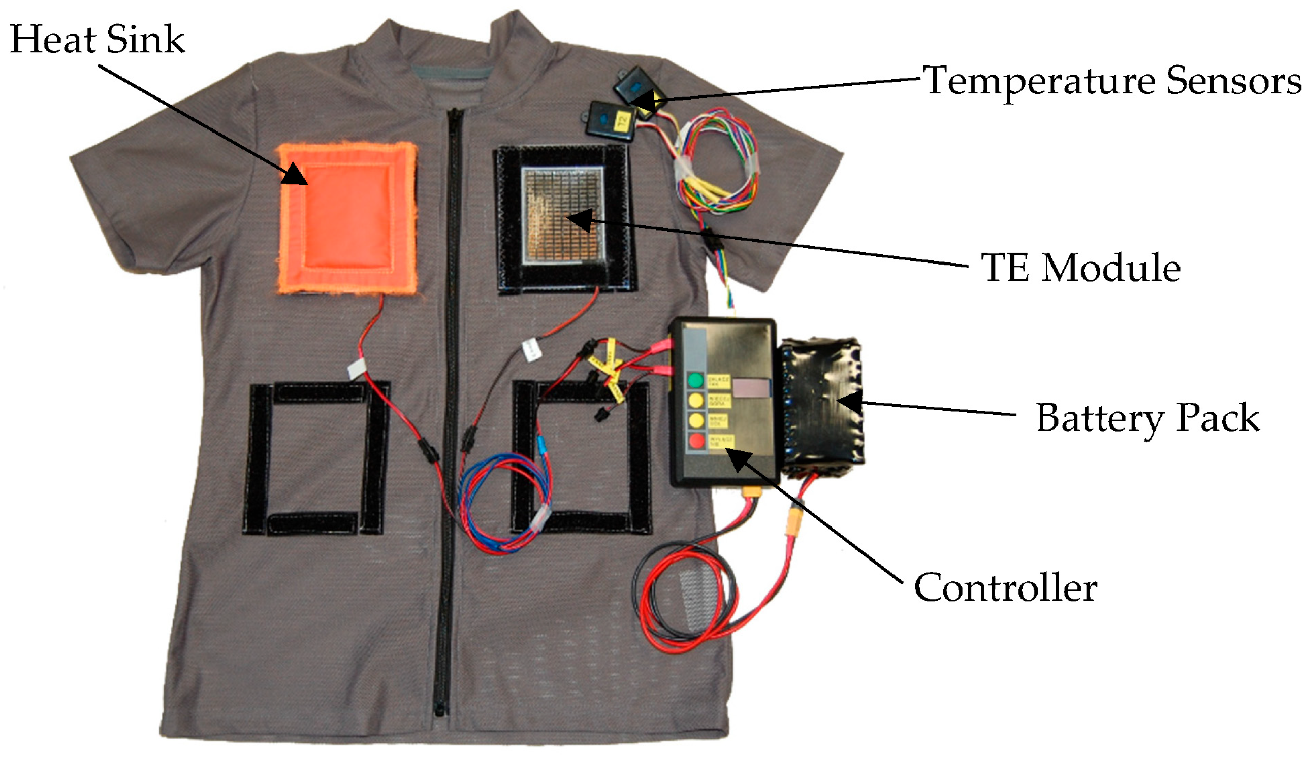
2.1. Tested Object

For the purpose of this study, a model of an active personal cooling system (PCS) based on TE modules was developed. The developed system consisted of seven TE modules, seven heat sinks, two temperature sensors, a power source and a dedicated electronic controller to regulate temperature through the electric power supplied to the TE modules. The TE modules were embedded into frames with Velcro that enabled their integration with custom-made clothing. Details related to the developed personal cooling system have been described in [11]. A view of the PCS with two TE modules and one heat sink mounted on the clothing showing the integration method is presented in Figure 1. In the utility tests, all seven TE modules and heat sinks were applied.
The dedicated power and temperature controller is an electronic system whose block diagram is shown in Figure 2. It consists of four main functional blocks: a power processing block, an input power measurement block, an output power measurement block and a microprocessor control block. The power source for the entire system is a rechargeable battery pack.
The power processing block includes analog-controlled DC/DC input switched-mode power converters (SMPCs) and digitally controlled output SMPCs. The input SMPCs provide appropriate supply voltages for all the controller blocks. The output SMPCs supply the TE modules. There are three output channels, each having its own, independently controlled output SMPC.
The input power measurement block includes a battery monitor circuit that measures the battery voltage and current and converts these results into a digital form. The task of the output power measurement block is to provide analog voltage signals proportional to the instantaneous voltage and current in each output channel.
A microcontroller in the microprocessor control block reads temperature data from temperature sensors and battery voltage and current from the input power measurement block via a serial digital interface. Moreover, the microcontroller’s internal analog-to-digital converter is used for converting analog measurement signals (output voltages and currents) to a digital form. The microcontroller’s program includes a control algorithm enabling the digital regulation of power or temperature, as described in Section 2.2. The output signals from the microcontroller are digital pulse width-modulated (PWM) signals whose duty cycles D[1..3] are controlled independently.
The microprocessor control block is also equipped with a user interface (a four-button keyboard for increasing or decreasing cooling intensity and navigating through a user menu and a display for presenting system settings and status) as well as an SD card interface for storing measurement data and controller configuration in a nonvolatile memory.

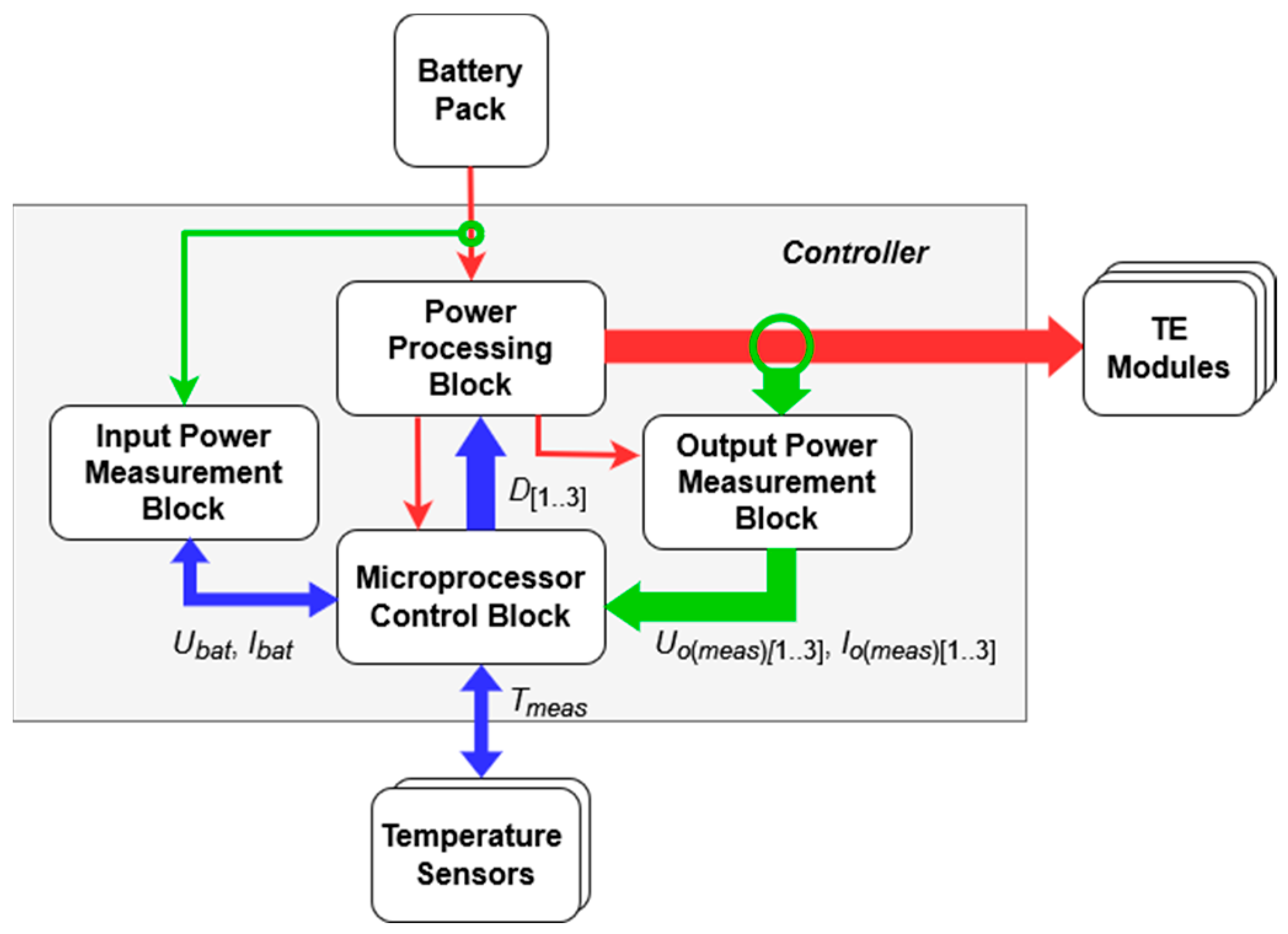
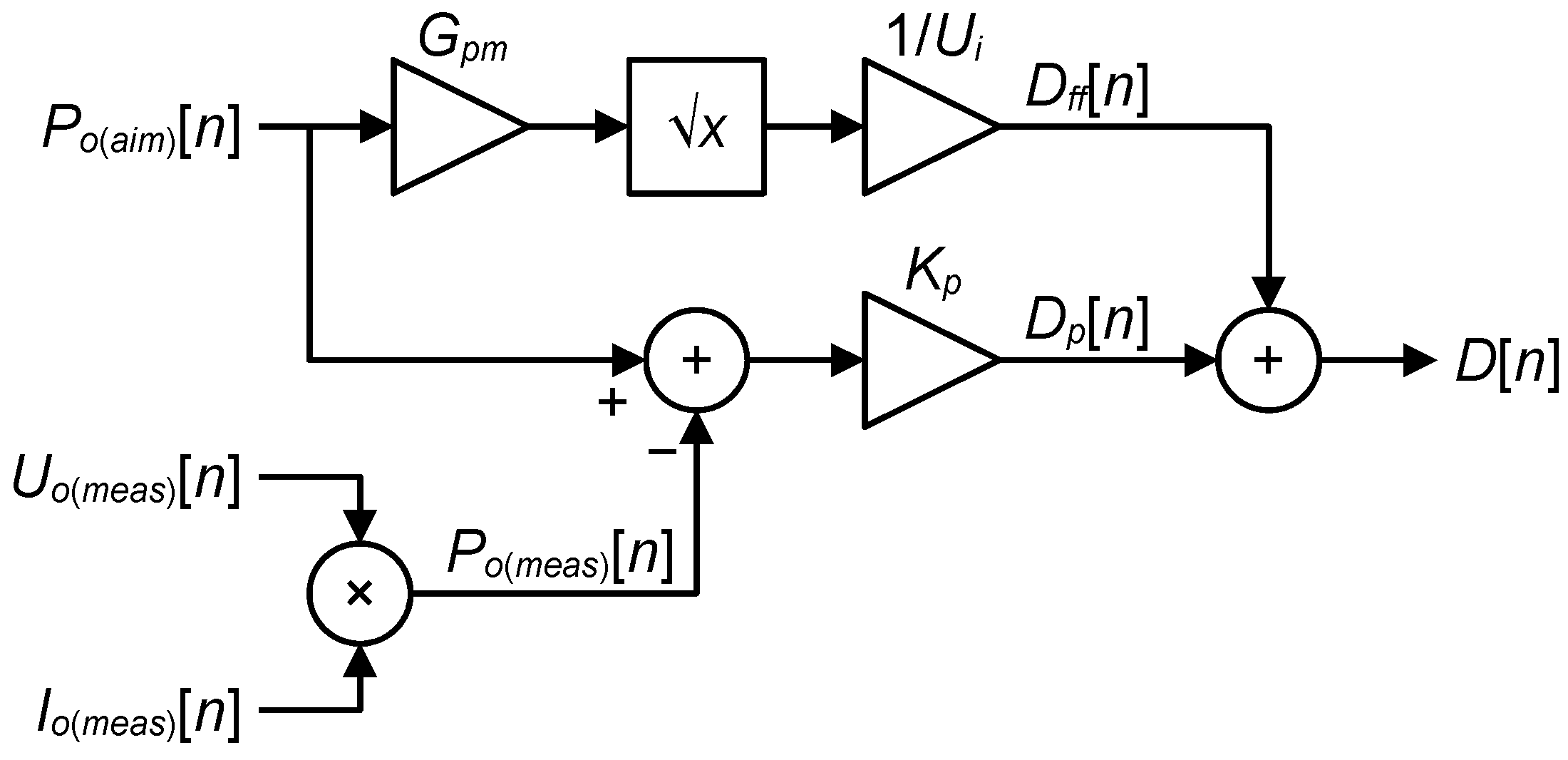
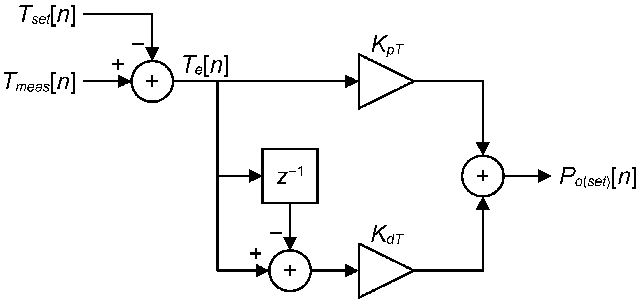
2.2. Digital Controller for Output SMPCs

The output power converters are automatically controlled so that the TE modules will provide the cooling intensity level set by the user. The system can operate in one of two modes, power regulation or temperature regulation, which are also selected by the user.
In the power regulation mode, the cooling intensity corresponds to the electric supply power of a single TE module Ppm(set). This setting is common for all the output converters and is used to determine the output power set point,
Po(set) = Npm Ppm(set),
where Npm is the number of TE modules supplied by the given converter. This set point is achieved using a digital proportional controller with feedforward implemented in the microcontroller. Its structure is presented in Figure 3.
The feedforward term is calculated from the ideal buck converter equation using the conductivity of the supplied TE modules Gpm and the input voltage of the output converters Ui, as described in detail in [11]:
Dff = (Po(aim) Gpm)1/2/Ui,
where Po(aim) is the aimed output power. In this equation, Ui is a constant parameter, as the output converters are supplied from one of the input SMPCs that delivers a regulated voltage of a constant value at its output. The conductivity Gpm is measured at the output of each converter when the controller is turned on. This is performed by briefly applying a low voltage and measuring the resulting current.
On the other hand, the feedback (proportional) term is calculated as
Dp = Kp Po(e),
where Kp is the proportional term coefficient and Po(e) is the output power error,
Po(e) = Po(aim)Po(meas).
The actual output power Po(meas) is calculated based on the measurement results of the given converter’s output voltage Uo(meas) and output current Io(meas):
Po(meas) = Uo(meas) Io(meas).
It must be noted that the aimed output power Po(aim) appearing in Equations (2) and (4) is not identical with the set output power Po(set). The aimed power is gradually changed up or down in constant steps until a new set power is reached. In this way, abrupt strikes of cold or warmth are avoided when Po(set) increases or decreases. On the other hand, the power should not change too slowly as this would make the user feel as if the system underperformed. The optimum stepping rate has been found empirically to be 400 ms.
The output of the power controller represents the duty cycle to be applied to its transistor switch. It is simply the sum of the feedforward and feedback terms:
D = Dff + Dp,
In the temperature regulation mode, the power controller still operates according to the same equations. However, the set output power Po(set), to which the input signal Po(aim) is stepped, is no longer directly coupled to the cooling intensity setting. Instead, it is derived by a higher-level temperature controller whose block diagram is shown in Figure 4.
PID controllers are often used for temperature control using TE modules, such as in box coolers [12]. However, as argued in [11], the proportional-derivative (PD) type is optimal for the considered application due to its following features:
  • Simplicity.
  • Inherent stability.
  • Ease of empirical term coefficient determination when plant parameters are unknown and variable (e.g., between users).
  • High reactivity to fast changes of the power setting or the temperature measured.
  • The corresponding controller equation is:
Po(set) = KpT Te[n] + KdT (Te[n] − Te[n − 1]),
where KpT and KdT are the proportional and derivative term coefficients, respectively, n is the current sample number and Te is the temperature error. The latter signal is calculated according to:
Te = TmeasTset,
where Tmeas is the temperature measured (an average of the readings from the two sensors) and Tset is the desired temperature set by the user.
It should be noted that although it is the set temperature that is subtracted from the measured one, the controller still implements a negative feedback scheme. This follows from the fact that the reaction of the input signal (temperature) is principally opposite to the change in the output signal (TE module supply power): when the electric supply power increases, heat is removed from the body more intensively, which makes the temperature decrease.

2.3. Testing Methodology

2.3.1. Research Conditions

This research was carried out at the Research and Demonstration Laboratory at the Central Institute for Labour Protection—National Research Institute, with the participation of a human tester. All tests were performed with the same participant so that results from different steps of the iterative testing and development process may be compared with each other. Tests were performed on different days at similar times. The participant was acquainted with the research methodology and signed an informed consent before starting the tests. The tests were carried out in a controlled environment where the temperature varied from 25 °C to 35 °C in steps of 5 °C. The relative humidity was constant at 65% and the air velocity was constant at 0 m/s.

2.3.2. Measured Parameters

During the experiments, thermal and electrical parameters were measured. Local skin temperature of the user was measured using AC1913-A sensors from Rotronic in two locations on the front of the body and on the back, with two sensors per location: one under a TE cooler and one beside the cooler. For the input (battery pack) voltage and current, the temperature was measured by either electronic sensor as well as the average of the two temperatures, the output voltage, the current and power of each TE module channel, the total output power of all TE module channels, the cooling level set by the user and the corresponding temperature or power.

2.3.3. Test Variants

An earlier research presented in [11] concentrated on the selection of the optimal system configuration in terms of ensuring high cooling efficiency while limiting the electric energy consumption. The following were demonstrated:
  • The best results were obtained using a control mode where the TE module supply power was alternatingly regulated by the controller described in Section 2.2, with a limit of 2 W, and brought down to a standby value of 1 W, with either phase duration of 1 min;
  • The optimum arrangement of TE modules was that with two modules on the front and five modules on the back.
These findings were applied in the present work, where laboratory tests were divided into two stages, as presented in Table 1. Stage I was aimed at the investigation of the effect of the active cooling using TE modules. The aim of stage II was to determine the influence of the ambient temperature. In stage I of the tests, two TE modules in the front were mounted on the upper chest, while in stage II of the tests, they were mounted on the abdomen, as preferred on the basis of the results from our previous research [9].

2.3.4. Testing Procedure

The clothing and the cooling system were acclimated in a separate air-conditioned room at a temperature of 23 °C for 1 h before the experiment in order to standardize study conditions. The participant stayed under the same conditions prior to the study. The conditions in the laboratory room were stabilized for 2 h.
Before starting the experiment, heat sinks were prepared by soaking them in water at a room temperature of 23 °C until their weight reached between 80 g and 90 g. At the same time, the TE modules were placed on the clothing in designated locations (depending on the stage of the study), which was then put on by the participant.
After soaking the heat sinks, they were attached to the TE modules using Velcro tapes. In order to achieve good adhesion of the TE modules to the skin, which is crucial for an efficient operation of the cooling system, the adherence of the clothing with PCS to the participant’s body was improved by means of an additional fastening system. During the experiment, the electronic controller together with the battery pack were placed in a kidney bag at the waist of the participant.
The tests were performed using a Zebris FDM-THM-M-3i inclinable treadmill by Zebris Medical GmbH. Each of the tests at stages I and II was composed of six phases, as shown in Table 2.

3. Results

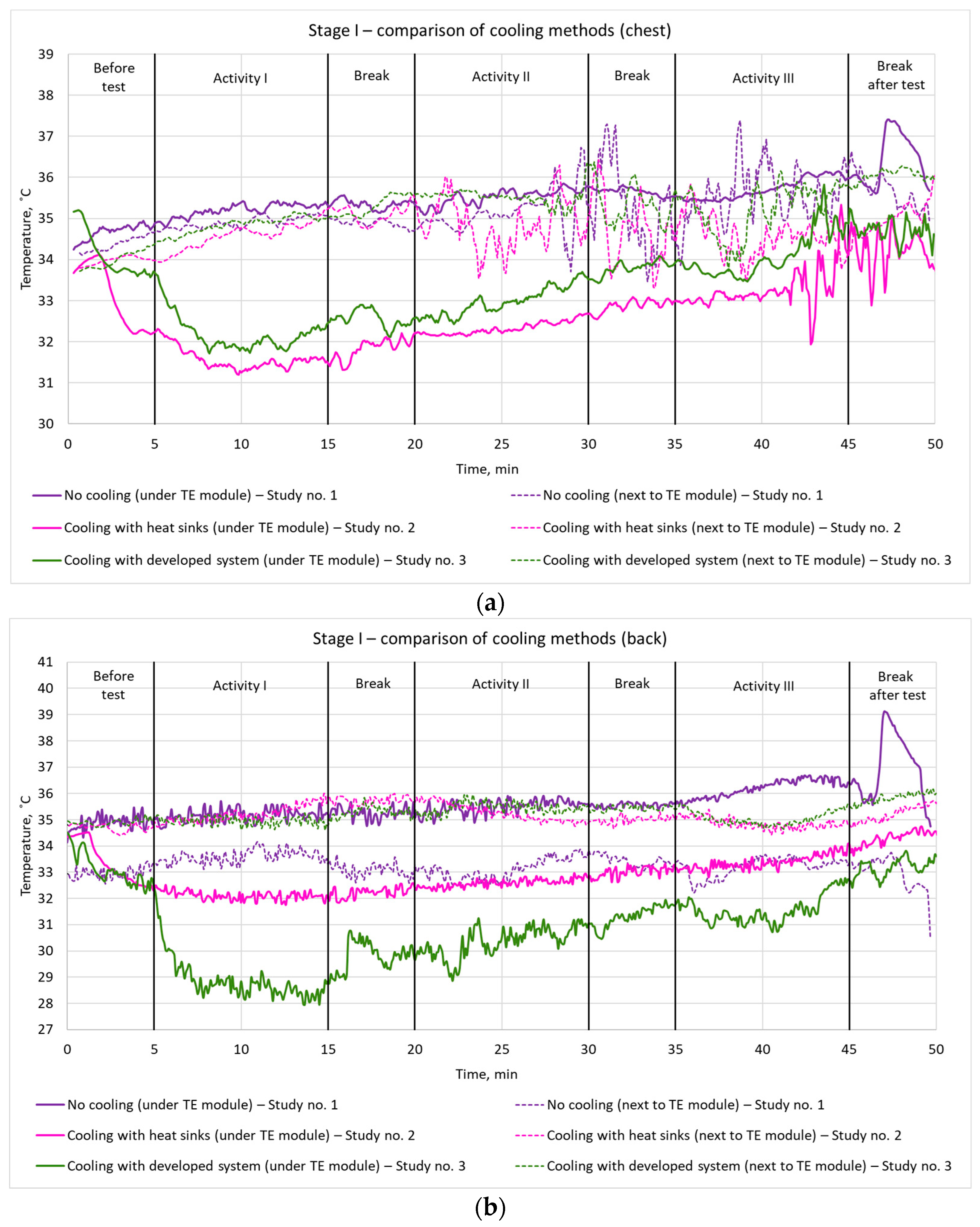
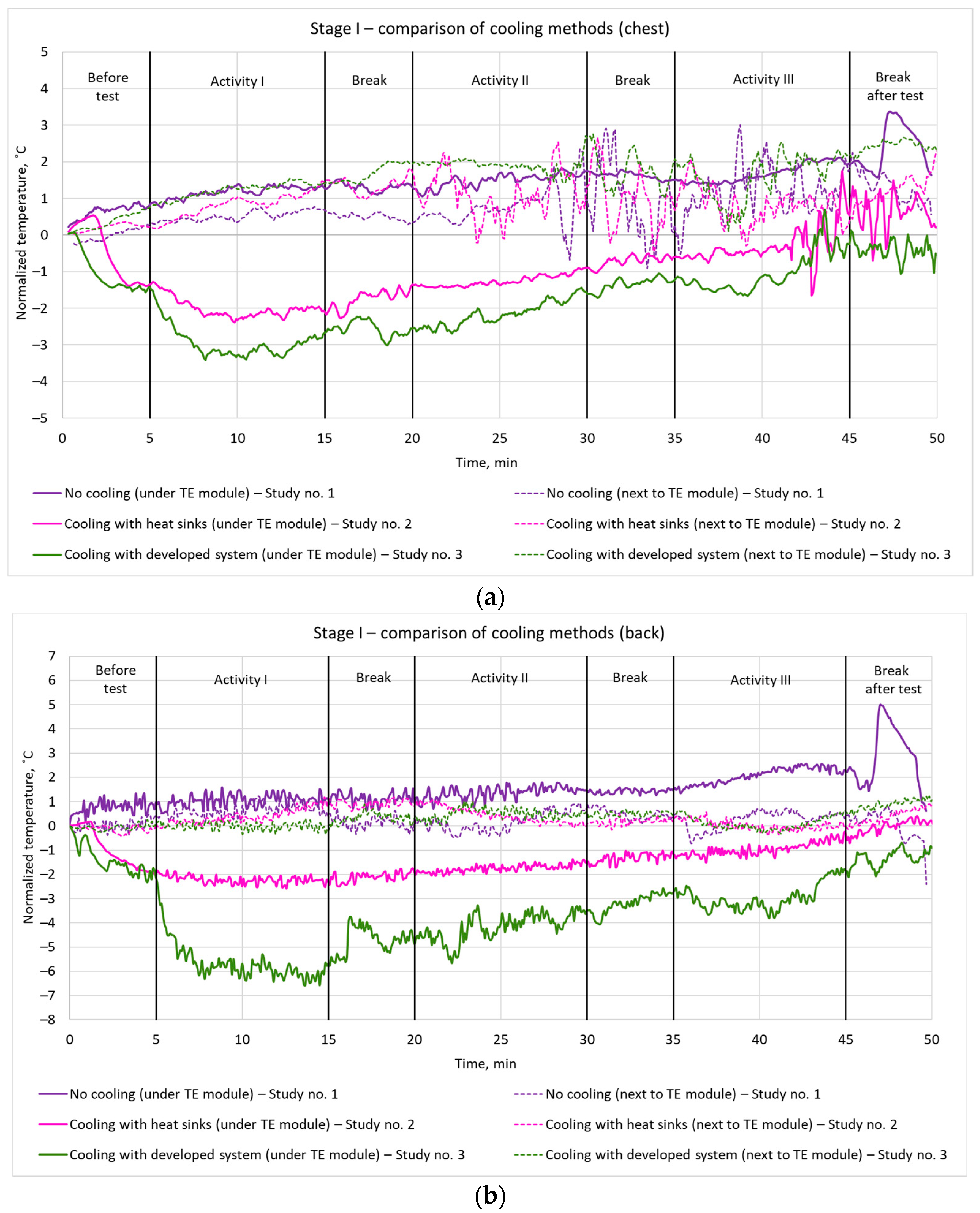
3.1. Effect of Active TE Modules on Cooling Efficiency (Stage I)

To assess the cooling efficiency of the developed system, local skin temperatures underneath and next to the TE modules were analyzed for the three cooling variants indicated in Table 1. Figure 5 and Figure 6 show the temperatures recorded on the chest (Figure 5a and Figure 6a) and on the shoulder blades (Figure 5b and Figure 6b).
A significant temperature drop before starting the test was observed for both Studies 2 and 3, resulting from the soaked heat sinks being mounted. However, the effect of activating the TE modules in the PCS was much more pronounced, as observed at the beginning of Activity I in Study 3.
For both cooling variants (Studies 2 and 3), lower local skin temperatures were observed throughout an entire experiment than in the case of a lack of cooling (Study 1). On the chest (Figure 5a), the local skin temperatures were similar for both cooling variants, while on the back (Figure 5b), the local skin temperature was reduced by 4 °C in Study 3 (TE modules active) in comparison to Study 2 (just soaked heat sinks mounted) and by 7 °C in comparison to Study 1 (no cooling). The differences mentioned apply to the beginning of the initial phase of the tests; they decreased by between 2 °C to 3 °C at the end of the tests.
On the chest (Figure 5a), a slightly lower temperature was observed with the TE modules off (Study 2) than when they were active (Study 3). However, this resulted just from a higher initial temperature in Study 3. The normalized temperature values shown in Figure 6a indicate that the cooling effect was in fact stronger with the TE modules on. In this latter case, the temperature drop was around 2 °C in the first 3 min of the test. On the back (Figure 6b), a greater drop in temperature was also observed with the TE modules active (Study 3). After 3 min from the start of cooling, a temperature drop of 4 °C was obtained under the TE module.
For all the tested variants, the measured temperatures increased throughout the entire period of the study. However, only with the TE modules active (Study 3), the temperature at the end of the test did not exceed the temperature measured at its beginning. This proves that active cooling using thermoelectric modules provides a more effective cooling than just using passive methods (soaked heat sinks).

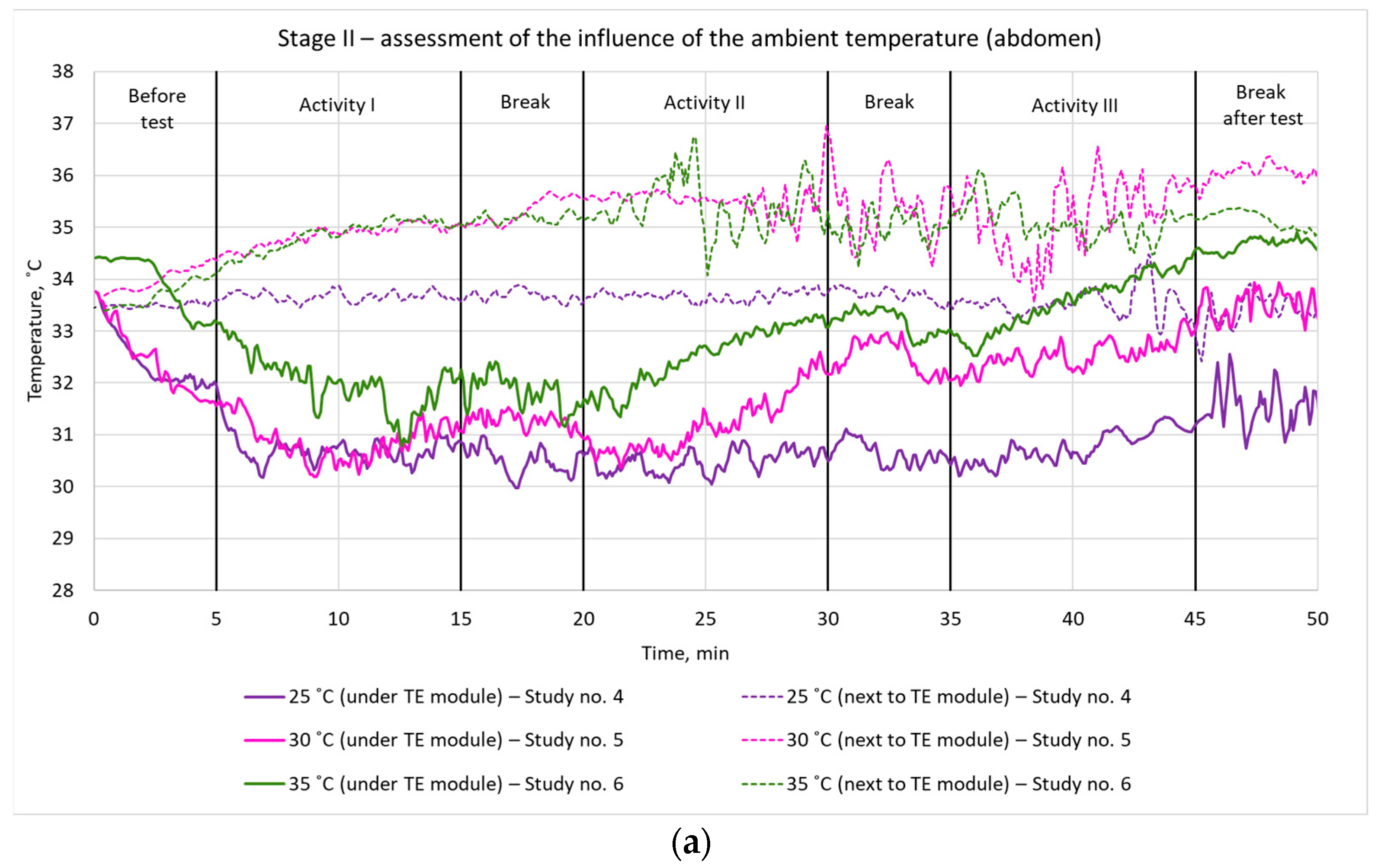
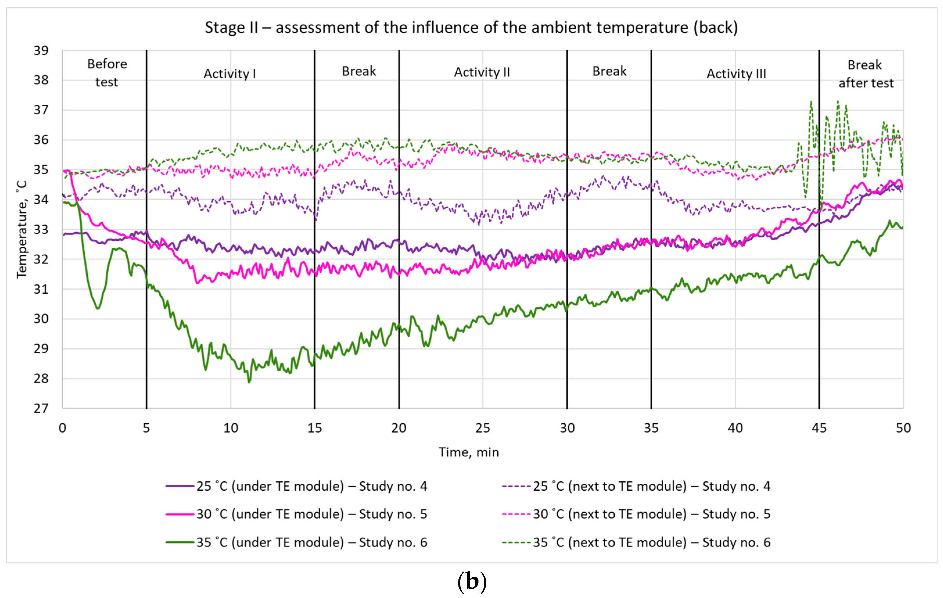
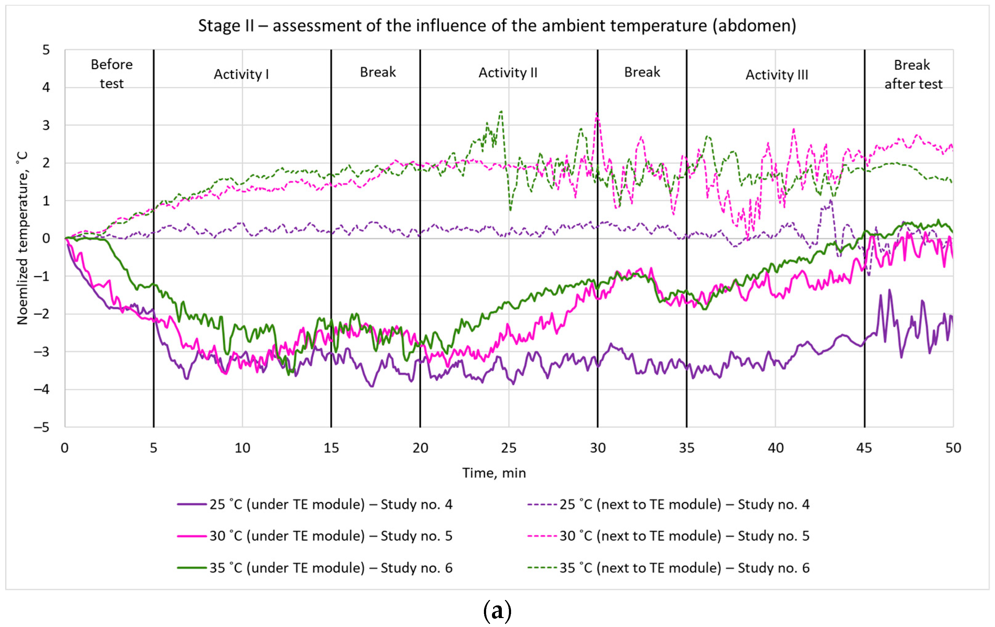
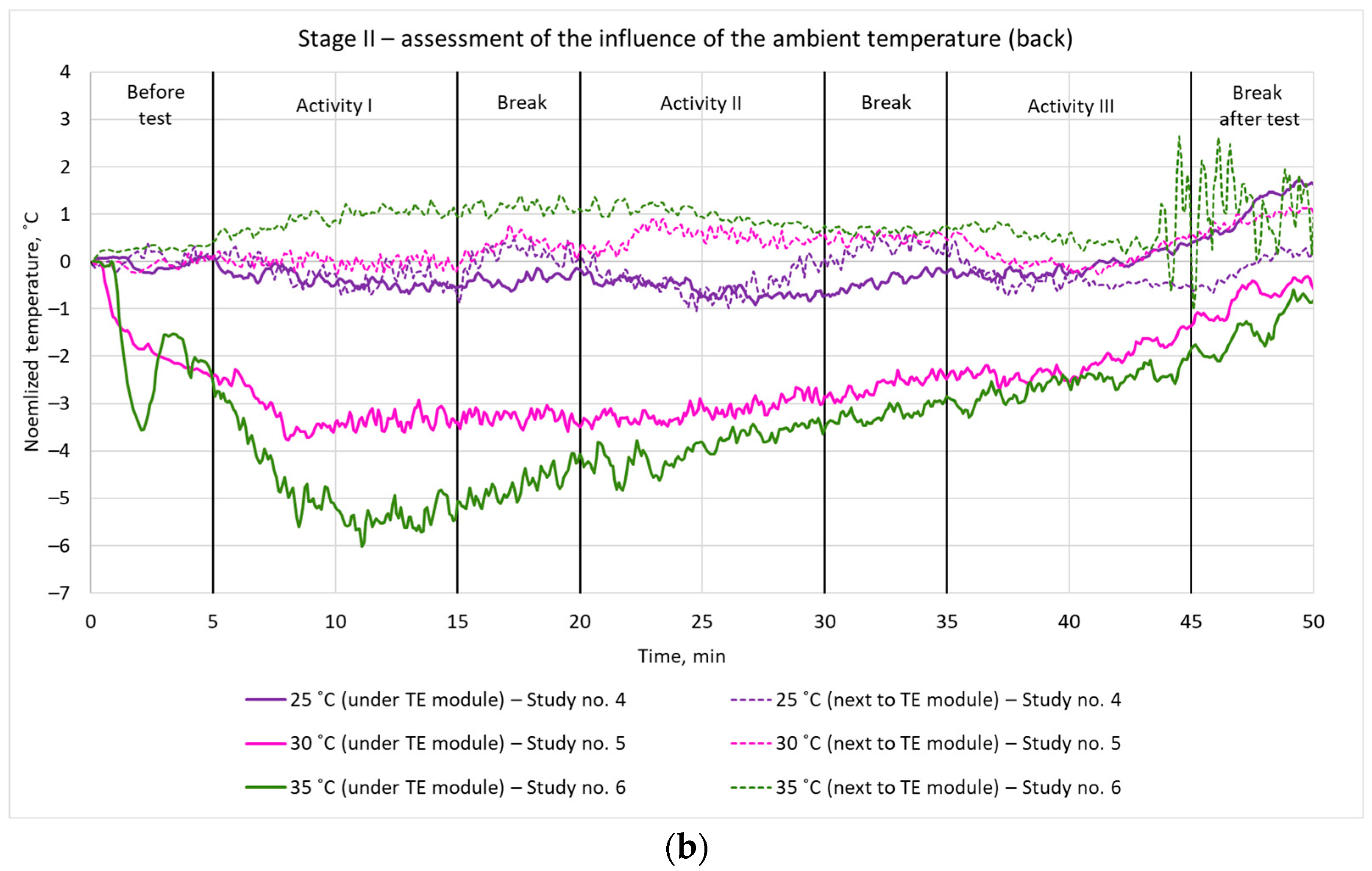
3.2. Effect of Ambient Temperature (Stage II)

At the next stage, the PCS with soaked heat sinks mounted and TE modules active was tested at three different ambient temperatures: 25 °C, 30 °C and 35 °C (Table 1). The measured skin temperatures are shown in Figure 7 and Figure 8.
A cooling effect was observed with the use of the developed system for all three ambient temperatures. The lowest local skin temperature, of around 28 °C, was measured on the back during Activity I at an ambient temperature of 35 °C (Figure 7b). In this case, it was about 6 °C lower than the body temperature before the test, which is a very pronounced difference (Figure 8b).
On the abdomen, the cooling effect was similar to that on the back for all ambient temperatures in the first phase of the study (Figure 7a). In further phases, the largest local skin temperature drop with respect to its initial value, amounting to 3.5 °C, was obtained for an ambient temperature of 25 °C (Figure 8a).
In every case, the local skin temperature increased with time. This was due to the high intensity of physical exertion.

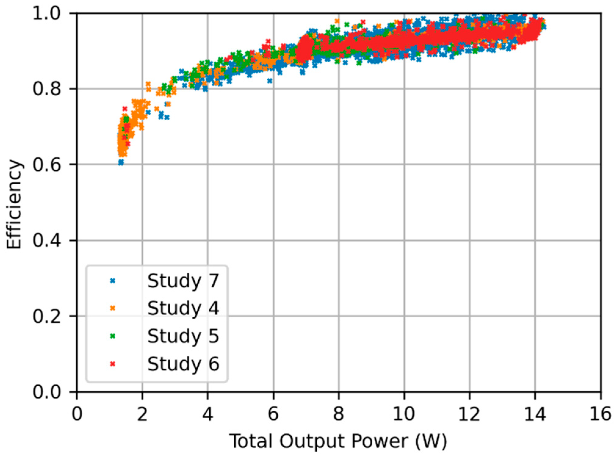
3.3. Power Consumption and Electronic Controller Efficiency

Table 3 contains the results related to electric power consumption and conversion in the system for Studies 4 through 7. They were therefore obtained for the same cooling variant (heat sinks mounted and TE modules active), while the ambient temperature varied. The durations of Studies 4 through 6 were almost equal (0.93 h to 0.94 h) while Study 7 was of a much longer duration (6.02 h). All the studies started with the battery fully charged.
It should be noted that the total output power recorded by the electronic controller is not exactly equal to the total electric supply power of the TE modules. This is due to the resistance of the connecting wires which was estimated to be approximately 0.27 Ω. This brings an additional power loss of 9.5% when two TE modules are supplied, whose equivalent resistance is 2.6 Ω. The possibility of reducing these losses is limited, due to the fact that any increase in the wire diameter decreases the comfort of the user.
On the other hand, power losses between the controller and the battery are negligible thanks to the much shorter distance, greater wire diameter and lower current (resulting from a higher converter input voltage as compared to its output one). Thus, the input voltage is, to a good approximation, equal to the battery voltage.
On the basis of the measurement results contained in Table 3, the battery power was calculated for each sample as
Pbat[n] = Ui[n] × Ii[n].
where Ui is the controller’s input voltage, Ii is its input current and n is the sample number. Then, the energy drawn from the battery and the energy delivered to the converter’s output were evaluated according to, respectively,
Wbat = ∑ [Pbat [n] × (t[n] − t[n − 1])],
Wo,tot = ∑ [Po,tot[n] × (t[n] − t[n − 1])].
where Po,tot is the recorded controller’s total output power and t is the sample time stamp. Consequently, the respective average powers were
Pbat(av) = Wbat/∆tstudy,
Po,tot(av) = Wo,tot/∆tstudy,
where ∆tstudy is the study duration.
Finally, the average power conversion efficiency of the electronic controller was evaluated as
η = Po,tot(av)/Pbat(av).
This overall average electronic controller efficiency includes both power losses in all the power converters and power consumption by the microcontroller, the display and auxiliary circuitry.
To investigate the effect of varying operating conditions of the controller, an instantaneous efficiency was also evaluated for the consecutive samples using the following formula:
η[n] = Po,tot[n]/Pbat[n].
In this case, only those time intervals were taken into account where neither the battery nor the output power varied, applying a limit of 5% variation sample-to-sample. This was because the reaction at the input of the controller (battery current) is delayed with respect to the output power, this resulting from the dynamic characteristics of switch-mode power converters [13]. Consequently, the result of Equation (15) is only physically meaningful in a steady state. The obtained overall instantaneous efficiency has been plotted in Figure 9 as a function of the total output power Po,tot. It can be seen that the characteristic obtained does not depend on a particular study, thus on ambient temperature or test duration.

4. Discussion

4.1. Cooling Efficiency

The results of the study confirm that the developed PCS based on TE modules is able to provide efficient cooling with a temperature drop of about 3.5 °C. This result is coherent with the results obtained by Hong et al. [9] who also worked on the implementation of flexible TE modules in PCS; however, their solution was not intended for physical workers.
According to our observations, cooling efficiency of the PCS with TE modules and evaporative heat sinks is highly dependent on both the heat capacity and the rate of water evaporation from the heat sink, as well as on the fitting of the TE module to the user’s body. The large temperature drop prior to the beginning of the test results from the temperature of the water absorbed by the heat sink being lower than the hot side of the TE module. When the temperature of the water and that of the TE module’s hot side become equal, the cooling efficiency is decreased. Nevertheless, even then the evaporation of water from the soaked heat sink still provides a cooling effect whose intensity is stable in time. Following Cotter et al. [14], local cooling of about (−4) °C can be considered as mild, and the results obtained with our TE-based PCS were quite similar to the effect provided by the personal liquid cooling vest described by Xu et al. [15] and are within the range of reduction of the local skin temperature (from 1.1 to 7.4 °C) achieved by Song and Wang [16] by means of PCS with PCMs and small air ventilation fans.
The obtained results also indicate the importance of a proper fitting of the TE modules to the user’s body. While all modules were supplied with nearly the same electric power, differences are observed between the modules in the resulting local skin temperature. The particular design of the clothing enables better fitting of those TE modules that are located on the back. That is why a stronger cooling effect is observed there than on the chest.
Without any cooling (no heat sinks and TE modules turned off), temperatures under TE modules are slightly higher than those next to them throughout the entire test duration, both on the chest and on the back. This is caused by the presence of an additional layer—a TE module—at the place of measurement. As the blouse’s material was highly air-permeable, this resulted in lower temperatures outside the TE modules. The research outcomes in the above-discussed field related to the influence of water evaporation from the flexible heat sinks in the TE-based PCS as well as the fitting of the TE modules to the human body on the PCS cooling efficiency have not been considered up to now. Therefore, they indicate a completely new research direction in environmental engineering that will be explored further.

4.2. Energy Consumption and Operating Time

As it can be seen in Table 3, the peak power drawn from the battery is about 15 W for any study. This value results from the power limitation of 2 W per TE module that is activated each time the temperature controller requests a maximum module supply power.
On the other hand, both the average battery power and the average output power rise with the ambient temperature increasing. This is expected as more heat has to be evacuated from the body in order to maintain a comfortable body temperature, which in turn requires a higher temperature difference to be produced between the ambient temperature and the body. The average battery power has increased by 42% with the ambient temperature rising from 25 °C to 35 °C. This is a very pronounced change, affecting the required capacity of the battery and, consequently, the size, weight and cost of the latter.
The average output power is higher in Study 7 than in Study 5 despite the ambient temperature being the same. This may result from the efficacy of heat sinks decreasing over the long-time scale due to evaporation of water therefrom. To compensate for this, the electric supply power of the TE modules must be increased.
Based on the average battery power of 9.45 W obtained for the long-time study, a battery with a capacity of 10.2 Ah and a nominal voltage of 3.7 V (lithium-ion technology) is sufficient to supply the system for 4 h, which corresponds to a standard power bank whose weight is typically about 230 g. A battery of 20.4 Ah would be required to extend the operating time to 8 h.
In papers where similar wearable cooling systems have been described, power consumption is rarely analyzed. In [17], the ambient temperature varied between 27 °C and 35 °C, while the power consumption was between 10 W and 15 W, which is higher than for the system presented here (supposing that the value of 10 W corresponded to 27 °C, the difference may be estimated by linear interpolation as 31%). This may have resulted from the use of a fan and a water pump which additionally contributed to the overall weight of 680 g for an operating time of only 2 h. The total weight of the system presented in this paper is similar at 650 g with a battery of 3.4 Ah and 18.2 V (nominal values), allowing it to operate for 6.4 h (3.2 times longer) under the worst-case temperature of 35 °C.
The body temperature regulator described in [18] consumed 5.58 W (0.05 W in standby) with just a single TE module versus seven modules in this work. However, it seems that that system was not tested on humans, so the practical effect of this supply power on body temperature is unknown.
The electric energy conversion efficiency of the developed dedicated electronic controller was high. According to Table 3, its average value over an entire study, as defined by Equation (14), was 0.89 to 0.92. This efficiency decreased with decreasing output power. This effect can be seen more clearly in Figure 9, where the instantaneous efficiency has been plotted, as defined by Equation (15). It may be explained by an important contribution of those components of the power consumption that are independent of or weakly dependent on the output power, such as the supply power of the control circuitry, especially the microcontroller, the display and the SD card.
For high output power, those components become dominant that depend on the output current, including losses in power converters’ components, e.g., transistors and inductors. As these losses have been minimized by careful component selection, the efficiency then reaches 0.95, which is identical with the result given in [17]. The nature of the relationship observed is favorable for a battery-supplied system, as it keeps the absolute power loss low: the efficiency is high when the output power is high, and it is only low when the output power is low as well.
It should be noted that much of the control circuitry power consumption is due to those functions that were necessary for research purposes, such as the OLED display, the SD card and the battery monitor. These features may be eliminated in a final version of the system, thus increasing the overall efficiency and reducing the energy drawn from the battery.

5. Conclusions

The laboratory tests of the developed personal cooling system carried out with human participation allowed the efficiency of active cooling using TE modules to be compared to passive cooling using only soaked heat sinks. They also made it possible to investigate the effect of the ambient temperature. The use of TE modules provided an efficient reduction of the skin temperature during an entire experiment of about 1 to 6 h involving moderate physical intensity.
It follows from the results obtained that a proper fitting of the clothing to the user’s silhouette is required to efficiently draw the excess heat out of the human body. With those TE modules that better adhere to the body, a much higher temperature difference can be achieved. Moreover, in the first stage of the research, we proved a favorable effect of the use of evaporative heat sinks (Study 2) as well as a synergic effect of the use of TE modules with those heat sinks (Study 3). Furthermore, without effectively drawing heat from the hot side of the TE modules, they will not provide an expected cooling function. The tests conducted in different ambient temperatures show similar differences in local skin temperature between cooled and uncooled locations. This suggests that ambient temperature has no significant effect on the cooling efficiency of the proposed PCS, at least in the range between 25 °C and 35 °C.
The experimental results demonstrate that power losses in the power electronic converters are relatively low, enabling an average efficiency of 0.90 and a maximum one of 0.95 (for a maximum TE module electric power), which is the same as in a similar system. On the other hand, the overall electronic controller efficiency includes the power consumption by the control circuitry that becomes more prominent at low output power values, leading to a decrease in the efficiency. However, much of this consumption is related to functions that were only implemented for research purposes and may be eliminated in a future version of the system to decrease the power demand. This will allow the battery size and weight to be reduced or the operating time to be increased.
The research stage described in the present paper was focused on the cooling efficiency and energy efficiency aspects of system operation. The conclusions from this research will be used in the development of an improved PCS prototype. The main limitations of the performed tests are related to the involvement of only one participant. Nevertheless, this has been sufficient to reliably assess the PCS in respect of its cooling performance and power consumption thanks to a repeatable testing methodology adopted. To formulate wider conclusions related to the evaluation of PCS efficiency, it is planned to test the prototype with multiple end users. Those further tests will involve workers carrying out physical operations characteristic for their real workplaces. This will enable us to study the ease of use, ergonomics as well as functionality of the developed PCS and its compatibility with other equipment used during routine work. Moreover, based on further experiments, a decision on a potential limitation of the number of TE modules will be made to make PCS more cost-effective and increase its potential for successful placement on the market.

Author Contributions

Conceptualization, A.D.; data curation, A.D., M.K., Ł.S. and B.P.; investigation, A.D., M.K., Ł.S. and B.P.; methodology, A.D.; resources, A.D.; supervision, A.D.; validation, A.D., M.K., Ł.S. and B.P.; visualization, M.K., Ł.S. and B.P.; writing—original draft, A.D., M.K., Ł.S. and B.P.; writing—review and editing, A.D., M.K., Ł.S. and B.P. All authors have read and agreed to the published version of the manuscript.

Funding

This paper is published and based on the results of a research task carried out within the scope of the fifth stage of the National Programme “Improvement of safety and working conditions” supported from the resources of the National Centre for Research and Development (task no. III.PB.09), entitled “Development of the protective clothing with an active cooling function based on the thermoelectric effect (Peltier modules)”. The Central Institute for Labour Protection—National Research Institute is the Programme’s main coordinator.

Institutional Review Board Statement

Not applicable.

Informed Consent Statement

An informed consent statement was signed by the participant involved in the laboratory tests.

Data Availability Statement

The data presented in this study are available on request from the corresponding author.

Conflicts of Interest

The authors declare no conflict of interest.

References

  1. Council of the European Union. Council Directive 89/391/EEC of 12 June 1989 on the Introduction of Measures to Encourage Improvements in the Safety and Health of Workers at Work; Council of the European Union: Brussels, Belgium, 1989. [Google Scholar]
  2. Sajjad, U.; Hamid, K.; Rehman, T.U.; Sultan, M.; Abbas, N.; Ali, H.M.; Imran, M.; Muneeshwaran, M.; Chang, J.-Y.; Wang, C.-C. Personal thermal management—A review on strategies, progress, and prospects. Int. Commun. Heat Mass Transf. 2022, 130, 105739. [Google Scholar] [CrossRef]
  3. Al Sayed, C.; Vinches, L.; Dupuy, O.; Douzi, W.; Dugue, B.; Hallé, S. Air/CO2 cooling garment: Description and benefits of use for subjects exposed to a hot and humid climate during physical activities. Int. J. Min. Sci. Technol. 2019, 29, 899–903. [Google Scholar] [CrossRef]
  4. Bartkowiak, G.; Dabrowska, A.; Marszalek, A. Assessment of an active liquid cooling garment intended for use in a hot environment. Appl. Ergon. 2017, 58, 182–189. [Google Scholar] [CrossRef] [PubMed]
  5. Lu, Y.; Wei, F.; Lai, D.; Shi, W.; Wang, F.; Gao, C.; Song, G. A novel personal cooling system (PCS) incorporated with phase change materials (PCMs) and ventilation fans: An investigation on its cooling efficiency. Therm. Biol. 2015, 52, 137–146. [Google Scholar] [CrossRef] [PubMed]
  6. Qiao, Y.; Cao, T.; Muehlbauer, J.; Hwang, Y.; Radermacher, R. Experimental study of a personal cooling system integrated with phase change material. Appl. Therm. Eng. 2020, 170, 115026. [Google Scholar] [CrossRef]
  7. Ding, J.; Zhao, W.; Jin, W.; Di, C.; Zhu, D. Advanced Thermoelectric Materials for Flexible Cooling Application. Adv. Funct. Mater. 2021, 31, 2010695. [Google Scholar] [CrossRef]
  8. Wei, H.; Zhang, J.; Han, Y.; Xu, D. Soft-covered wearable thermoelectric device for body heat harvesting and on-skin cooling. Appl. Energy 2022, 326, 119941. [Google Scholar] [CrossRef]
  9. Hong, S.; Gu, Y.; Seo, J.K.; Wang, J.; Liu, P.; Meng, Y.S.; Xu, S.; Chen, R. Wearable thermoelectrics for personalized thermoregulation. Sci. Adv. 2019, 5, eaaw0536. [Google Scholar] [CrossRef] [PubMed] [Green Version]
  10. Li, Z.; Zhang, M.; Yuan, T.; Wang, Q.; Hu, P.; Xu, Y. New wearable thermoelectric cooling garment for relieving the thermal stress of body in high temperature environments. Energy Build. 2023, 278, 112600. [Google Scholar] [CrossRef]
  11. Dąbrowska, A.; Kobus, M.; Starzak, Ł.; Pękosławski, B. Analysis of Efficiency of Thermoelectric Personal Cooling System Based on Utility Tests. Materials 2022, 15, 1115. [Google Scholar] [CrossRef] [PubMed]
  12. Firdaus, A.Z.A.; Zolkifly, M.Z.; Syahirah, K.N.; Normahira, M.; Aqmariah, S.N.; Ismail, I.I. Design and development of controller for Thermoelectric cooler system. In Proceedings of the 2015 IEEE International Conference on Control System, Computing and Engineering (ICCSCE), Penang, Malaysia, 27–29 November 2015; pp. 264–268. [Google Scholar] [CrossRef]
  13. Maniktala, S. Switching Power Supplies A–Z, 2nd ed.; Newnes: Oxford, UK, 2012. [Google Scholar] [CrossRef]
  14. Cotter, J.D.; Taylor, N.A.S. The distribution of cutaneous sudomotor and alliesthesial thermosensitivity in mildly heat-stressed humans: An open-loop approach. J. Physiol. 2005, 565 Pt 1, 335–345. [Google Scholar] [CrossRef] [PubMed]
  15. Xu, J.; Chen, G.; Wang, X.; Chen, Z.; Wang, J.; Lu, Y. Novel Design of a Personal Liquid Cooling Vest for Improving the Thermal Comfort of Pilots Working in Hot Environments. Indoor Air 2023, 2023, e6666182. [Google Scholar] [CrossRef]
  16. Song, W.; Wang, F. The hybrid personal cooling system (PCS) could effectively reduce the heat strain while exercising in a hot and moderate humid environment. Ergonomics 2016, 59, 1009–1018. [Google Scholar] [CrossRef] [PubMed]
  17. Itao, K.; Hosaka, H.; Kittaka, K.; Takahashi, M.; Lopez, G. Wearable Equipment Development for Individually Adaptive Temperature-conditioning. J. Jpn. Soc. Precis. Eng. 2016, 82, 919–924. [Google Scholar] [CrossRef] [Green Version]
  18. Chen, Y.-S.; Chuang, Y.-R.; Chiang, H.-H.; Chen, Y.-L. The Design of an Automatic Body Temperature Regulator. In Proceedings of the 2019 IEEE International Conference on Consumer Electronics—Taiwan (ICCE-TW), Yilan, Taiwan, 20–22 May 2019; pp. 1–2. [Google Scholar] [CrossRef]
Figure 1. View of the tested system presenting TE module and heat sink integration with clothing.
Energies 16 04699 g001
Figure 2. Block diagram of the dedicated power and temperature controller (digital signals—blue, analog signals—green, power paths—red).
Energies 16 04699 g002
Figure 3. Block diagram of the digital power controller.
Energies 16 04699 g003
Figure 4. Block diagram of the digital temperature controller.
Energies 16 04699 g004
Figure 5. Local skin temperature under and next to a TE module for different cooling variants (stage I, study numbering compliant with Table 1): (a) chest; (b) back.
Energies 16 04699 g005
Figure 6. Normalized local skin temperature for different cooling variants (stage I, study numbering compliant with Table 1): (a) chest; (b) back.
Energies 16 04699 g006
Figure 7. Local skin temperature under and next to a TE module for different ambient temperatures (stage II, study numbering compliant with Table 1): (a) abdomen; (b) back.
Energies 16 04699 g007aEnergies 16 04699 g007b
Figure 8. Normalized local skin temperature under and next to a TE module for different ambient temperatures (stage II, study numbering compliant with Table 1): (a) abdomen; (b) back.
Energies 16 04699 g008aEnergies 16 04699 g008b
Figure 9. Overall instantaneous efficiency of the electronic controller as a function of its total output power (study numbering as in Table 1).
Energies 16 04699 g009
Table 1. Study stages and related experiment conditions.
StageStudyHeat SinksTE ModulesAmbient
Temperature
I1NoneOff30 °C
2MountedOff30 °C
3MountedActive30 °C
II4MountedActive25 °C
5MountedActive30 °C
6MountedActive35 °C
Table 2. Test phases at stages I and II.
PhaseActivityMovement KindMovement SpeedTrack Inclination
aIWalk3 km/h0%
bBreakNoneN/AN/A
cIIWalk5 km/h0%
dBreakNoneN/AN/A
eIIIWalk5 km/h10%
fBreakNoneN/AN/A
Table 3. Electric power delivered to the TE modules and power drawn from the battery (study numbering as in Table 1).
StudyAmbient Temperature
(°C)
Study Duration
(h)
Average Battery Voltage
(V)
Peak Battery Discharge Power
(W)
Total Output Energy
(Wh)
Total Energy Drawn from Battery
(Wh)
Average Total Output Power
(W)
Average Battery Discharge Power
(W)
Average Controller Efficiency
4250.9320.5414.95.686.366.096.830.89
5300.9320.5514.97.468.178.058.820.91
6350.9420.5015.18.429.138.939.670.92
7306.0219.6614.952.1556.848.679.450.92
Disclaimer/Publisher’s Note: The statements, opinions and data contained in all publications are solely those of the individual author(s) and contributor(s) and not of MDPI and/or the editor(s). MDPI and/or the editor(s) disclaim responsibility for any injury to people or property resulting from any ideas, methods, instructions or products referred to in the content.

