
Variation of Mean Radiant Temperature in Rooms for Summer and Winter Conditions
Department of Building, Energy and Material Technology, UiT—The Arctic University of Norway, 8515 Narvik, Norway
*
Author to whom correspondence should be addressed.
Energies 2023, 16(15), 5609; https://0-doi-org.brum.beds.ac.uk/10.3390/en16155609
Submission received: 24 May 2023
/
Revised: 13 July 2023
/
Accepted: 19 July 2023
/
Published: 25 July 2023
(This article belongs to the Special Issue Performance Evaluation, Thermal Comfort and Energy Efficiency in Buildings)
Abstract
:The standard for ergonomics of the thermal environment provides information on the calculation of optimal thermal comfort. Operative temperature (OT) is one of the essential elements of thermal comfort and is a function of air temperature, mean radiant temperature (MRT), and air velocity. This paper investigates the impact of diverse influences on MRT in an office room based on occupant position and posture (seated and standing). A comparative simulation study of the varied thermal transmittance (U-value) of the only external wall with a window in an office room depending on the wide-ranging outdoor temperature is conducted in the MATLAB tool Simulink. The air temperature and air velocity are assumed according to the standards, and the MRT is simulated. The angle factors, U-value of walls/windows, occupant position, occupant posture, and outdoor temperature are the critical parameters that affect MRT. The results show varied responses from MRT for each of the five outdoor temperature scenarios simulated for three types of exterior walls. Seated occupants have equal MRT, whereas standing occupants have minor discrepancies when exposed to a window at the same distance in all outdoor scenarios. When the placement of occupants is not equally exposed to the window, the seated occupants have a higher MRT difference than the standing occupants.
1. Introduction
The definition of thermal comfort states “the state of mind that expresses satisfaction with the thermal environment” [1]. Six parameters affect thermal comfort and are classified as environmental parameters and personal parameters. The environmental parameters are air temperature (), mean radiant temperature (MRT, ), air velocity, and relative humidity, whereas the personal parameters are metabolic rate and clothing insulation. However, the ergonomic standard in a thermal environment [2] shows that the desired optimum thermal environment of a room can be achieved with a permissible operative temperature range depending on personal parameters. Operative temperature (OT, ) is the “uniform temperature of an imaginary black enclosure in which an occupant exchanges the same amount of heat by radiation and convection as in the actual non-uniform environment” [2]. In a simplified measure, OT can be calculated as the mean value of and , when in an indoor environment, the air velocity is below 0.2 m/s and the difference between and is less than 4 °C.
Equation (1) shows that both and contribute equally to indoor thermal comfort. Air temperature is the temperature of the air around the occupant that can be measured by a mercury thermometer, thermocouple, or thermistor [3,4]. MRT is the “uniform temperature of an imaginary enclosure in which radiant heat transfer from the human body equals the radiant heat transfer in the actual non-uniform enclosure” [5]. MRT can be calculated from the surface temperature () of the surrounding surfaces and the angle factor () between a person and the surrounding surfaces as follows:
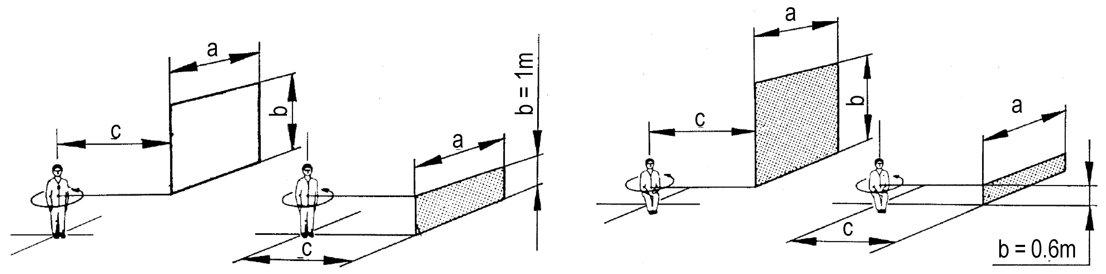
The angle factor for the human body, also known as the view factor, is the radiation of heat exchange between the person and the environment [3]. The ISO 7726 standard [5] provides a simple angle factor calculation method for each surface of a rectangular/square room depending upon the person’s position and posture. The iterative calculation process involves computing twenty-four sections based on six surfaces (walls, floor, and ceiling) that are divided into four sections each. For each section of the surface, surface elements a, b, and c are measured depending upon the location of the person and the room dimension (Figure 1). The angle factor () is obtained from Equations (3) and (4) and Table 1 [5].
There have been studies on radiative heat transfer prediction based on the position and posture of the human body [6,7,8,9]. Most of the studies analyze angle factors and room temperature dynamics in rectangular spaces and limit the human position to the center of the room in a seated posture [10,11,12,13]. For calculation of the angle factor, surface elements a, b, c and elements from Equations (3) and (4) that are Fmax, A, B, C, D, and E are required.
All the surface elements a, b and c vary depending upon which section of the wall is taken into consideration for vertical and horizontal surfaces, as shown in Table 1. The surface element b is different for seated and standing posture. For seated posture, the element b for vertical surfaces in the lower sections is 0.6 m, whereas for standing posture, it is 1 m, as shown in Figure 1. There have been subsequent studies on the determination of MRT from the calculation of angle factors [14,15,16,17].
The thermal transmittance (U-value) measures the heat flow through a building component by conduction, convection, and radiation and is determined by the thermal values of the heat conductivity and thickness of the building component. represents the total thermal resistance for all the material layers of the wall, including indoor heat transfer coefficient () and outdoor heat transfer coefficient (), as shown in Equation (5). The U-value of a wall can be found in Equation (6). The average values of the and are 0.13 and 0.04 m2k/W, respectively [18].
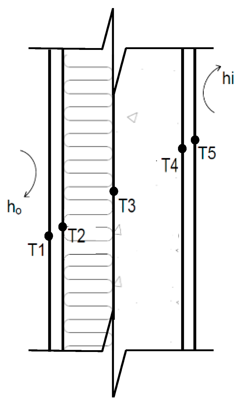
The heat loss/gain from a surface is dependent on the temperature difference between two surfaces. Figure 2 shows a simple wall with concrete, insulation, and exterior and interior finishes. The temperature at each material layer is termed T1, T2, T3, T4, and T5 from outdoor to indoor. Equation (9) expresses the heat loss/gain of a wall depending on the temperature variation from indoors to outdoors [19].
Based on the heat balances, the temperature on the inner surface can be calculated:
Equation (10) is a simple wall equation with temperature damping, where T5 is equivalent to the indoor surface temperature (Tsi) of the respective walls and windows. The U-value makes a major difference in temperature between indoors and outdoors. In Norway, the Norwegian Building Technical Regulations (TEK) for construction works provide the maximum allowed U-value for buildings (Table 2) and have been updating the U-value since 1987 in accordance with the Planning and Building Act to minimize energy use.
The aim of the study is to investigate the impact of altering outdoor temperatures and the thermal transmittance of the wall on the indoor thermal environment and check whether the optimal MRT/OT according to ergonomic standards is achieved.
2. Materials and Methods
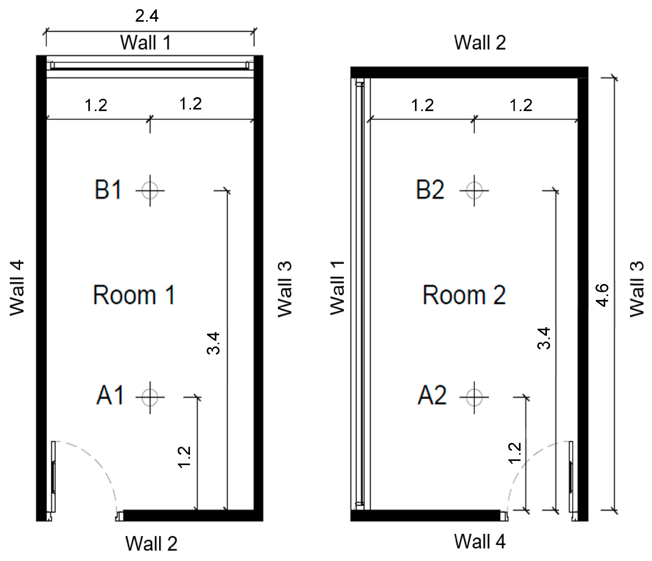
The methodology consists of the calculation of angle factors and heat transfer via a single external wall to analyze and compare the MRT of the room in different case scenarios using the MATLAB-Simulink model. Two case scenarios of an office room with dimensions of 2.4 m × 4.6 m × 2.8 m (Figure 3 and Figure 4) located in Narvik, Norway, with a large window on the exterior wall are simulated. In case I, a 2.4 m × 1.8 m window is located on the shorter wall of the room, whereas in case II, a 4.6 m × 1.8 m window is on the elongated wall of the room. The occupants are located at positions A1 (1.2 m, 1.2 m) and B1 (1.2 m, 3.4 m) in room 1, and A2 (1.2 m, 1.2 m) and B2 (1.2 m, 3.4 m) in room 2 for both seated and standing postures.
The angle factor calculations for seated and standing occupants are based on Equations (3) and (4), Figure 1, and Table 1 [5]. The equations are presented as blocks/subsystems in MATLAB-Simulink for a clear visual representation of the process of the calculation (Figure 4). The surface elements (a, b, and c), the height of the room, and the window dimension are provided at the dimension input. The angle factors are calculated for each section of each surface separately (Figure 3), except for wall 1. Wall 1 is the exterior wall that has windows and is divided into six sections while standing and eight sections while seated. The summation of all the angle factors for the surfaces forming an enclosure must be unity [5,22], and the Simulink simulation results show that the angle factors are acceptable (Table 3). The angle factor between the occupants and the floor is higher compared to other surfaces for seated posture, which agrees with the finding [23].
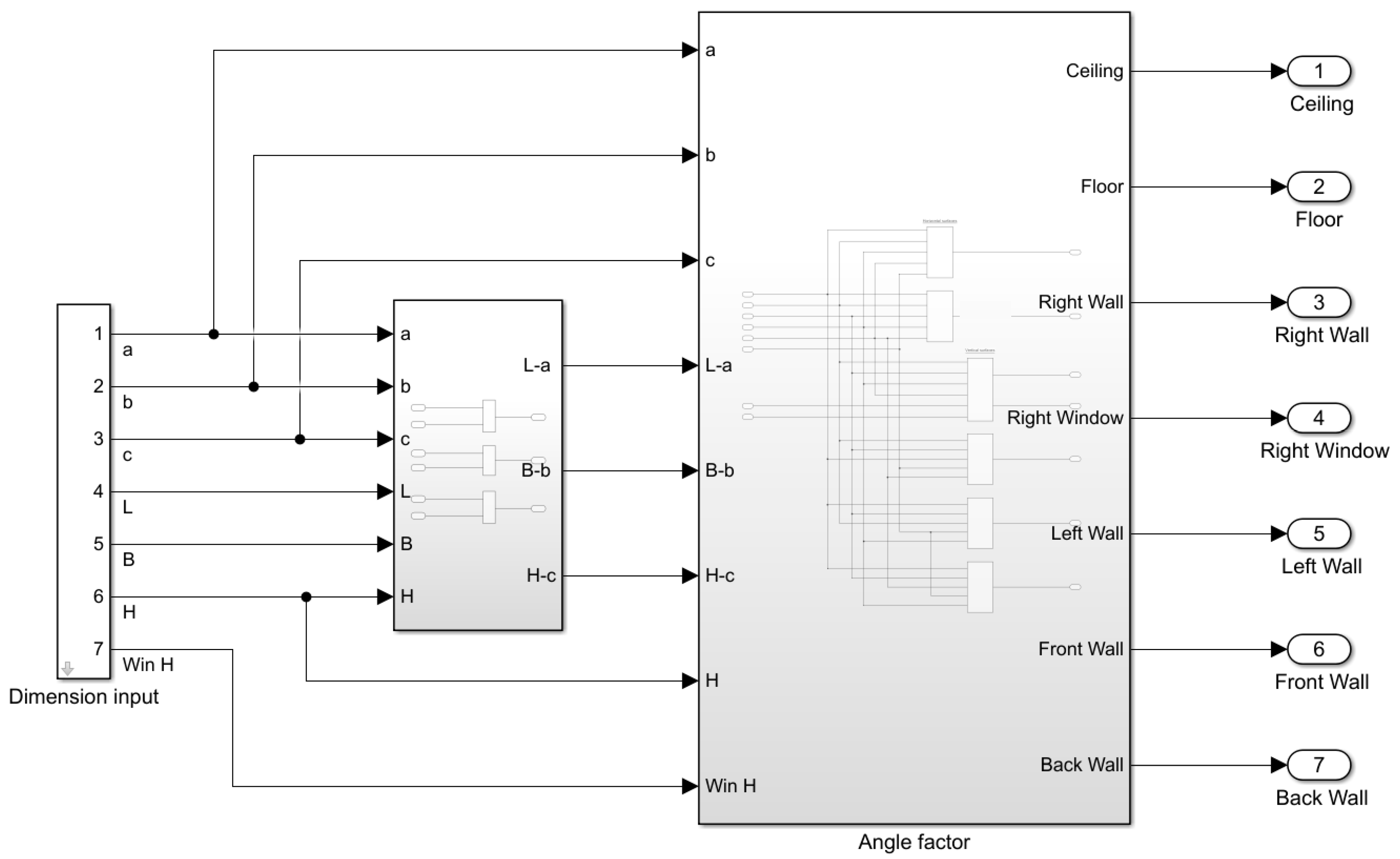
The graphical editor in Simulink enables a structured view of the model with block libraries and solvers to model and simulate dynamic systems. The model in Simulink follows a set of specific mathematical equations for each task that is time-consuming to build, but when the model is complete, the iterative and tedious calculations are simulated by the model (Figure 5). The input requirements are the dimension of the room, window, and occupant posture and position for all case scenarios. The dimension of the room is denoted by length (L), breadth (B) and height (H) along with the surface elements a, b, c and window height (win H). The elements L-a, B-b and H-c are the surface elements of different sections of the wall for each 6 surfaces of the room. The angle factors, U-values of the exterior wall and window, outdoor temperatures, and surface temperatures contribute to the calculation of MRT and thereafter OT. The surface temperature of all internal surfaces is assumed to be constant at 22 °C except for external wall 1, where the surface temperature calculation is based on Equation (10). The room air temperature is assumed to be constant at 24 °C, and hence OT is influenced by only MRT in the model. The boundary conditions listed in Table 4 were considered for the simulation.
The thermal simulation model of one exterior wall with a large window is analyzed for both rooms 1 and 2. Three types of exterior facades with different U-values of wall and window are modelled at five different temperature conditions. The U-values of walls and windows (Table 2) were taken from Norwegian Building Technical Regulations (TEK) from the year 1987 (TEK87), 1997 (TEK97), and 2017 (TEK17). The walls built with TEK87, TEK97, and TEK17 are termed as low U-value, medium U-value, and standard U-value, respectively, in the model. The impact of the exterior wall and window on the room is measured by MRT at a constant outdoor temperature of 0 °C, −10 °C, and −20 °C and altering outdoor temperature during summer (July) and winter (January) temperatures in Northern Norway. A total of 120 different scenarios are simulated with the combination of three types of walls, five types of outdoor temperatures, four occupant positions, and two postures.
3. Results
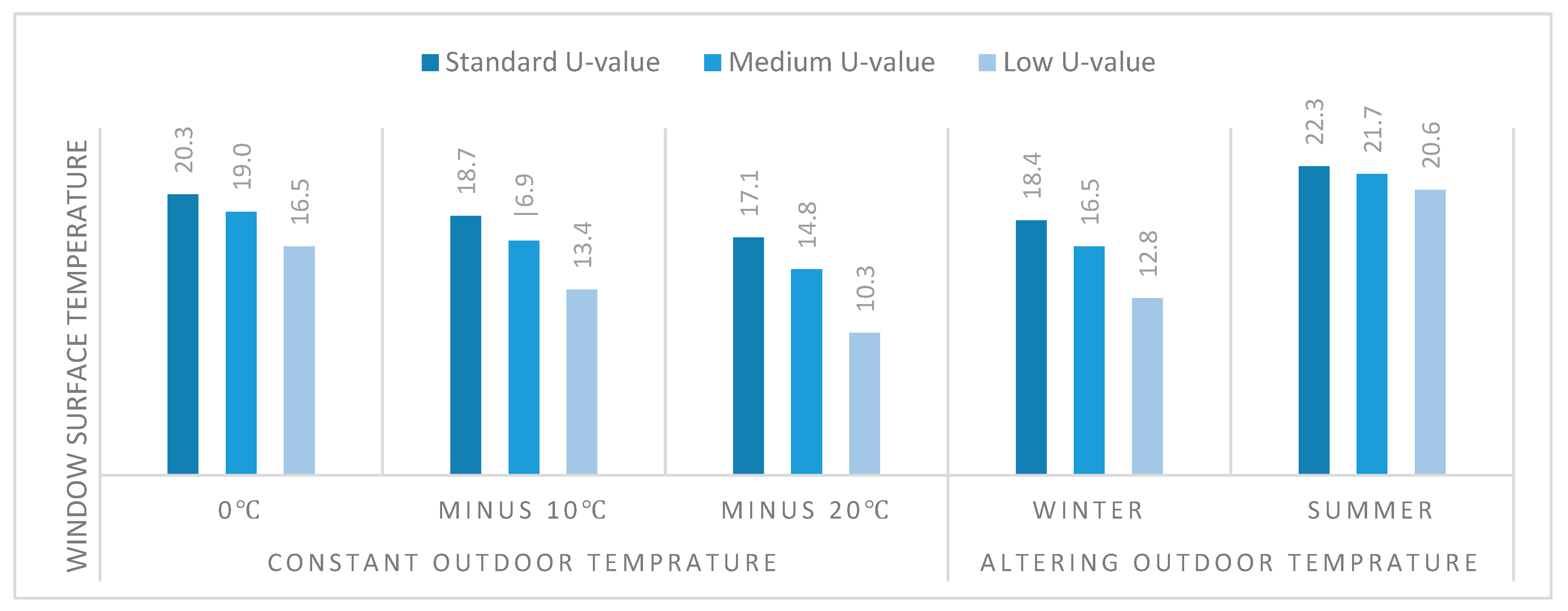
This study examines the effects of parameters by solving one-dimensional heat flow in Simulink using a typical exterior facade construction with three different U-values and controlled outdoor boundary conditions during winter and summer conditions. Figure 6 shows window surface temperature (WST) at 0 °C, −10 °C, and −20 °C, as well as altering outdoor temperature. The temperature fluctuation for the altering outdoor temperature is derived from the weather data [24] of a particular warm day in July and a cold day in January. The WST of the warmer days is higher, and the WST of the colder days is lower, as expected. The standard U-value windows provide better insulation that maintains a comfortable indoor air temperature despite the outdoor temperature. The maximum WST is 22.30 °C during the summer day of the standard U-value window, and the minimum WST is 10.30 °C achieved at the low U-value window during the minimum temperature condition of −20 °C.
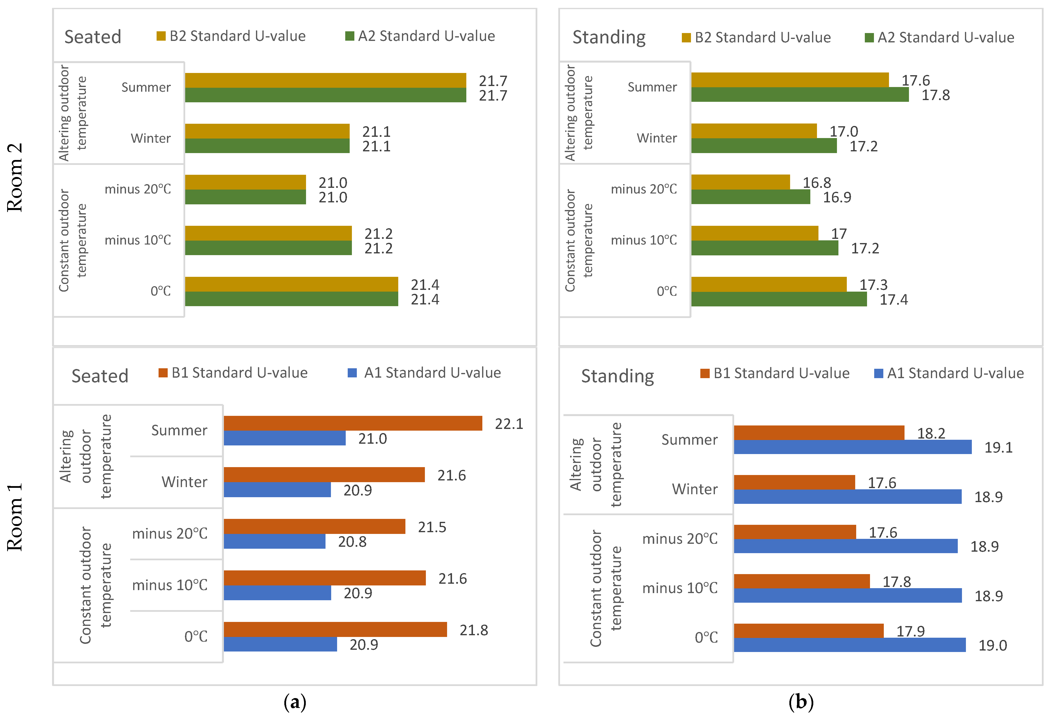
The temperature difference between the standard, medium, and low U-values decreases in descending order. Figure 6 below shows MRT values of the standard U-value envelope simulated at occupant positions A2 and B2 of room 2 and A1 and B1 of room 1 for seated (Figure 7a) and standing (Figure 7b) postures. Since both occupants are equally exposed to the exterior window and interior walls in room 2, the MRTs for both A2 and B2 are the same in the seated posture for all outdoor temperature scenarios. The highest MRT is 21.70 °C during a real summer day with an altering outdoor temperature, and the lowest MRT is 21.0 °C during a −20 °C outdoor temperature. In standing posture, there is a deviation from the expected equal temperature. During summer, the highest MRT of 17.80 °C is observed at the A2 position within room 2. In addition, the B2 position has a temperature around 0.20 °C lower than A2, which may be due to the fact that the sum of angle factors is not exactly 1.
In room 1, the temperature differences range from 0.60 °C to 1.10 °C between A1 and B1 positions for seated posture and 1.0 °C to 1.80 °C for standing posture. For seated posture, the MRT is lowest at 20.80 °C at a constant outdoor temperature of −20 °C when the occupant is positioned at A1. The highest MRT of 22.10 °C is observed during the summer period at B1, which is near the window. In standing posture, the MRT is lowest at 17.60 °C during a real-weather winter day and a constant outdoor temperature of −20 °C at the B1 occupant position. The MRT is at its highest temperature of 19.10 °C during the summer period at the A1 occupant position.
In the seated posture of room 1, the MRT of B1 is higher during all temperature variations than A1 since B1 is nearer to the window. However, in standing posture, the MRT of B1 is lower than that of A1. This contradicts the previous statement about B1 being near the window. One reason could be that standing posture exposes humans to more radiation. Tanabe [6] states that there is a 5% increase in effective radiation area in radiation exchange between a human body and its surroundings at a standing posture. Another possible explanation is that when seated near a wall with a window, the human body is closer to the wall section than the window section. Contrarily, when standing in the same position, the lower temperature from the window glass panel has a greater impact on the human body than the wall part. As a result, at the B1 position, the MRT difference can go up to 4 °C between seated and standing postures during summer conditions.
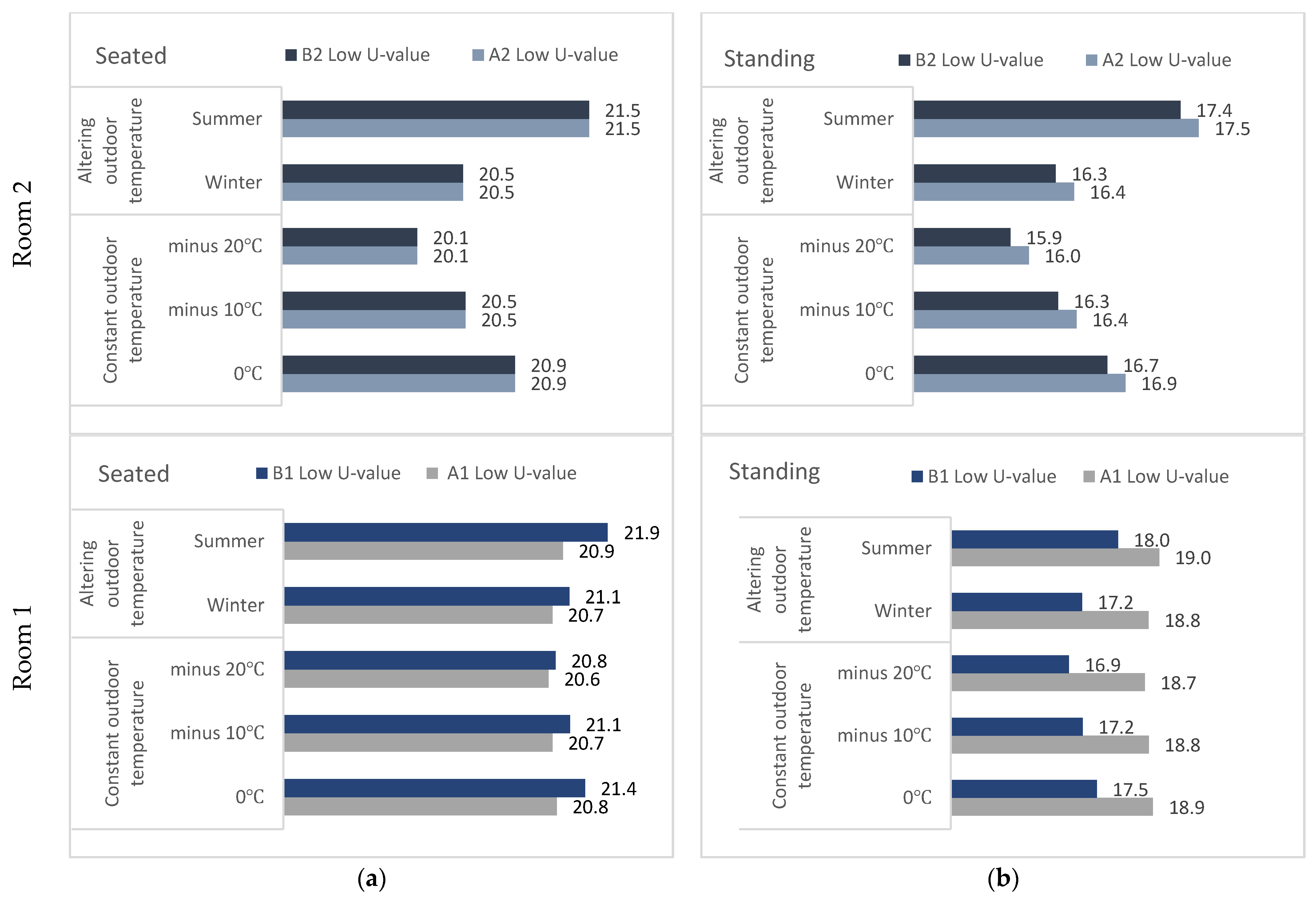
The MRT values of the low U-value envelope simulated at occupant positions A1, B1, A2, and B2 (Figure 8) for both rooms have the same temperature gradient as the MRT of the standard U-value envelope. The only difference is that the temperature is lower in the former. For room 2, both occupants at A2 and B2 have equal temperatures while seated, and while standing, there is a difference of 0.2 °C between A2 and B2. The highest MRT is 21.50 °C during a summer day with an altering outdoor temperature, and the lowest MRT is 20.10 °C during a −20 °C outdoor temperature.
For room 1, the MRT difference between A1 and B1 positions for seated posture is from 0.10 °C to 0.90 °C, and for standing posture, it is from 0.40 °C to 0.60 °C for low U-values. For seated posture, the highest MRT is 21.90 °C during summer at the B1 position, and the lowest MRT is 20.60 °C during a −20 °C outdoor temperature at the A1 position. For standing posture, the temperature difference between A1 and B1 is low, despite A1 being far away from the window. The highest MRT is 19.0 °C during summer at the A1 position, and the lowest MRT is 16.90 °C at a −20 °C outdoor temperature at the B1 position. The temperature difference between seated and standing postures is approximately 1.90 °C for A1 for both standard and low building envelopes. The temperature difference between sitting and standing for B1 is around 3.90 °C for both standard and low building envelopes. The B1 occupant located near the window is exposed to heat or cold from the window, and the temperature difference is therefore higher.
There is a small difference of 1.30 °C in the standard U-value walls between the warmest day in Summer and the hypothetical coldest day of −20 °C in room 1. At a constant outdoor temperature of −20 °C, the MRT is lowest at the A1 position near the internal wall, which is not practically viable. As mentioned, a constant 24 °C air temperature is always provided to the room, making a low difference in MRT. The heater is installed under the window, and all the heat gains from clothing, the activity level of the person, and electrical equipment are considered to supplement the internal indoor air temperature of 24 °C. Kalmár et al. [25] state that when the air temperature is chosen properly, rooms with a cold external wall do not lead to discomfort due to wall heating. The modeling results confirm this statement. For instance, even under the extremely cold outdoor temperature of −20 °C, the seated person near the window (B1) experiences a comfortable 21.50 °C MRT.
4. Conclusions
It is a pre-requirement in Norway that OT should be between 20 and 24 °C within an indoor environment to achieve satisfactory thermal comfort for the human body according to ergonomic standards. This paper presents a methodology simulated in MATLAB-Simulink to investigate the impact of single external wall heat transfer on the seated and standing occupant postures and occupant positions located at positions A and B for rooms 1 and 2. The model maintains the MRT temperature range for the walls and windows with a standard U-value for all weather conditions. This approach shows that the latest TEK17 has the potential to reduce heat loss and save energy.
The angle factors are simulated with respect to the occupant posture, position, and outdoor temperature variation that contribute to the measurement of MRT. The angle factors for each surface element are around unity and are considered acceptable. The results show that standing posture is exposed to more radiation and has a lower MRT than seated posture. When occupants are placed equally distanced from the window and the internal walls in room 2, the MRT is equal for seated and almost equal for standing positions, with a 0.20 °C difference between the occupants. Practically, the occupant near the window should experience cooler temperatures during the cold climate in room 1. For standing posture, this statement is correct. However, for seated posture, the occupant (B1) closer to the window in room 1 has a 0.60 °C to 1.10 °C higher MRT for a standard U-value and a 0.10 °C to 0.90 °C higher MRT for a low U-value. The reason for this may be the hypothetical scenario of constant indoor air temperature at 24 °C provided in the model, which has a significant effect on the wall/window surfaces and room temperature. Even in minus outdoor temperatures, the rooms with standard and low U-values maintain MRT from around 16 °C to 24 °C. In practice, the room temperature would drop, requiring enormous energy consumption.
Author Contributions
Conceptualization, B.R.S.; Methodology, S.T.; Software, S.T.; Validation, S.T.; Writing—original draft, S.T.; Writing—review & editing, L.C.; Supervision, B.R.S. All authors have read and agreed to the published version of the manuscript.
Funding
The publication charges for this article have been jointly funded by the Green Arctic Building (GrAB) and the publication fund of UiT at the Arctic University of Norway (project ID number: KO1089 and UiT organization number: 970422528).
Data Availability Statement
Data available at Dataverse.no.
Conflicts of Interest
The authors declare no conflict of interest.
References
- ASHRAE Standard. Thermal Environmental Conditions for Human Occupancy. ANSI/ASHRAE 2017, 66, 1041–2336. [Google Scholar]
- ISO 7730; Ergonomics of the Thermal Environment-Analytical Determination and Interpretation of Thermal Comfort Using Calculation of the PMV and PPD Indices and Local Thermal Comfort Criteria. ISO: Geneve, Switzerland, 2005.
- Fanger, P.O. Thermal Comfort Analysis and Applications in Environmental Engineering; Mcgraw Hill: New York, NY, USA, 1970; ISBN 9780070199156. [Google Scholar]
- Olsen, E.C.B. Evaluation of Human Work, 3rd ed.; Wilson, J.R., Corlett, N., Eds.; SAGE Publications Inc.: Thousand Oaks, CA, USA, 2007; Volume 15. [Google Scholar]
- ISO 7726; Ergonomics of the Thermal Environment-Instruments for Measuring Physical Qantities. ISO: Geneve, Switzerland, 2001.
- Tanabe, S.I.; Narita, C.; Ozeki, Y.; Konishi, M. Effective radiation area of human body calculated by a numerical simulation. Energy Build. 2000, 32, 205–215. [Google Scholar] [CrossRef]
- Rizzo, G.; Franzitta, G.; Cannistraro, G. Algorithms for the calculation of the mean projected area factors of seated and standing persons. Energy Build. 1991, 17, 221–230. [Google Scholar] [CrossRef]
- Ozeki, Y.; Konishi, M.; Narita, C.; Tanabe, S. Angle factors between human body and rectangular planes calculated by a numerical model. ASHRAE Trans. 2000, 106. [Google Scholar] [CrossRef] [Green Version]
- Sørensen, D.N. Radiation between segments of the seated human body. In Proceedings of the 8th International Conference on Air Distribution in Rooms: Individually Controlled Environment, Copenhagen, Denmark, 8–11 September 2002; Available online: https://orbit.dtu.dk/en/publications/radiation-between-segments-of-the-seated-human-body (accessed on 16 September 2022).
- Yoo, S. Mathematical solutions for mean radiant temperature calculation in a rectangular or non-rectangular geometry temperature calculation in a rectangular or non-rectangular geometry. Int. J. Adv. Mech. Civ. Eng. 2018, 1, 42–46. [Google Scholar]
- Zmrha, V.; Drka, F. Using energy simulation to operative temperature evaluation. In Proceedings of the IBPSA 2007—International Building Performance Simulation Association, Beijing, China, 3–7 September 2007; pp. 878–885. [Google Scholar]
- D’Ambrosio Alfano, F.R.; Dell’Isola, M.; Palella, B.I.; Riccio, G.; Russi, A. On the measurement of the mean radiant temperature and its influence on the indoor thermal environment assessment. Build. Environ. 2013, 63, 79–88. [Google Scholar] [CrossRef]
- Christensen, J.E. A Method for more specific Simulation of Operative Temperature in thermal analysis programmes. In Proceedings of the Building Physics 2008—8th Nordic Symposium, Copenhagen, Denmark, 16 June 2008; pp. 551–558. [Google Scholar]
- Prek, M.; Novak, P. Numerical Calculation of Mean Radiant Temperature for Complex Room Geometry. In Proceedings of the Indoor Air 2002, Monterey, CA, USA, 30 June–5 July 2002; pp. 15–18. [Google Scholar]
- Vorre, M.H.; Jensen, R.L.; Le Dréau, J. Radiation exchange between persons and surfaces for building energy simulations. Energy Build. 2015, 101, 110–121. [Google Scholar] [CrossRef]
- Özbey, M.F.; Turhan, C. The importance of the calculation of angle factors to determine the mean radiant temperature in temperate climate zone: A university office building case. IndIndoor Built Environ. 2021, 31, 1004–1017. [Google Scholar] [CrossRef]
- Tomorad, J.; Horvat, I.; Dović, D. Study of operative temperature using the novel detail approach in determining mean radiant temperature—Comparison between wall-mounted convector and conventional radiator. Trans. Famena 2018, 42, 27–38. [Google Scholar] [CrossRef] [Green Version]
- ISO 6946; Building Components and Building Elements—Thermal Resistance and Thermal Transmittance—Calculation Methods. ISO: Geneve, Switzerland, 2017.
- Cengel, Y.A. Heat Transfer: A Practical Approach; McGraw-Hill: New York, NY, USA, 2004; Volume 4, p. 874. [Google Scholar] [CrossRef]
- Riise, R.; Sørensen, B.R. Energy Requirements in Norwegian Technical Regulations; Economic Science Press and Chinese Railway Publishing House: Beijing, China, 2007; pp. 314–320. [Google Scholar]
- Direktoratet for Byggkvalitet. Building Technical Regulations TEK 17; Direktoratet for Byggkvalitet: Oslo, Norway, 2022. [Google Scholar]
- Beausoleil-Morrison, I. Fundamentals of Building Performance Simulation; Routledge: London, UK, 2020. [Google Scholar]
- Wang, Y.; Meng, X.; Zhang, L.; Liu, Y.; Long, E. Angle Factor Calculation for the Thermal Radiation Environment of the Human Body; Springer: Berlin/Heidelberg, Germany, 2014. [Google Scholar] [CrossRef]
- Crawley, D.B.; Lawrie, L.K. Development of Global Typical Meteorological Years (TMYx). Available online: https://climate.onebuilding.org/WMO_Region_6_Europe/NOR_Norway/index.html (accessed on 16 September 2022).
- Kalmár, F.; Kalmár, T. Numerical evaluation of thermal discomfort in conditions of surface heating and asymmetric radiation. Int. Rev. Appl. Sci. Eng. 2019, 9, 175–179. [Google Scholar] [CrossRef]
Figure 1.
Visualization for angle factor calculation between a seated/standing person and a section of vertical surface [5].
Figure 1.
Visualization for angle factor calculation between a seated/standing person and a section of vertical surface [5].

Figure 2.
Simple wall temperature gradient.

Figure 3.
The room model dimensions and occupant position.

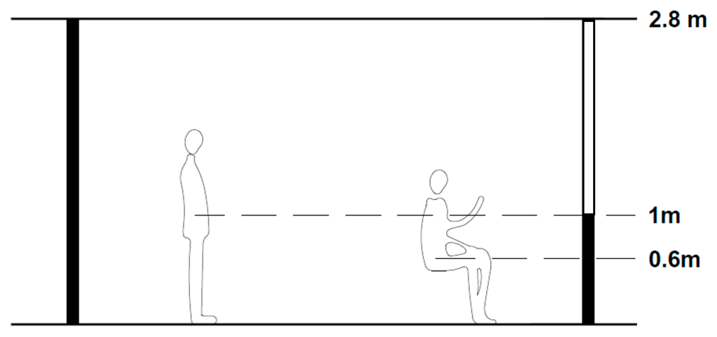
Figure 4.
Section of room 2 with occupants seated and standing.

Figure 5.
MATLAB-Simulink room model for angle factor calculation.

Figure 6.
Window surface temperatures at different outdoor temperatures in both room models 1 and 2.
Figure 6.
Window surface temperatures at different outdoor temperatures in both room models 1 and 2.

Figure 7.
MRT in room 2 (positions A2 and B2) and in room 1 (positions A1 and B1) at (a) seated and (b) standing postures with a standard U-value (TEK17) of the external wall at different outdoor temperatures.
Figure 7.
MRT in room 2 (positions A2 and B2) and in room 1 (positions A1 and B1) at (a) seated and (b) standing postures with a standard U-value (TEK17) of the external wall at different outdoor temperatures.

Figure 8.
MRT in room 2 (positions A2 and B2) and in room 1 (positions A1 and B1) at (a) seated and (b) standing postures with low U-value (TEK87) of the external wall at different outdoor temperatures.
Figure 8.
MRT in room 2 (positions A2 and B2) and in room 1 (positions A1 and B1) at (a) seated and (b) standing postures with low U-value (TEK87) of the external wall at different outdoor temperatures.


Table 1.
Constant factors for calculation of angle factors for seated and standing postures and vertical and horizontal surfaces [5].
Table 1.
Constant factors for calculation of angle factors for seated and standing postures and vertical and horizontal surfaces [5].
| Fmax | A | B | C | D | E | |
|---|---|---|---|---|---|---|
| Seated Person, Vertical Surfaces 1 | 0.118 | 1.216 | 0.169 | 0.717 | 0.087 | 0.052 |
| Seated Person, Horizontal Surfaces 2 | 0.116 | 1.396 | 0.130 | 0.951 | 0.080 | 0.055 |
| Standing Person, Vertical Surfaces 1 | 0.120 | 1.242 | 0.167 | 0.616 | 0.082 | 0.051 |
| Standing Person, Horizontal Surfaces 2 | 0.116 | 1.595 | 0.128 | 1.226 | 0.046 | 0.044 |
1 Wall and window. 2 Floor and ceiling.
Table 2.
Maximum allowed thermal transmittance in the Building Technical Regulations (TEK) in 1987, 1997, 2007, 2010, and 2017 [20,21].
| Maximum Thermal Transmittance (U-Value) [W/m2K] | |||||
|---|---|---|---|---|---|
| TEK | 1987 | 1997 | 2007 | 2010 | 2017 |
| External Wall | 0.3 | 0.22 | 0.18 | 0.18 | 0.18 |
| Window | 2.4 | 1.6 | 1.2 | 1.2 | 1.2 |
Table 3.
Angle factor of the room model for seated and standing occupants at positions A and B of the room.
Table 3.
Angle factor of the room model for seated and standing occupants at positions A and B of the room.
| Room Surface | Angle Factor (FP-N) | |||||||
|---|---|---|---|---|---|---|---|---|
| Position A Room 1 | Position B Room 1 | Position A Room 2 | Position B Room 2 | |||||
| Seated | Standing | Seated | Standing | Seated | Standing | Seated | Standing | |
| Wall 1 | 0.020 | 0.02 | 0.10 | 0.08 | 0.12 | 0.10 | 0.12 | 0.10 |
| Window 1 | 0.028 | 0.03 | 0.10 | 0.10 | 0.12 | 0.13 | 0.12 | 0.13 |
| Wall 2 | 0.160 | 0.19 | 0.04 | 0.05 | 0.20 | 0.23 | 0.20 | 0.23 |
| Wall 3 | 0.200 | 0.23 | 0.20 | 0.24 | 0.16 | 0.19 | 0.16 | 0.05 |
| Wall 4 | 0.200 | 0.23 | 0.20 | 0.23 | 0.04 | 0.05 | 0.04 | 0.18 |
| Floor | 0.290 | 0.18 | 0.29 | 0.18 | 0.29 | 0.17 | 0.29 | 0.17 |
| Ceiling | 0.090 | 0.09 | 0.09 | 0.09 | 0.08 | 0.09 | 0.08 | 0.09 |
| Total (FP-N) | 0.99 | 0.97 | 1.02 | 0.97 | 1.02 | 0.97 | 1.02 | 0.96 |
Table 4.
Boundary conditions for simulations.
| Standard | Medium | Low | |||
|---|---|---|---|---|---|
| U-value Wall [m2/K] | 0.18 | 0.22 | 0.3 | ||
| U-value Window [m2/K] | 1.2 | 1.6 | 2.4 | ||
| Constant | Altering | ||||
| Summer | Winter | ||||
| Outdoor temperature [°C] | 0 | −10 | −20 | 15 | −10 |
| Heat transfer coefficient (hi) | 1/0.13 | ||||
| Indoor wall surface temperature [°C] | 22 | ||||
| Air temperature [°C] | 24 | ||||
Disclaimer/Publisher’s Note: The statements, opinions and data contained in all publications are solely those of the individual author(s) and contributor(s) and not of MDPI and/or the editor(s). MDPI and/or the editor(s) disclaim responsibility for any injury to people or property resulting from any ideas, methods, instructions or products referred to in the content. |
© 2023 by the authors. Licensee MDPI, Basel, Switzerland. This article is an open access article distributed under the terms and conditions of the Creative Commons Attribution (CC BY) license (https://creativecommons.org/licenses/by/4.0/).
Share and Cite
MDPI and ACS Style
Tamrakar, S.; Chen, L.; Sørensen, B.R. Variation of Mean Radiant Temperature in Rooms for Summer and Winter Conditions. Energies 2023, 16, 5609. https://0-doi-org.brum.beds.ac.uk/10.3390/en16155609
AMA Style
Tamrakar S, Chen L, Sørensen BR. Variation of Mean Radiant Temperature in Rooms for Summer and Winter Conditions. Energies. 2023; 16(15):5609. https://0-doi-org.brum.beds.ac.uk/10.3390/en16155609
Chicago/Turabian StyleTamrakar, Stutee, Liguo Chen, and Bjørn Reidar Sørensen. 2023. "Variation of Mean Radiant Temperature in Rooms for Summer and Winter Conditions" Energies 16, no. 15: 5609. https://0-doi-org.brum.beds.ac.uk/10.3390/en16155609
Note that from the first issue of 2016, this journal uses article numbers instead of page numbers. See further details here.