
Heat Transfer Mechanisms and Contributions of Wearable Thermoelectrics to Personal Thermal Management


1
Electronics, Telecommunications and Energy Department, University Valahia of Targoviste, 130004 Targoviste, Romania
2
Istituto Nazionale di Ricerca Metrologica (INRiM), 10135 Torino, Italy
Energies 2024, 17(2), 285; https://0-doi-org.brum.beds.ac.uk/10.3390/en17020285
Submission received: 27 November 2023
/
Revised: 26 December 2023
/
Accepted: 29 December 2023
/
Published: 5 January 2024
(This article belongs to the Special Issue Advanced Studies of Thermoelectric Systems)
Abstract
:Thermoelectricity can assist in creating comfortable thermal environments through wearable solutions and local applications that keep the temperature comfortable around individuals. In the analysis of an indoor environment, thermal comfort depends on the global characteristics of the indoor volume and on the local thermal environment where the individuals develop their activity. This paper addresses the heat transfer mechanisms that refer to individuals, which operate in their working ambient when wearable thermoelectric solutions are used for enhancing heating or cooling within the local environment. After recalling the characteristics of the thermoelectric generators and illustrating the heat transfer mechanisms between the human body and the environment, the interactions between wearable thermoelectric generators and the human skin are discussed, considering the analytical representations of the thermal phenomena. The wearable solutions with thermoelectric generators for personal thermal management are then categorized by considering active and passive thermal management methods, natural and assisted heat exchange, autonomous and nonautonomous devices, and direct or indirect contact with the human body.
1. Introduction
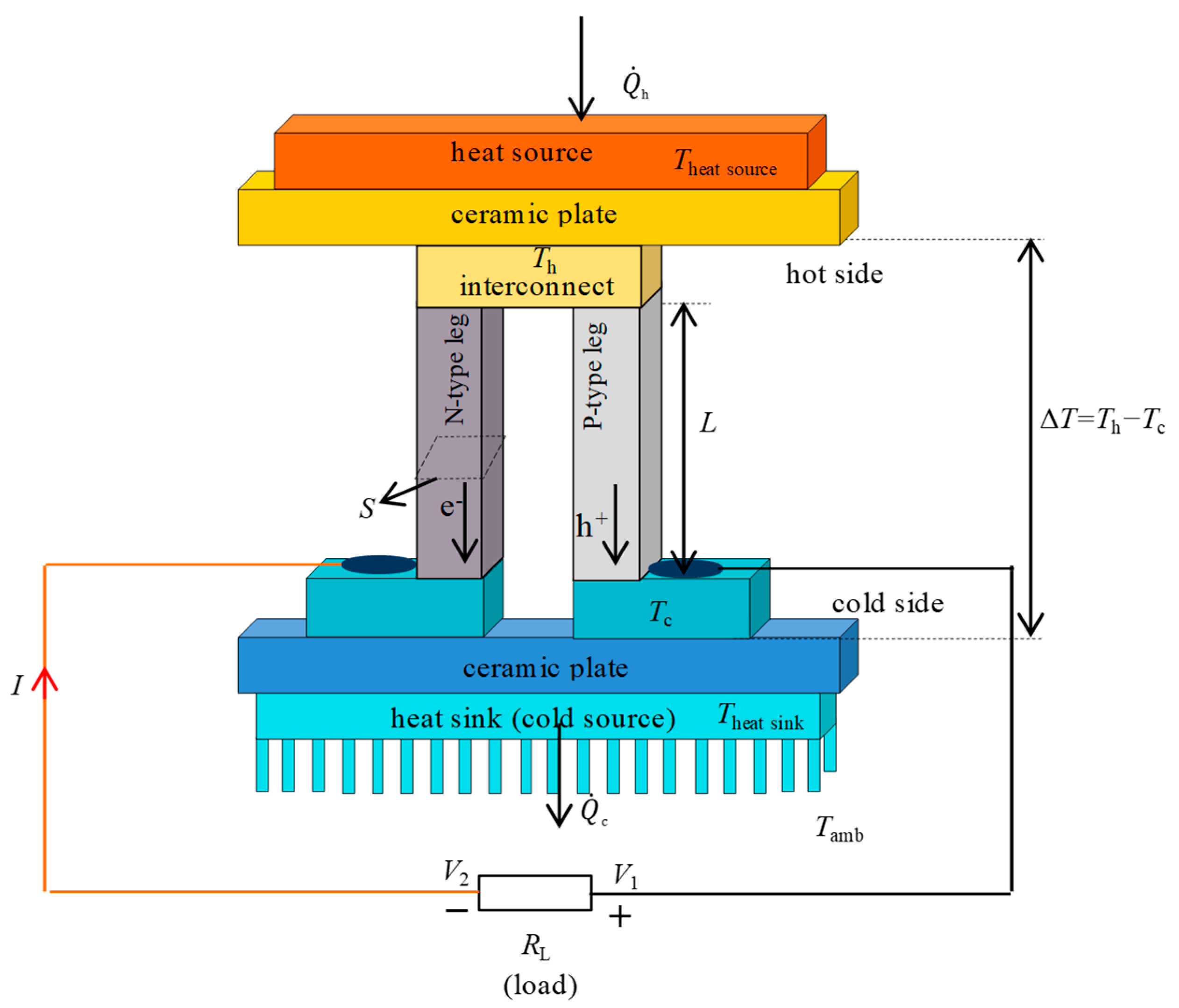
A thermoelectric generator (TEG) is a solid-state device that operates due to the Seebeck phenomenon to harvest electrical energy by converting the temperature difference ΔT determined by human body heat (considered as a heat source) and surrounding conditions into voltage [1]. The parameter called the Seebeck coefficient or thermopower is . The TEG device generates electricity in direct current (DC) as long as there is a temperature difference between its sides. In this way, the TEG operates due to the movement of the charge carriers (electrons and holes) within one or more thermoelement pairs (or thermocouples) connected together. The two thermoelements that form the pair are made of semiconductor materials (N-type and P-type) connected to each other at one end through a metallic strip (or copper interconnect or metal electrodes), forming a junction (as shown in Figure 1). When the junction is subject to a temperature gradient, the heat carriers (electrons and holes) begin to move through the two thermoelements. In the N-type thermoelement of a TEG, there is an excess of negative charge carriers, i.e., electrons. These electrons are set in motion by the temperature gradient and migrate from the hotter side to the colder side, creating an electrical potential. In the P-type thermoelement, there is an excess of positive charge carriers, i.e., holes, which also move in response to the temperature gradient, generating an electrical potential. Both electrons and holes move in the same direction under the same temperature gradient, and this results in the creation of a difference of potential at the TEG terminals.
The thermoelements are arranged in a regular matrix inside the TEG and are connected electrically in series and thermally in parallel. In addition, the thermocouple is placed between two ceramic plates or ceramic substrates. The ceramic plates are excellent electrical insulators and maintain the thermoelements insulated from the electrical point of view. At the same time, the ceramic plates are good conductors from a thermal point of view. In addition, the ceramic plates serve as mechanical support upon which the thermoelements are mounted. The common ceramic plate is made of aluminum oxide (Al2O3). A temperature gradient between the ceramic plates leads to a temperature difference along the thermoelements. Keeping an appropriate temperature gradient along the thermoelements, a heat sink is usually attached to the cold side of the TEGs to speed up the heat dissipation. The higher output voltage and electric power are obtained by rising ΔT between the heat source and the heat sink.
An electrical load having resistance RL can be connected to the output terminals of TEG, creating an electric circuit in which there is the circulation of a current.
Figure 1.
Sketch of the traditional TEG device (the incoming heat flow at the hot side of TEG; the outcoming heat flow at the cold side of TEG) [2].
Figure 1.
Sketch of the traditional TEG device (the incoming heat flow at the hot side of TEG; the outcoming heat flow at the cold side of TEG) [2].

The efficiency of the thermoelectric material is gauged by the dimensionless figure of merit , which depends on the three transport properties of the material (electrical conductivity , thermal conductivity , and Seebeck coefficient ), as well as the mean absolute temperature , and is given by the following equation:
The mean absolute temperature is the arithmetic mean between the temperature at the hot side and the temperature at the cold side.
The product is the power factor, representing the main parameter to evaluate the performance of the thermoelectric materials. A thermoelectric material requires high-power factor (high and high ), and low The thermal conductivity of a semiconductor depends on the charge carriers’ thermal conductivity and the lattice’s thermal conductivity:
The charge carrier thermal conductivity depends on the Lorenz constant , the electrical conductivity and the absolute temperature according to the Wiedemann–Franz law:
The thermal conductivity of the lattice is given by:
where is the thermal diffusivity, is the specific heat at constant pressure and is the density.
There is no theoretical limit for the dimensionless figure of merit, but the most efficient semiconductor materials used today have values around unity at room temperature.
The conversion efficiency of the TEGs depends on the dimensionless figure of merit and the temperature difference along the thermoelements, .
The maximum theoretical conversion efficiency of a TEG is given by:
where is the Carnot efficiency, which represents a superior limit on using waste heat for thermoelectric power generation [3]. The maximum theoretical conversion efficiency of the TEG is directly influenced by . Raising along the thermoelements, the maximum conversion efficiency of the TEG rises. To regulate , one of the most encouraging approaches is the analysis of the structural design of the thermoelements with respect to the optimal ratio of the cross-sectional area of the P-type (SP) and N-type (SN) thermoelements [4]. The optimal ratio is given by:
Structural design classifies TEGs into two categories: flexible TEGs and rigid TEGs. The rigid TEGs have a sandwich structure, while flexible TEGs feature a thin-film structure or fabric-based construction. Furthermore, rigid TEGs are used in powering medical equipment, while flexible TEGs are used for powering wearable equipment [4,5]. In the case of rigid TEGs, the thermoelements are linked using copper strips and are placed between ceramic plates such as alumina (with a thermal conductivity of approximately 30 W/(m∙K) or aluminum nitride (with thermal conductivity of approximately 285 W/(m∙K)) [6]. For the flexible TEGs, the rigid substrates are eliminated, and the gap between thermoelements is filled with filler material (e.g., flexible polymers with very low thermal conductivity, while the exposed copper strips are into contact with the body’s skin [4]). In flexible TEGs, a liquid metal interconnect made of a gallium and indium eutectic alloy (EGaIn) has been used, providing both flexibility and self-healing properties that maintain the TEG module’s integrity even after enduring significant strains [7]. The two most used flexible substrates are polydimethylsiloxane (PDMS) and Kapton HN. However, compared to rigid substrates, flexible substrates can hinder the transfer of heat from the human body to the TEG due to their higher thermal resistance [8]. The flexible TEG has both a cross-plane structural design and an in-plane structural design, while rigid TEG has a cross-plane structural design [1,9]:
- ○
- In the cross-plane structural design, the thermoelements are placed perpendicularly to the substrate. For a curved surface, the cross-plane structural design has a high flexibility degree, which can bend up to 2 mm in radius for a curved surface. For this reason, the cross-plane structural design is more adequate for human body energy applications than the in-plan structural design.
- ○
- In the in-plane structural design, the thermoelements are parallel to the substrate. Due to the low ΔT between the hot and cold sides in the cross-plane structural design, this design cannot generate more power.
The TEG device has several benefits considering it is portable, noiseless, and requires no maintenance [10]. These advantages are also useful for a wearable TEG (w-TEG), which converts the heat generated by the human body into electricity. The w-TEG is used as a battery booster or as a single power source in many wearable electronic devices (e.g., multisensory electronic skin [11], glucose sensors [12], and electrocardiogram sensors [13,14]).
The design and fabrication of TEG devices are limited by the type of material. The utilization of inorganic materials (e.g., bismuth telluride (Bi2Te3) [15,16] and antimony telluride (Sb2Te3) [17,18], lead telluride (PbTe), and germanium telluride (GeTe). Even if these materials have high performance with superior stability at ambient temperature, they are mechanically rigid and require advanced techniques to manufacture the wanted thermoelement structure [19]. For this reason, it is difficult enough to integrate inorganic semiconductors into flexible w-TEGs for harvesting energy from irregular surfaces (e.g., the human wrist) [13]. Inorganic semiconductors are toxic, scarce, and expensive, with relatively poor processability, limiting their large applications. In addition, inorganic semiconductors have high thermal conductivity from about 1.2 to 1.6 W/(m∙K) [20]. Conversely, organic materials, recently exploited in power generation applications, are considered good candidates due to their light weight, flexibility, processibility, low-cost manufacturing, and abundant raw material. In addition, organic materials have a thermal conductivity of around 0.5 W/(m∙K), being very close to the lower limit of inorganic materials [21,22].
This paper contains a review of the application of w-TEG devices for personal thermal management. Unlike other review papers, which have focused on thermoelectric technologies and applications with details on specific materials and devices, this paper takes a different approach. Starting with the heat transfer principles that underlie the interaction between thermoelectric devices and the human body, this paper discusses the implications of using w-TEG for local thermal comfort. Specific applications of wearable thermoelectric devices for monitoring the biophysical parameters [23] or to optimize the design of thermoelectric devices [24] are outside the scope of this paper.
The next sections of this paper are organized as follows: Section 2 discusses the heat transfer mechanisms between the human body and the environment, which are important for understanding how to use the human body as a heat source for w-TEGs. Section 3 addresses the interactions between w-TEG and the human skin, recalling the thermal analytical representations. Section 4 summarizes the use of w-TEGs for personal thermal management. The last section contains the conclusions.
2. Basic Principles of Human Body Dry Heat Transfer to the Environment: Harnessing the Human Body as a Heat Source for Wearable TEGs
2.1. Heat Transfer Mechanisms
Heat transfer from the human body to the surroundings is vital for the human body’s thermoregulation. The human thermoregulatory system utilizes a range of coordinated physiological mechanisms. These mechanisms are:
- ▪
- Insulation, which slows down the transfer of heat from the body, helping maintain a comfortable internal temperature.
- ▪
- Sweating, which cools the body through the evaporation of water.
- ▪
- Shivering, which generates heat via muscle contraction.
- ▪
- Vasodilation and vasoconstriction, which regulate blood flow and distribute heat throughout the body.
When the body’s core temperature rises, mechanisms such as sweating and vasodilation are activated to cool the body. Conversely, when the core temperature falls, the system initiates mechanisms like shivering and vasoconstriction that warm the body [25]. The physiological mechanisms serve as the functional tools the body deploys to execute its thermoregulatory responses.
The human body continuously produces heat through metabolic processes—the chemical reactions within our cells. This metabolic heat is essential to sustain the body’s core temperature, which, for optimal function, should remain around 37 °C (homeothermy). Metabolic heat, also known as metabolic rate, is measured in metabolic equivalents (Met). For example, a sleeping person’s metabolism is roughly 46 W/m2 (0.8 Met), a person sitting in an office has around 70 W/m2 (1.2 Met), and during intense physical activity, the metabolic rate can spike up to 550 W/m2 (9.5 Met) [26]. Metabolic heat production in the human body directly influences the subsequent heat transfer processes, as it determines the amount of heat that needs to be dissipated to maintain the core temperature. The body utilizes several processes for heat transfer, including conduction, convection, radiation, and evaporation. Understanding these mechanisms is crucial, especially in fields like garment design and safety gear. These insights also influence the design of environmental control systems, such as heating, ventilation and air conditioning systems, and lighting, ensuring optimal comfort for the occupants [21].
2.2. Conductive Heat Transfer
Conductive heat transfer takes place when a part of the body comes into contact with a solid surface in the environment. Conductive heat exchange depends on the surface area of body parts in direct contact with external surfaces, and it is typically minimal.
In steady-state conditions, the conductive thermal flux density is expressed by the following equation:
where k is the thermal conductivity in W/(mK), which is influenced by the thermal properties of both the skin and the solid surface and by the contact solid surface area, is the temperature of the skin body in °C, and is the temperature of the solid surface in °C. In transient conditions, the heat that is exchanged between the skin and the solid surface depends on the thermal inertia of the material. The Merriam-Webster online dictionary defines “thermal inertia” as “the degree of slowness with which the temperature of a body approaches that of its surroundings and which is dependent upon its absorptivity, its specific heat, its thermal conductivity, its dimensions, and other factors” [27]. In other words, thermal inertia expresses how quickly a material can absorb or release heat. With higher thermal inertia, more heat is transferred to the skin or removed from the skin. If there is only a small surface area of the body in contact with another material (e.g., a person who is standing), and that material has low thermal inertia, then a small amount of conductive heat will be transferred. On the other hand, if a higher surface area of the body is in contact with a material (e.g., a person lying down on a surface) and that material has high thermal inertia, then a significant amount of conductive heat will be transferred [21,28].
2.3. Convective Heat Transfer
Convective heat transfer refers to the process of carrying heat away from the skin to the surrounding air. The convective thermal flux density from the skin to the surrounding air is expressed by the following equation:
where is the temperature of the surrounding air, and is the convective heat transfer coefficient, which, according to (8), is the ratio of the convective thermal flux density to the temperature difference from the skin to the surrounding air [29]. The greater the temperature difference between the skin and the surrounding air, the faster the rate of convective heat loss. This is because a larger temperature difference results in a stronger convective current, accelerating the heat transfer process.
For the dressed human body, the convective thermal flux density from the clothes to the surrounding air is expressed by the following equation:
where represents the clothing area factor, which represents the ratio between the clothed body surface area compared to the unclothed body surface area. The clothing area factor is estimated as , where is the intrinsic clothing ensemble insulation, in clo ( for the unclothed body surface area), and is the mean surface temperature of the clothed body.
Convective heat transfer from the skin or clothing occurs when moving air perturbs the insulating boundary layer of air around the body’s surface. The more rapid the airflow around the body, the narrow the boundary layer on the body’s surface, leading to lower thermal insulation for the individual [30].
Convection from the human skin or clothing can be divided into the following types:
- -
- Natural convection occurring for the air velocity ;
- -
- Forced convection occurring for the air velocity ;
- -
- Mixed-mode convection, which takes place at air velocity .
Now, having outlined the three main types of convection, it is important to examine the phenomenon of natural convection and the dimensionless parameter known as the Grashof number. The average skin temperature of a naked individual is higher than the surrounding air temperature. Consequently, the layer of air directly touching the skin surface warms up and, as a result, becomes lighter. In calm conditions, this warm air ascends due to buoyancy forces, and colder air from the surrounding environment flows in to take its place [31]. The upward airflow can exhibit either laminar or turbulent characteristics. In the context of natural convection, a crucial dimensionless parameter that describes this flow is the Grashof number (Gr) [29,31]. This parameter quantifies the relationship between buoyant forces and viscous forces and is defined as follows:
where g = 9.81 m/s2 is the gravitational acceleration; is the thermal expansion coefficient of the air; is a characteristic length, identified with body height; and is the kinematic viscosity of the air.
The flow is laminar if [30] and is turbulent for [32]. In the case of a stationary, unclothed individual, with a temperature difference °C, the flow is laminar up to a height of 1 m and turbulent at 1.5 m [32]. Therefore, different flow regimes occur under natural convection and at various height levels, permitting different heat loss rates across body segments.
2.3.1. Natural Convection
Under natural convection (), the convective heat transfer coefficient for the whole human body varies from 3.1 to 5.1 W/(m2∙K), according to different studies [30,33].
Xu et al. [34] analyzed the possible reasons for this variation, including differences in body geometry, body posture, and airflow patterns in the investigated room.
Under natural convection, for a clothed body, the general equation used by many researchers is structured as:
where and are the coefficients determined by the specific analyses carried out by the researchers, while for the naked human body the equation is structured as:
Table 1 shows the values of the coefficients used in the above equations for clothed or naked human body in various postures.

Table 1.
Coefficients for the representations of the convective heat transfer coefficients under natural convection.
Table 1.
Coefficients for the representations of the convective heat transfer coefficients under natural convection.
| Posture | (m/s) | Human Body | Reference | ||
|---|---|---|---|---|---|
| Sitting | 2.38 | 0.25 | <0.15 | clothed | [35] |
| Sitting | 0.78 | 0.59 | <0.1 | naked | [30] |
| Sitting | 1.94 | 0.23 | <0.15 | naked | [36] |
| Sitting (exposed to atmosphere) | 1.175 | 0.351 | <0.2 | naked | [37] |
| Sitting (contact with seat) | 1.222 | 0.299 | <0.2 | naked | [37] |
| Sitting (cross-legged, floor contact) | 1.271 | 0.355 | <0.2 | naked | [37] |
| Sitting (legs out, floor contact) | 1.002 | 0.409 | <0.2 | naked | [37] |
| Standing | 2.35 | 1.25 | naked | [38] | |
| Standing | 1.21 | 0.43 | <0.1 | naked | [39] |
| Standing | 2.02 | 0.24 | <0.15 | naked | [36] |
| Standing | 2.38 | 0.25 | <0.15 | clothed | [35] |
| Standing (exposed to atmosphere) | 1.007 | 0.406 | <0.2 | naked | [37] |
| Sitting (floor contact) | 1.183 | 0.347 | <0.2 | naked | [37] |
| Supine (floor contact) | 0.881 | 0.368 | <0.2 | naked | [37] |
| Lying | 2.48 | 0.18 | <0.15 | naked | [40] |
In other references, only the convective heat transfer coefficients of the human body are indicated. For example, de Dear et al. [30] indicated values in the range from 4 to 6 .
2.3.2. Forced Convection
Under forced convection, numerous efforts have been undertaken throughout the years to empirically determine the convective heat transfer coefficients suitable for the entire human body. The Archimedes number (Ar) plays a key role in determining the relative significance of free and forced convection. Considering the Reynolds number (Re), defined as:
where is a characteristic length associated with the body and is the thermal diffusivity, Ar is the ratio between the Grashof number to the Reynolds number squared:
Sparrow et al. [41] provided a criterion for categorizing various types of convective flow based on the Archimedes number. In this case, for forced convection , for mixed convection , while for natural convection .
In forced convection, where air is blown over the surface, the convective heat transfer coefficient increases with air velocity being a function of it.
For vertical airflow, in the case of the mixed convection, when the air velocity is the following expression holds:
where , , and are the constants determined by the researchers [42]. For example, Colin and Houdas [43] obtained the values = 8.7, = 0.67, and = 2.7 from the regression for sitting, for the air velocity, in m/s, in the range .
The convective heat transfer coefficient for downward airflow conditions was greater than that for upward airflow conditions when the air velocity was below 0.3 m/s. However, as the air velocity surpassed 0.3 m/s, the convective heat transfer coefficient for upward airflow conditions significantly surpassed that for downward airflow conditions [42].
For horizontal airflow, when the air velocity is , the general equation for the forced convection that outlines the relationship of the whole body on the air velocity is given as:
where and are the coefficients determined by the specific analyses carried out by the researchers.
The studies on the convective heat transfer have been carried out on the human body, or on manikins that emulate the human body.
For the studies on the human body, as discussed in [44], the relationships between the air velocity and the convective heat transfer coefficient hc obtained from experimental studies of frontal wind on the human body show large discrepancies among the values of and , which increase with the air velocity [34].
Table 2 reports the coefficients used in the representations found by different authors.
Table 2.
Coefficients for the representations of the convective heat transfer coefficients of the human body under forced convection.
Table 2.
Coefficients for the representations of the convective heat transfer coefficients of the human body under forced convection.
| (m/s) | Reference | ||
|---|---|---|---|
| Downward air currents | 12.1 | 0.5 | [45] |
| (Not indicated) | 8.6 | 0.531 | [46] |
| 6.51 | 0.391 | [47] | |
| 14.8 | 0.69 | [48] | |
| (Not indicated) | 8.3 | 0.5 | [49] |
| 8.7 | 0.6 | [50] | |
| (Not indicated) | 8.3 | 0.6 | [51] |
| Still air | 8.6 | 0.5 | [46] |
Both theoretical and experimental methods have been applied to heated thermal manikins with varied body shapes, sizes, and postures. A thermal manikin is a device used for evaluating human thermal environments because it accurately replicates human heat production, heat dissipation, and body shape [52]. The measurements of the heat transfer coefficients for every part of the body are impacted by the ambient factors, specifically, the temperature difference between the human body and its surroundings, the wind velocity, and the body’s position and walking speed [53].
A literature review reveals that, in the context of thermal manikin experiments involving forced convection, researchers typically disregarded the influence of free convection, due to the condition Ar << 1 [54]. However, when a variable temperature gradient is present, there can be situations where the effects of natural and forced convection are comparable. In such cases, it is inappropriate to neglect either of these processes. In combined natural and forced convection scenarios, both natural and forced convection mechanisms play a role in heat transfer [54].
Over time, many studies have tried to create a useful database for predicting the convective heat transfer coefficient for the human body. A general form of the empirical formulas where the convective heat transfer coefficient is influenced by the air velocity, as seen in Equation (16). Table 3 shows the coefficients determined by different studies with the use of manikins.
Table 3.
Coefficients for the representations of the convective heat transfer coefficients under forced convection by using manikins.
Table 3.
Coefficients for the representations of the convective heat transfer coefficients under forced convection by using manikins.
| (m/s) | Position | Note | Reference | ||
|---|---|---|---|---|---|
| Sitting | [55] | ||||
| Standing | 15.4 | 0.63 | [56] | ||
| , upstream flow | Sitting or standing | Nude | 9.31 | 0.60 | [57] |
| , downstream flow | Sitting or standing | Nude | 9.41 | 0.61 | [57] |
| , upstream flow | Sitting or standing | Clothed | 13.36 | 0.60 | [57] |
| , downstream flow | Sitting or standing | Clothed | 12.38 | 0.65 | [57] |
| Sitting | 10.1 | 0.61 | [30] | ||
| Standing | 10.4 | 0.56 | [30] | ||
| Sitting or standing | 10.3 | 0.6 | [30] | ||
| Walking | 8.17 | 0.43 | [58] | ||
| Standing | 7.34 | 0.49 | [58] |
There are some discrepancies in the values shown in Table 3, which can be partially explained by body geometry and body posture, as the difference for standing and sitting postures using the same manikin. Moreover, some discrepancies could be explained by the fact that many studies neglect the turbulence intensity.
When turbulence intensity is taken into account, the formulation of the convective heat transfer coefficient becomes more articulate than the structure of Equation (16). Ono et al. [59] determined the convective heat transfer coefficient for the human body in an outdoor environment using a combination of wind tunnel testing and computational fluid dynamics analysis. They proposed a new formula for the mean convective heat transfer coefficient for the human body in standing position at ambient temperature of 30 °C, as a function dependent on wind velocity and turbulence intensity :
The prediction of the heat transfer coefficient considering both turbulence and wind intensity on the human body can be performed in outdoor conditions where the wind velocity is high. This formula is useful for assessing thermal comfort in an outdoor environment where there is big turbulence. Nevertheless, their proposed formula does not provide a transparent explanation of the underlying principle, and the turbulence intensities studied are lower than those commonly observed in typical pedestrian-level urban microclimates, which typically reach around 30% [60].
Yu et al. [44] measured the heat loss from the human body’s surface on a thermal manikin in a simulated outdoor urban wind environment with realistic ranges of wind velocity from 0.7 m/s to 6.7 m/s and turbulence intensity from 13% to 36%. The ambient temperature is 19 °C. The regression equation for estimating convective heat transfer between the body surface and outdoor urban surroundings is expressed as:
where and depend on the shape of the segments, and is less affected. When is set to 4%, the regression formula, Equation (18) yields results that closely align with the findings of [39], which report turbulence intensity () values ranging from 4% to 8%. However, when compared to the study in [59], the discrepancies become more pronounced with increasing wind velocity, exceeding 20% when the velocity is higher than 3 m/s. This divergence can be attributed to the fact that their experiments were conducted at wind velocities below 2 m/s.
The indications provided above refer to the whole body. However, many studies have presented results for individual body segments. De Dear et al. [30] conducted a study on an unclothed thermal manikin consisting of 16 body segments (head, chest, back, upper arms, forearms, hands, pelvis, upper legs, lower legs, and feet) generating convective and radiative heat transfer coefficients under various microclimatic conditions, both indoor and outdoor, using a climate chamber and wind tunnel. The study focused on wind speeds from calm air conditions up to 5 m/s, and eight wind directions. In addition, the thermal manikin (both seated and standing postures) remained stationary throughout the experiments. The study estimated that the radiative heat transfer coefficient was 4.7 W/(m2K) and the convective heat transfer coefficient ranged from 3.3 to 3.4 W/(m2K) when the air velocity was below 1 m/s and the temperature difference between the skin and the surrounding air was 12 K. The conclusions of their study were that limbs, especially hands and feet, had higher convective heat transfer coefficients than the torso. The head and neck had the lowest coefficients due to the insulative shoulder-length hair on the manikin. Seated and standing postures had similar heat losses in still air but seated showed slightly more loss in moving air. The conclusion drawn in [39] is that, under controlled airflow conditions, the convective heat transfer coefficients for the clothed manikin significantly exceeded those of the nude manikin, with disparities ranging from 100% to 200% for individual body parts and 30% to 50% for the entire body.
Luo et al. [61] investigated how movement speed, direction angle, and temperature difference between the human body and its environment affect convective heat transfer coefficients. Experiments with a thermal manikin in a cabin demonstrated that movement speed has a stronger impact on upper limbs than trunk parts. Convective heat transfer coefficients are influenced by the movement direction, with higher losses observed when moving against the wind. Additionally, coefficients increase with higher movement speeds and temperature differences.
Fojtlín et al. [62] carried out a study that aimed to experimentally determine heat transfer coefficients using a thermal manikin, with a focus on repeated coefficient measurements and statistical analysis. The manikin imitated the human metabolic heat production, measuring combined dry heat flux and surface temperature while reducing radiative heat flux with a low-emissivity coating. Tests were conducted across 34 body zones in both standing and seated postures, maintaining constant air temperature (24 °C) and wind speed (0.05 m/s). Their conclusion was that sitting manikins had slightly higher convective heat transfer coefficients compared to standing, while the opposite was observed for radiative heat transfer coefficients, consistent with other studies. Mean heat transfer coefficient values closely aligned with the existing literature, with minor variations in specific body segments. Overall, reproducibility of the measurements was achieved.
Yang and Zhang [63] analyzed how the convective heat transfer coefficient of the human body changes at different body angles (0–180°) and air velocities (0.2 to 20 m/s). The convective heat transfer coefficient values for both the entire body and specific body parts increase following a power exponent function as air velocity rises. Generally, higher air velocity led to increased heat transfer convective coefficients, with hands, feet, and limbs having higher values than the trunk except at a 90° body angle. The impact of body angle on heat transfer coefficient varied by body segment and air velocity. The following regression equation was developed in this study to express the convective heat transfer coefficient as a function of velocity and human body angle for both the entire body and individual body segments:
where is the convective heat transfer coefficient at a human body angle of 0° and the air velocity of 0.2 m/s, represents the human body angle, , , , and are dimensionless regression coefficients, and is a constant term. Equation (12) derived in the study demonstrates strong predictive accuracy for heat transfer convective coefficient at air velocities of 0.5 m/s and 4.9 m/s, but it exhibits a maximum relative error exceeding 10% at air velocities of 2 m/s and 2.8 m/s.
2.4. Radiative Heat Transfer
Radiative heat transfer of the human body refers to the process by which heat is emitted from the surface of a person’s skin in the form of electromagnetic radiation, primarily in the infrared portion of the electromagnetic spectrum. This type of heat transfer occurs due to the temperature difference between the human body and its surroundings. When a person’s skin is warmer than the objects or air around them, their body emits heat in the form of infrared radiation. This radiation carries energy away from the body and into the environment, helping to regulate the body’s temperature and maintain thermal comfort.
The radiative thermal flux density from the clothes to the surrounding air is expressed by the following equation [30,64]:
where is the radiative heat transfer coefficient and is the mean radiant temperature perceived by the body.
The radiative heat transfer coefficient is computed as:
where is the average body surface emissivity, is the Stefan-Boltzmann constant, is the effective radiation area of the human body, is the DuBois body surface area [65], and is the mean radiant temperature for each segment.
The emissivity of the body can be assumed as 0.95, as already adopted by other manikin owners ([30,36]), and the effective radiation area factor Arad/ADuBois for the standing posture is generally accepted as 0.73 while for a sitting person was estimated to be 0.70 [65]. The value of radiative heat transfer coefficient is and is suitable for general applications within standard indoor temperature conditions. The estimation of values for individual body segments produced important findings, which were presented in [30,37].
2.5. Combined Convective and Radiative Heat Transfer
When investigating the exchange of heat between the human body and its surroundings, it is essential to consider the total sensible heat released through conduction, convection, and radiation. Conductive heat exchange depends on the surface area of body parts in direct contact with external surfaces, and it is neglected when there is a minor contact with solid objects [31,62]. In this case, the total sensible heat released is the sum between the convective heat exchange and radiative heat exchange, which can be calculated for clothed body and for naked body. In the case of the clothed human body, the overall sensible heat released through convection and radiation is calculated using the following equation [64]:
In the case of the naked human body, the overall sensible heat released through convection and radiation is written as [64]:
Kurazumi et al. [66] experimentally obtained the total sensible heat transfer coefficient (convective and radiative) using a thermal manikin in a thermal environment in which each surrounding wall temperature and air temperature were considered equal. They obtained the empirical formulas for calculating the convective heat transfer coefficient of the entire body in the case of nude seated position downdraft at the temperature of 20 °C and 26 °C:
2.6. Heat Loss through Evaporation at the Skin Surface
Evaporation relies on the process of mass transfer, during which latent heat is consumed. Heat loss through evaporation at the skin surface is a complex process that depends on a number of factors, including the evaporative heat transfer coefficient, the water vapor pressure difference between the skin and the ambient air, skin wettness, and the amount of sweat secretion.
The amount of heat lost to the environment through evaporation can be calculated using the following equation:
where is the evaporative heat loss in W/m2, is the evaporative heat transfer coefficient in , is skin wettedness (dimensionless), is the water vapor pressure at the skin surface, assumed to be the pressure of saturated air at the skin temperature (kPa), and is water vapor pressure of the ambient air in kPa.
The evaporative heat transfer coefficient is estimated from the convective heat transfer coefficient using the Lewis ratio (LR), which is about 16.5 K/kPa for indoor conditions [67]:
Skin wettedness () is a measure of how much of the skin is covered in sweat, which is affected by factors such as sweating and diffusion through the skin. Skin wettedness ranges from approximately 0.02 to 0.06 for normal conditions, but it increases when the human body sweats more. This is because sweat is a liquid that evaporates easily, and when it evaporates, it takes heat with it. As a result, is also related to warm discomfort, with values that is perceived as uncomfortable. This is because when the skin is too wet, the sweat cannot evaporate quickly enough, and the body cannot cool down effectively [67]. In theory, can attain a value of 1.0 while the body maintains thermoregulatory control. However, in practice, it is difficult to exceed 0.8 [68].
2.7. Skin Temperature Regulation
After investigating the heat transfer mechanisms of conduction, convection, radiation and evaporation, the thermal conditions experienced by the human body are significantly impacted. In a neutral environmental condition where no thermoregulatory effort is needed to keep thermal equilibrium, the skin temperature usually ranges from 30 to 34 °C. The human body can be likened to a thermostat set at approximately 37 °C. This internal thermostat generally maintains a temperature regulation accuracy of around ±0.5 °C, although the temperature of the body’s outer surface (the skin) can fluctuate [69].
Different factors, such as environmental conditions like temperature, airflow rate, air pressure, and humidity, as well as clothing insulation, can impact the skin’s temperature and how it is distributed across the human body [21]. The research developed in [70] highlights the dynamic nature of skin temperature regulation and the role of the neck as a prominent heat loss area in cold conditions. In their research, skin temperature distribution was studied under neutral, warm, and cold conditions. From the experiments carried out in neutral conditions, the mean skin temperature remained stable during an exposure of two hours, with fluctuations limited within 0.1 °C. In a warm environment (31.5 °C), and increased by 0.6 °C due to vasodilation, with a 2.7 °C difference between neck and calf. After 2 h in a cold environment (15.6 °C), the mean skin temperature decreased by 1 °C due to vasoconstriction, with the neck being the warmest region and a key heat loss area in cold conditions.
The skin temperature also changes during physical activity to regulate the body temperature. Infrared thermography reveals that these changes are dynamic, with initial decreases in mean skin temperature due to vasoconstriction. This reduction persists throughout exercise, especially during high-intensity activities. However, during constant-load exercises, skin temperature may increase slightly, reflecting the interaction between vasoconstriction and vasodilation as body temperature rises. Different body regions exhibit varied temperature changes, with the upper limbs experiencing more pronounced decreases (2.5 to 3.75 °C after 30 min of running) than areas near working muscles, such as the calves (approximately 1.5 °C decrease) [21,71].
While the core temperature plays a significantly more substantial role in body’s thermoregulation than the skin temperature (e.g., approximately 10:1 for sweating and 4:1 for shivering), both skin and core temperatures are equally important when assessing subjective thermal sensation [72]. When the skin temperature is within a narrow range near the point of thermal neutrality (where neither hot nor cold is felt), people’s perception of temperature remains unchanged [68,73,74].
The regulation of the skin temperature is closely linked to the development and application of w-TEGs for human body energy harvesting. Our body’s ability to maintain skin temperature within a comfortable range is a fundamental aspect of thermoregulation. A w-TEG utilizes the temperature gradient between the skin and the surrounding environment to generate electricity. By continuously monitoring and managing skin temperature, these devices can optimize their energy harvesting efficiency without compromising the wearer’s thermal comfort. This relationship between skin temperature regulation and w-TEGs highlights the potential for sustainable power sources for wearable technology, offering extended battery life while ensuring that the body remains thermally comfortable and well regulated, especially in various environmental conditions.
3. Analytical Heat Transfer Equations Related to the Interaction between Human Skin and Wearable Thermoelectric Generators
3.1. Analytical Heat Transfer Equations Related to the Human Skin
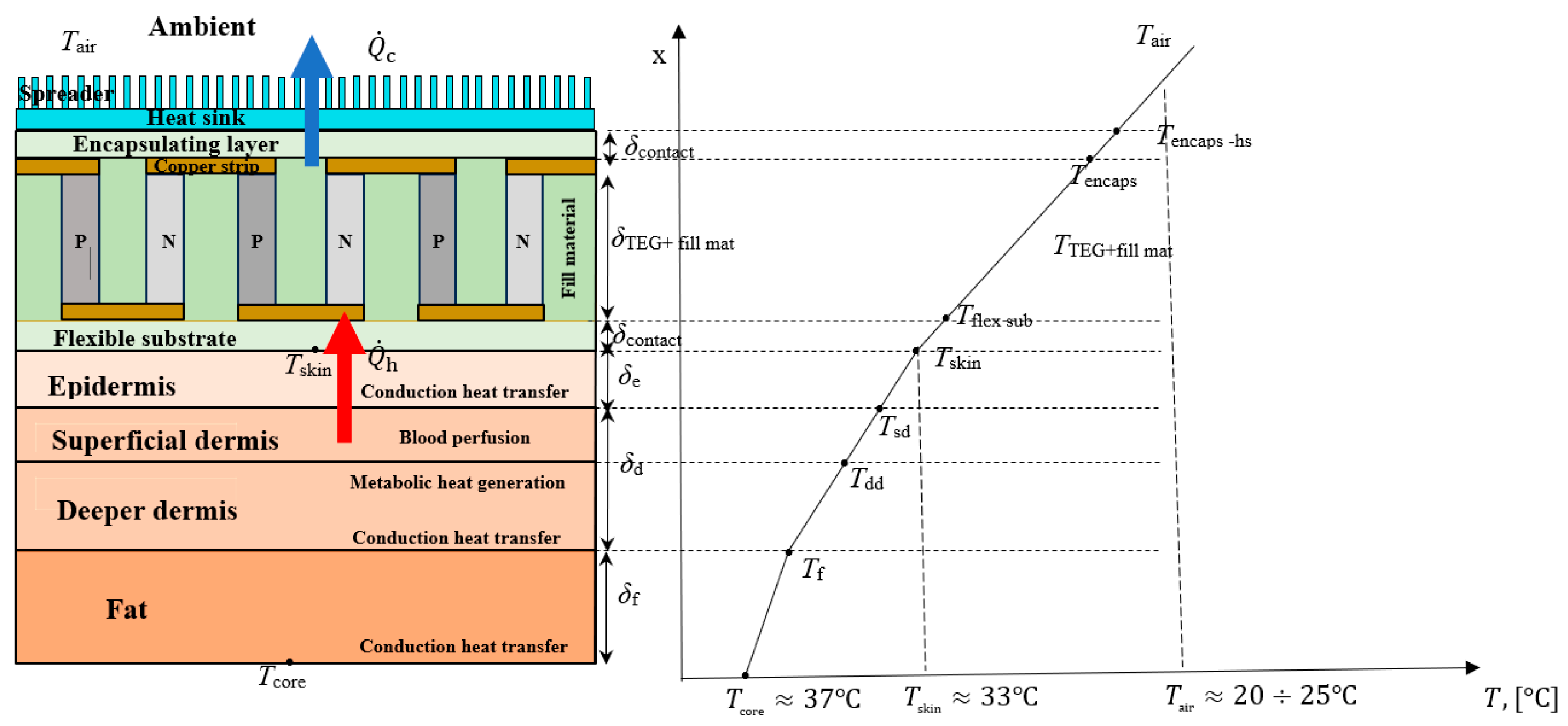
In the development of analytical heat transfer equations related to the interaction between human skin and w-TEG, the human skin is considered a quasi-homogeneous structure with three layers, in which each layer has its own thermal conductivity (as shown in Figure 2). The deepest layer is fat, followed by the dermis, and finally, the outer layer is the epidermis [75].
The general differential heat conduction equation used to describe the temperature distribution within biological tissues, including the human skin, when subject to heat sources is given by the Pennes bioheat equation [76] having the basic form as described in Equation (28):
where is the Laplacian of temperature, is the thermal conductivity of the tissue, is heat generation due to metabolic activity, such as cellular metabolism, is convective heat transfer due to blood perfusion (it considers the convective heat transfer between blood vessels and surrounding tissue), is the thermal diffusivity and quantifies how quickly heat is conducted through a material compared to how quickly it is stored or accumulated within the material, is the tissue density, is the specific heat capacity of the tissue at constant pressure, is the tissue temperature, and is the time.
The general differential heat conduction equation for the steady-state conditions within a multilayer structure with three layers, for one-dimensional geometry, is reduced to:
where represents the second spatial derivative of temperature with respect to the spatial coordinate within of the specific layer (such as fat, dermis and epidermis), is the thermal conductivity of the specific layer , , is the blood density, is the specific heat capacity of the blood at constant pressure, and is the blood perfusion rate that quantifies the rate at which blood circulates through a particular region of tissue (the blood perfusion rate can vary considerably and plays a crucial role in regulating the body’s temperature), is the rate of blood flow through a particular region of tissue, is the volume of the tissue through which the blood is flowing, is the time duration over which the blood flow is being considered. When the blood flow through the skin increases, it is called vasodilation, and when it decreases it, is referred to as vasoconstriction [77]). Moreover, is the tissue volume within the considered region, is the volume flow rate of blood, is the time interval over which the blood flow is measured, is the body core temperature, and is the temperature of the skin.
In the thermal analysis of fat and epidermis layers, the influence of blood perfusion is not considered, resulting in . In this case, the influence of the blood perfusion is found only in dermis (second layer), and Equation (23) becomes [75]:
To solve the second-order derivative Equation (30) with respect to the variable x, this equation is integrated twice, taking into account the integration constants and that arise in the integration process.
For fat and epidermis, the solutions of the temperature field in each skin tissue take the form of quadratic equations:
For dermis, the solution of the temperature field is more complex and involves exponential terms:
where .
3.2. Wearable TEG as a Thermal Load
In a w-TEG, the extrinsic temperature gradient between the body core and the ambient air , results in a constant heat flux through the w-TEG. This heat flux leads to an intrinsic temperature gradient across the hot and cold sides of the w-TEG legs, which in turn produces an output voltage due to the Seebeck effect [78].
The intrinsic temperature gradient is expressed as [70]:
where is the thermal resistance of the w-TEG, is the thermal contact resistance between the skin body and the w-TEG, and is the convective thermal resistance of the surrounding air. All resistances are in K/W.
The thermal resistance of the w-TEG is given by [79]:
where k is the thermal conductivity of the thermoelectric legs and FF is the fill factor (the ratio between the area of the thermoelectric legs to the total surface area of the w-TEG).
Effectively extracting heat from the human body depends on maximizing intrinsic temperature difference. This proves to be a challenging task because other parasitic thermal resistances make it hard for the heat to flow, namely: (i) the thermal resistance between the body core and w-TEG, due to the body skin, known as a thermal insulator; (ii) the contact thermal resistance between the skin interface and w-TEG due to the skin roughness; and (iii) the convective thermal resistance at the interface between the w-TEG and the surrounding air. The convective thermal resistance at the interface between the w-TEG and surrounding air is the dominant thermal resistance if no heat sink is used at the cold side of the w-TEG [19]. However, if the w-TEG is to be used on the human body, it is favorable not to use a bulky heat sink or to use a heat sink with a small design while achieving an acceptable heatsink resistance at this interface. In this case, the heat sink must be compact, not too large or bulky, to be suitable for use on the human body without causing discomfort [78]. Enhancing the overall performance of a w-TEG is achievable through the incorporation of heat spreaders. A heat spreader offers the advantage of reduced weight and increased flexibility compared to a finned heat sink, which is particularly beneficial for wearable applications. The utilization of high thermal conductivity heat spreaders on both the cold and hot sides of a w-TEG can effectively boost the power output [19].
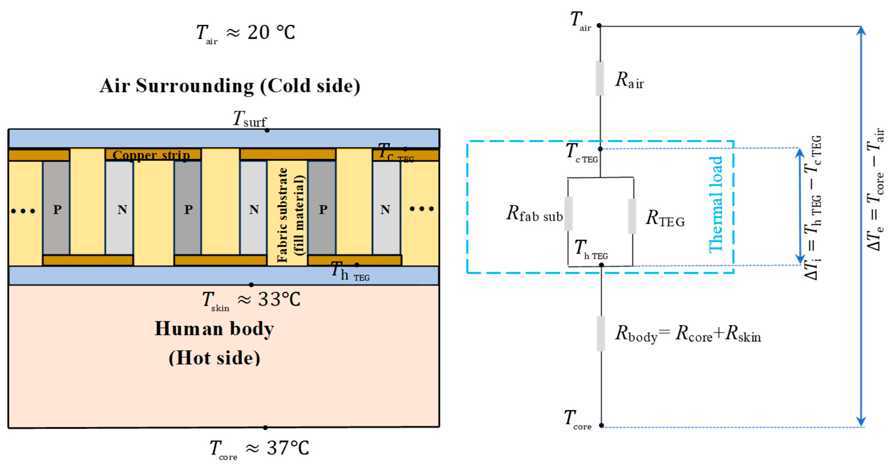
When a w-TEG is in contact with the skin, on the one hand the w-TEG limits the heat transfer from the body to the surrounding air, acting as a thermal barrier. On the other hand, at the same time the w-TEG absorbs heat from the skin to generate electricity, acting as a thermal load. Figure 3 shows the thermal circuit, with indicative values of the temperatures for air, skin, and core.
The simplified model of the thermal circuit is presented [70,80]. The optimal thermal resistance of the thermal circuit is defined as follows:
where is the parasitic thermal resistance due to the fabric material, which is in parallel with the total thermal resistance of the w-TEG with n thermoelements; is the thermal resistance between the body core and the skin surface; and is the thermal resistance of the surrounding air.
Nevertheless, the thermal resistance of the thermoelectric components is variable as a result of the Peltier effect during w-TEG operation. For this reason, it is proposed to consider an effective thermal conductivity concept when calculating the thermal resistance of the w-TEG, as provided in the following equation [81]:
where k is the thermal conductivity, L is the thermoelement leg length, and S is the thermoelement area.
The thermal contact resistance at the interface where the w-TEG contacts the human skin has a big impact on how well the w-TEG operates. High thermal contact resistance can impede the heat flow from the skin to the w-TEG. This means that less heat is utilized for electricity generation, reducing the w-TEG conversion efficiency. Reducing thermal contact resistance through improved materials or TEG design can enhance the module performance by allowing for more efficient heat transfer, thus increasing the amount of electricity generated from the human body heat. The w-TEGs must possess flexibility to ensure they establish conformal contact and minimize thermal resistance at the skin/w-TEG interface when integrated into a self-powered wearable electronic system [75].
The resistance at the point of contact should be measured between the skin and the w-TEG surface being explored. The thermal contact resistance model utilized by Benali-Khoudja and colleagues [82] in the development of their thermal display is derived from the model originally proposed in [83]. This model considered various factors including mechanical, thermophysical, and surface properties. In the absence of any fluid in the interfacial gap, the thermal contact conductance at the skin and w-TEG interface can be expressed as follows [84,85]:
where is the thermal contact resistance, is the heat transfer coefficient; is the harmonic mean thermal conductivity for solid 1 (epidermis) and solid 2 () with ; is the effective root mean square roughness, with the relation ; is effective absolute average surface asperity slope with ; is the contact pressure; is the microhardness of the softer material (epidermis); and is the cross-section area of skin tissues [75].
3.3. Analytical Heat Transfer Equations Related to Wearable TEG
In order to streamline the analysis, it is assumed that both P-type and N-type legs possess symmetric material properties and dimensions. Consequently, the subsequent theoretical analysis focuses solely on the P-type thermoelement [75]. The temperature distribution in the thermoelements for the steady state is expressed as follows:
where is the electric current that flows in the w-TEG, and , , are the electric resistance, thermal conductance, and thermal resistance of the P-type thermoelectric leg, respectively.
It is important to highlight that, in contrast to thermoelectric legs, the Joule heat generation in metallic electrodes is negligible, as presented in [75].
The electric current does not flow through the flexible layers and in this case, its value is . In this condition, Equation (41) becomes:
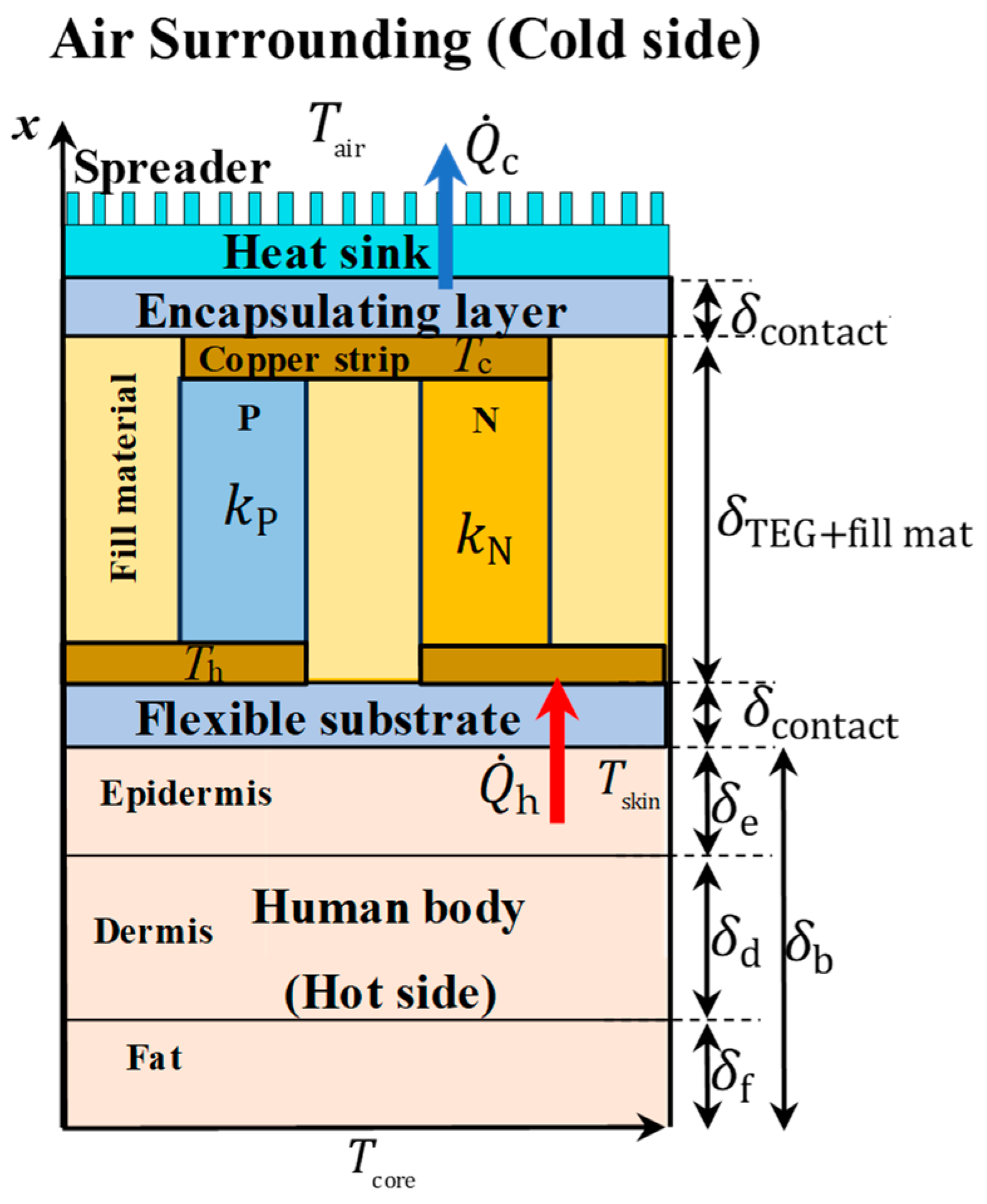
where “n” represents three combinations: for the flexible substrate and the skin/w-TEG interface, for the N-type and P-type thermoelectric legs and the fill material, and for the encapsulating layer and the spreader at the heat sink (Figure 4).
As the thermal resistances of the thermoelectric legs and fill material are connected in parallel, the effective thermal conductivity is calculated as follows:
where is the thermal conductivity of the P-type thermoelement, is the thermal conductivity of the fill material, and FF is the fill factor.
The temperature field distribution in the w-TEG and fill material satisfies the following equation:
where the constants and are:
where is thermal conductance of the N-type thermoelectric leg, is thermal conductance of the P-type thermoelectric leg, is the thermal conductance of the fill material, is the electrical resistance of the TEG thermoelements.
The heat flux that is absorbed at the skin–w-TEG interface including the flexible substrate is:
where is the equivalent thermal conductance between the thermal contact conductance, at the skin and w-TEG interface (as expressed in Equation (37)), and the thermal conductance of the flexible substrate .
The heat flux that is released through the encapsulating layer including the spreader at the heat sink is:
where is the equivalent thermal conductance between the encapsulating layer and the thermal conductance of the spreader at the heat sink, is the thermal conductivity of the encapsulating layer, is the convective coefficient of the air, and and are the cross-sectional area for the encapsulating layer and for the spreader, respectively.
According to the steady-state energy conservation law, heat flow rates must remain continuous at the interfaces between various components, including fat, dermis, epidermis, substrate, thermoelectric legs (including fill material), and the encapsulating layer [75,86]. In this case: ; ; ; ; . These conditions are necessary to obtain the expressions of the temperatures for the hot and cold sides of the w-TEG, and as well as the temperatures , , and at the interfaces of the skin tissues, as shown in Table 6 [75].
3.4. Evaluation of the w-TEG Performance
The performance analysis of w-TEG involves a detailed examination of the power output generated using the temperature differential between the heat source and heat sink [75,86,87]. The power output is calculated due to the principle of energy conservation and is evaluated as:
where is the Seebeck coefficient.
When an external load resistance RL is introduced, the power output can be written as follows:
The expression for the electric current is obtained by setting Equation (46) equal to Equation (47):
The substitution of the expressions of the temperatures and indicated in Table 6 in Equation (48) results in a third-degree equation with the electric current as the unknown [75,86,87]:
where the parameters , , , and are known and have the following expressions [75]:
The solution of Equations (49) and (52) has the following form:
with , , and .
The power output is calculated by replacing Equation (54) into Equation (47). In addition, the power density of the w-TEG refers to the amount of electrical power produced by the w-TEG per unit area. The power density is the ratio between the power output generated by the w-TEG to the surface area S over which the TEG is distributed or attached:
The performance of a w-TEG is influenced by various parameters, including external load resistance , human body skin, thermoelectric couple height, and fill factor FF. Zhang et al. [87] investigated the influence of these parameters on the performance of w-TEG. The research conducted in [87] highlights the significance of these parameters in optimizing the performance of w-TEG devices. Understanding how factors such as the thermophysical properties of the filler material, human body skin, fill factor, thermal convective boundary conditions, and the figure of merit of thermoelectric legs (ZT) influence the external load resistance can lead to the development of more efficient and practical w-TEG systems, with potential benefits in energy harvesting, waste heat recovery, and sustainable power generation. The metabolic heat generated has very little effect on the power density of the skin-w-TEG system, even when the metabolic heat generation increases significantly. Conversely, the blood perfusion rate within the skin tissue plays a key role in enhancing the w-TEG performance, with power density increasing significantly as the blood perfusion rate rises. Therefore, effective management and optimization of the w-TEG should consider blood perfusion as a crucial factor. The influence of convective heat transfer between the w-TEG’s lateral surfaces and the ambient surroundings significantly impacts the temperature drop (ΔT) and power density of the w-TEG. The influence of convective heat transfer on a w-TEG’s lateral surfaces is essential because it determines how effectively the w-TEG can maintain the necessary temperature gradient for efficient electricity generation. If convective heat transfer is not considered or optimized, it can lead to reduced performance and power output of the w-TEG. Also, the influence of convective heat transfer at the heat sink and contact pressure between human skin and w-TEG significantly affects temperature drop and power density. Increasing contact pressure causes the human body’s skin to deform. Since the human body’s skin is generally softer than the flexible substrate of the w-TEG, this deformation can effectively increase the actual contact area with the substrate. This, in turn, reduces the contact thermal resistance, leading to more effective heat transfer. Concerning the influence of the height of the thermoelectric couples and the convective heat transfer coefficient, these significantly affect the temperature drop and power density of the w-TEG. Increasing the thermoelectric couple height improves the temperature drop but also raises the internal electric resistance, leading to an optimal height for maximum power density. Additionally, heat convection at lateral surfaces becomes more significant with higher thermoelectric couple heights.
In summary, the performance analysis of w-TEG involves evaluating the power output based on temperature gradients. Various factors, including external load resistance, human body skin, thermoelectric couple height, and fill factor, significantly impact the w-TEG performance. Understanding these parameters is crucial for optimizing w-TEG systems. Additionally, the influence of metabolic heat generation and blood perfusion within the skin tissue should be considered. Convective heat transfer between w-TEG lateral surfaces and the surroundings also affects temperature and power density. Optimizing contact pressure and managing thermocouple height are key factors for maximizing power density. These insights are essential for enhancing w-TEG design and applications.
4. Wearable Thermoelectric Devices for Personal Thermal Management
Personal thermal management refers to the establishment of a satisfactory thermal environment around the human body, in which the individuals live and operate under acceptable thermal comfort conditions. The solutions for personal thermal management can be used to reduce the energy needed to heat or cool the internal environments in the buildings, concentrating the means for reaching satisfactory temperatures to the space close to the activity of the individuals [88].
There are various possibilities for impacting on the local thermal environment. The first category includes non-wearable solutions, which act on the forms of heat transfer that have an impact on the human body. These solutions (whose detailed analysis is outside the scope of this article) include, for example:
- ▪
- Thermally controlled chairs: thermoelectric devices are used in thermoelectrically heated and cooled chairs to have an influence on thermal sensation and comfort, as shown, for example, from the experiments presented in [89,90]. The thermal sensation can be improved when the temperature is outside the acceptable range, even though the effects of chair heating can be limited by the fact that the thermal sensation of the extremities cannot be improved to a significant extent [91].
- ▪
- Systems for local heating, ventilation, and air conditioning: portable solutions have been developed for heating or cooling the local environment and interact with the thermoregulation of the human body [92]. For example, a thermoelectric air conditioning undergarment solution that provides personal heating or personal cooling depending on the control mode with air volume control is illustrated in [93]. The system contains a power-supplied micro-blower that heats up or cools down the air in the local ambient and uses a system with small tubes to send the air to various parts of the human body.
The other category, which is of interest for this section, is the one of wearable solutions, consisting of thermoregulated clothing of different types. Traditional thermoelectric devices are generally based on inorganic thermoelectric devices—which are rigid, have poor mechanical properties, and are expensive—so that they can be applied to localized solutions (e.g., sensors) more than for clothing purposes [94]. For the diffusion of wearable thermoelectric solutions for clothing, the main aspect is the development of flexible devices, which can adapt to the movements of the human body [95] or can be easily stretched [96] and are composed of sections that are simply reconfigurable [97]. In particular, flexible thermoelectric devices based on organic composites, such as polymer materials [94], are interesting because of their specific properties of flexibility, low toxicity, low cost, and stability at relatively high temperatures, even though their efficiency is lower than the that obtained with inorganic materials [98]. The development of organic–inorganic composite thermoelectric devices and other hybrid solutions [99] is promising, with the possibility of benefitting from the best properties of the different materials and providing cost-effective applications [100]. In the evolution in progress on the materials side, promising solutions are expected from film-based thermoelectric modules, because of significant performance, high scalability, and opportunities for largescale production [101].
For the development of wearable solutions, the expressions indicated in the previous sections illustrate the basic heat transfer principles referring to the interactions between the human body and the wearable TEG. In particular, the skin thermal resistance is higher than the TEG resistance and plays a considerable role in wearable applications. Further practical aspects depend on body comfort. Generally, wearable solutions are acceptable if their size and weight are limited. For this purpose, the preferred solutions have lower thermal conductivity of the material that forms the thermoelectric legs, in such a way that a thinner TEG can be constructed by maintaining a relatively large temperature difference.
Moreover, in some practical applications, the use of a heat sink is avoided because of esthetic or space reasons. However, without a heat sink, the power density that can be obtained from a wearable TEG is generally limited with respect to the power density obtained from a wearable TEG with heat sink. For wearable TEG applications, solutions that use a flat thermal spreader to replace the heat sink can be more adaptable. Even though in general the thermal spreader could be less efficient than a heat sink for dissipating heat, the w-TEG presented in [8] with a flat thermal spreader reached a 30% power density increase with respect to the best reported TEG with heat sinks.
Active and passive thermal management methods have been categorized [102] for wearable solutions referring to heating or cooling modes, as follows:
- ▪
- Active methods: in general, thermoelectric devices can be used for cooling and heating, as well as electro- and magnetocaloric cooling and heating. For active heating, the typical source is Joule heating, and for active cooling the active microfluidic cooling is adopted. Regarding active heating, thermoelectric textiles based on the Peltier effect, in which flexible thermoelectric devices are integrated into the textiles to provide power generation, can be more efficient than Joule heating textiles [103]. For active cooling with thermoelectric devices, typically, the circulation of water in a copper tube is added for improving the heat exchange; the cooling output that can be provided is relatively low, due to the low coefficient of performance, and could be enhanced with the use of multistage thermoelectric modules [104]. An effective solution for a wearable solution with a thermoelectric device that does not use a water heat sink and can produce a cooling effect of more than 10 °C by maintaining a relatively high coefficient of performance is presented in [105].
- ▪
- Passive methods: in general, heat storage from the external environment is obtained with materials having high latent heat or high heat capacity to store and release heat as needed. Further methods include thermal insulation to minimize the heat transfer with respect to the human skin. For passive heating purposes, thermally conductive materials are used to enhance the heat exchange with the air, or photothermal materials are used to absorb solar energy to warm the human skin. For passive cooling purposes, radiative cooling materials are used to refrigerate the human skin, and evaporative cooling materials facilitate the transition from liquid to vapor. Passive methods are not based on thermoelectric devices.
The wearable solutions can be partitioned, for example, into:
- ▪
- Natural heat exchange: these solutions focus on natural heat exchange and energy harvesting and aim to harness the body’s natural heat production and the surrounding environment to maintain thermal comfort.
- ▪
- Assisted heat exchange: these solutions adopt clothing enhancements and include additional parts with fans for better air circulation, or in other cases water circulation systems for making the temperatures in the different parts of the clothing more uniform. The effectiveness of these solutions could depend on the type of activity carried out by the individual in the living environment. For example, the extra devices that allow for assisted heat exchange could add weight or size to the clothing, potentially reducing the mobility of the individuals when carrying out certain activities.
From another point of view, the devices used in the wearable solutions can be categorized into:
- ▪
- Autonomous devices: self-powered solutions in which there is no energy input from external sources. These solutions rely on internal energy sources to regulate temperature and maintain thermal comfort.
- ▪
- Non-autonomous devices: solutions for which an energy input is needed from external sources. These solutions require a continuous supply of energy to function and regulate temperature effectively.
- ▪
- Hybrid devices: These combine nonautonomous and autonomous devices in different parts of the wearable solutions. Some parts of the clothing may operate autonomously while others rely on external energy sources. This hybrid approach offers flexibility in managing thermal comfort. The review presented in [106] addresses many cases of personal comfort devices and indicates an energy efficient solution with combined use of air-cooling units and a thermoelectric cooling unit with limited surface coverage.
A further distinction refers to the type of contact of the thermoelectric devices with the human body, which is an important aspect that also affects the choice of the materials and of the modes for connecting the devices to the human body:
- ▪
- For direct contact with the human body, the main solutions include cooling vests with the thermoelectric device in contact with human skin [105]. A key aspect is to avoid the contact of the human body with rare or toxic elements that can be found in some thermoelectric devices (e.g., bismuth, lead, or tellurium) [107]. Biobased thermoelectric materials (such as cotton, cellulose, or lignin), which have less impact on the human body, can be used as a substrate for constructing wearable devices.
- ▪
- Without direct contact with the human body (i.e., with indirect contact), the heat transfer modes have to be studied by considering the materials used for clothing. The use of flexible and long thermoelectric fibers is an effective solution for covering the various possible curvatures of the surfaces, enhancing thermal management and comfort [108].
In summary, personal thermal management is a multifaceted field with a wide range of solutions for enhancing thermal comfort and energy efficiency. These solutions can range from nonwearable solutions that affect heat transfer around the human body to wearable solutions, including thermoregulated clothing. The advancement in materials and technology has enabled the development of flexible and efficient thermoelectric devices that can be integrated into clothing, offering active and passive thermal management methods. Furthermore, the choice between autonomous, nonautonomous, or hybrid devices, as well as the consideration of direct or indirect contact with the human body, provides a wide array of options for tailoring personal thermal management solutions to individual needs and preferences. The exploration of these possibilities holds promise for improving comfort and wellbeing of individuals, while reducing energy consumption in various environments.
5. Conclusions
Technological development in the thermoelectric generation area is providing interesting solutions to create better local thermal environments for individuals who carry out activities in indoor environments. This paper addressed wearable thermoelectric generators that interact with the human body to improve local thermal comfort and increase energy efficiency by reducing, to a certain extent, the need for heating or cooling the ambient. The analysis of the heat transfer mechanisms that appear in the interaction between thermoelectric devices and the human body was discussed as a crucial step for understanding how the human thermoregulatory system can respond in the presence of wearable thermoelectric generators that consider the body as a heat source. Moreover, the review presented in this paper summarized how conductive, convective, and radiative heat transfer, together with evaporation at the skin surface, impact on the temperature regulation of the skin, which is the surface of contact between the human body and thermoelectric devices. Furthermore, the materials, flexibility, and efficiency of wearable thermoregulated clothing that can be used to create a comfortable thermal environment around the human body were considered, also categorizing their active and passive modes of operation.
Wearable thermoelectric generators are versatile and adaptable solutions to address individual thermal needs in local environments. The main directions for the future are the development of thermoelectric materials with enhanced thermal performance and the design of structurally flexible, lightweight, and cost-effective solutions able to enhance the interaction with the human body considering situations with parts of the body in movement. On the materials side, biobased materials and organic composites are of interest because of their low environmental impact. Thermal performance refers to the efficiency of the energy conversion, for which the use of multistage thermoelectric modules and the exploitation of smart sensors and control systems can provide more adaptive thermal regulation.
The evolution of wearable thermoelectric generation technologies and application requires multidisciplinary collaborations between experts of different domains, such as materials science, thermal engineering, environmental engineering, physiology, psychology, up to clothes design, for merging their competences in the direction of providing more comfortable, energy efficient, cost-effective, and practically appealing solutions.
Funding
This research received no external funding.
Data Availability Statement
No new data were created or analyzed in this study.
Conflicts of Interest
The author declares no conflicts of interest.
References
- Hasan, M.N.; Sahlan, S.; Osman, K.; Ali, M.S.M. Energy harvesters for wearable electronics and biomedical devices. Adv. Mater. Technol. 2021, 6, 2000771. [Google Scholar] [CrossRef]
- Enescu, D. Book Chapter “Thermoelectric energy harvesting: Basic Principles and Applications”. In Green Energy Advances; Enescu, D., Ed.; InTech Publishing: Rijeka, Croatia, 2019; pp. 1–37. [Google Scholar]
- Du, Y.; Xu, J.; Paul, B.; Eklund, P. Flexible thermoelectric materials and devices. Appl. Mater. Today 2018, 12, 366–388. [Google Scholar] [CrossRef]
- He, J.; Li, K.; Jia, L.; Zhu, Y.; Zhang, H.; Linghu, J. Advances in the applications of thermoelectric generators. Appl. Therm. Eng. 2024, 236, 121813. [Google Scholar] [CrossRef]
- Siddique, A.R.M.; Mahmud, S.; Heyst, B.V. A review of the state of the science on wearable thermoelectric power generators (TEGs) and their existing challenges. Renew. Sustain. Energy Rev. 2017, 73, 730–744. [Google Scholar] [CrossRef]
- Sahin, A.Z.; Yilbas Bekir, S. The thermoelement as thermoelectric power generator: Effect of leg geometry on the efficiency and power generation. Energy Convers Manag. 2013, 65, 26–32. [Google Scholar] [CrossRef]
- Francioso, L.; De Pascali, C.; Farella, I.; Martucci, C.; Cretì, P.; Siciliano, P.; Perrone, A. Flexible thermoelectric generator for ambient assisted living wearable biometric sensors. J. Power Sources 2011, 196, 3239–3243. [Google Scholar] [CrossRef]
- Nozariasbmarz, A.; Suarez, F.; Dycus, J.H.; Cabral, M.J.; LeBeau, J.M.; Öztürk, M.C.; Vashaee, D. Thermoelectric generators for wearable body heat harvesting: Material and device concurrent optimization. Nano Energy 2020, 67, 104265. [Google Scholar] [CrossRef]
- Shi, Y.; Wang, Y.; Mei, D.; Chen, Z. Wearable Thermoelectric Generator with Copper Foam as the Heat Sink for Body Heat Harvesting. IEEE Access 2018, 6, 43602–43611. [Google Scholar] [CrossRef]
- Zoui, M.A.; Bentouba, S.; Stocholm, J.G.; Bourouis, M. A Review on Thermoelectric Generators: Progress and Applications. Energies 2020, 13, 3606. [Google Scholar] [CrossRef]
- Yuan, J.; Zhu, R.; Li, G. Self-powered electronic skin with multisensory functions based on thermoelectric conversion. Adv. Mater. Technol. 2020, 5, 000419. [Google Scholar] [CrossRef]
- Kim, J.; Khan, S.; Wu, P.; Park, S.; Park, H.; Yu, C.; Kim, W. Self-charging wearables for continuous health monitoring. Nano Energy 2021, 79, 105419. [Google Scholar] [CrossRef]
- Hasan, M.N.; Asri, M.I.A.; Saleh, T.; Muthalif, A.G.A.; Ali, M.S.M. Wearable thermoelectric generator with vertically aligned PEDOT:PSS and carbon nanotubes thermoelements for energy harvesting. Int. J. Energy Res. 2022, 46, 15824–15836. [Google Scholar] [CrossRef]
- Kim, C.S.; Yang, H.M.; Lee, J.; Lee, G.S.; Choi, H.; Kim, Y.J.; Lim, S.H.; Cho, S.H.; Cho, B.J. Self-powered wearable electrocardiography using a wearable thermoelectric power generator. ACS Energy Lett. 2018, 3, 501–507. [Google Scholar] [CrossRef]
- Lee, B.B.; Cho, H.; Park, K.T.; Kim, J.-S.; Park, M.; Kim, H.; Hong, Y.; Chung, S. High-performance compliant thermoelectric generators with magnetically self-assembled soft heat conductors for self-powered wearable electronics. Nat. Commun. 2020, 11, 1. [Google Scholar] [CrossRef]
- Kong, D.; Zhu, W.; Guo, Z.; Deng, Y. High-performance flexible Bi2Te3 films based wearable thermoelectric generator for energy harvesting. Energy 2019, 175, 292–299. [Google Scholar] [CrossRef]
- Khan, S.; Kim, J.; Roh, K.; Park, G.; Kim, W. High power density of radiative-cooled compact thermoelectric generator based on body heat harvesting. Nano Energy 2021, 87, 106180. [Google Scholar] [CrossRef]
- Choi, H.; Kim, Y.J.; Song, J.; Kim, C.S.; Lee, G.S.; Kim, S.; Park, J.; Yim, S.H.; Park, S.H.; Hwang, H.R.; et al. UV-curable silver electrode for screen-printed thermoelectric generator. Adv. Funct. Mater. 2019, 29, 1901505. [Google Scholar] [CrossRef]
- Nozariasbmarz, A.; Collins, H.; Dsouza, K.; Polash, M.H.; Hosseini, M.; Hyland, M.; Liu, J.; Malhotra, A.; Ortiz, F.M.; Mohaddes, F.; et al. Review of wearable thermoelectric energy harvesting: From body temperature to electronic systems. Appl. Energy 2020, 258, 114069. [Google Scholar] [CrossRef]
- Nandihalli, N.; Liu, C.-J.; Mori, T. Polymer based thermoelectric nanocomposite materials and devices: Fabrication and characteristics. Nano Energy 2020, 78, 105186. [Google Scholar] [CrossRef]
- Francioso, L.; De Pascali, C. Chapter 10 Thermoelectric Energy Harvesting for Powering Wearable Electronics. In Thermoelectric Energy Conversion: Basic Concepts and Device Applications, 1st ed.; Dávila Pineda, D., Alireza Rezania, A., Eds.; Wiley-VCH: Weinheim, Germany, 2017; pp. 205–231. [Google Scholar]
- Kim, G.H.; Shao, L.; Zhang, K.; Pipe, K.P. Engineered doping of organic semiconductors for enhanced thermoelectric efficiency. Nat. Mater. 2013, 12, 719. [Google Scholar] [CrossRef]
- de Fazio, R.; Cafagna, D.; Marcuccio, G.; Minerba, A.; Visconti, P. A Multi-Source Harvesting System Applied to Sensor-Based Smart Garments for Monitoring Workers’ Bio-Physical Parameters in Harsh Environments. Energies 2020, 13, 2161. [Google Scholar] [CrossRef]
- Tanwar, A.; Lal, S.; Razeeb, K. Structural Design Optimization of Micro-Thermoelectric Generator for Wearable Biomedical Devices. Energies 2021, 14, 2339. [Google Scholar] [CrossRef]
- Enescu, D. Models and Indicators to Assess Thermal Sensation Under Steady-state and Transient Conditions. Energies 2019, 12, 841. [Google Scholar] [CrossRef]
- Lai, D.T.H.; Palaniswami, M.; Begg, R. Healthcare Sensor Networks: Challenges toward Practical Implementation; CRC Press, Taylor & Francis Group: Boca Raton, FL, USA, 2016; 462p. [Google Scholar]
- Merriam-Webster Dictionary, “Thermal Inertia”. Available online: https://www.merriam-webster.com/dictionary/thermal%20inertia (accessed on 28 November 2023).
- Houdas, Y.; Ring, E.F.J. Human Body Temperature: Its Measurement and Regulation; Springer Science & Business Media: New York, NY, USA, 2013; 238p. [Google Scholar]
- Kuwabara, K.; Mochida, T.; Nagano, K.; Shimakura, K. Experiments to determine the convective heat transfer coefficient of a thermal manikin. Elsevier Ergon. Book Series 2005, 3, 423–429. [Google Scholar]
- de Dear, R.J.; Arens, E.; Hui, Z.; Oguro, M. Convective and radiative heat transfer coefficients for individual human body segments. Int. J. Biometeorol. 1997, 40, 141–156. [Google Scholar] [CrossRef] [PubMed]
- Oliveira, A.V.; Gaspar, A.R.; Francisco, S.C.; Quintela, D.A. Convective heat transfer from a nude body under calm conditions: Assessment of the effects of walking with a thermal manikin. Int. J. Biometeorol. 2012, 56, 319–332. [Google Scholar] [CrossRef] [PubMed]
- Cena, K.; Clark, J.A. Bioengineering, Thermal Physiology, and Comfort; Elsevier: Amsterdam, The Netherlands, 1981. [Google Scholar]
- Psikuta, A.; Kuklane, K.; Bogdan, A.; Havenith, G.; Annaheim, S.; Rossi, R.M. Opportunities and constraints of presently used thermal manikins for thermo-physiological simulation of the human body. Int. J. Biometeorol. 2015, 60, 435–446. [Google Scholar] [CrossRef]
- Xu, J.; Psikuta, A.; Li, J.; Annaheim, S.; Rossi, R.M. Influence of human body geometry, posture and the surrounding environment on body heat loss based on a validated numerical model. Build. Environ. 2019, 166, 106340. [Google Scholar] [CrossRef]
- Fanger, P.O. Thermal Comfort; Danish Technical Press: Copenhagen, Denmark, 1970. [Google Scholar]
- Quintela, D.; Gaspar, A.; Borges, C. Analysis of sensible heat exchanges from a thermal manikin. Eur. J. Appl. Physiol. 2004, 92, 663–668. [Google Scholar] [CrossRef]
- Kurazumi, Y.; Tsuchikawab, T.; Ishiia, J.; Fukagawaa, K.; Yamatoc, Y.; Matsubarad, N. Radiative and convective heat transfer coefficients of the human body in natural convection. Build. Environ. 2008, 43, 2142–2153. [Google Scholar] [CrossRef]
- Nielsen, M.; Pedersen, L. Studies on the heat loss by radiation and convection from the clothed human body. Acta Physiol. Scand. 1953, 27, 272–294. [Google Scholar] [CrossRef] [PubMed]
- Oguro, M.; Arens, E.; de Dear, R.; Zhang, H.; Katayama, T. Convective heat transfer coefficients and clothing insulations for parts of the clothed human body under calm conditions. J. Archit. Plan. Environ. Eng. 2002, 561, 31–39. [Google Scholar]
- Omori, T.; Yang, J.H.; Kato, S.; Murakami, S. Coupled simulation of convection and radiation on thermal environment around an accurately shaped human body. In Proceedings of the RoomVent 2004, 9th International Conference on Air Distribution in Rooms, Coimbra, Portugal, 5–8 September 2004. [Google Scholar]
- Sparrow, E.M.; Eichhorn, R.; Gregg, J.L. Combined forced and free convection in a boundary layer flow. Phys. Fluids 1959, 2, 319. [Google Scholar] [CrossRef]
- Gao, S.; Ooka, R.; Oh, W. Formulation of human body heat transfer coefficient under various ambient temperature, air speed and direction based on experiments and CFD. Build. Environ. 2019, 160, 106168. [Google Scholar] [CrossRef]
- Colin, J.; Houdas, Y. Experimental determination of coefficient of heat exchanges by convection of human body. J. Appl. Physiol. 1967, 22, 31–38. [Google Scholar] [CrossRef] [PubMed]
- Yu, Y.; Liu, J.; Chauhan, K.; de Dear, R.; Niu, J. Experimental study on convective heat transfer coefficients for the human body exposed to turbulent wind conditions. Build. Environ. 2020, 169, 106533. [Google Scholar] [CrossRef]
- Winslow, C.-E.A.; Gagge, A.P.; Herrington, L.P. The influence of air movement on heat losses from the clothed human body. J. Physiol. 1939, 127, 505–515. [Google Scholar] [CrossRef]
- Gagge, A.P.; Fobelets, A.P.; Berglund, L.G. A standard predictive index of human response to the thermal environment. ASHRAE Trans. 1986, 92, 709–731. [Google Scholar]
- Nishi, Y.; Gagge, A.P. Direct evaluation of convective heat transfer coefficient by naphthalene sublimation. J. Appl. Physiol. 1970, 29, 830–838. [Google Scholar] [CrossRef]
- Seppänen, O.; McNall, P.E.; Munson, D.M.; Sprague, C.H. Thermal insulating values for typical indoor clothing ensembles. ASHRAE Trans. 1972, 78, 120–130. [Google Scholar]
- Kerslake, D.M.K. The Stress of Hot Environments; Cambridge University Press: Cambridge, UK, 1972. [Google Scholar]
- Missenard, F.A. Coefficients d’échange de chaleur du corps humain per convection, en function de la position, de l’activité du sujet et de l’environment. (In French): Heat Exchange Coefficients of the Human Body by Convection, as a Function of Position, Subject’s Activity, and Environment. Arh. Sci. Physiol. 1973, 27, A45–A50. [Google Scholar]
- Mitchell, D. Convective heat transfer from man and other animals. In Heat Loss from Animals and Man; Monteith, J.L., Mount, L.E., Eds.; Elsevier: London, UK, 1974; pp. 59–76. [Google Scholar]
- Fukazawa, T.; Tochihara, Y. The thermal manikin: A useful and effective device for evaluating human thermal environments. J. Human-Environ. Syst. 2015, 18, 21–28. [Google Scholar] [CrossRef]
- Fu, M.; Weng, W.; Chen, W.; Luo, N. Review on modeling heat transfer and thermoregulatory responses in human body. J. Therm. Biol. 2016, 62 Pt B, 189–200. [Google Scholar] [CrossRef]
- Luo, N.; Weng, W.G.; Fu, M. Theoretical analysis of the effects of human movement on the combined free-forced convection. Int. J. Heat Mass Transf. 2015, 91, 37–44. [Google Scholar] [CrossRef]
- Li, C.; Ito, K. Numerical and experimental estimation of convective heat transfer coefficient of human body under strong forced convective flow. J. Wind Eng. Ind. Aerod. 2014, 126, 107–117. [Google Scholar] [CrossRef]
- Ichihara, M.; Saitou, M.; Tanabe, S.; Nishimura, M. Measurement of convective heat transfer coefficient and radiative heat transfer coefficient of standing human body by using thermal manikin. In Proceedings of the Annual Meeting of the Architectural Institute of Japan, Tokyo, Japan, August 1995; pp. 379–380. [Google Scholar]
- Oguro, M.; Arens, E.; de Dear, R.; Zhang, H.; Katayama, T. Convective heat transfer coefficients and clothing insulations for parts of the clothed human body under airflow conditions. J. Archit. Plan. Environ. Eng. AIJ 2002, 561, 21–29. [Google Scholar]
- Oliveira, A.V.M.; Gaspar, A.R.; Francisco, S.C.; Quintela, D.A. Analysis of natural and forced convection heat losses from a thermal manikin: Comparative assessment of the static and dynamic postures. J. Wind Eng. Ind. Aerod. 2014, 132, 66–76. [Google Scholar] [CrossRef]
- Ono, T.; Murakami, S.; Ooka, R.; Omori, T. Numerical and experimental study on convective heat transfer of the human body in the outdoor environment. J. Wind Eng. Ind. Aerodyn 2008, 96, 1719–1732. [Google Scholar] [CrossRef]
- Roth, M. Review of atmospheric turbulence over cities. Q. J. R. Meteorol. Soc. 2000, 126, 941–990. [Google Scholar] [CrossRef]
- Luo, N.; Weng, W.G.; Fu, M.; Yang, J.; Han, Z.Y. Experimental study of the effects of human movement on the convective heat transfer coefficient. Exp. Therm. Fluid Sci. 2014, 57, 40–56. [Google Scholar] [CrossRef]
- Fojtlín, M.; Fišer, J.; Jícha, M. Determination of convective and radiative heat transfer coefficients using 34-zones thermal manikin: Uncertainty and reproducibility evaluation. Exp. Therm. Fluid Sci. 2016, 77, 257–264. [Google Scholar] [CrossRef]
- Yang, J.; Zhang, S. Three-dimensional simulation of the convective heat transfer coefficient of the human body under various air velocities and human body angles. Int. J. Therm. Sci. 2023, 187, 108171. [Google Scholar] [CrossRef]
- Fanger, P.O. Thermal Comfort—Analysis and Applications in Environmental Engineering; McGraw-Hill: New York, NY, USA, 1972. [Google Scholar]
- Du Bois, D.; Du Bois, E.F. Clinical calorimetry: Tenth paper a formula to estimate the approximate surface area if height and weight be known. Arch. Intern. Med. 1916, 17, 863–871. [Google Scholar] [CrossRef]
- Kurazumi, Y.; Rezgals, L.; Melikov, A.K. Convective heat transfer coefficients of the human body under forced convection from ceiling. J. Ergonom. 2014, 4, 1000126. [Google Scholar] [CrossRef]
- Arens, E.; Zhang, H. The Skin’s Role in Human Thermoregulation and Comfort. In Thermal and Moisture Transport in Fibrous Materials; Pan, N., Gibson, P., Eds.; Woodhead Publishing Ltd.: Cambridge, UK, 2006; pp. 560–602. [Google Scholar]
- Berglund, L.G.; Gonzalez, R.R. Evaporation of sweat from sedentary man in humid environments. J. Appl. Physiol. 1977, 42, 767–772. [Google Scholar] [CrossRef] [PubMed]
- Leonov, V.; Vullers, R.J.M. Wearable thermoelectric generators for body-powered devices. J. Electron. Mater. 2009, 38, 1491–1498. [Google Scholar] [CrossRef]
- Huizenga, C.; Zhang, H.; Arens, E.; Wang, D. Skin and core temperature response to partial and whole-body heating and cooling. J. Therm. Biol. 2004, 29, 549–558. [Google Scholar] [CrossRef]
- Tanda, G. The Use of Infrared Thermography to Detect the Skin Temperature Response to Physical Activity. 33rd UIT (Italian Union of Thermo-fluid-dynamics) Heat Transfer Conference. J. Phys. Conf. Ser. 2015, 655, 012062. [Google Scholar] [CrossRef]
- Frank, S.M.; Raja, S.N.; Bulcao, C.F.; Goldstein, D.S. Relative contribution of core and cutaneous temperatures to thermal comfort and autonomic responses in humans. J. Appl. Physiol. 1999, 86, 1588–1593. [Google Scholar] [CrossRef]
- Zhang, H. Human Thermal Sensation and Comfort in Transient and Non-Uniform Thermal Environments. Ph.D. Thesis, CEDR, University of California at Berkeley, Berkeley, CA, USA, 2003. [Google Scholar]
- McIntyre, D.A. Indoor Climate; Applied Science Publishers: London, UK, 1980. [Google Scholar]
- Zhang, A.; Li, G.; Wang, B.; Wang, J. A Theoretical Model for Wearable Thermoelectric Generators Considering the Effect of Human Skin. J. Electron. Mater. 2021, 50, 1514–1526. [Google Scholar] [CrossRef]
- Pennes, H.H. Analysis of Tissue and Arterial Blood Temperatures in the Resting Human Forearm. J. Appl. Physiol. 1948, 1, 93. [Google Scholar] [CrossRef] [PubMed]
- Wijethunge, D.; Kim, D.; Kim, W. Simplified human thermoregulatory model for designing wearable thermoelectric devices. J. Phys. D Appl. Phys. 2018, 51, 055401. [Google Scholar] [CrossRef]
- Suarez, F.; Nozariasbmarz, A.; Vashaee, D.; Öztürk, M.C. Designing thermoelectric generators for self-powered wearable electronics. Energy Environ. Sci. 2016, 9, 2099–2113. [Google Scholar] [CrossRef]
- Yee, S.K.; LeBlanc, S.; Goodson, K.E.; Dames, C. $ per W metrics for thermoelectric power generation: Beyond ZT. Energy Environ. Sci. 2013, 6, 2561–2571. [Google Scholar] [CrossRef]
- Leonov, V. Thermoelectric energy harvester on the heated human machine. J. Micromech. Microeng. 2011, 21, 125013. [Google Scholar] [CrossRef]
- Baranowski, L.L.; Snyder, G.J.; Toberer, E.S. Effective thermal conductivity in thermoelectric materials. J. Appl. Phys. 2013, 113, 204904. [Google Scholar] [CrossRef]
- Benali-Khoudja, M.; Hafez, M.; Alexandre, J.M.; Benachour, J.; Kheddar, A. Thermal Feedback Model for Virtual Reality. In Proceedings of the International Symposium on Micromechatronics and Human Science, Nagoya, Japan, 19–22 October 2003; pp. 153–158. [Google Scholar]
- Yovanovich, M.M.; Antonetti, V.W. Application of Thermal Contact Resistance Theory to Electronic Packages. In Advances in Thermal Modeling of Electronic Components and Systems; Bar-Cohen, A., Kraus, A.D., Eds.; Hemisphere Publishing: New York, NY, USA, 1988. [Google Scholar]
- Ho, H.N.; Jones, L.A. Modeling the Thermal Responses of the Skin Surface During Hand-Object Interactions. J. Biomech. Eng.-T ASME 2008, 130, 021005. [Google Scholar] [CrossRef]
- Bejan, A.; Kraus, A.D. Heat Transfer Handbook; John Wiley & Sons, Inc.: Hoboken, NJ, USA, 2003. [Google Scholar]
- Pang, D.; Zhang, A.; Guo, Y.; Wu, J. Energy harvesting analysis of wearable thermoelectric generators integrated with human skin. Energy 2023, 282, 128850. [Google Scholar] [CrossRef]
- Zhang, A.; Pang, D.; Lou, J.; Wang, J.; Huang, W.M. An analytical model for wearable thermoelectric generators harvesting body heat: An opportunistic approach. Appl. Therm. Eng. 2024, 236, 121658. [Google Scholar] [CrossRef]
- Hu, R.; Liu, Y.; Shin, S.; Huang, S.; Ren, X.; Shu, W.; Cheng, J.; Tao, G.; Xu, W.; Chen, R.; et al. Emerging Materials and Strategies for Personal Thermal Management. Adv. Energy Mater. 2020, 10, 1903921. [Google Scholar] [CrossRef]
- Pasut, W.; Zhang, H.; Arens, E.; Kaam, S.; Zhai, Y. Effect of a heated and cooled office chair on thermal comfort. HVAC&R Res. 2013, 19, 574–583. [Google Scholar]
- Deng, Q.; Wang, R.; Li, Y.; Miao, Y.; Zhao, J. Human thermal sensation and comfort in a non-uniform environment with personalized heating. Sci. Total Environ. 2017, 578, 242–248. [Google Scholar] [CrossRef] [PubMed]
- Yang, H.; Cao, B.; Zhu, Y. Study on the effects of chair heating in cold indoor environments from the perspective of local thermal sensation. Energy Build. 2018, 180, 16–28. [Google Scholar] [CrossRef]
- Zhao, D.; Lu, X.; Fan, T.; Wu, Y.S.; Lou, L.; Wang, Q.; Fan, J.; Yang, R. Personal thermal management using portable thermoelectrics for potential building energy saving. Appl. Energy 2018, 218, 282. [Google Scholar] [CrossRef]
- Lou, L.; Shou, D.; Park, H.; Zhao, D.; Wu, Y.S.; Hui, X.; Yang, R.; Kan, E.K.; Fan, J. Thermoelectric air conditioning undergarment for personal thermal management and HVAC energy saving. Energy Build. 2020, 226, 110374. [Google Scholar] [CrossRef]
- Xu, S.; Shi, X.L.; Dargusch, M.; Di, C.; Zou, J.; Chen, Z.G. Conducting polymer-based flexible thermoelectric materials and devices: From mechanisms to applications. Prog. Mater. Sci. 2021, 121, 100840. [Google Scholar] [CrossRef]
- Lee, J.A.; Aliev, A.E.; Bykova, J.S.; de Andrade, M.J.; Kim, D.; Sim, H.J.; Lepro, X.; Zakhidov, A.A.; Lee, J.B.; Spinks, G.M.; et al. Woven-Yarn Thermoelectric Textiles. Adv. Mater. 2016, 28, 5038. [Google Scholar] [CrossRef]
- Zhu, S.; Fan, Z.; Feng, B.; Shi, R.; Jiang, Z.; Peng, Y.; Gao, J.; Miao, L.; Koumoto, K. Review on Wearable Thermoelectric Generators: From Devices to Applications. Energies 2022, 15, 3375. [Google Scholar] [CrossRef]
- Ren, W.; Sun, Y.; Zhao, D.; Aili, A.; Zhang, S.; Shi, C.; Zhang, J.; Geng, H.; Zhang, J.; Zhang, L.; et al. High-performance wearable thermoelectric generator with self-healing, recycling, and Lego-like reconfiguring capabilities. Sci. Adv. 2021, 7, eabe0586. [Google Scholar] [CrossRef]
- Wang, Y.; Yang, L.; Shi, X.L.; Shi, X.; Chen, L.; Dargusch, M.S.; Zou, J.; Chen, Z.G. Flexible Thermoelectric Materials and Generators: Challenges and Innovations. Adv. Mater. 2019, 31, 1807916. [Google Scholar] [CrossRef]
- Prunet, G.; Pawula, F.; Fleury, G.; Cloutet, E.; Robinson, A.J.; Hadziioannou, G.; Pakdel, A. A review on conductive polymers and their hybrids for flexible and wearable thermoelectric applications. Mater. Today Phys. 2021, 18, 100402. [Google Scholar] [CrossRef]
- Jiang, Q.; Yang, J.; Hing, P.; Ye, H. Recent advances, design guidelines, and prospects of flexible organic/inorganic thermoelectric composites. Mater. Adv. 2020, 1, 1038. [Google Scholar] [CrossRef]
- Zhou, W.; Fan, Q.; Zhang, Q.; Cai, L.; Li, K.; Gu, X.; Yang, F.; Zhang, N.; Wang, Y.; Liu, H.; et al. High-performance and compact-designed flexible thermoelectric modules enabled by a reticulate carbon nanotube architecture. Nat. Commun. 2017, 8, 14886. [Google Scholar] [CrossRef] [PubMed]
- Jung, Y.; Kim, M.; Kim, T.; Ahn, J.; Lee, J.; Ko, S.H. Functional Materials and Innovative Strategies for Wearable Thermal Management Applications. Nano-Micro Lett. 2023, 15, 160. [Google Scholar] [CrossRef] [PubMed]
- Farooq, A.S.; Zhang, P. Fundamentals, materials and strategies for personal thermal management by next-generation textiles. Compos. Part A Appl. Sci. Manuf. 2021, 142, 106249. [Google Scholar] [CrossRef]
- Riffat, S.B.; Ma, X. Improving the coefficient of performance of thermoelectric cooling systems: A review. Int. J. Energy Res. 2004, 28, 753–768. [Google Scholar] [CrossRef]
- Hong, S.; Gu, Y.; Seo, J.K.; Wang, J.; Liu, P.; Meng, Y.S.; Xu, S.; Chen, R.K. Wearable thermoelectrics for personalized thermoregulation. Sci. Adv. 2019, 5, 0536. [Google Scholar] [CrossRef] [PubMed]
- Song, W.; Zhang, Z.; Chen, Z.; Wang, F.; Yang, B. Thermal comfort and energy performance of personal comfort systems (PCS): A systematic review and meta-analysis. Energy Build. 2022, 256, 111747. [Google Scholar] [CrossRef]
- Zhang, L.; Shi, X.L.; Yang, Y.L.; Chen, Z.G. Flexible thermoelectric materials and devices: From materials to applications. Mater. Today 2021, 46, 62–108. [Google Scholar] [CrossRef]
- Zhang, T.; Li, K.; Zhang, J.; Chen, M.; Wang, Z.; Ma, S.; Zhang, N.; Wei, L. High-performance, flexible, and ultralong crystalline thermoelectric fibers. Nano Energy 2017, 41, 35–42. [Google Scholar] [CrossRef]
Figure 2.
Sketch of the w-TEG device and the temperature distribution from the human body to the ambient (The red arrow represents the direction of the heat flux that is absorbed at the skin–w-TEG interface. The blue arrow represents the direction of the heat flux that is released through the encapsulating layer including the spreader at the heat sink).

Figure 3.
Thermal circuit of the w-TEG with n thermocouples used on the human body.

Figure 4.
Schematic diagram of the w-TEG with one thermocouple (The red arrow represents the direction of the heat flux that is absorbed at the skin–w-TEG interface. The blue arrow represents the direction of the heat flux that is released through the encapsulating layer including the spreader at the heat sink).

Table 4.
Integration constants for fat and epidermis of the quasi-homogeneous structure.
| Integration Constants | Fat | Epidermis |
|---|---|---|
Table 5.
Integration constants for dermis of the quasi-homogeneous structure.
| Integration Constants | Dermis |
|---|---|
Table 6.
The temperature expressions for w-TEG hot and cold sides, as well as the skin tissue interfaces.
Table 6.
The temperature expressions for w-TEG hot and cold sides, as well as the skin tissue interfaces.
| Temperature | Temperature Expressions | Relationships Involved in Temperature Expressions |
|---|---|---|
| Temperature at the hot side of the w-TEG | ||
| Temperature at the cold side of the w-TEG | ||
| Temperature on the top surface of epidermis | from Equation (29) | |
| Temperature on the top surface of dermis | ||
| Temperature on the top surface of fat |
Disclaimer/Publisher’s Note: The statements, opinions and data contained in all publications are solely those of the individual author(s) and contributor(s) and not of MDPI and/or the editor(s). MDPI and/or the editor(s) disclaim responsibility for any injury to people or property resulting from any ideas, methods, instructions or products referred to in the content. |
© 2024 by the author. Licensee MDPI, Basel, Switzerland. This article is an open access article distributed under the terms and conditions of the Creative Commons Attribution (CC BY) license (https://creativecommons.org/licenses/by/4.0/).
Share and Cite
MDPI and ACS Style
Enescu, D. Heat Transfer Mechanisms and Contributions of Wearable Thermoelectrics to Personal Thermal Management. Energies 2024, 17, 285. https://0-doi-org.brum.beds.ac.uk/10.3390/en17020285
AMA Style
Enescu D. Heat Transfer Mechanisms and Contributions of Wearable Thermoelectrics to Personal Thermal Management. Energies. 2024; 17(2):285. https://0-doi-org.brum.beds.ac.uk/10.3390/en17020285
Chicago/Turabian StyleEnescu, Diana. 2024. "Heat Transfer Mechanisms and Contributions of Wearable Thermoelectrics to Personal Thermal Management" Energies 17, no. 2: 285. https://0-doi-org.brum.beds.ac.uk/10.3390/en17020285
Note that from the first issue of 2016, this journal uses article numbers instead of page numbers. See further details here.