
A Unified Data Profile for Microgrid Loads, Power Electronics, and Sustainable Energy Management with IoT

Institute of Control and Industrial Electronics, Warsaw University of Technology, Koszykowa 75, 00-662 Warsaw, Poland
*
Author to whom correspondence should be addressed.
Energies 2024, 17(6), 1277; https://0-doi-org.brum.beds.ac.uk/10.3390/en17061277
Submission received: 1 February 2024
/
Revised: 14 February 2024
/
Accepted: 19 February 2024
/
Published: 7 March 2024
(This article belongs to the Special Issue Load Modelling of Power Systems II)
Abstract
:Controllable devices in a classical centralized grid work independently, providing desired functionalities for the owner only, making grid stability and efficient energy management challenging. Therefore, the dynamically developing communication infrastructure has been crucial in improving local energy management and stability, introducing the Internet of Things and, finally, creating micro- or smart grids. Communication technology already allows for exchanging data and information with high bandwidth in practical industrial and grid applications. However, considering the increasing number of electrical devices with different purposes, parameters, and possibilities to work as an energy source or storage, the challenge is device profile standardization, especially for power electronics devices. As many devices as possible should be able to exchange information with the grid operator or local area/home energy management device, like industrial agents, energy routers, or smart transformers. The number and types of parameters, outputs, and input signals available in the devices from the communication point of view are significantly different, making it extremely difficult to apply the advanced energy management algorithm. Therefore, the unified data profile for modern loads was developed and discussed. The proposed device model was standardized, including mandatory information about the device’s work and parameters, with the possibility of reading the control commands from the supervisor device. The proposed unified model was studied in simulation research, integrating self-balanced and self-control areas.
1. Introduction
The development of communication and information technology for power grids to increase the efficiency of energy conversion and management has led to the transformation of a classical paradigm into a cyber–physical system (CPS) [1,2,3,4,5,6]. CPS is a generic term for integrating information systems with physical devices for process automation and optimization. It uses computing stations with appropriate communication systems linking the executive devices involved in a process. In the case of the power grid, these include energy substations, distributed energy sources, energy storage, charging stations for electric vehicles, etc. In the CPS, the process of physical grid devices’ virtualization (e.g., generators, power electronics converters, energy storage, active and passive loads) and their connection with a selected communications interface with a computer system for data acquisition, collection, processing, and smart energy management is crucial. Taking a modern microgrid or smart grid into consideration, it mainly focuses on the integration of converter systems that interconnect renewable energy sources, storage, and intelligent, controllable loads and relays with the current power system [2,4,7]. This integration should provide the highest efficiency and effectiveness of electricity generation and energy distribution. Researchers have developed the Internet of Things (IoT) paradigm in the past few years, proposing many solutions for the simple interconnection and control of many electronic and electrical devices in the home or local grid. The IoT has also been introduced to microgrids and smart grids, proposing the Internet of Prosumers, the Internet of Energy, load, generation, and Energy Storage System (ESS) side management [8,9,10,11,12]. It has been adapted to improve some power quality parameters [13], enabling local networks to give additional services on top of the essential electricity supply to local networks that operate simultaneously with or independently of the regional grid [14].
However, increasingly intelligent and controllable devices are connected to the grid with different or no standards, which increases the complexity and makes it impossible to manage them in a centralized power system. To manage a complex power system effectively, information flow across various network elements is crucial [15]. Therefore, complex monitoring and control systems can be decentralized by dividing them into smaller units managed locally as microgrids, creating “energy clusters”. These are separate parts of the whole power system which are driven by a local control unit known in the literature as the “Industrial Agent” (IA) [1,16,17,18,19]. In that idea, a key part of intelligent local system implementation is the configuration of the communication network, as well as the virtualization of physical devices and the IA, i.e., the development of an appropriate unified information model. The communication and information models of energy systems are already specified in the IEC61850 and IEC 61499 standards, guiding the new device development process [20,21,22,23,24]. Communication interfaces can differ between communication layers, including Ethernet, Bluetooth, or ZigBee, and many other suitable and easy-to-implement protocols, like Message Queuing Telemetry Transport (MQTT) for IoT or WebSocket [8,25], PROFINET, or Modbus TCP/IP [26,27].
Despite the flexibility of those standards, interfaces, and protocols, there is still a problem with consumers and prosumers. Distributed generation is still a challenge for a mainly centralized energy generation and distribution system due to the instability and unpredictability of energy generation and consumption. Therefore, microgrids are among the most important solutions for solving existing problems in current and future energy systems [28]. They create energy clusters to balance energy distribution in a separate area, improving energy stabilization. As a result, the distributed power system will be less loaded with energy. However, a strictly established device model from an exchanged information point of view is still needed to create locally managed microgrids, which are necessary for new technologies to be successfully implemented and accepted by the actual power system. A particularly desirable goal should focus on achieving the online self-configuration of the local microgrid/smart grid after changing the structure (the idea of plug-and-play). The published research introduces different load and microgrid models, providing tools to simulate whole grid areas, analyze energy exchange, and implement different energy management strategies. Energy management may provide the realization of different goals, like self-balancing in local areas, energy cost minimization, renewable energy source production forecasting, and the maximization of renewable energy usage, load shifting, and demand-side response. To achieve these goals, simple equation-based solutions, optimization algorithms with the cost function and constraints, artificial intelligence, or machine learning can be implemented [27,29,30,31,32,33,34,35,36,37].
However, regardless of a smart grid’s power or energy management method, there needs to be more analysis and a proposition for accurate and suitable load models from the data acquisition, collection, and processing points of view, which are used in all strategies and must be standardized or simplified. The most advantageous form is to standardize the data model of the loads (information model), including many devices related to renewable energy sources, storage, and IAs in local grids.
This article analyzes smart grid structures related to the microgrid and energy exchange between loads, grid areas, hierarchical communication, and control systems. Then, a novel unified load model is proposed from a data profile point of view, suitable for IoT and energy management, providing unified information for all network devices to implement the CPS, IA, and IoT in the microgrid. The simulation research of two small self-balanced grid areas managed as Home Area Networks (HANs) with higher-level control from Neighborhood Area Network (NAN), including the proposed unified load data model, has been performed to verify the proposed model. The paper is organized as follows. the Introduction with the justification and significance of the research is presented in Section 1. The structure of a modern distributed smart grid has been described in Section 2, providing all information about the considered system, developed load data model, and suitable communication protocols. The developed unified load data model implemented in the simulated energy management case study has been presented in Section 3. The conclusion and future work have been discussed in Section 4 and Section 5.
2. Materials and Methods
2.1. Model of the Smart Grid with Hierarchical Communication Structure
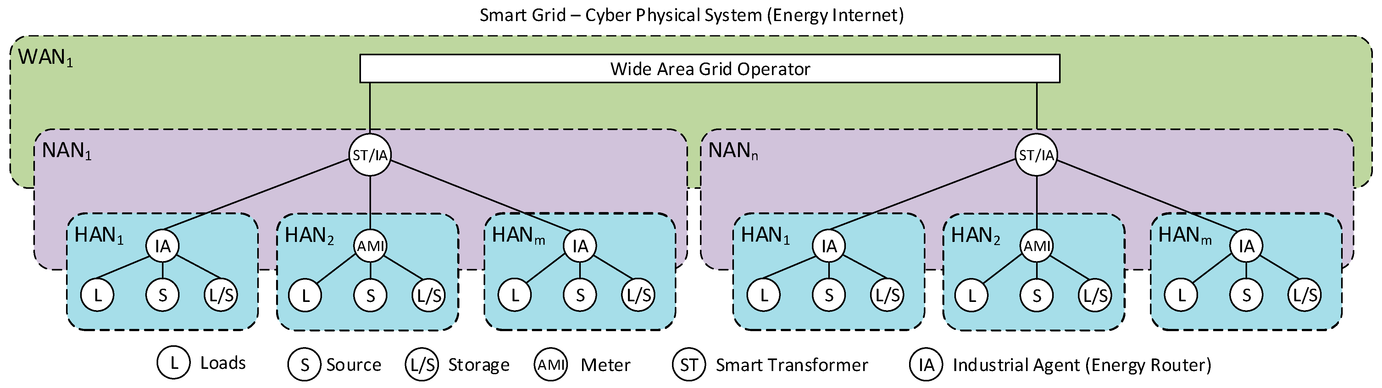
The communication between devices and users, energy suppliers, operators, management centers, and IA has become a crucial part of the modern power system providing locally balanced and self-managed local smart grids [3,16,38,39,40]. In comparison to the Internet, where routers, being the access points, manage data exchange, a similar concept can be applied to the power system. CPS would then be split based on the small local areas managed by IAs, working as “energy routers”. Therefore, it is possible to divide the power grid into areas, as presented in Figure 1, with the following hierarchical structure [40,41,42,43].
HAN—it covers the area of an intelligent building, which could be a home or business/public building managing mainly electronic devices for temperature maintenance, air conditioning, life comfort solutions, and lighting—a local network of IoT. Currently, device manufacturers already offer their non-unified platforms for managing smart home systems and intelligent buildings. However, integrating those platforms into one centrally managed system is still difficult. Additionally, the increasing number of renewable microgeneration devices and small energy storage devices, including electrical vehicle charging stations, all based on power electronics, changes the character and features of the loads in homes or business buildings. In that case, the lack of a unified approach to communication limits smart devices to their essential functions: power generation or consumption, monitoring, and scheduling. The HAN is the biggest challenge for system integration to CPS because it is the responsibility of the users and prosumers to participate in the smart energy management process and the producers to provide a unified, open, easy-to-use information exchange process.
NAN—integrates many HANs using the communication between the central IA of NAN and local IAs or advanced metering interfaces (AMIs) in the integrated HANs. Data collected from smart meters installed in HANs help determine the appropriate tariff and forecast energy demand. Moreover, combining many HANs in a NAN provides additional features like energy exchange between HANs, demand-side control, energy saving, and grid support in case of higher energy demand. A promising technology for the NAN grids is a smart transformer (ST), working as an IA from a communication point of view and as an energy router from an electrical point of view. Using power electronics converter technologies like ST with an advanced digital controller enables two-way controlled energy transmission with additional services based on communication with other devices in the network.
Wide Area Network (WAN) is the core of the entire power grid, managed by the authorized operators. Within it, automation systems are standardized, and their operation is critical for the whole distribution system and long-distance energy exchange. The WAN is managed and monitored centrally. However, the problem is the lack of proper communication with NAN subnets, resulting from using conventional transformers instead of advanced STs. The whole grid, including sub-grids, is monitored and managed in the WAN’s data center to obtain more efficient energy production, transmission, and utilization than in a classical centralized grid.
All the above sub-systems create a novel smart grid that works like an “energy internet”, with communication and data transmission between nodes with IA and ST. The energy is transferred from nodes with surplus energy to nodes with energy shortages, relieving the central source based on fossil fuels, shifting energy generation to renewable distributed sources.
Summing up the area division of smart networks, communication is well-known because of the appropriate wired or wireless interfaces and protocols that can be selected for each case from many available options [40]. Modeling the network and creating a suitable information model, which, after mapping to the selected communication interface, will facilitate the integration of intelligent devices into a coordinated, intelligent network, IoT is a much more significant challenge and must be continuously developed. It requires a standardized approach to modeling grid devices, loads, sources, and IA that will enable the successful implementation of smart grid technologies from a communication and information exchange point of view.
2.2. Unified Model of Smart Grid Devices
The concept of physical processes and device virtualization is dynamically developed due to the development of IoT technology. The communication protocols used in modern smart devices transport small data packets since the process is reduced to a small, fixed, standardized set of variables [25,44,45]. However, the number of IoT devices is constantly growing, generating vast amounts of data collected in the smart grid that must be stored and processed. The complexity additionally increases if devices do not have a standardized and minimized information model. Adopting one unified information model enables logging subsequent values in the database and adding new devices to the system without a complex setup process. The proposed models described in the literature are mainly limited to conceptual studies and apply the IEC61850 standard, which presents defined classes and namespaces related to the basic parameters of current and voltage waveforms [23,46]. Due to the need for a standardized definition of the set variables in the information model of the grid-connected device, it is challenging to configure the device during the energy management process. In addition, different data collection methods require individually tailored databases and additional data processing to include the whole system data in the aggregate database used by microgrid management algorithms.
Devices connected to the power grid have several standard features resulting from the grid parameters, such as voltage, frequency, number of phases, and direction of energy transmission (receiving or supplying). Based on those parameters, it is possible to specify unified variables to create a general information model applied to all smart devices connected to the network, creating the “Energy Internet”.
A multidimensional approach should be considered in the analyzed power grid structure, as shown in Figure 1. Categorizing network parameters and network devices, a necessary set of variables that cannot be ignored in monitoring and energy management of a smart grid must be selected.
First, the nature of the power grid itself must be considered. The primary implementation of a local microgrid is a low-voltage (LV) network with commonly used devices, which are supplied by a one- or three-phase connection to the grid. Therefore, the LV grids are characterized by a four-wire, three-phase topology with voltage parameters 230 V RMS (line-neutral) and 50 Hz based on EU standards. Considering these parameters, different connection types of the devices can be distinguished, as shown in Table 1.
Another crucial parameter of the grid devices is the power that the device consumes or supplies to the grid. Depending on the connection type (Table 1), the device can be characterized by one, two, or three different power values (for each phase separately). The power can take positive and negative values depending on the direction of the energy flow, working with varying power values from hundreds of Watts to dozens or hundreds of kW.
Modern grid devices have different roles, including passive, active, and reactive power loads. Considering the controlled power electronics devices, the direction of energy transmission between the grid and the device, and the control and communication infrastructure, the following roles of the load can be listed:
- receiver—a device capable of only consuming the energy, characterized by active and reactive power—could be a passive, non-controllable, or active electronic load.
- source—a device capable of only generating the energy, characterized by active and reactive power, integrated by a power electronics device designed to the specification of the source.
- energy storage—a device capable of storing energy and transferring it in both directions, characterized by active and reactive power, managed by the power electronics converter.
- reactive power compensator—a device intended to improve the quality of the energy, characterized mainly by reactive power; could be a passive RLC circuit or active power electronics compensator.
- measurement/control device—a piece of monitoring and controlling equipment for devices directly connected in a small area (HAN).
- control/communication router—a device dedicated to data collection and energy management in a dedicated cluster (HAN and NAN).
The energy in a smart grid can be efficiently managed by controlling the sources and energy storage and establishing a demand-side response via load management [47,48,49,50]. Therefore, additional information about the device type and purpose is needed to prioritize the loads. In critical cases (e.g., power shortage in the grid, overload in demand peak over a day, energy overproduction in renewable energy sources), all devices in the smart grid can be controlled by their category, and depending on needs, firstly, low-priority loads can be rescheduled or disconnected from the grid. Therefore, the following list should be taken into consideration as a device destination based on priority and successively increased and improved in a future unified device model:
- low-priority:
- decorative lighting (indoor and outdoor);
- washing machines;
- entertainment devices;
- advertising screens;
- cleaning devices (e.g., vacuums);
- medium-priority:
- room and building main lighting;
- heating and cooling (incl. fridges);
- road and city lighting;
- food processing (e.g., electric ovens);
- work computers;
- high-priority:
- traffic lighting;
- protection and safety devices;
- strategic devices and servers (e.g., military, bank, stock exchange);
- life support devices (e.g., respirators, surgery equipment, health monitors).
The categorization of receivers is debatable and can be standardized depending on the region and needs. Still, it is worth having the IA aware of the critical role of the high-priority receivers. In the case of an energy shortage, when the management principle assumes that there is a threat to life or valuable property, the energy should be supplied as long as possible. On the other hand, devices used for entertainment and increasing the standard of living can be disconnected first. The method of switching on and operating time of the devices may also be considered for listed groups. Low-priority loads are characterized by the possibility of long disconnection from the grid, while medium-priority devices can be disconnected for a few hours to keep the power balance. The user should be able to start the device on demand (e.g., in a medium-priority group), or it can be started at different hours of the day.
Returning to a group of devices with a specific role in the grid, in which energy is managed and not consumed (sources and storage), it should be noted that electric cars and batteries, which can be receivers, provide an opportunity to store energy as well as exchange it with the grid (Vehicle-to-Grid, V2G). In addition, the amount of charging energy is relatively large compared to the rest of the household receivers. Considering the possibility of storing energy and integrating the power in time, receivers and storage can provide information about the stored or required energy resources. Considering the power demand in each period, how the device turns on, and how long it is used should also be considered. The possible circumstances are characterized in Table 2.
Based on the device power demand information, the efficient energy management strategy can predict the power demand during the day and control all IA and grid devices to provide local grid stability and minimize the cost based on the energy tariff [51,52].
Besides the described parameters of the smart grid load device, the critical aspect is its status and ability to read the commands sent from the IA. The status of an electrical device includes options: idle, ready, operational, and fault, which the IA can read, and commands: connect, disconnect, start, stop, and reset, read by the device.
Moreover, the power electronics converters with their own control, communication, and measurement units can send information about instantaneous powers, current’s total harmonic distortion factors (THD), root mean square values (RMS), or average values of voltages and currents, energy storage capacity, and state of charge (SOC) to the IA or energy management center. Therefore, the additional structure of the advanced electrical parameter monitoring can be included in the load model, helping to improve energy management.
2.3. Development and Implementation of the Unified Data Model of the Smart Grid Loads—Devices
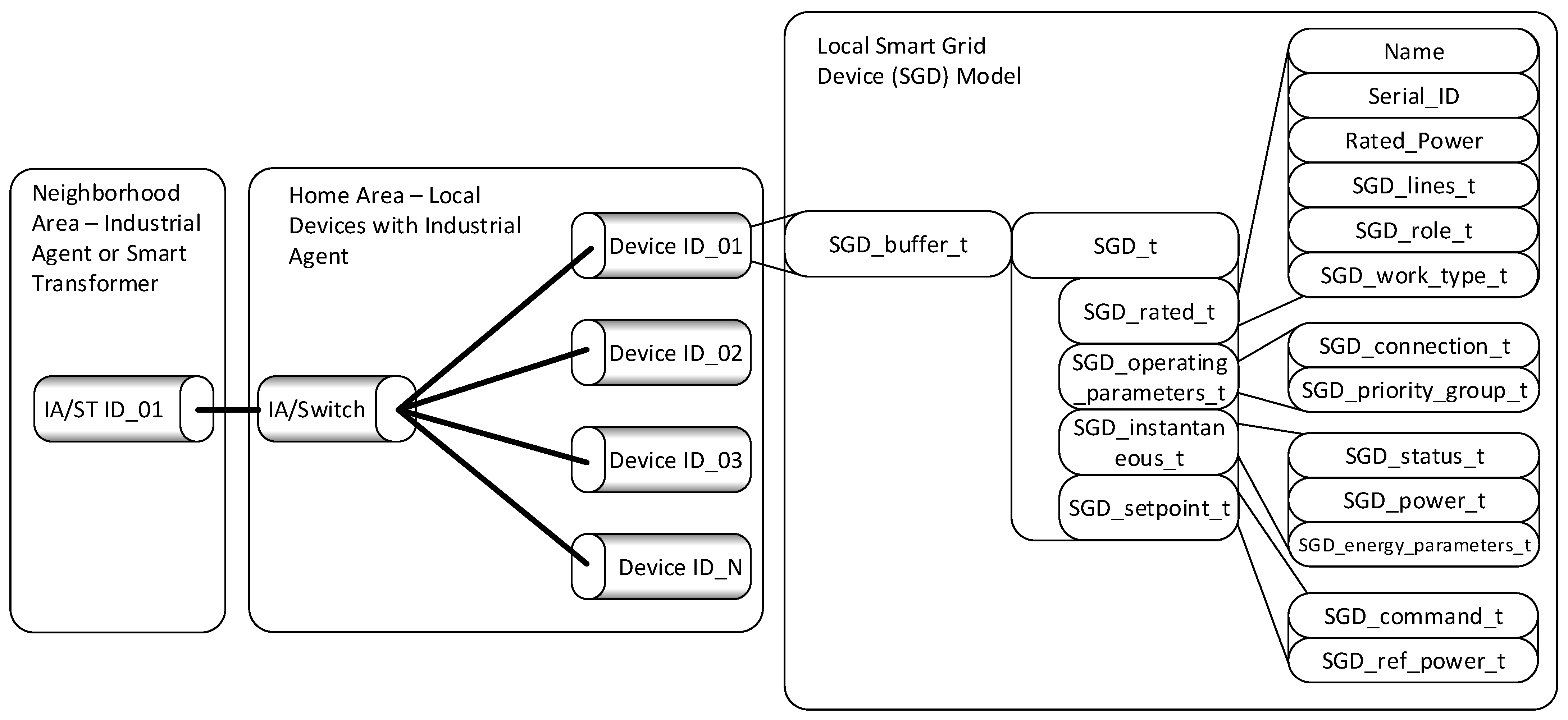
Considering many different devices integrated into one modern smart grid, implementing the unified device model will require changes to many manufacturers’ software based on the one proposed unified standard. The device model has been implemented in C++, and its data are stored in a structure called SGD_buffer_t in the device memory (Figure 2). Inside this element, the reference to the device parameters is included by implementing a structure SGD_t with all groups of parameters, like rated values, operating parameters set to start the device work, measured and stored instantaneous values, the setpoint for the device control, and energy management.
The first group of parameters written as a structure SGD_rated_t represents basic information characterizing the device, listed in Table 3. It allows reading the device’s name, unique serial ID number, and rated power. Moreover, it provides information about the number of used grid lines defined in an enumeration data type (Table 3). Next, the defined role of the device in the smart grid or smart home is included. The final structure inside the SGD_rated_t defines the work type of the device, providing the information that can be used in an advanced energy management algorithm for the smart grid. The work types are shown in Table 3.
The second group of device parameters has been proposed in the structure SGD_operating_parameters_t. In this group, information about actual operating parameters is provided, like connected specified grid lines or set priority of the device. Depending on needs or customer preferences, they can be changed at the beginning of the device’s operation. The first parameter in this group is based on the enum list defining all possible connections of one- and three-phase devices.
The selected device priority, implemented as an enum list, provides important information to the IA, especially from the energy management standpoint.
The third group of device information is related to the instantaneous values of the crucial electrical parameters and operation status, which can be changed in each communication cycle. Parameters like information about actual powers (based on the list in Table 3) or energy quality can improve the grid’s voltages and currents and provide a self-balanced area or zero-emission building. Each device may get a fault, stop operation, or change its operation mode; therefore, the device status update is sent to the IA as an instantaneous value based on the defined list in the proposed unified model.
The last group of device parameters has been included in the structure SGD_setpoint_t. Inside this group are parameters received from IA or AMI (which manage the local grid) and read by the device to participate in the power management process. First, control commands have been defined in the enum list. Secondly, the referenced values of powers are set by sending the values from IA to the device, which are calculated in the power management algorithm implemented for the whole considered area or building.
Summarizing the proposed unified device model, it is possible to split all exchange information for:
- parameters—constant during device operation, exchanged at the start:
- SGD_rated_t;
- SGD_operation_parameters_t;
- outputs—values sent from the device to the IA or AMI:
- SGD_instantanous_t;
- inputs—values sent from IA or AMI to the device to manage the operating parameters and provide advanced energy management:
- SGD_setpoint_t.
This classification makes the proposed model easy to implement in many different communication standards suitable for industrial networks, power systems, micro- or smart grids like EtherCAT (for distances under 100 m between devices, e.g., buildings) [53,54], Ethernet, the MQTT protocol designed for IoT systems [25], PROFINET used in industrial application, e.g., renewable energy systems [27], Modbus RTU, or TCP/IP, widely used in the communication of power electronics devices [26].
3. Results
The developed model of the loads (sources, storage, and passive components) has been implemented in the C++ language separately for each device, HAN, and NAN IAs, working as energy routers. The language has been selected based on the specific applications—all small devices connected to the local grids controlled by microcontrollers. These devices communicate with the server by sending and receiving small, fixed-size data packets. C++ implementation allows precise management of data types and bit sizes to optimize data size. This makes it possible to determine how many bits are needed to store a given piece of information or parameter, e.g., SGD_lines_t can be stored on 2 bits, SGD_role_t on 4 bits, and SGD_work_type_t on 2 bits, which together gives 8 bits and can be stored in one memory address using the bit field structure mechanism. These three pieces of information can be sent as a single byte. However, for larger devices with large memory and database, IA, Energy Routers, etc., the same unified data model can be implemented using, e.g., Python or C#.
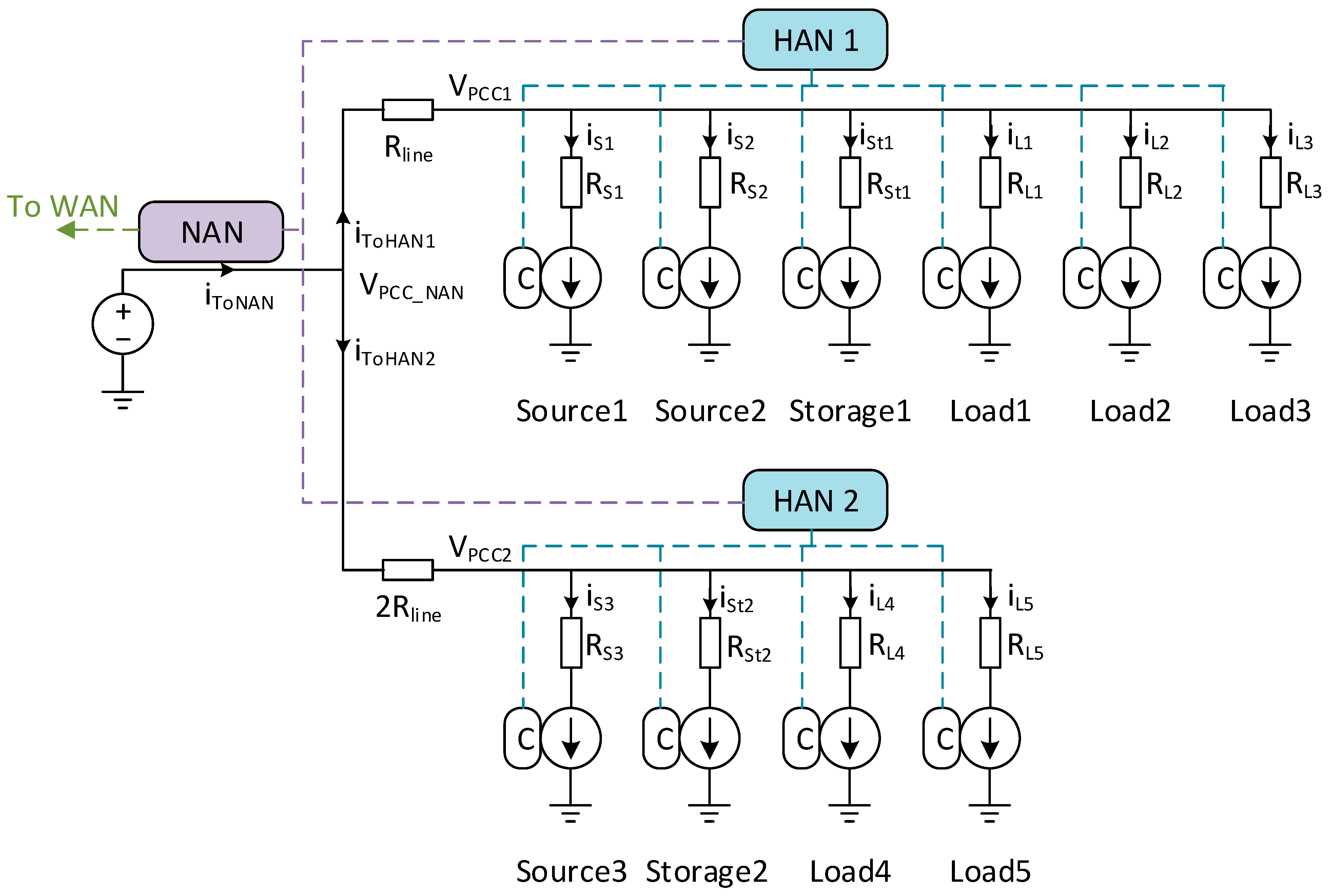
The proposed information model was verified in the simulation process, including two HANs with different devices cooperating in one NAN. The simulation model is presented in Figure 3.
The distances between each device/load and HANs have been simulated by resistances relative to the lengths of electrical cables used in the local grid. The selected resistances are shown in Table 4. The different values of the resistances influence the voltage drop in each point of common coupling (PCC) managed by the HAN’s IA. As a microgrid control strategy, the self-balanced process for each HAN was simulated based on the examples of loads’ and renewable energy sources’ profiles. In each self-balanced area, the energy storage was simulated, charged only from local sources to decrease the power delivered from the main source (from WAN).
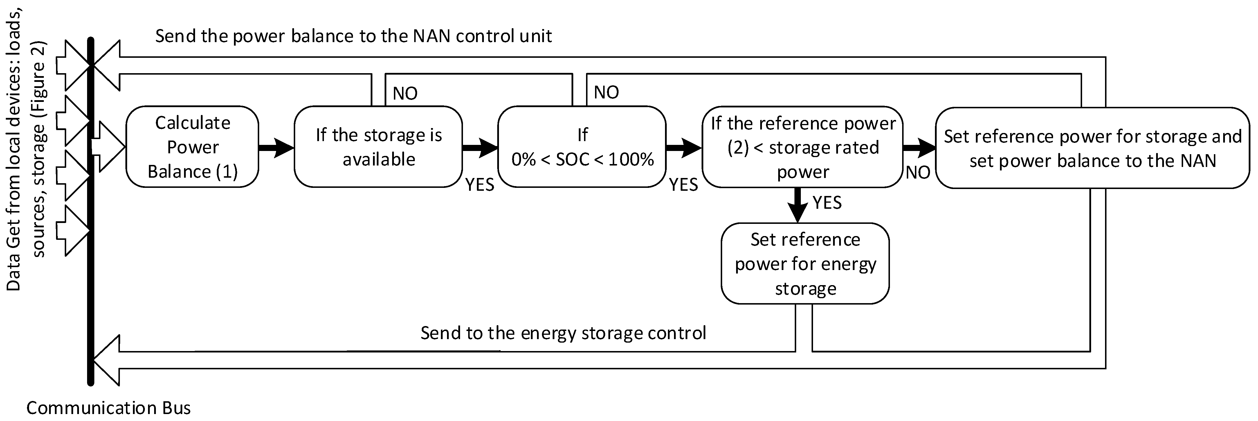
The unified information model of each connected device is sent in both directions between the HAN and devices, as well as HANs and NAN IA. The studied power management method utilizing the proposed unified device model is shown in Figure 4. In the first step of the implemented control strategy, each HAN control unit collects the values of the actual active powers of the controlled N number of devices (included in SGD_power_t—Table 3). Then, the total power in the local HAN is derived:
Depending on the current direction, the power can be negative (related to the source or storage—energy is delivered to the grid/loads) or positive (energy is consumed or accumulated in the storage). Then, based on the device role, the algorithm can check if the storage is available to balance the power in the local area (based on SGD_role_t). If there is no storage, the power balance Ptotal is sent to the NAN controller as a total_active power of the HAN (SGD_power_t); otherwise, if there is storage with operating or ready mode (SGD_status_t), the algorithm checks the information about actual SOC.
As long as the storage is not fully charged or discharged, the control unit calculates the reference power Pstorage_ref to provide the self-balanced operation:
Providing complete information about the device, the HAN control unit can check in the next step if the calculated reference value is within the limit of the device’s rated power (SGD_rated_t). In case of higher power demand than the rated power of the storage or if the SOC is in the limit, the information about the power balance in the HAN (1) is sent to the NAN to provide the balance from the nearest HANs or WAN.
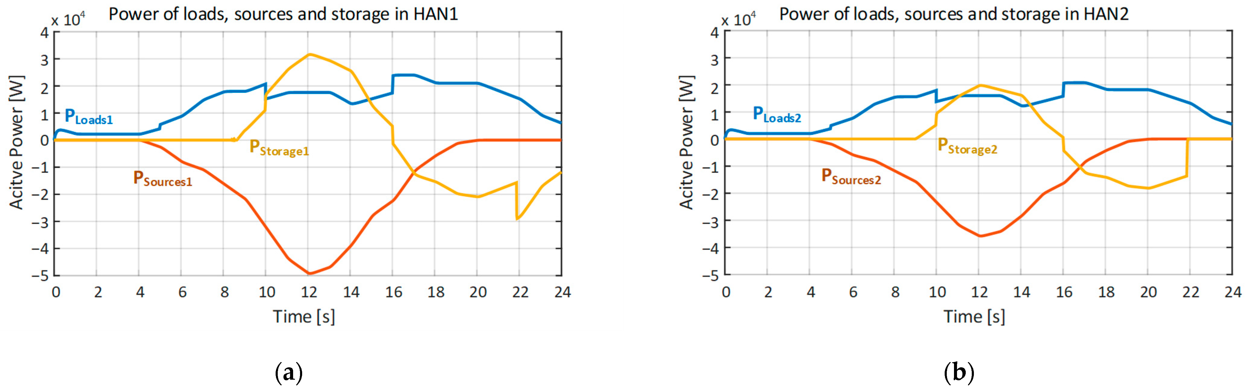
From an electrical point of view, each device, load, storage, and source was simulated as a controlled current source based on the proposed unified information model. The simulation process was performed in a 24 s window, considering dynamic loads and source power changes like the typical day characteristics. The local sources could produce the energy only between 4 and 19 s of simulation (e.g., PV panels during summer days). The energy storage was considered fully discharged initially and charged only from local sources. The waveforms of the loads, sources, and storage powers obtained during the analyzed case are shown in Figure 5. All electrical parameters were transmitted with the delay of one sample time—277.8 µs. As described in the previous section, the transmitted data were grouped separately as parameters, outputs, and input signals for each device.
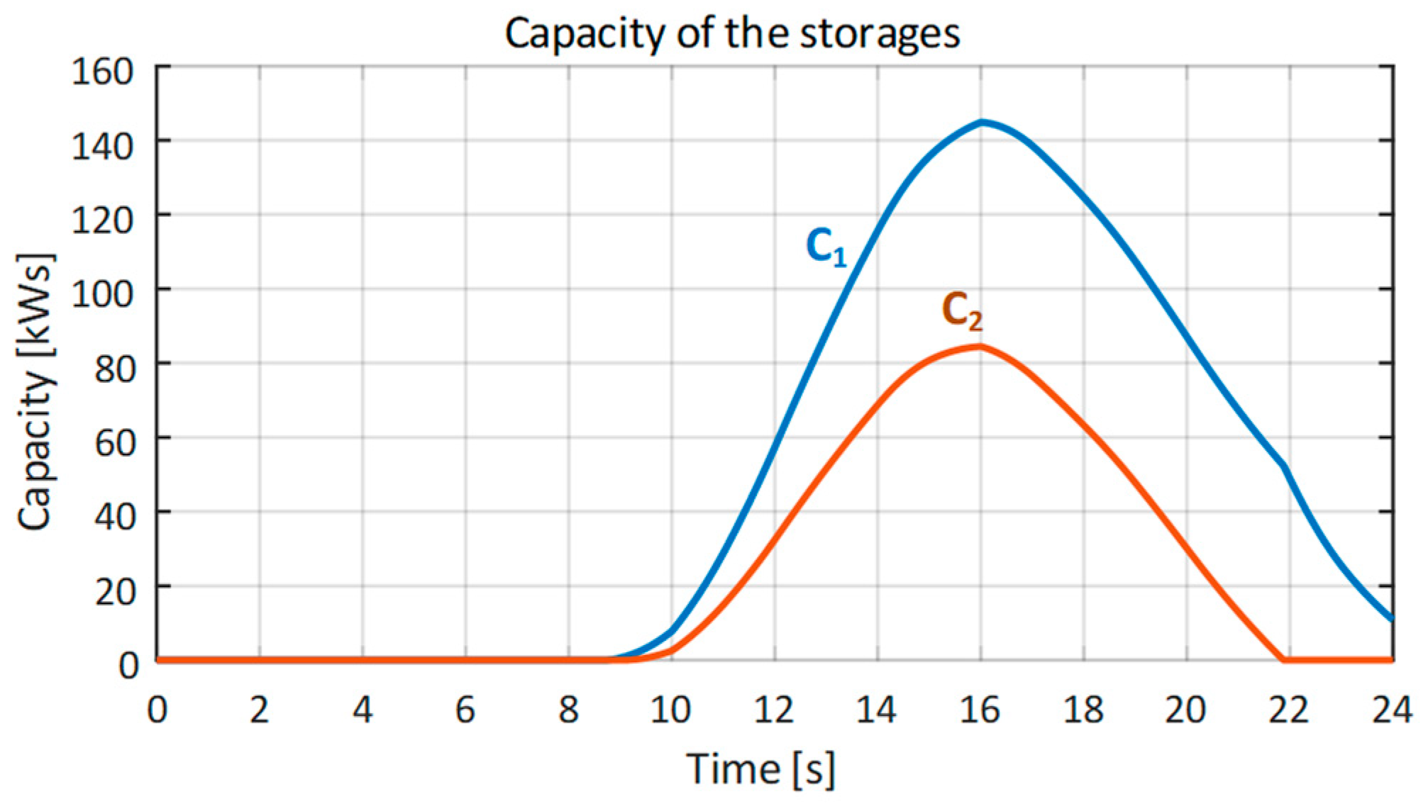
The process of charging energy storage starts at 9 when the balance of local loads’ powers and local sources’ powers calculated in the HAN’s IA Ptotal is negative (1). For each HAN, the different energy storage capacities were considered; therefore, at the peak of the power, the capacities reach a different level, as shown in Figure 6.
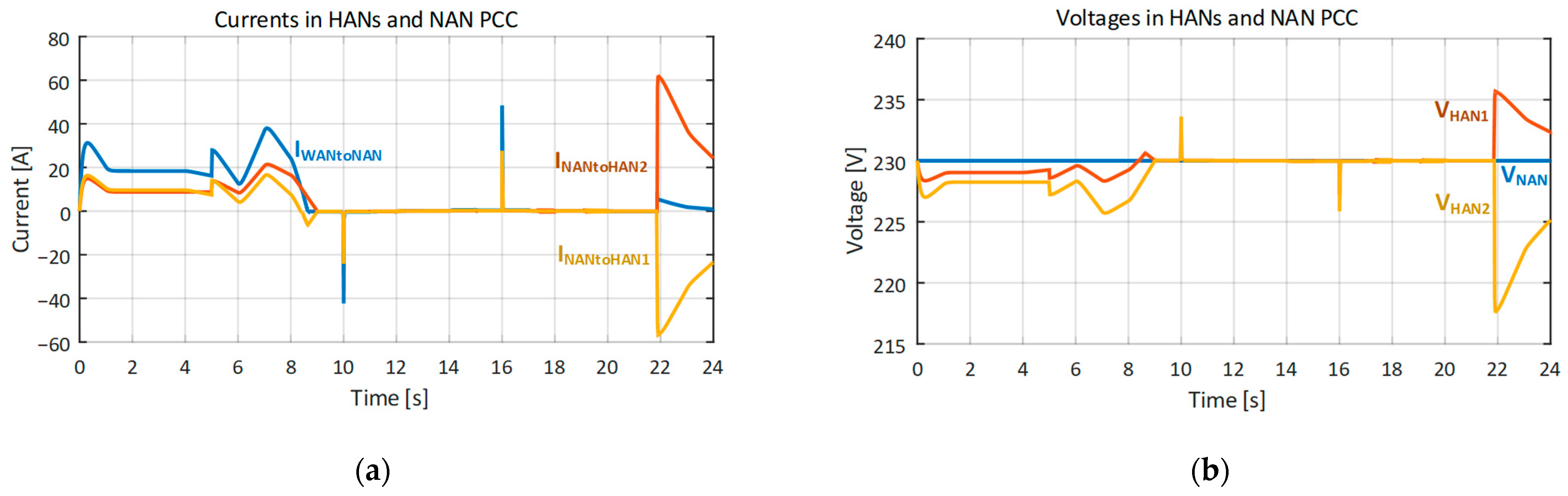
In the first 9 s, the power system works without energy accumulated in the storage. Therefore, there is no possibility of balancing the power in local HANs. The energy must be transmitted from WAN through transmission lines and the distribution grid, causing the voltage drop for the farthest point of the system (HAN PCC). It is shown in Figure 7b. The voltage can drop significantly depending on the internal line resistance (in the cable lines of the distribution grid). This situation corresponds to the standard grid operation without advanced power management algorithms or the proposed unified load information model.
After 9 s, the power balance in HANs allows for energy accumulation in the local storage and self-balancing separately in each local area. This situation can be observed in the current waveforms measured between HANs and NAN PCCs, shown in Figure 7a. No current is transmitted from the WAN or NAN part of the grid to the local areas. As a result, the local power balance improves the level of the local voltages in PCCs (Figure 7b), restoring the nominal RMS values of the measured voltages. During the condition changes, e.g., sudden load disconnection, the delay in the communication process causes the current and voltage impulses—dynamic states of the self-balancing process. Depending on the used communication interface and the distance between local devices and IA or energy routers, they can take a few seconds to minutes in the actual smart grid.
Considering self-balanced areas (HANs) as a case study for implementing a developed unified load information model and energy management based on the exchange data, the power balance in the whole grid must be kept all the time. When the local microgrid—HAN—cannot provide the power balance for its loads, the HAN control unit sends a load information model to the NAN and provides information about the lack of power. Then, in 22 s, the NAN controller manages the energy exchange between the nearest HANs instead of WAN and the faraway generators. After the dynamic state, no current is transmitted from WAN (Figure 7a), and the currents between NAN and HANs appear.
4. Discussion
The proposed unified data profile for the load, source, storage, IA, or Energy Router has been implemented in the C++ language in the simulation model of the microgrid, consisting of two local HANs and NAN. However, the defined code structure allows using any other language, like C or Python. The proposed solution models control and communication, including parameter-based profiles, input, and output data. Based on advanced communication with the pre-defined model of devices, including energy routers in HAN and NAN grids, this allows the development of many different power management strategies depending on the needs or grid codes. From the most common approach, the following can be considered:
- Self-balanced local grids in HANs—tested with the described solution;
- Dynamic energy tariffs and energy transmission based on the economic profits for customers;
- Reduction in energy transmission in MV grids usually used between WAN and NAN grids;
- Lack of energy compensated from the closest HANs to limit the current in the distributed NAN grids—tested with the described solution;
- Energy management in the grid is based on artificial intelligence, machine learning, or optimization processes.
The same developed unified data profile for the loads and devices in the grid can be a source for the management algorithms.
In a future study, more strategies will be considered in developing an energy management algorithm based on the designed unified device profile. The research will focus on a comprehensive simulation analysis of developed algorithms and experimental verification of the developed dedicated laboratory station, including communication technologies like Ethernet, EtherCAT, PROFINET, Modbus TCP/IP, etc.
5. Conclusions
Without a unified device model, management of electrical energy systems in areas wider than one HAN, building, or residential sub-system and with many modern devices connected to the local grids is difficult and time-consuming. The unified data model split for strictly specific groups, parameters, inputs, and outputs, increases the possibility of developing advanced energy management methods dedicated to distributed generation systems. It must be possible to implement in the microcontroller with limited memory. Therefore, the proposed model was implemented in a low-level programming language, namely C++. It allows precise management of data types and bit sizes so that data packets are optimized in size. This makes it possible to determine how many bits are needed to store a given piece of information or parameter, e.g., SGD_lines_t can be stored on 2 bits, SGD_role_t on 4 bits, and SGD_work_type_t on 2 bits, which together give 8 bits and can be stored in one memory address using the bit field structure mechanism. These three pieces of information can be sent as a single byte.
From the point of view of the energy or power management algorithms described in the literature, the model provides all the needed information to use advanced management methods, optimization processes, artificial intelligence, machine learning, etc. One unified model implemented in each device separately can be used with different communication infrastructure and protocols, and it does not require integrating many different communication interfaces or additional data mapping in area control units, which is needed when each device has a different data model.
Author Contributions
Conceptualization, A.M. and K.M.; methodology, A.M.; software, K.M.; validation, A.M.; formal analysis, A.M.; investigation, A.M.; resources, K.M.; data curation, K.M.; writing—original draft preparation, A.M.; writing—review and editing, A.M.; visualization, A.M.; supervision, A.M. All authors have read and agreed to the published version of the manuscript.
Funding
This research was funded by Warsaw University of Technology under Grant POB Konwersja i Magazynowanie Energii ENERGYTECH-1 “System wielopoziomowego zarządzania energią elektryczną w sieci inteligentnej Smart Grid bazujący na standaryzacji profilów urządzeń sieciowych”.
Data Availability Statement
Data are contained within the article.
Acknowledgments
The simulation analysis of the developed solution has been performed in the Division of Industrial Electronics, Institute of Control and Industrial Electronics, Faculty of Electrical Engineering at Warsaw University of Technology, using devices and software available for the conducted research.
Conflicts of Interest
The authors declare no conflicts of interest.
References
- Rahman, M.S.; Mahmud, M.A.; Oo, A.M.T.; Pota, H.R. Multi-Agent Approach for Enhancing Security of Protection Schemes in Cyber-Physical Energy Systems. IEEE Trans. Ind. Inform. 2017, 13, 436–447. [Google Scholar] [CrossRef]
- Hammad, E.; Farraj, A.; Kundur, D. On Cyber-Physical Coupling and Distributed Control in Smart Grids. IEEE Trans. Ind. Inform. 2018, 15, 4418–4429. [Google Scholar] [CrossRef]
- Kong, P.; Member, S. Between Communication Network and Power Grid. IEEE Trans. Ind. Inform. 2019, 15, 4054–4065. [Google Scholar] [CrossRef]
- Oyewole, P.A.; Jayaweera, D. Power System Security with Cyber-Physical Power System Operation. IEEE Access 2020, 8, 179970–179982. [Google Scholar] [CrossRef]
- Karnouskos, S.; Leitao, P.; Ribeiro, L.; Colombo, A.W. Industrial Agents as a Key Enabler for Realizing Industrial Cyber-Physical Systems: Multiagent Systems Entering Industry 4.0. IEEE Ind. Electron. Mag. 2020, 14, 18–32. [Google Scholar] [CrossRef]
- Yin, S.; Rodriguez-Andina, J.J.; Jiang, Y. Real-Time Monitoring and Control of Industrial Cyberphysical Systems: With Integrated Plant-Wide Monitoring and Control Framework. IEEE Ind. Electron. Mag. 2019, 13, 38–47. [Google Scholar] [CrossRef]
- Shang, C.; Bao, X.; Fu, L.; Xia, L.; Xu, X.; Xu, C. A Novel Key-Value Based Real-Time Data Management Framework for Ship Integrated Power Cyber-Physical System. In Proceedings of the 2019 IEEE PES Innovative Smart Grid Technologies Asia, ISGT 2019, Chengdu, China, 25 June 2019; pp. 854–858. [Google Scholar] [CrossRef]
- Numair, M.; Mansour, D.E.A.; Mokryani, G. A Proposed IoT Architecture for Effective Energy in Smart Microgrids. In Proceedings of the NILES2020: 2nd Novel Intelligent and Leading Emerging Sciences Conference, Giza, Egypt, 24–26 October 2020; pp. 594–599. [Google Scholar]
- Wu, Y.; Wu, Y.; Guerrero, J.M.; Vasquez, J.C.; Palacios-García, E.J.; Guan, Y. IoT-Enabled Microgrid for Intelligent Energy-Aware Buildings: A Novel Hierarchical Self-Consumption Scheme with Renewables. Electronics 2020, 9, 550. [Google Scholar] [CrossRef]
- Alhasnawi, B.N.; Jasim, B.H.; Sedhom, B.E.; Hossain, E.; Guerrero, J.M. A New Decentralized Control Strategy of Microgrids in the Internet of Energy Paradigm. Energies 2021, 14, 2183. [Google Scholar] [CrossRef]
- Routray, S.K.; Javali, A.; Gopal, D.; Sharma, L.; Sharmila, K.P.; Sahoo, A. IoT-Based Microgrids for Rural Electrification. In Proceedings of the 5th International Conference on I-SMAC (IoT in Social, Mobile, Analytics and Cloud), I-SMAC 2021, Palladam, India, 11–13 November 2021; Institute of Electrical and Electronics Engineers Inc.: Piscataway, NJ, USA, 2021; pp. 275–279. [Google Scholar]
- Voumick, D.; Deb, P.; Khan, M.M. Operation and Control of Microgrids Using IoT (Internet of Things). J. Softw. Eng. Appl. 2021, 14, 418–441. [Google Scholar] [CrossRef]
- Khoa, N.M.; van Dai, L.; Tung, D.D.; Toan, N.A. An Advanced IoT System for Monitoring and Analysing Chosen Power Quality Parameters in Micro-Grid Solution. Arch. Electr. Eng. 2021, 70, 173–188. [Google Scholar] [CrossRef]
- Aljafari, B.; Vasantharaj, S.; Indragandhi, V.; Vaibhav, R. Optimization of DC, AC, and Hybrid AC/DC Microgrid-Based IoT Systems: A Review. Energies 2022, 15, 6813. [Google Scholar] [CrossRef]
- Reddy, G.P.; Kumar, Y.V.P.; Chakravarthi, M.K. Communication Technologies for Interoperable Smart Microgrids in Urban Energy Community: A Broad Review of the State of the Art, Challenges, and Research Perspectives. Sensors 2022, 22, 5881. [Google Scholar] [CrossRef]
- Leitão, P.; Karnouskos, S.; Ribeiro, L.; Lee, J.; Strasser, T.; Colombo, A.W. Smart Agents in Industrial Cyber-Physical Systems. Proc. IEEE 2016, 104, 1086–1101. [Google Scholar] [CrossRef]
- Dai, W.; Nishi, H.; Vyatkin, V.; Huang, V.; Shi, Y.; Guan, X. Industrial Edge Computing: Enabling Embedded Intelligence. IEEE Ind. Electron. Mag. 2019, 13, 48–56. [Google Scholar] [CrossRef]
- Silva, D.D.E.; Sierla, S.; Alahakoon, D.; Osipov, E.; Yu, X.; Vyatkin, V. Toward Intelligent Industrial Informatics. IEEE Ind. Electron. Mag. 2020, 14, 57–72. [Google Scholar] [CrossRef]
- Leitao, P.; Karnouskos, S.; Ribeiro, L.; Moutis, P.; Barbosa, J.; Strasser, T.I. Common Practices for Integrating Industrial Agents and Low Level Automation Functions. In Proceedings of the IECON 2017—43rd Annual Conference of the IEEE Industrial Electronics Society, Beijing, China, 29 October–1 November 2017; pp. 6665–6670. [Google Scholar] [CrossRef]
- Buccella, C.; Cecati, C.; Abu-Rub, H. An Overview on Distributed Generation and Smart Grid Concepts and Technologies. In Power Electronics for Renewable Energy Systems, Transportation and Industrial Applications; Wiley: Hoboken, NJ, USA, 2014; Volume 9781118634, pp. 50–68. ISBN 9781118755525. [Google Scholar]
- Andrén, F.; Bründlinger, R.; Strasser, T. IEC 61850/61499 Control of Distributed Energy Resources: Concept, Guidelines, and Implementation. IEEE Trans. Energy Convers. 2014, 29, 1008–1017. [Google Scholar] [CrossRef]
- IEC 61850-7-2; Standard for Communication Networks and Systems in Substations. International Electrotechnical Commission: Geneva, Switzerland, 2003.
- Aftab, M.A.; Hussain, S.S.; Ali, I.; Ustun, T.S. IEC 61850-Based Communication Layer Modeling for Electric Vehicles. IEEE Ind. Electron. Mag. 2020, 14, 4–14. [Google Scholar] [CrossRef]
- Strasser, T.; Andren, F.; Vyatkin, V.; Zhabelova, G.; Yang, C.W. Towards an IEC 61499 Compliance Profile for Smart Grids Review and Analysis of Possibilities. In Proceedings of the IECON 2012—38th Annual Conference on IEEE Industrial Electronics Society, Montreal, QC, Canada, 25–28 October 2012; pp. 3750–3757. [Google Scholar] [CrossRef]
- Jun, H.J.; Yang, H.S. Performance of the XMPP and the MQTT Protocols on IEC 61850-Based Micro Grid Communication Architecture. Energies 2021, 14, 5024. [Google Scholar] [CrossRef]
- González, I.; Calderón, A.J.; Folgado, F.J. IoT Real Time System for Monitoring Lithium-Ion Battery Long-Term Operation in Microgrids. J. Energy Storage 2022, 51, 104596. [Google Scholar] [CrossRef]
- Polimeni, S.; Nespoli, A.; Leva, S.; Valenti, G.; Manzolini, G. Implementation of Different Pv Forecast Approaches in a Multigood Microgrid: Modeling and Experimental Results. Processes 2021, 9, 323. [Google Scholar] [CrossRef]
- Abbasi, M.; Abbasi, E.; Li, L.; Aguilera, R.P.; Lu, D.; Wang, F. Review on the Microgrid Concept, Structures, Components, Communication Systems, and Control Methods. Energies 2023, 16, 484. [Google Scholar] [CrossRef]
- Jangid, B.; Mathruria, P.; Gupta, V. Load Profile Segmentation of Various Load Categories Using Clustering. In Proceedings of the 2021 IEEE 2nd International Conference on Electrical Power and Energy Systems, ICEPES 2021, Bhopal, India, 10–11 December 2021; Institute of Electrical and Electronics Engineers Inc.: Piscataway, NJ, USA, 2021. [Google Scholar]
- Alam, M.M.; Shahjalal, M.; Islam, M.M.; Hasan, M.K.; Ahmed, M.F.; Jang, Y.M. Power Flow Management with Demand Response Profiles Based on User-Defined Area, Load, and Phase Classification. IEEE Access 2020, 8, 218813–218827. [Google Scholar] [CrossRef]
- Loggia, R.; Flamini, A.; Massaccesi, A.; Moscatiello, C.; Galasso, A.; Martirano, L. Electrical Load Profiles for Residential Buildings: Enhanced Bottom-Up Model (EBM). In Proceedings of the 2023 International Conference on Clean Electrical Power, ICCEP 2023, London, UK, 21–22 October 2023; Institute of Electrical and Electronics Engineers Inc.: Piscataway, NJ, USA, 2023; pp. 635–640. [Google Scholar]
- Omitaomu, O.A.; Niu, H. Artificial Intelligence Techniques in Smart Grid: A Survey. Smart Cities 2021, 4, 548–568. [Google Scholar] [CrossRef]
- Ozcanli, A.K.; Yaprakdal, F.; Baysal, M. Deep Learning Methods and Applications for Electrical Power Systems: A Comprehensive Review. Int. J. Energy Res. 2020, 44, 7136–7157. [Google Scholar] [CrossRef]
- Bose, B.K. Artificial Intelligence Techniques: How Can It Solve Problems in Power Electronics?: An Advancing Frontier. IEEE Power Electron. Mag. 2020, 7, 19–27. [Google Scholar] [CrossRef]
- Żołądek, M.; Figaj, R.; Kafetzis, A.; Panopoulos, K. Energy-Economic Assessment of Self-Sufficient Microgrid Based on Wind Turbine, Photovoltaic Field, Wood Gasifier, Battery, and Hydrogen Energy Storage. Int. J. Hydrogen Energy 2024, 52, 728–744. [Google Scholar] [CrossRef]
- Sicchar, J.; Da Costa, C.; Silva, J.; Oliveira, R.; Oliveira, W. A Load-Balance System Design of Microgrid Cluster Based on Hierarchical Petri Nets. Energies 2018, 11, 3245. [Google Scholar] [CrossRef]
- Martínez-Caballero, L.; Kot, R.; Milczarek, A.; Malinowski, M. Comparison of Energy Storage Management Techniques for a Grid-Connected PV- and Battery-Supplied Residential System. Electronics 2023, 13, 87. [Google Scholar] [CrossRef]
- Baimel, D.; Tapuchi, S.; Baimel, N. Smart Grid Communication Technologies. J. Power Energy Eng. 2016, 4, 1–8. [Google Scholar] [CrossRef]
- Vu, T.V.; Nguyen, B.L.H.; Cheng, Z.; Chow, M.-Y.; Zhang, B. Cyber-Physical Microgrids. IEEE Ind. Electron. Mag. 2020, 14, 4–17. [Google Scholar] [CrossRef]
- Kuzlu, M.; Pipattanasomporn, M.; Rahman, S. Communication Network Requirements for Major Smart Grid Applications in HAN, NAN and WAN. Comput. Netw. 2014, 67, 74–88. [Google Scholar] [CrossRef]
- Zhang, Y.; Wang, L.; Sun, W.; Green, R.C.; Alam, M. Distributed Intrusion Detection System in a Multi-Layer Network Architecture of Smart Grids. IEEE Trans. Smart Grid. 2011, 2, 796–808. [Google Scholar] [CrossRef]
- Ding, Y.; Tian, Y.C.; Li, X.; Mishra, Y.; Ledwich, G.; Zhou, C. Constrained Broadcast with Minimized Latency in Neighborhood Area Networks of Smart Grid. IEEE Trans. Ind. Inform. 2020, 16, 309–318. [Google Scholar] [CrossRef]
- Jayashree, L.; Sandanalakshmi, R. Priority Based Routing Framework for Neighborhood Area Network in Smart Grid Communication. In Proceedings of the 2017 International Conference on Wireless Communications, Signal Processing and Networking, WiSPNET 2017, Chennai, India, 22–24 March 2017; pp. 1483–1487. [Google Scholar] [CrossRef]
- Bedi, G.; Venayagamoorthy, G.K.; Singh, R.; Brooks, R.R.; Wang, K.-C. Review of Internet of Things (IoT) in Electric Power and Energy Systems. IEEE Internet Things J. 2018, 5, 847–870. [Google Scholar] [CrossRef]
- Koch, D.B. An Internet of Things Approach to Electrical Power Monitoring and Outage Reporting. In Proceedings of the Conference Proceedings—IEEE SOUTHEASTCON 2017, Concord, NC, USA, 30 March–2 April 2017; pp. 37–39. [Google Scholar] [CrossRef]
- Rzepecki, A. Modelowanie Systemu Elektroenergetycznego Z Użyciem Standardu Cim Iec61970. Inform. Control Meas. Econ. Environ. Prot. 2015, 5, 47–50. [Google Scholar] [CrossRef]
- Feng, Y.; Liu, Y.; Zeng, X.; Gao, L. Power Demand Side Response Potential and Operating Model Based on EV Mobile Energy Storage. In Proceedings of the 2017 IEEE Conference on Energy Internet and Energy System Integration, EI2 2017—Proceedings 2017, Beijing, China, 27–28 November 2017; pp. 1–6. [Google Scholar] [CrossRef]
- Wang, H.Z.C.G.W.J.G.P.W. Optimization Dispatch Modeling for Demand Response Considering Supply and Demand Balance and Security Constraints. In Proceedings of the 2021 Power System and Green Energy Conference (PSGEC), Shanghai, China, 20–22 August 2021; IEEE: New York, NY, USA, 2021; pp. 166–170. [Google Scholar]
- Xu, F.Y.; Lai, L.L. Novel Active Time-Based Demand Response for Industrial Consumers in Smart Grid. IEEE Trans. Ind. Inform. 2015, 11, 1564–1573. [Google Scholar] [CrossRef]
- Palensky, P.; Dietrich, D. Demand Side Management: Demand Response, Intelligent Energy Systems, and Smart Loads. IEEE Trans. Ind. Inform. 2011, 7, 381–388. [Google Scholar] [CrossRef]
- Tayyab, M.; Hauer, I.; Klabunde, C.; Wolter, M. Optimal Hybrid Storage Planning under Different Tariffs in a Microgrid. In Proceedings of the IEEE PES Innovative Smart Grid Technologies Conference Europe, Delft, The Netherlands, 26–28 October 2020; pp. 61–65. [Google Scholar] [CrossRef]
- Skytte, K.; Bergaentzle, C.; Soysal, E.R.; Olsen, O.J. Design of Grid Tariffs in Electricity Systems with Variable Renewable Energy and Power to Heat. In Proceedings of the International Conference on the European Energy Market, EEM 2017, Dresden, Germany, 6–9 June 2017. [Google Scholar] [CrossRef]
- Kim, D.; Lee, J.; Lee, S.-H.; Kim, S. High-Bandwidth Control Structure for Solid-State-Transformers with EtherCAT Protocol. In Proceedings of the 2023 11th International Conference on Power Electronics and ECCE Asia (ICPE 2023—ECCE Asia), Jeju, Republic of Korea, 22–25 May 2023; IEEE: New York, NY, USA, 2023; pp. 1843–1848. [Google Scholar]
- Schmelter, A.; Ortjohann, E.; Holtschulte, D.; Premgamone, T.; Andreas, J.; Loanka, S.; Kortenbruck, J.; Morton, D. Cluster Data Communication for Decentralized Grid Operation Based on Clustering Power System Approach. In Proceedings of the 2023 International Conference on Clean Electrical Power (ICCEP), London, UK, 27 June 2023; IEEE: New York, NY, USA, 2023; pp. 916–923. [Google Scholar]
Figure 1.
The block scheme of a smart grid as a CPS—Energy Internet split to HAN, NAN, and WAN zones.
Figure 1.
The block scheme of a smart grid as a CPS—Energy Internet split to HAN, NAN, and WAN zones.

Figure 2.
The block diagram of the unified smart grid device model used in the HAN.

Figure 3.
The block scheme of simulated microgrid with two HANs in one NAN.

Figure 4.
The flowchart of the selected power management method (locally balanced power) was implemented in the HAN control unit.
Figure 4.
The flowchart of the selected power management method (locally balanced power) was implemented in the HAN control unit.

Figure 5.
Active powers of the loads, sources, and storage during the analyzed time window: (a) power waveforms for HAN 1; (b) power waveforms for HAN 2.
Figure 5.
Active powers of the loads, sources, and storage during the analyzed time window: (a) power waveforms for HAN 1; (b) power waveforms for HAN 2.

Figure 6.
The energy capacity of the storage in each HAN during the analyzed time window.

Figure 7.
Currents between each grid area (WAN to NAN, NAN to HAN 1, NAN to HAN 2) and voltages in PCCs: (a) currents between HANs and NAN, and current from WAN to NAN; (b) voltages in HANs and NAN PCCs.
Figure 7.
Currents between each grid area (WAN to NAN, NAN to HAN 1, NAN to HAN 2) and voltages in PCCs: (a) currents between HANs and NAN, and current from WAN to NAN; (b) voltages in HANs and NAN PCCs.


Table 1.
Connection types of smart grid devices.
| No. of the Required Phases | Type of Connection |
|---|---|
| - | No connection—device disconnected from the grid |
| One-phase | Line A and Neutral |
| Line B and Neutral | |
| Line C and Neutral | |
| Two-phases | Line A and Line B |
| Line B and Line C | |
| Line C and Line A | |
| Two-phases with Neutral | Line A and Line B and Neutral |
| Line B and Line C and Neutral | |
| Line C and Line A and Neutral | |
| Three-phases | Line A and Line B and Line C |
| Line A and Line B and Line C and Neutral |
Table 2.
Types of the load work time and the main energy sources to keep the power balance.
| Work Time | Prediction of Energy Demand | Example of Load | Main Power Source to Supply | Main Energy Storage to Keep Balance |
|---|---|---|---|---|
| Continuous 24/7 | Simple calculations of used energy | Protection and safety devices, alarms | Central power station | Grid-connected storage system |
| Periodic with specific cycle during the day | Simple calculations of used energy | Fridge, night lights | Local renewable energy sources | Electrical Vehicles and Buses |
| On-demand—irregular | Possible calculation of average power demand based on the collected data | TV/Audio devices | Local renewable energy sources | Electrical Cars connected to the local grid |
| Others—random | Not possible | - | Central power station | Grid-connected storage system |
Table 3.
Structures and enumeration list implemented in the proposed load model.
| Name | Object Type | Names of Elements/Variables | Description |
|---|---|---|---|
| SGD_lines_t | enum | Lines_1 | Used for single-phase loads |
| Lines_2 | Used for two-phase loads (or interphase) | ||
| Lines_3 | Used for three-phase loads | ||
| Lines_4 | Used for three-phase loads with neutral wire | ||
| SGD_role_t | enum | Receiver | Defines the load type and primary purpose, including the possibility of energy exchange |
| Source | |||
| Storage | |||
| Compensator | |||
| Measurement_control | |||
| Energy_router | |||
| SGD_work_type_t | enum | Random | Define the primary work type of the load, providing information on how often it operates during the day. |
| Cyclic | |||
| Demand | |||
| Continuous | |||
| SGD_connection_t | enum | None | |
| Phase_AN | Define the phases connected to supply the device, which is helpful for demand-side management, load shifting, and power balance between grid phases. | ||
| Phase_BN | |||
| Phase_CN | |||
| Phase_AB | |||
| Phase_BC | |||
| Phase_CA | |||
| Phase_ABC | |||
| Phase_ABCN | |||
| SGD_priority_group_t | enum | Group_0 | Define the most crucial loads that should always be supplied |
| Group_1 | Define medium-level priority | ||
| Group_2 | Define low-level priority | ||
| SGD_power_t | struct | Total_active | Define the total power of the device: active and reactive components |
| Total_reactive | |||
| Active[phases] | Array related to the powers of each connected phase: active and reactive components | ||
| Reactive[phases] | |||
| SGD_ref_power_t | struct | Ref_total_active | Define reference values of the total power of the device: active and reactive components. |
| Ref_total_reactive | |||
| Ref_active[phases] | Array related to the reference powers of each connected phase: active and reactive components | ||
| Ref_reactive[phases] | |||
| SGD_energy_parameters_t | struct | Capacity | Define the capacity of energy—for storage |
| THDv[phases] | Define the Total Harmonic Distortion factors for voltage and current in each phase. | ||
| THDi[phases] | |||
| Cosinus_phi[phases] | Define the cosine of the power vector angle used in energy quality control. | ||
| RMSv[phases] | Define the RMS values of voltages and currents in each phase. | ||
| RMSi[phases] | |||
| SGD_status_t | enum | Idle | Define the actual mode of operation |
| Ready | |||
| Operational | |||
| Fault | |||
| SGD_command_t | enum | None | List of commands that can be used to control the device and change its mode of operation |
| Connect | |||
| Disconnect | |||
| Start | |||
| Stop | |||
| Reset |
Table 4.
Resistances of low-voltage grid cables connected to the loads and different microgrid areas.
Table 4.
Resistances of low-voltage grid cables connected to the loads and different microgrid areas.
| Symbol of the Resistor | Value | Relative Distance |
|---|---|---|
| Rline—from NAN to HAN 1 | 0.1 Ω | ~1 km |
| 2Rline—from NAN to HAN 2 | 0.2 Ω | ~2 km |
| RS1, RL1, RSt1, RS3, RL4, RSt2 | 0.01 Ω | ~100 m |
| RL2, RL5 | 0.02 Ω | ~200 m |
| RS2, RL3 | 0.05 Ω | ~500 m |
Disclaimer/Publisher’s Note: The statements, opinions and data contained in all publications are solely those of the individual author(s) and contributor(s) and not of MDPI and/or the editor(s). MDPI and/or the editor(s) disclaim responsibility for any injury to people or property resulting from any ideas, methods, instructions or products referred to in the content. |
© 2024 by the authors. Licensee MDPI, Basel, Switzerland. This article is an open access article distributed under the terms and conditions of the Creative Commons Attribution (CC BY) license (https://creativecommons.org/licenses/by/4.0/).
Share and Cite
MDPI and ACS Style
Milczarek, A.; Możdżyński, K. A Unified Data Profile for Microgrid Loads, Power Electronics, and Sustainable Energy Management with IoT. Energies 2024, 17, 1277. https://0-doi-org.brum.beds.ac.uk/10.3390/en17061277
AMA Style
Milczarek A, Możdżyński K. A Unified Data Profile for Microgrid Loads, Power Electronics, and Sustainable Energy Management with IoT. Energies. 2024; 17(6):1277. https://0-doi-org.brum.beds.ac.uk/10.3390/en17061277
Chicago/Turabian StyleMilczarek, Adam, and Kamil Możdżyński. 2024. "A Unified Data Profile for Microgrid Loads, Power Electronics, and Sustainable Energy Management with IoT" Energies 17, no. 6: 1277. https://0-doi-org.brum.beds.ac.uk/10.3390/en17061277
Note that from the first issue of 2016, this journal uses article numbers instead of page numbers. See further details here.