1. Introduction
A double-skin facade (DSF) is a building typology consisting of two skins (a glazed outer layer and either a glazed or mixed inner layer) placed in such a way that air flows in the intermediate cavity. The cavity air ventilation (either natural or mechanical) is used for evacuating the radiative heat absorbed by the façade elements. The outer glazed skin can be single or double glazing units with a distance from 20 cm up to 2 m from the inner skin. Sometimes, for radiation protection, solar shading devices are placed inside the cavity. DSF are becoming of widespread use in commercial buildings due not only to the unique aesthetics they can offer, but also because they can help increase the comfort and efficiency of the building by reducing external noise and wind loads [
1].
The use of a DSF has a direct impact on thermal comfort indoors. Gratia and de Herde [
2] modeled the thermal behavior and the heating or cooling loads (depending on the season) necessary to obtain certain pre-set indoor comfort parameters for a building located in Uccle (Belgium) and using the external climatic conditions of representative sunny spring, summer, fall and winter days. Their analysis of the modeled cases showed that the use of a DSF on the selected location decreases the heating loads during winter and increases the cooling loads during summer. In Mediterranean climates the use of DSF can be problematic as large solar gains and moderate to warm temperatures are a permanent condition throughout year, even during winter [
3]. Strategies used to improve the thermal performance of a DSF include shading devices, double/triple glazing and/or enhanced natural or mechanical ventilation.
Shading devices such as venetian blinds (VB) mounted indoors of glazed surfaces are of general use for daylighting control. These devices also modify the thermal performance of the façade. Early studies in the subject dealt with the effect of VB on the free convection heat transfer at indoor surfaces with and without solar irradiance to simulate daytime and nighttime conditions [
4,
5,
6]. Energy performance studies attempted to develop models to evaluate the influence of VB in energy cooling loads and building energy consumption [
7,
8,
9,
10]. Other authors have focused on the effects of VB in daylight transmission and interior illuminance [
11,
12]. Nowadays several authors work in developing automated control strategies for the blinds, maximizing indoor daylighting and minimizing solar heat gains, thus reducing the building energy consumption and improving its sustainability (see e.g., [
13,
14]).
Predicting the thermal performance of a DSF is not an easy task. The solid/fluid temperatures and cavity airflow patterns are the result of several flow, thermal and optical processes happening simultaneously. These processes are highly dynamic and in constant interaction with each other, and they depend on the geometric, thermo-physical, optical and aerodynamic characteristics of the different DSF elements. The indoor and outdoor temperatures, outdoors wind speed and direction, radiation levels and weather forecast—some of which are highly transient—control the heat transport driving forces. In order to achieve a suitable computational model of such complex phenomena, it is necessary to use a numerical code that allows transient analyses of mass, momentum and energy conservation equations together with optical/radiation models.
Computational fluid dynamics (CFD) has been validated as a numerical simulation tool in the study of DSF by several authors for natural and mechanical ventilation scenarios without shading devices [
15,
16,
17,
18]. The good agreement between numerical and experimental results reported by all authors cited demonstrates the viability of CFD to study the thermal performance of a DSF. Previous work from this research group [
3,
18,
19,
20,
21] presented numerical simulations of a story-high DSF located in Barcelona (Spain) and evaluated the influence of construction and operation parameters as well as the ventilation method in the thermal performance of the façade. Several ventilation and injection methods were analyzed, and upper-crossed horizontal ventilation using Coandă nozzle injectors was found to be an interesting ventilation option because of its good compromise between solar heat gain reductions, flow rate injection and overall costs.
Few numerical studies have been performed for DSF with VB. The small thickness of the louvers and the large number of louvers present in a VB make it necessary to use a highly refined mesh in order to properly capture the flow and heat transfer around the VB. Manz [
15] studied a DSF with a metallic shading screen. Baldinelli [
22] modeled a DSF with an integrated movable shading device. Safer
et al. [
23] and Zeng
et al. [
24] used a porous media approach to simplify the flow around the VB louvers and reduce the computational cost of simulations with acceptable results for flow patterns but high deviations in VB temperature predictions, which excludes its application to thermal performance studies.
This works aims to contribute on the numerical modeling of DSF with VB by presenting a numerical investigation of the influence of several construction and operation parameters (such as optical properties of the materials, geometric characteristics or ventilation conditions) on the thermal performance of a DSF with VB in Mediterranean climates measured as a reduction on solar heat gains for a façade module located in Barcelona (Spain). Results were obtained by means of a commercial CFD solver (Ansys Fluent
® v15). Numerical models, meshing and modeling strategy used were validated against an open literature experimental database in previous work [
18]. The parametric study presented show the effects of VB louvers surface treatments, VB position and ventilation flow rate on cavity temperatures and heat gains.
2. Theoretical Considerations
A dimensionless analysis under work conditions of the set of equations used was carried out to determine the relative importance of the transport mechanisms present in the study case. The dimensionless equations corresponding to the mass, momentum and energy conservation equations for the fluid phase are shown in Equations (1)–(3) respectively. Equation (4) shows a dimensionless energy conservation equation for the solid phases:
A dimensional analysis is not valid unless it takes full account of the boundary and initial conditions, since these conditions affect the solution of the problem directly. For non-slip solid surfaces, in Equation (3) the boundary conditions become: or where is the normal direction from the surface. Thus, if the wall heat flux is specified, a new parameter appears: the Nusselt number (Nu). In this case it is one of the driving parameters that affect the solution. In Equation (4) the only parameter is dimensionless heat generation. The prescribed boundary conditions in this case are a radiating boundary and a convective heat flux for both the external and internal walls. For the radiating boundary a sort of Biot number (Birad) could be defined as , where the heat transfer coefficient is . For the convective boundary condition a standard Biot number (Bi) is obtained, . In this case, the initial conditions do not introduce new non-dimensional parameters.
The orders of magnitude of the dimensionless groups found were estimated by using the thermo-physical property values for all the fluid and solid phases under different DSF operating conditions. Reynolds analogy was used to estimate Pr
T from Re
T. The results obtained are shown in
Table 1.
Table 1.
Dimensionless groups’ orders of magnitude.
Table 1.
Dimensionless groups’ orders of magnitude.
| Dimensionless group | Magnitude order |
|---|
| Re | 103 | 104 | 105 | 106 |
| Bi | 10−4 | 10−3 | 10−2 | 10−1 |
| Birad | 10−2 | 10−3 | 10−3 | 10−3 |
| Ec | 10−9 | 10−7 | 10−5 | 10−3 |
| Eu | 103 | 101 | 10−1 | 10−3 |
| Fr | 10−3 | 10−2 | 10−1 | 100 |
| Ma | 10−5 | 10−4 | 10−3 | 10−2 |
| Nu | 100 | 101 | 102 | 103 |
| Pr | 10−1 | 10−1 | 10−1 | 10−1 |
| Prt | 10−1 | 10−2 | 10−3 | 10−4 |
| Ret | 10−1 | 10−2 | 10−3 | 10−4 |
| Sr | 100 | 10−1 | 10−2 | 10−3 |
| Th | 100 | 101 | 102 | 103 |
Dimensionless analysis allows the problem to be identified as heat transfer by conduction/radiation for solid surfaces and convection in laminar (natural ventilation) or turbulent (mechanical ventilation) flow for the fluid phase, depending on the flow inlet velocity. Analyzing the obtained results for the energy conservation equation, it can be seen that convection is an important transport mechanism, and turbulent mixing becomes an important transport mechanism as the flow rate increases. The contribution of viscous dissipation to the energy balance is negligible. The radiation term vanishes independently of the value of Th because the absorption coefficient a for transparent gases is zero. Sr has a similar order of magnitude than the group (Re·PrT)−1, suggesting that a transient thermal analysis should be performed. Nu is the most important parameter for the fluid phase energy balance and therefore the surface convective heat transfer coefficients must be estimated carefully. For the solid phases (VB louvers, glazed surfaces, wall) Birad is greater than Bi at low Re, which indicates that the contribution of radiative transport in these surfaces is greater than the contribution of the conduction and convection to the overall heat transport phenomena. At high Re the opposite behavior is expected.
3. Modeled Case
The numerical setup used for this study was set to replicate the numerical setup used in previous work published by this research group [
18,
19,
20], in order to establish a common reference frame for thermal performance comparisons between a horizontally ventilated DSF with VB and other DSF configurations studied in the past.
3.1. Geometry
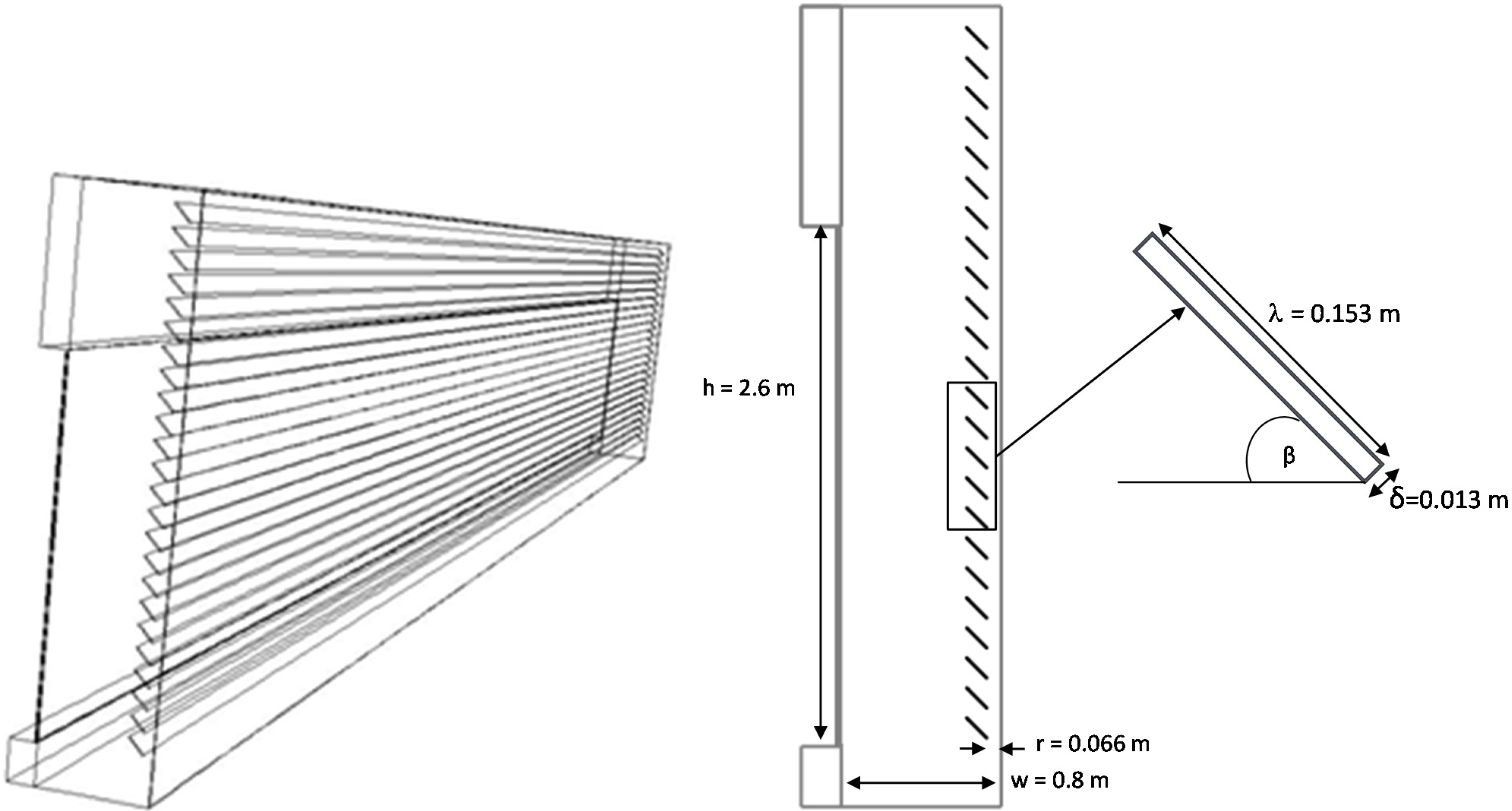
An isometric view and detail of the base geometric configuration used for this numerical study is shown in
Figure 1. The control volume comprises (from outdoors to indoors) an external glazing, a flow cavity with a venetian blind, an internal double glazing (52.5% of the internal façade area) and an internal wall (47.5% of the internal façade area). The flow cavity dimensions were set to 0.8 m wide, 4 m height and 24 m depth following fire hazard regulations of mandatory compliance in Spain [
25].
Figure 1.
Base geometry configuration for the studied DSF.
Figure 1.
Base geometry configuration for the studied DSF.
VB louvers tilt angle (β) was set to 45° in order to avoid glare risk due to direct daylighting into the building at high sun elevation angles. Previous studies by Gratia and de Herde [
26] suggest that the most efficient positions of shading devices in a DSF is in the middle of the cavity but that would be considered a fire hazard according to the local regulations [
25] as it blocks accessibility to the cavity in case of emergencies. For this study the VB was placed next to the external glazing, suggested by the aforementioned study as the second best location in terms of the thermal efficiency of the DSF [
26]. The geometrical model also distinguishes between the upper (facing outdoors) and the lower (facing indoors) surfaces of the VB louvers, which were created into the computational model as two separated wall boundary conditions for purposes of the parametric study presented.
3.2. Materials
Table 2 shows the physical and optical properties for all the DSF elements used in the parametric study base case. Thicknesses for the different layers were assigned following common practices in construction.
Table 2.
Thermo-physical and optical properties of the construction materials.
Table 2.
Thermo-physical and optical properties of the construction materials.
| Façade Element | ρ (kg/m3) | cp (J/kg·K) | k (W/m·K) | Absorptivity | Transmissivity | Thickness |
|---|
| Glass | 2.500 | 795 | 1.16 | 0.15 | 0.78 | 6 mm |
| Interior walls | 720 | 1.069 | 0.1 | 0.8 | - | 200 mm |
| VB louvers (Aluminum) | 2719 | 878 | 169 | 0.18 | - | δbc = 13 mm |
3.3. Location and Climatic Conditions of the DSF
It was assumed that the studied DSF was located in Barcelona, Spain (41.23° N–2.11° E) and facing south. Theoretical maximum values for solar irradiance (global and diffuse) and climatic data (for outdoors temperature) for a warm, sunny summer day (17th July) were taken from open-access databases [
27]. Time-dependency of the outdoors temperature for the selected operation date was fitted into a 6th-degree polynomial and introduced as a dynamic boundary condition to the CFD solver via user defined functions.
3.4. Construction and Operation Parameters Studied
The influence of several design and operation parameters in the thermal performance of a horizontally ventilated DSF with VB (measured in terms of solar gain reductions) was evaluated using CFD simulations. Details on the definition of the studied parameters, its base values and the parametric variations studied can be found in
Table 3. In order to properly assess the parameter effects on solar load gains all studied variables are presented as dimensionless quantities.
Table 3.
Parameters selected for numerical study.
Table 3.
Parameters selected for numerical study.
| Parameter | Definition | Base case value | Parametric variations |
|---|
| Absorptivity Louvers inner face | αi | αi,bc = 0.18 | αi = 0.3/0.6/0.9 |
| Emissivity Louvers outer face | ζo | ζo,bc = 0.1 | ζo = 0.4/0.6/0.8 |
| Louvers distance to outer glass | (Figure 1) | | R = 0.0450/0.0575/0.0700 |
| Cavity flow rate | | | 0.5663/0.7922/1.0000 |
3.5. Meshing and Boundary Conditions
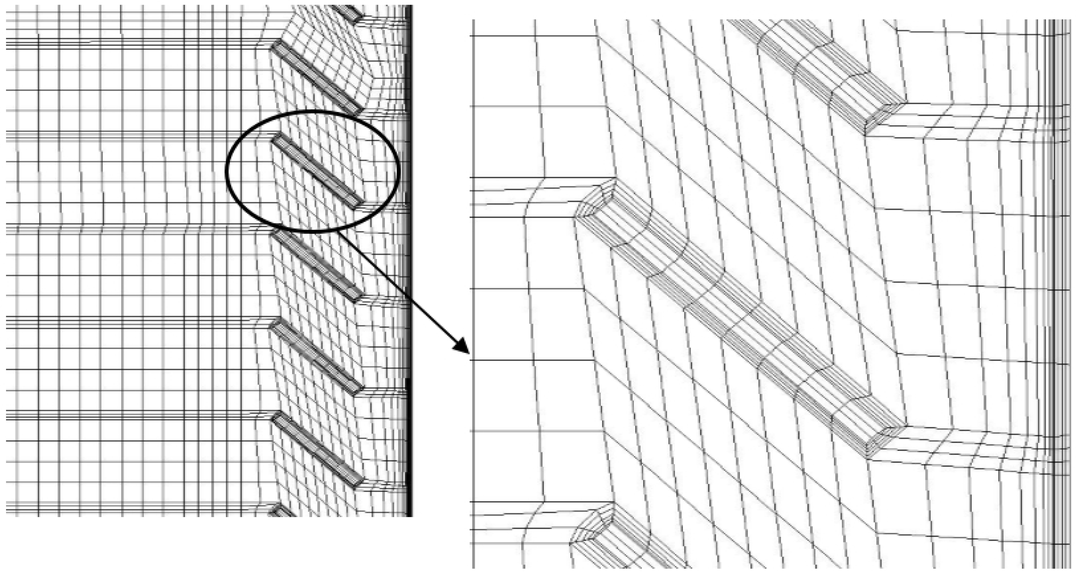
A structured hexahedral grid was selected as the computational mesh for all modeled cases (e.g.,
Figure 2). Mesh-sensitivity tests were performed in previous work [
3], selecting an optimal hexahedral mesh size of 2 × 12.5 × 1 mm for all solid phases. Boundary layers were defined around all solid surfaces in contact with a fluid to properly model the heat transfer phenomena. For the fluid phase (cavity), a new mesh-sensitivity test was performed considering the VB. Three different mesh densities were tested (2500, 3500 and 4500 kel) obtaining similar results in terms of heat fluxes for the two finer meshes tested. A cavity mesh of 3500 kel was selected for the purposes of this work.
Boundary conditions were set as close as possible to DSF regular operating conditions. Horizontal surfaces were set to adiabatic, reflective boundaries and the mass flow rate at the inlet was set to a constant value for each case. Thermal boundary conditions for the exterior and interior layers were imposed as convective + radiative heat fluxes and convective heat flux respectively. Convection coefficients were set to 12 W/m2K and 8 W/m2K for the outdoors and indoors glazing surfaces respectively. Radiative heat flux was computed using a radiation model.
Figure 2.
Detail of the mesh generated for the cavity and VB.
Figure 2.
Detail of the mesh generated for the cavity and VB.
3.6. Solver Set-up
RNG k-epsilon turbulence model and P1 radiation model were selected as numerical sub-models for all cases tested. Navier–Stokes equations together with the energy conservation equation were solved using the CFD code Ansys Fluent
® v15. A pressure-based double-precision transient solver was selected in order to solve the set of equations used. Second order upwind discretization schemes were imposed on all the transport equations. PISO pressure–velocity coupling was chosen due to its suitability for buoyancy-affected flows. The fluid was taken to be incompressible, Newtonian and in turbulent flow regime. All the numerical sub-models, discretization and simulation strategies were previously validated against an experimental database [
18]. Air properties were set to be temperature-dependent. A time step of 600 s was taken for performing the simulations.
Numerical simulations were performed in a Hybrid Bull machine property of Consorci de Serveis Universitaris de Catalunya (CSUC). Numerical convergence of the model was checked based on the normalized numerical residuals of all computed variables. Heat fluxes and temperatures on all solid surfaces were recorded for analysis and discussion purposes.
4. Results and Discussion
4.1. Velocity and Temperature Profiles inside the Cavity
For all the modeled cases, flow and temperature fields were obtained in order to qualitatively assess the DSF thermal performance.
Figure 3 and
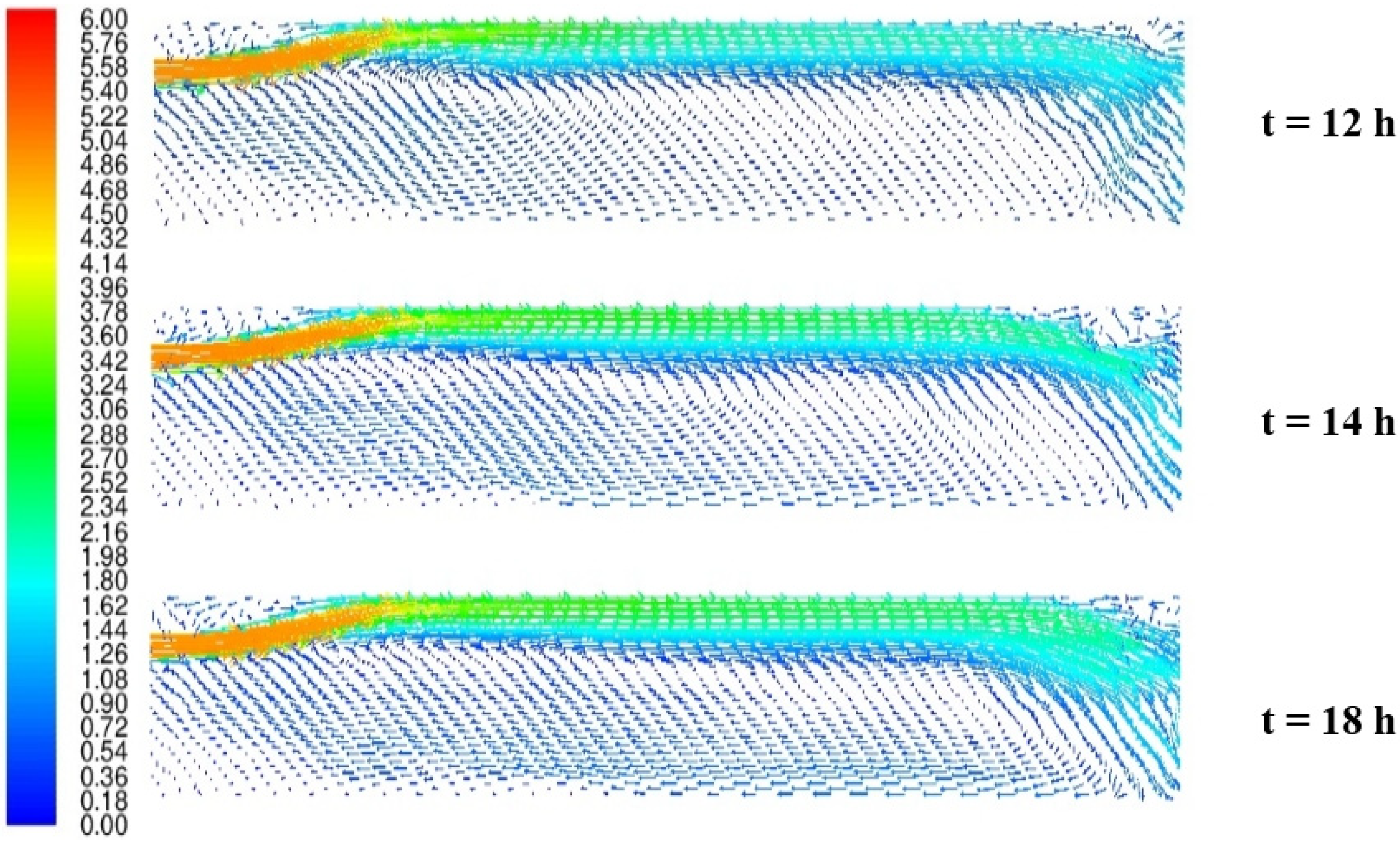
Figure 4 show the temperature and velocity profiles in a longitudinal mid-section of the flow cavity for different times of the day for the base case simulation. The velocity fields shown in
Figure 3 are similar to previously reported velocity fields for upper-crossed lateral ventilation schemes in DSF [
19,
20], which indicates that the VB has little effect on the inner cavity flow (between the VB and the inner wall). In the outer cavity (between the VB and the outdoor glass) the flow velocities obtained are low for all cases studies.
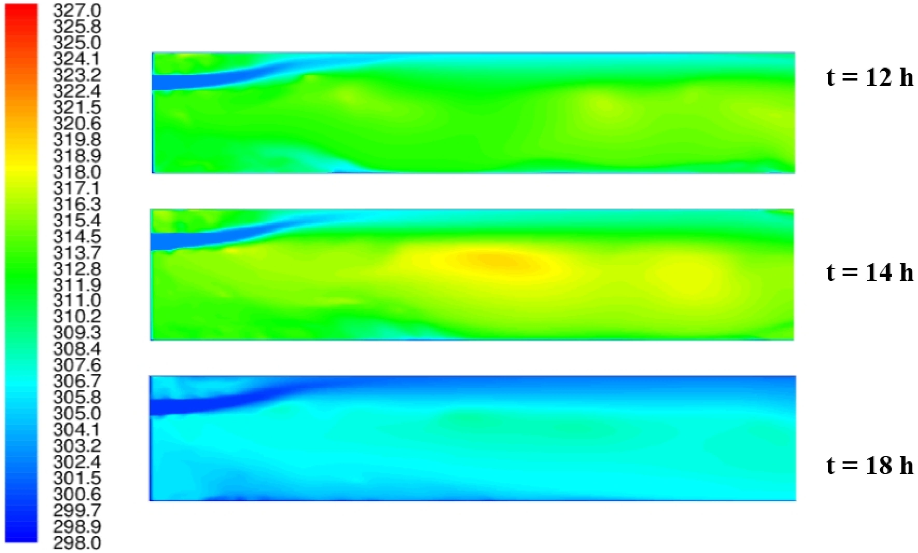
Temperature contours obtained for the base case (
Figure 4) show higher mid-cavity air temperatures than comparable results obtained for the same DSF model without VB [
19,
20]. This is directly related with the placement of opaque surfaces (VB louvers) in the cavity. These surfaces are the highest temperature zone of the cavity, affecting accordingly the temperature of its surroundings.
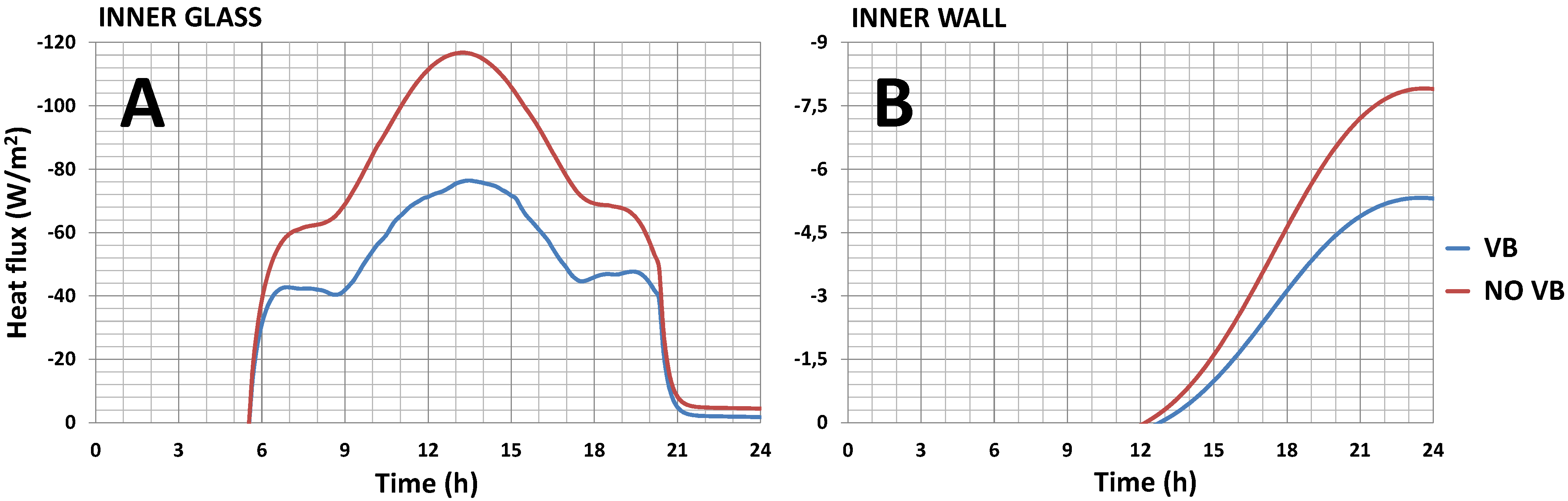
The effect of a VB on the indoor solar heat gain was evaluated using a set of numerical simulations of the DSF with/without a VB. For both scenarios, natural and forced ventilation operating conditions were studied. Heat flux through the interior surfaces of a DSF were recorded for a 24-hour period for all studied cases. These heat fluxes were integrated and area-weighted averaged to compute the solar heat gains. For the modeled cases with VB, the base case parameter values shown in
Table 3 were used.
Figure 5 shows examples of the heat flux recorded and
Table 4 presents the results obtained for this set.
Figure 3.
Mid-cavity velocity contours for the base case. Velocity scale in m/s.
Figure 3.
Mid-cavity velocity contours for the base case. Velocity scale in m/s.
Figure 4.
Mid-cavity temperature contours for the base case. Temperature scale in K.4.2. Effect of VB on Solar Heat Gains.
Figure 4.
Mid-cavity temperature contours for the base case. Temperature scale in K.4.2. Effect of VB on Solar Heat Gains.
Figure 5.
Heat flux through the inner glass (A) and inner wall (B) for a DSF with forced ventilation with and without VB.
Figure 5.
Heat flux through the inner glass (A) and inner wall (B) for a DSF with forced ventilation with and without VB.
Table 4.
Solar heat gains with and without VB.
Table 4.
Solar heat gains with and without VB.
| Solar heat gains (kJ/m2-day) | Natural ventilation | Forced ventilation |
|---|
| DSF without VB | 3173.4 | 2627.8 |
| DSF with VB | 2317.0 | 1708.1 (base case) |
| Reduction in solar heat gains | 27% | 35% |
As expected,
Table 4 shows that the use of a VB reduces the solar heat gains through the inner surfaces of the DSF. These reductions are not only due to the reflected radiation but also to the heat absorbed by the VB solid surfaces that is dissipated to the ventilation air, which may help explain the larger reductions obtained when forced ventilation is used instead of natural ventilation.
4.3. VB inner Surfaces Absorptivity
Double reflection can play an important role in heat and daylight transmission through a DSF [
28]. Reducing the double reflection can be achieved by modifying the VB inner surfaces absorptivity. Gray or pastel paints on aluminum surfaces are a low cost solution that offers an interesting range of absorptivities (0.2 < α
i < 0.9) [
29]. In order to evaluate the effect of the VB inner surface absorptivity on the thermal performance of the DSF, four absorptivity values within the suggested range were tested. Results obtained are shown in
Table 5.
Table 5.
Solar heat gains for different VB inner surface absorptivities.
Table 5.
Solar heat gains for different VB inner surface absorptivities.
| VB inner surface absorptivity | Solar heat gain (kJ/m2-day) | Reduction (%) |
|---|
| 0.18 | 1708.1 | |
| 0.3 | 1707.2 | 0.05 |
| 0.6 | 1700.9 | 0.42 |
| 0.9 | 1695.6 | 0.72 |
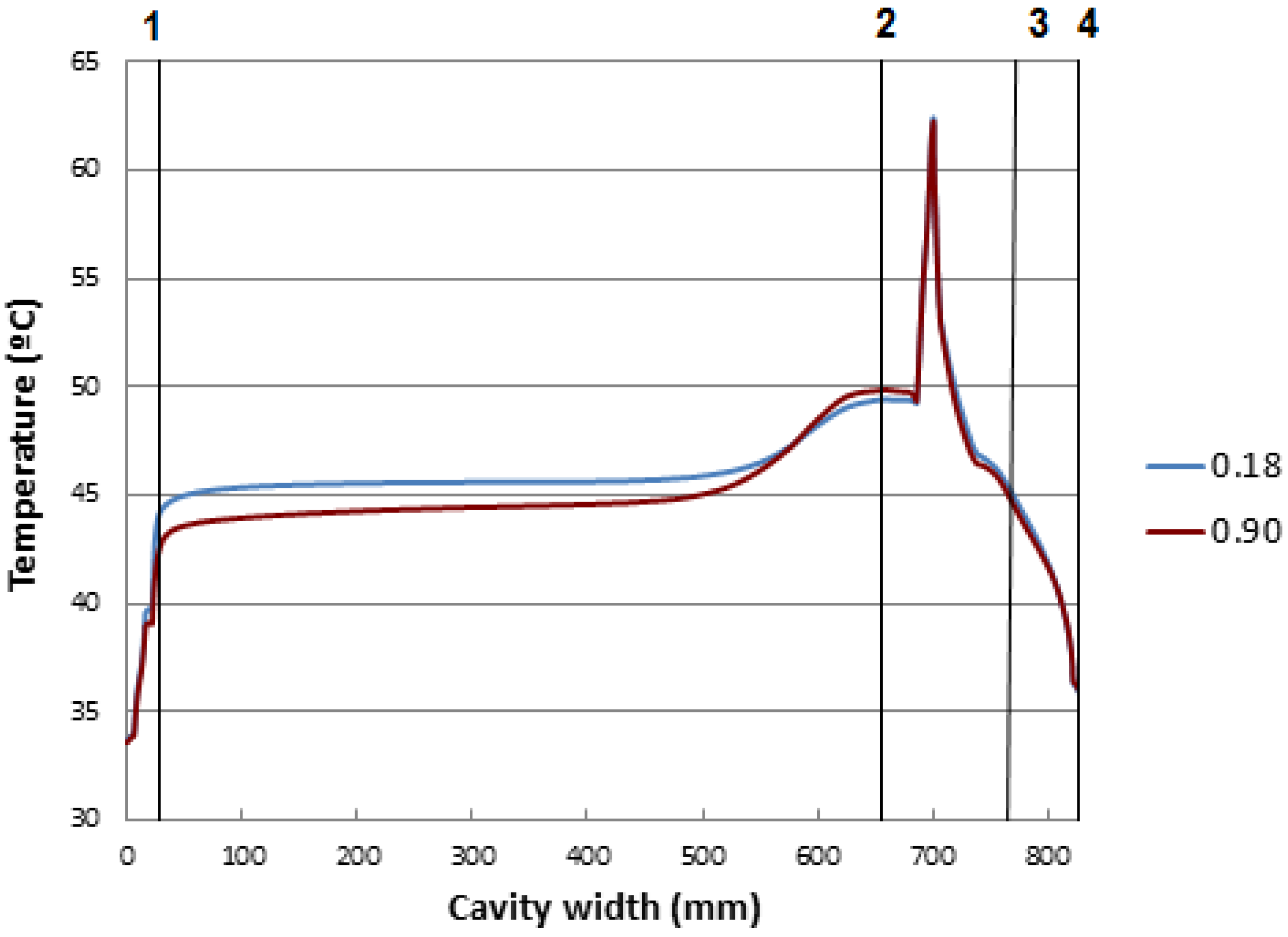
Results obtained show that increasing the absorptivity of the VB louvers inner (lower) surface reduces the heat flux through the DSF inner layer. Besides reducing double reflection effects, an increased absorptivity reduces the air temperature within the cavity (see
Figure 6).
Figure 6.
Temperature profile on a mid-cavity line for different VB inner surface absorptivities. (1) Indoors double glazing; (2–3) VB; (4) Outer glazing.
Figure 6.
Temperature profile on a mid-cavity line for different VB inner surface absorptivities. (1) Indoors double glazing; (2–3) VB; (4) Outer glazing.
This reduced cavity temperature may improve the DSF thermal performance by reducing the conductive/convective heat transfer towards the building interior.
4.4. VB Outer Surfaces Emissivity
Surface heat rejection is a desired quality for applications where avoiding heat transfer towards the interior is the goal. Increasing the heat rejection capability of a surface by modifying its emissivity is a regular subject of study in the aerospace industry. Dielectric film coatings on polished metals offer a wide range of emissivities [
29] that may be of application for an aluminum VB. In order to evaluate the effect of the VB outer surface emissivity on the thermal performance of the DSF, four emissivity values within the suggested range were tested. Results obtained are shown in
Table 6.
Table 6.
Solar heat gains for different VB outer surface emissivity.
Table 6.
Solar heat gains for different VB outer surface emissivity.
| VB outer face emissivity | Solar heat gain (kJ/m2-day) | Reduction (%) |
|---|
| 0.1 | 1708.1 | |
| 0.4 | 1687.4 | 1.21 |
| 0.6 | 1667.5 | 2.38 |
| 0.8 | 1666.6 | 2.43 |
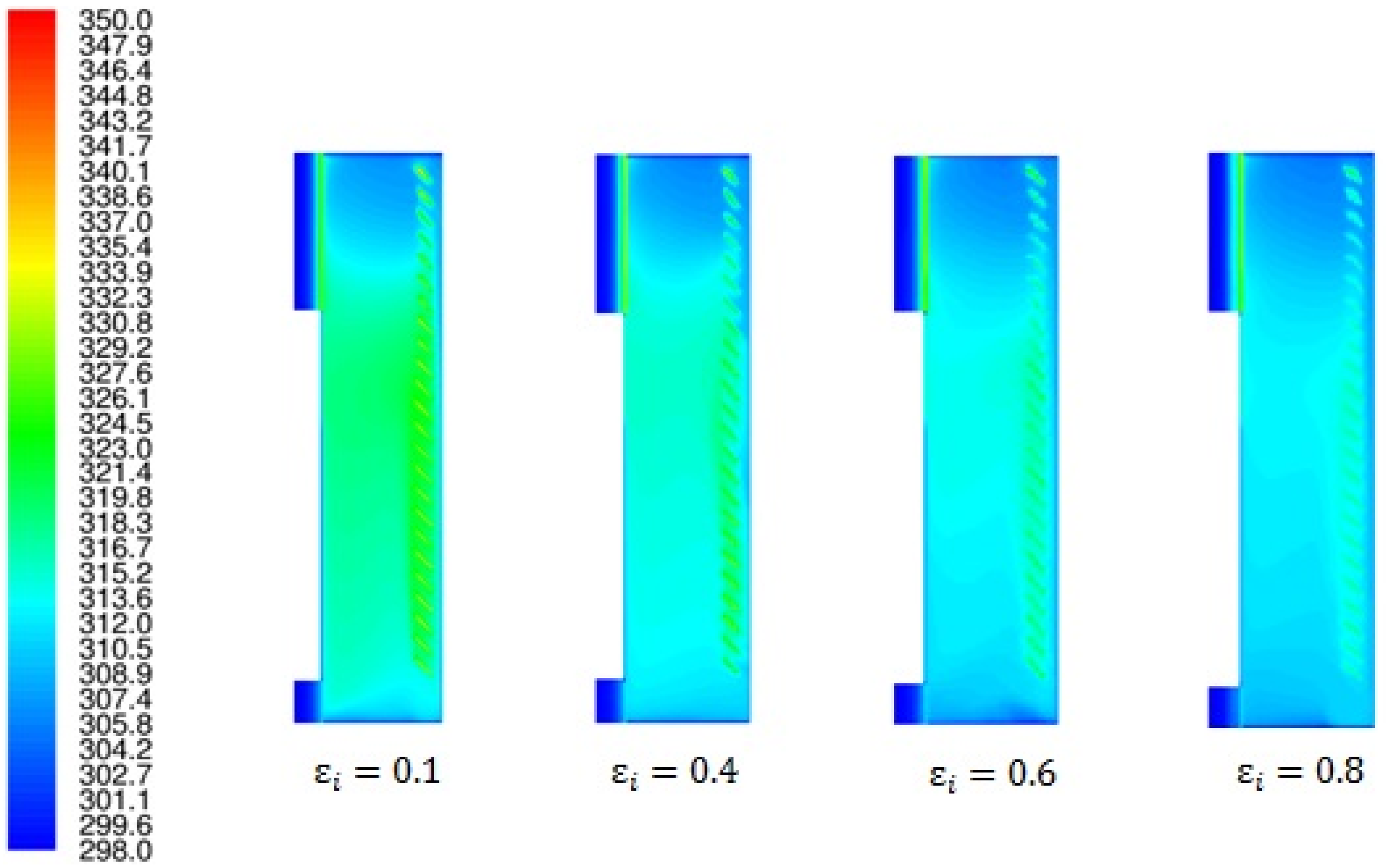
An enhanced emissivity allows the VB upper surfaces to dissipate the absorbed heat faster into the cavity air.
Figure 7 shows the temperature contours for a mid-cavity plane for different VB outer surface emissivities. Higher surface emissivities translate into lower surface temperatures, and thus lower cavity temperatures, reducing also the conductive/convective heat flux towards the interior.
Figure 7.
Temperature contours on a mid-cavity plane at 14h for different VB outer surface emissivities. Temperature scale in K.
Figure 7.
Temperature contours on a mid-cavity plane at 14h for different VB outer surface emissivities. Temperature scale in K.
4.5. VB Louver Distance to Outer Glass
The VB divides the cavity into an outer and an inner cavity. The outer cavity (comprised of between the outer layer and the VB) is a low-velocity to stagnation flow zone, while in the inner cavity the flow presents higher velocities due to the forced ventilation. Therefore is reasonable to expect that the relative size of the outer cavity with respect to the cavity width should have influence on the thermal performance of the DSF. In order to evaluate this effect, four VB positions within the cavity were tested. For this purpose, three new geometrical models and meshes were generated. The results obtained are shown in
Table 7.
Table 7.
Solar heat gains for different VB positions.
Table 7.
Solar heat gains for different VB positions.
| (Figure 1) | Solar heat gain (kJ/m2/day) | Reduction (%) |
|---|
| 0.0254 | 1708.1 | |
| 0.0215 | 1707.5 | 0.03 |
| 0.0177 | 1685.1 | 1.34 |
| 0.0138 | 1684.3 | 1.39 |
As it can be seen in the results shown in
Table 7, moving the VB closer to the outer glazing improves the DSF thermal performance.
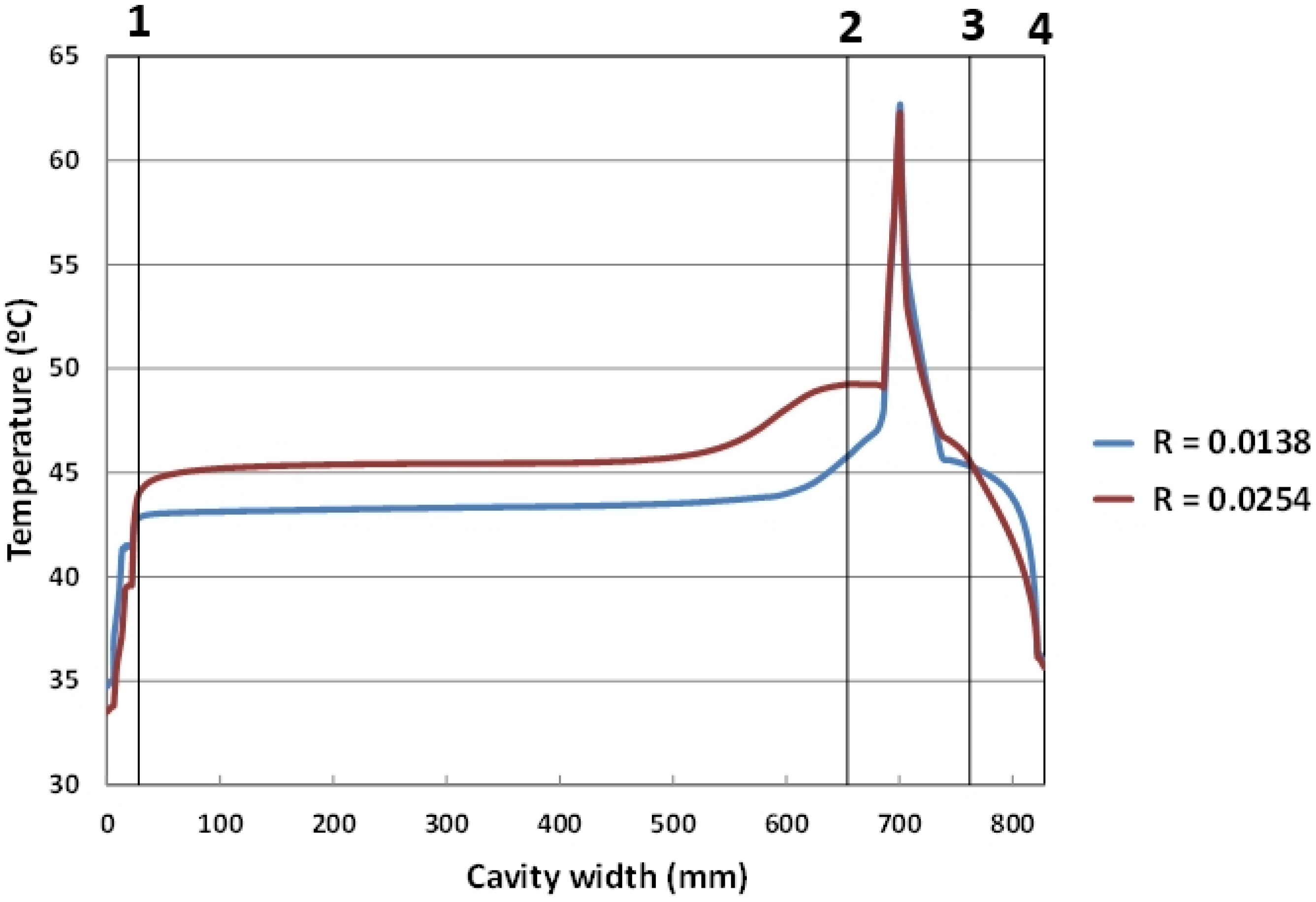
Figure 8 shows the temperature profiles on a mid-cavity line for the extreme positions tested. A small outer cavity (R = 0.0138) translates into higher outer cavity and lower inner cavity temperatures than a DSF with larger outer cavity (R = 0.0254). This favors the heat transfer from the outer cavity to the exterior and reduces the convective/conductive heat fluxes towards the interior of the DGF.
Figure 8.
Temperature profile on a mid-cavity line for different VB positions. (1) Indoors double glazing; (2–3) VB; (4) Outer glazing.
Figure 8.
Temperature profile on a mid-cavity line for different VB positions. (1) Indoors double glazing; (2–3) VB; (4) Outer glazing.
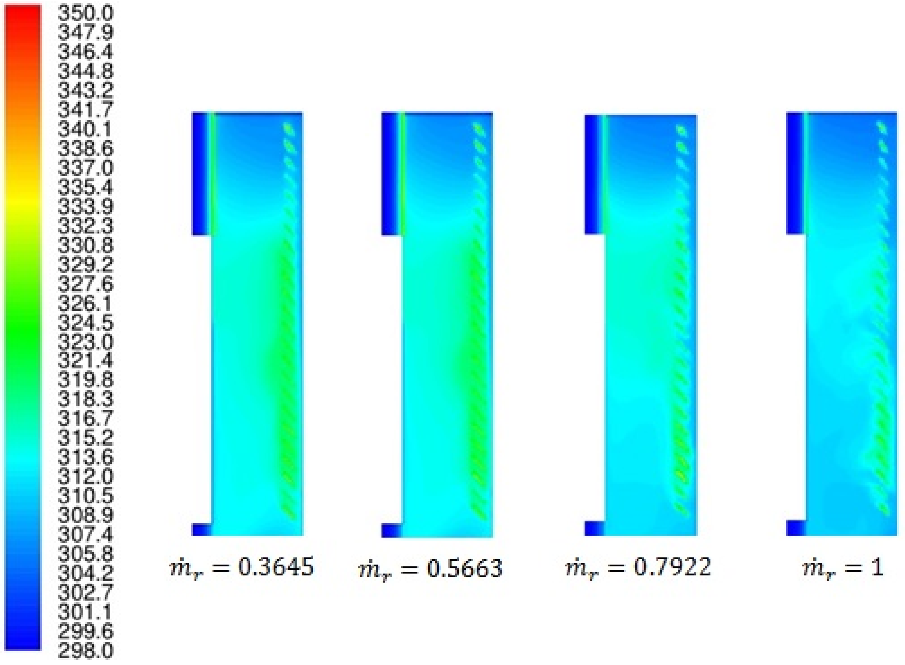
4.6. Forced Ventilation Flow Rate
Four different ventilation air flow rates (1.21, 1.88, 2.63 and 3.32 kg/s) were imposed to the computational model in order to evaluate the influence of the forced ventilation in the thermal performance of the DSF with VB. Results obtained are shown in
Table 8.
Table 8.
Solar heat gains for different ventilation flow rates.
Table 8.
Solar heat gains for different ventilation flow rates.
| Solar heat gain (kJ/m2-day) | Reduction (%) |
|---|
| 0.3645 | 1708.1 | |
| 0.5663 | 1706.1 | 0.11 |
| 0.7922 | 1696.0 | 0.70 |
| 1.0000 | 1685.9 | 1.30 |
Figure 9.
Temperature contours on a mid-cavity plane at 14 h for different ventilation flow rates. Temperature scale in K.
Figure 9.
Temperature contours on a mid-cavity plane at 14 h for different ventilation flow rates. Temperature scale in K.
As expected, a higher ventilation flow rate reflects into better DSF thermal performance. It is important to notice that almost tripling the ventilation flow rate only improves the performance of the base case by 1.30%, which is a small solar heat gain reduction considering the higher operational costs associated with higher ventilation flow rates.
5. Conclusions and Future Work
CFD proves to be a useful tool when modeling conductive/convective/radiative heat transfer in ventilated DSF. Numerical simulations were run for several cases and velocity and temperature fields together with heat fluxes through all surfaces were obtained for the studied scenarios. A previously validated modeling strategy [
3,
18] was used to obtain the presented results, consolidating the idea that CFD can offer tailored solutions for DSF performance optimization.
Heat fluxes through the inner layer of a DSF were evaluated for a DSF with/without VB in natural and forced ventilation operating conditions in order to assess the influence of VB on DSF thermal performance. Results obtained show that a VB can reduce solar heat gains up to 35%. These reductions are not only due to the reflected radiation but also to the heat absorbed by the VB solid surfaces that is dissipated to the ventilation air, which may help explain the larger reductions obtained when forced ventilation is used instead of natural ventilation.
The effects of several parameters as VB’s inner surface absorptivity, outer surface emissivity and its distance to the outer glass as well as the forced ventilation flow rate on the thermal performance of a DSF were studied using single-parameter variation simulation sets. It was found that increasing the VB outer surfaces emissivity (i.e., using dielectric film coatings) or VB inner surfaces absorptivity (i.e., using pastel/gray paints) can improve the thermal performance of the DSF due to the enhancement of heat rejection towards outdoors and the reduction of double reflection towards indoors. VB distance to the outer glass can also affect the thermal performance of the façade, as the solar heat gains are lower when the VB is closer to the outer glazing. Increasing the ventilation flow rate can also reduce the DSF solar heat gains, but the thermal benefits obtained by higher flow rates may be overshadowed by the operating costs associated with the ventilation equipment required to achieve these ventilation rates.
Future work should include the evaluation and parametrization of the effects of other shading elements as textile curtain walls or micro-perforated materials in the thermal performance of DSF in Mediterranean climates.
Acknowledgments
The authors acknowledge the economic support received from Grupo JG Consultora de Proyectos S.A., Catedra UPC-JG and Universitat Internacional de Catalunya. Funding from the Spanish Ministry of Economy and Competitiveness (Grant DPI2012-36264) is also appreciated. The authors also acknowledge Consorci de Serveis Universitaris de Catalunya (CSUC) for granting access to their supercomputing facilities for developing this work.
Author Contributions
Eduard Egusquiza and Pere Alavedra conceived and designed the numerical experiments; Jordi Parra performed the numerical experiments; Alfredo Guardo analyzed the data and wrote the paper.
Nomenclature
| a | Absorption coefficient | m−1 |
| cp | Specific heat | J·kg−1·K−1 |
| D | Louvers shape factor | |
| Fb | External specific body forces | kg·m−2·s−2 |
| Fw,∞ | Radiation shape factor | |
| g | Gravity forces | m·s−2 |
| h | Heat transfer coefficient | W·m−2·K−1 |
| k | Thermal conductivity | W·m−1·K−1 |
| L | Characteristic length | m |
| | Louvers width | m |
| mr | Flow rate parameter | |
| p | Static pressure | Pa |
| Heat flux | W·m−2 |
| r | Louvers distance to outer glass | m |
| R | Louvers position parameter | |
| SL | Solar load gain | J·m−2 |
| t | Time | s |
| T | Static temperature | K |
| u | Velocity | m·s−1 |
| w | Cavity width | m |
| Greek Letters | | |
| α | Absorptivity | |
| β | Louvers tilt angle | |
| δ | Louvers thickness | m |
| ζ | Emissivity | |
| λ | Louvers width | m |
| µ | Dynamic viscosity | kg·m−1·s−1 |
| ρ | Fluid density | kg·m−3 |
| σ | Stefan-Boltzmann constant | W·m−2·K−4 |
| τ | Stress tensor | N·m−2 |
| Φ | Normalized solar load gain | |
| χ | Parameter value | |
| Dimensionless Groups | | |
| Bi | Biot number | [h · L · kw−1] |
| Br | Brinkman number | [µ · u2 · kf−1 · T−1] |
| Ec | Eckert number | [u2 · Cp−1 · T−1], [Br.Pr−1] |
| Eu | Euler number | [δp · ρ−1 · u−2] |
| Fr | Froude number | [u2 · L−1 · g −1] |
| Ma | Mach number | [u · usound−1] |
| Nu | Nusselt number | [h · L· kf−1] |
| Pr | Prandtl number | [cp · µ · kf−1] |
| Re | Reynolds number | [L· u · ρ · µ−1] |
| Sr | Strouhal number | [L · t−1 · u−1] |
| Th | Thring number | [ρ ·cp · u · ζ−1 · σ−1 · T−3] |
| Acronyms | | |
| CFD | Computational fluid dynamics | |
| DSF | Double skin façade(s) | |
| VB | Venetian blind(s) | |
| Sub/Super—Index | | |
| 0 | Referred to a reference quantity | |
| ^ | Referred to a dimensionless quantity | |
| bc | Referred to the base case | |
| case | Referred to the studied simulation case | |
| f | Referred to a fluid | |
| fc | Referred to the free convection case | |
| i | Referred to an inner/indoors position | |
| o | Referred to an outer/outdoors position | |
| rad | Referred to radiation | |
| T | Referred to a turbulent quantity | |
| w | Referred to a wall | |
Conflicts of Interest
The authors declare no conflict of interest.
References
- Poirazis, H. Double Skin Façades for Office Buildings; Report EBD-R—04/3; Lund Institute of Technology, Lund University: Lund, Sweden, 2004. [Google Scholar]
- Gratia, E.; de Herde, A. Optimal operation of a south double-skin façade. Energy Build. 2004, 36, 41–60. [Google Scholar] [CrossRef]
- Guardo, A.; Coussirat, M.; Egusquiza, E.; Alavedra, P.; Castilla, R. A CFD approach to evaluate the influence of construction and operation parameters on the performance of active transparent façades in Mediterranean climates. Energy Build. 2009, 41, 534–542. [Google Scholar] [CrossRef]
- Phillips, J.; Naylor, D.; Oosthuizen, P.H.; Harrison, S.J. Modeling of the conjugate heat transfer from a window adjacent to a louvered shade. In Proceedings of the 6th International Conference on Advanced Computational Methods in Heat Transfer, Madrid, Spain, 10–14 March 2002.
- Collins, M.R.; Harrison, S.J.; Oosthuizen, P.H.; Naylor, D. Heat transfer from an isothermal vertical surface with adjacent heated horizontal louvers: Numerical analysis. ASME J. Heat Transf. 2002, 124, 1072–1077. [Google Scholar] [CrossRef]
- Collins, M.R.; Harrison, S.J.; Oosthuizen, P.H.; Naylor, D. Heat transfer from an isothermal vertical surface with adjacent heated horizontal louvers: Validation. ASME J. Heat Transf. 2002, 124, 1078–1087. [Google Scholar] [CrossRef]
- Athienitis, A.; Santamouris, M. Thermal Analysis and Design of Passive Solar Buildings; James & James Science Publishers Ltd.: London, UK, 2002. [Google Scholar]
- Collins, M.R.; Harrison, S.J. Calorimetric analysis of the solar and thermal performance of windows with interior louvered blinds. ASHRAE Trans. 2004, 110, 474–485. [Google Scholar]
- Chantrasrisalai, C.; Fisher, D.E. An in situ experimental method for the development and validation of slat-type blind models in cooling load calculations. J. Sol. Energy Eng. 2006, 128, 189–198. [Google Scholar] [CrossRef]
- Manz, H.; Menti, U. Energy performance of glazings in European climates. Renew. Energy 2012, 37, 226–232. [Google Scholar] [CrossRef]
- Tzempelikos, A.; Athienitis, A. The impact of shading design and control on building cooling and lighting demand. Sol. Energy 2007, 81, 369–382. [Google Scholar] [CrossRef]
- Tzempelikos, A. The impact of Venetian blind geometry and tilt angle on view, direct light transmission and interior illuminance. Sol. Energy 2008, 82, 1172–1191. [Google Scholar] [CrossRef]
- Oh, M.H.; Lee, K.H.; Yoon, J.H. Automated control strategies of inside slat-type blind considering visual comfort and building energy performance. Energy Build. 2012, 55, 728–737. [Google Scholar] [CrossRef]
- Glória Gomez, M.; Santos, A.J.; Moret Rodrigues, A. Solar and visible optical properties of glazing systems with venetian blinds: Numerical, experimental and blind control study. Build. Environ. 2014, 71, 47–59. [Google Scholar] [CrossRef]
- Manz, H. Total solar energy transmittance of glass double façades with free convection. Energy Build. 2004, 36, 127–136. [Google Scholar] [CrossRef]
- Manz, H.; Schaelin, A.; Simmler, H. Airflow patterns and thermal behavior of mechanically ventilated glass double façades. Build. Environ. 2004, 39, 1023–1033. [Google Scholar] [CrossRef]
- Sedlák, J.; Mráček, P. Simulation of the double facade in the Brno Metropolitan Library. In Proceedings of the Dynastee 2005. Dynamic Analysis, Simulation and Testing Applied to the Energy and Environmental Performance of Buildings, Athens, Greece, 12–14 October 2005.
- Coussirat, M.; Guardo, A.; Jou, E.; Egusquiza, E.; Cuerva, E.; Alavedra, P. Performance and influence of numerical sub-models on the CFD simulation of free and forced convection in double-glazed ventilated façades. Energy Build. 2008, 40, 1781–1789. [Google Scholar] [CrossRef]
- Guardo, A.; Coussirat, M.; Valero, C.; Egusquiza, E.; Alavedra, P. CFD assessment of the performance of lateral ventilation in double glazed façades in Mediterranean climates. Energy Build. 2011, 43, 2539–2547. [Google Scholar] [CrossRef]
- Valentín, D.; Guardo, A.; Egusquiza, E.; Valero, C.; Alavedra, P. Use of Coandă nozzles for double glazed façades forced ventilation. Energy Build. 2013, 62, 605–614. [Google Scholar] [CrossRef]
- Valentín, D.; Guardo, A.; Egusquiza, E.; Valero, C.; Alavedra, P. Assessment of the economic and environmental impact of double glazed façade ventilation systems in Mediterranean climates. Energies 2013, 6, 5069–5087. [Google Scholar] [CrossRef] [Green Version]
- Baldinelli, G. Double skin façades for warm climate regions: Analysis of a solution with an integrated movable shedding system. Build. Environ. 2009, 44, 1107–1118. [Google Scholar] [CrossRef]
- Safer, N.; Woloszyn, M.; Roux, J.J. Three-dimensional simulation with a CFD tool of the airflow phenomena in single floor double-skin facade equipped with a venetian blind. Sol. Energy 2005, 79, 193–203. [Google Scholar] [CrossRef]
- Zeng, Z.; Li, X.; Zhu, Y. Modeling ventilation in naturally ventilated double-skin façade with a Venetian blind. Build. Environ. 2012, 57, 1–6. [Google Scholar] [CrossRef]
- Código Técnico de la Edificación, Real Decreto 314/2066 del 17 de marzo. Sección S1 5, Apartado 2. Gobierno de España. Available online: http://www.codigotecnico.org/cte/export/sites/default/web/galerias/archivos/DB_SI_19feb2010.pdf (accessed on 19 April 2015). (In Spanish)
- Gratia, E.; de Herde, A. The most efficient position of shading devices in a double-skin façade. Energy Build. 2007, 39, 364–373. [Google Scholar] [CrossRef]
- Mitjà, A. Atlas de Radiació Solar a Catalunya; Institut Català d’Energia: Barcelona, Spain, 2001. [Google Scholar]
- Chan, Y.C.; Tzempelikos, A. Efficient Venetian blind control strategies considering daylight utilization and glare protection. Sol. Energy 2013, 98, 241–254. [Google Scholar] [CrossRef]
- Gilmore, D.G. Spacecraft Thermal Control Handbook, Volume I: Fundamental Technologies, 2nd ed.; American Institute of Aeronautics and Astronautics: Reston, CA, USA, 2002; pp. 139–159. [Google Scholar]
© 2015 by the authors; licensee MDPI, Basel, Switzerland. This article is an open access article distributed under the terms and conditions of the Creative Commons Attribution license (http://creativecommons.org/licenses/by/4.0/).


