1. Introduction
Heat sources are an important source of energy, which can be harvested for driving electronic devices and systems. For example, solar radiation can be directly utilized as a thermal energy source for powering many devices and systems. Solar thermoelectric generators produce an electro-motive force using the Seebeck effect. Direct energy conversion using thermoelectric generators mainly relies on this effect to convert a steady-state temperature difference at the junction of two dissimilar metals or semiconductors into an electromagnetic force or electrical energy. Thermoelectric generators need fixed temperature differences, and cannot generally work in environments with spatially uniform and time-dependent temperature fluctuations with short periods. Alternatively, pyroelectric devices can directly convert time-dependent temperature oscillations into electricity [
1,
2,
3]. Pyroelectricity is a property whereby a charge is generated on the surface of pyroelectric materials as a result of a change in temperature, and manifests itself in polar materials due to the temperature dependence of its electrical polarization. The direction of the pyroelectric current changes with the changing nature of the thermal gradient. When the temperature of pyroelectric materials increases (dT/dt > 0), polarization decreases due to the re-orientation of the dipole moment, resulting in an electrical current in an external circuit. Conversely, when the temperature of pyroelectric materials decreases (dT/dt < 0), polarization increases as dipoles gain their orientation. This also results in an electrical current in the reverse direction. Hence, utilization of the pyroelectric effect for energy generation from solar temporal variations looks to be a promising strategy. The pyroelectric current is given by [
4,
5]:
where η is the absorption coefficient of radiation; A is the electrode area; dT/dt is the temperature variation rate of the pyroelectric materials; Q is the induced charge;
tt and
tb are, respectively, the considered terminal and beginning times; and P is the pyroelectric coefficient of the pyroelectric materials given by:
where P
s is the magnitude of the electrical polarization vector. Pyroelectric cells are sandwiched between the top and bottom electrodes, as flat-plate capacitors, and poled along the axis perpendicular to the plates. P
s is perpendicular to the electrode surface when its magnitude is equal to the electrode charge density. The thermal-isolation structure, pyroelectric material properties, electrode layout and absorption coefficient of the pyroelectric materials are the most important factors for enhancing qualities. From Equation (1), it can be seen that a higher temperature variation rate in the pyroelectric cells leads to a higher response current in the pyroelectric devices. However, the temperature variation rate is difficult to extract from pyroelectric layers by experimental measurement. Some finite element models have been built using the commercial software package COMSOL to explore the temperature variation rate in pyroelectric cells, with cavities by wet etching, trenches by a precision dicing saw and grooves by sandblast etching designed to improve the energy conversion efficiency of PZT pyroelectric cells by pyroelectricity [
6,
7,
8]. Therefore, pyroelectric materials with high P values and applications with large temperature variations over time should be considered. Moreover, increasing the surface of the pyroelectric cells produces an increase in the current at parity with the incident thermal power density per unit area.
Moreover, the great challenge for pyroelectric energy harvesting lies in finding promising temperature variations or an alternating thermal loading in real situations. Although Zhang
et al. [
9] developed a proposal for integrating solar radiation and wind flow fluctuation to drive pyroelectric generators, a strong and a weak wind, respectively, were used to bring about temperature variation rates by strong forced and natural convection. However, the temperature variation rates in pyroelectric cells could not be obvious due to the uncertain wind velocity. Furthermore, the pyroelectric cells could not be periodically and consecutively heated and cooled. In this research, we have proposed a novel pyroelectric harvester integrating solar radiation with wind power by the pyroelectric effect. Solar radiation is a thermal source, and wind is a dynamic potential. A disk generator was used to harvest wind power. A mechanism was considered to convert the rotation energy of the disk generator to drive a shutter for generating temperature variations in pyroelectric cells (Lead Zirconate Titanate, PZT) by means of a planetary gear system. The temperature variation rate in the pyroelectric cells was generated by a shutter designed to transmitted airflow. The objectives of this research were the design and construction of a pyroelectric harvester driven by solar radiation and wind power. The performance of the harvester was analyzed in terms of optimizing the work cycle of pyroelectric cells under a controlled airflow.
3. Results and Discussion
Pyroelectric energy conversion requires a periodic temperature profile applied to pyroelectric cells in order for the resulting temperature fluctuations to generate an electrical output. The critical consideration in the periodic temperature profile is the frequency or work cycle, which is related to environmental conditions, radiation power and material properties, as well as the dimensions and structure of the pyroelectric cells. Therefore, the efficient period band was first investigated in order to increase the efficiency of the power output. The planetary gear system was used to connect the disk generator and the shutter. The disk generator needed a higher rotational speed to generate the electrical output, while the pyroelectric harvester needed a lower rotational speed. The planetary gear system was designed as a reducer, with a speed reduction ratio of 1:36 by a two-gear train reduction while the input from the disk generator was set in the sun gear and the output to the shutter was set in the planet pinions under the ring gear fixed. Although the speed reduction ratio was a constant, the ratio was decided in a light breeze environment. In a higher wind speed, the disk generator was the main force generating the electrical output. In a lower wind speed, the proposed pyroelectric harvester played a complementary role by generating the electrical output when the efficiency of the disk generator was low. Therefore, the proposed pyroelectric harvester possessed a complementary function in cooperating with the disk generator in the electric output generation.
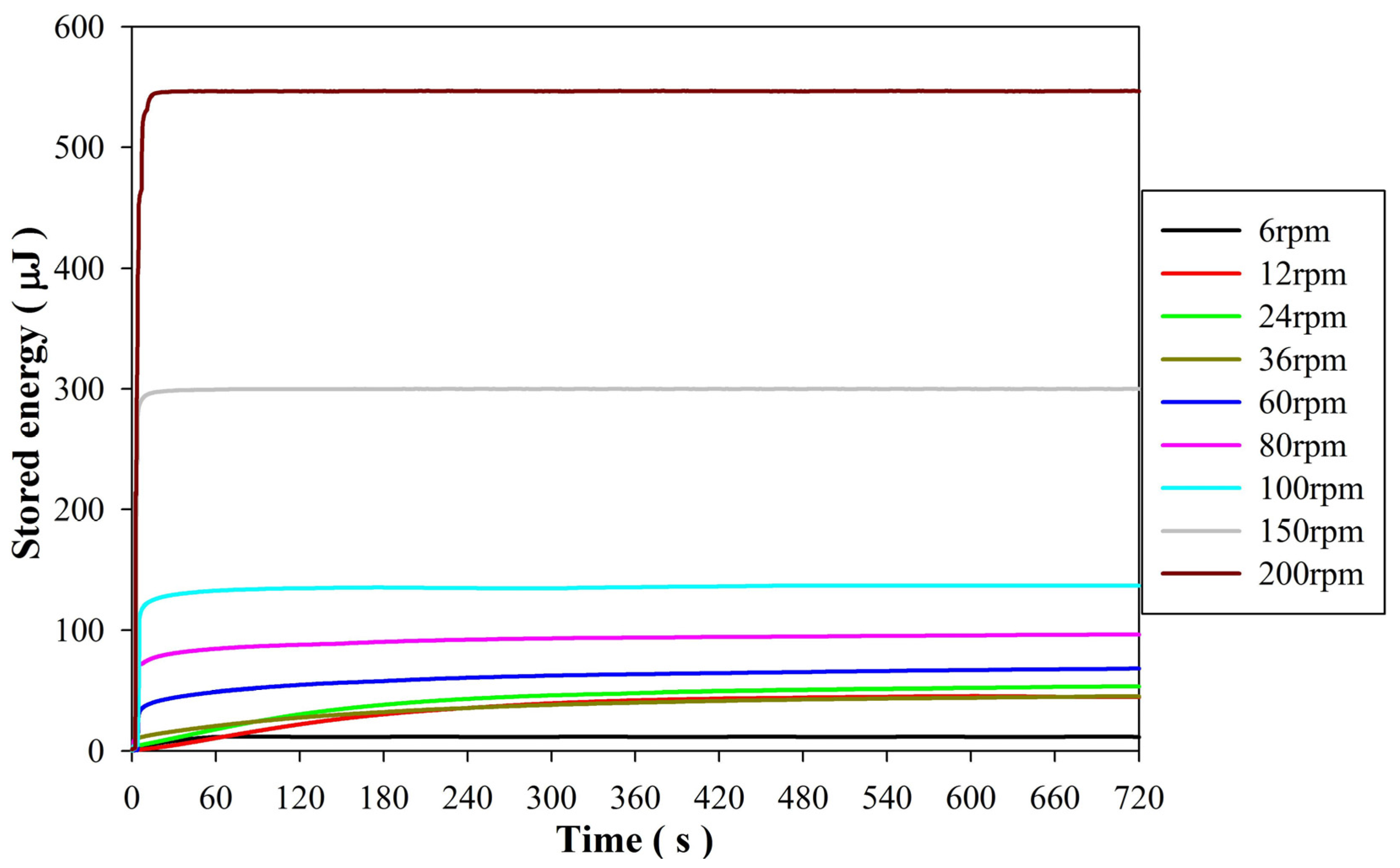
Figure 5 shows the stored energy in the storage capacitor of 10 μF through a full-wave rectifier acquired from the disk generator under various rotational speeds. It was revealed that the stored energy rate and the stable stored energy increased as the rotational speed of the disk generator increased. This presented a larger promotion in the stored energy rate and the stable stored energy when the rotational speed of the disk generator was greater than 100 RPM. Moreover, the energy storage efficiency was greatly reduced when the rotational speed was lower than 100 RPM in a light wind speed of 3.1 m/s. Moreover,
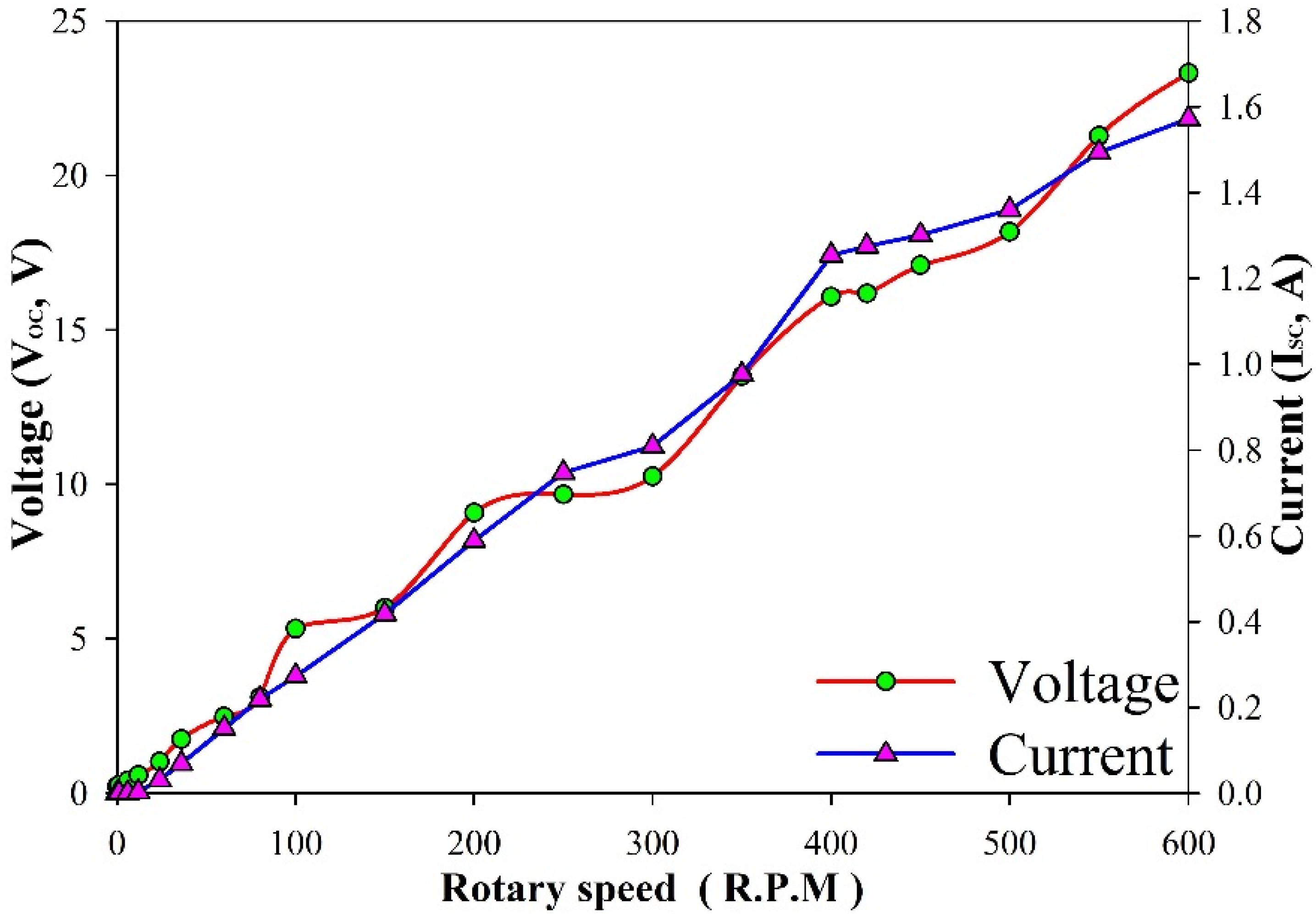
Figure 6 shows the open-circuit voltage (V
OC) and the short-circuit current (I
SC) of the disk generator. The electrical outputs of the disk generator were proportional to rotational speeds, except when the rotational speed of the disk generator was lower than 40 RPM. Therefore, the pyroelectric harvester plays a complementary role when the disk generator is inactive. The speed reduction ratio of the planetary gear system, about 1:36, was used to reduce the rotational speed of the disk generator so as to match the longer period of the PZT pyroelectric harvester in situations of a weaker wind source.
Figure 5.
Stored energy in the 10 μF storage capacitor from the disk generator under various rotational speeds.
Figure 5.
Stored energy in the 10 μF storage capacitor from the disk generator under various rotational speeds.
Figure 6.
The open-circuit voltage and the short-circuit current of the disk generator under various rotational speeds.
Figure 6.
The open-circuit voltage and the short-circuit current of the disk generator under various rotational speeds.
The radiating heat lamp with the shutter resulted in temperature fluctuations in the range from 65 °C to 75 °C.
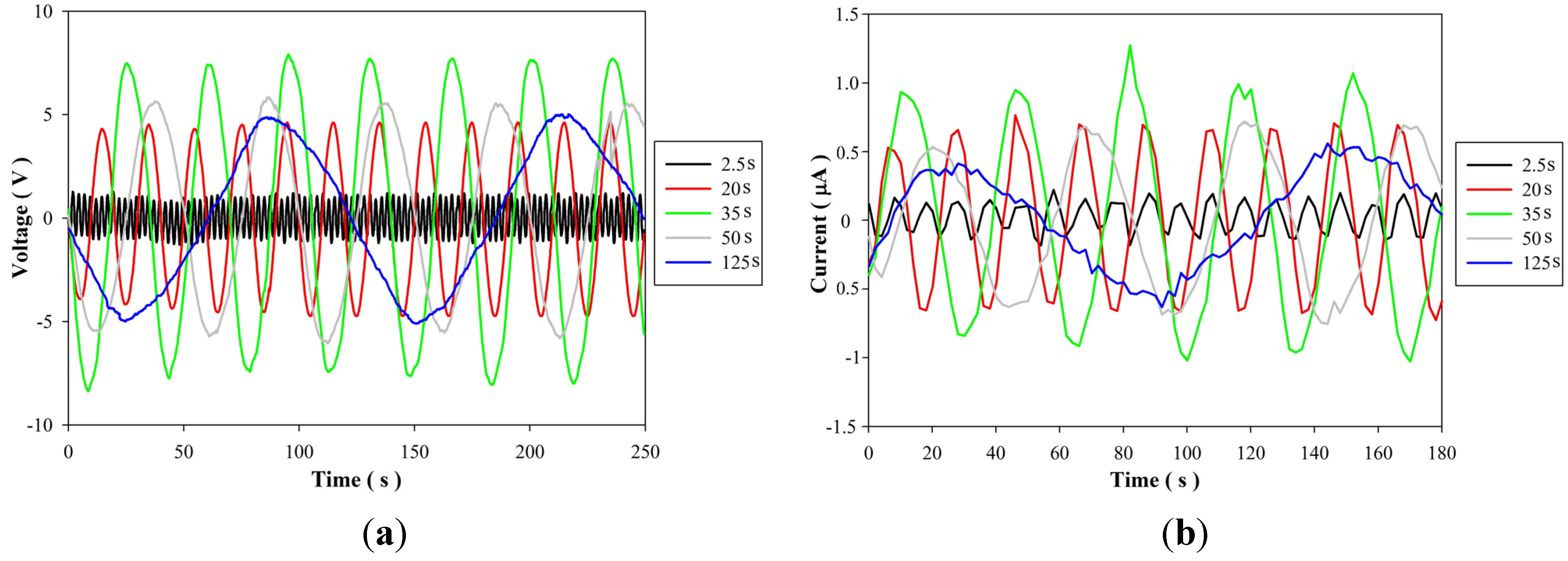
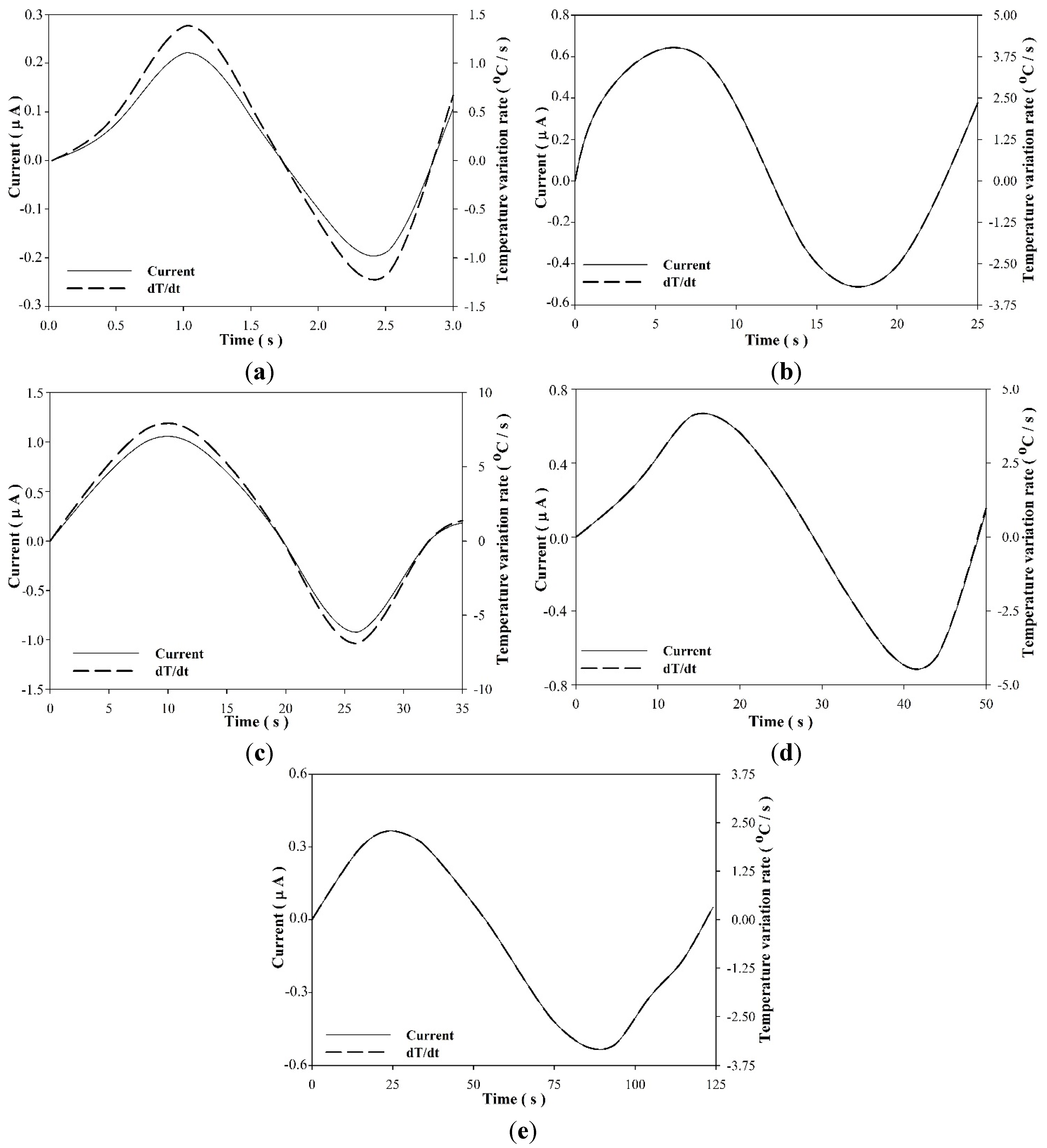
Figure 7 shows the relationships between voltage, current and time for five periods, 2.5 s, 20 s, 35 s, 50 s and 125 s, when using the PZT pyroelectric harvester. It was obvious that the curves had the best peak value at about 35 s. The induced current was also proportional to temperature variation rates according to Equation (1), as shown in
Figure 8. The optimal electrical output attributed to the largest temperature variation rate at about 35 s. The induced current and the temperature variation rate presented an appearance of time delay in the shorter periods of 2.5 s and 20 s due to the thermal capacity of the PZT cell. The induced charge was inferred from the integration of the area under the current curves by a numerical integration of Simpson’s rule.
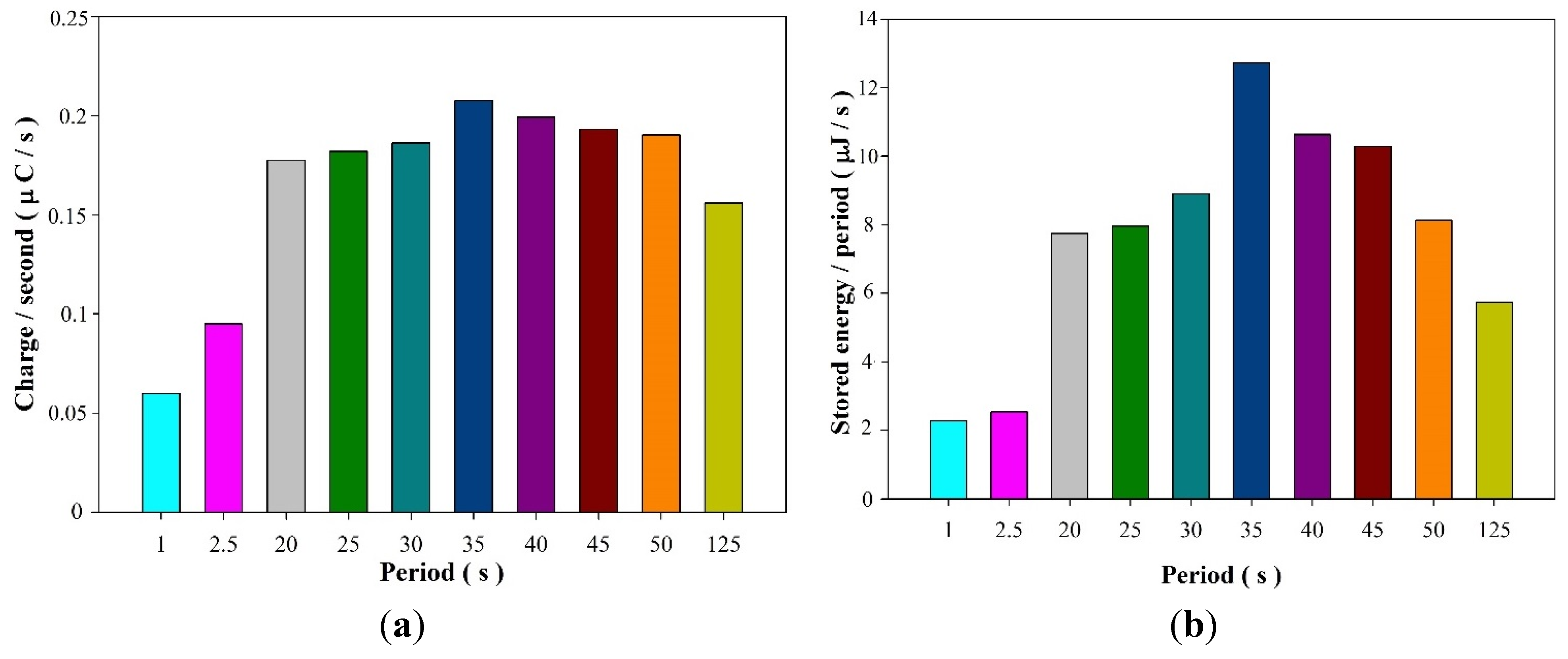
Figure 9 shows the relationships between the induced charge per second and the stored energy per period in the 10 μF electrolytic capacitor at various period times when using the PZT pyroelectric harvester. The optimal period was also about 35 s for generating the best performance in the induced charge and the stored energy.
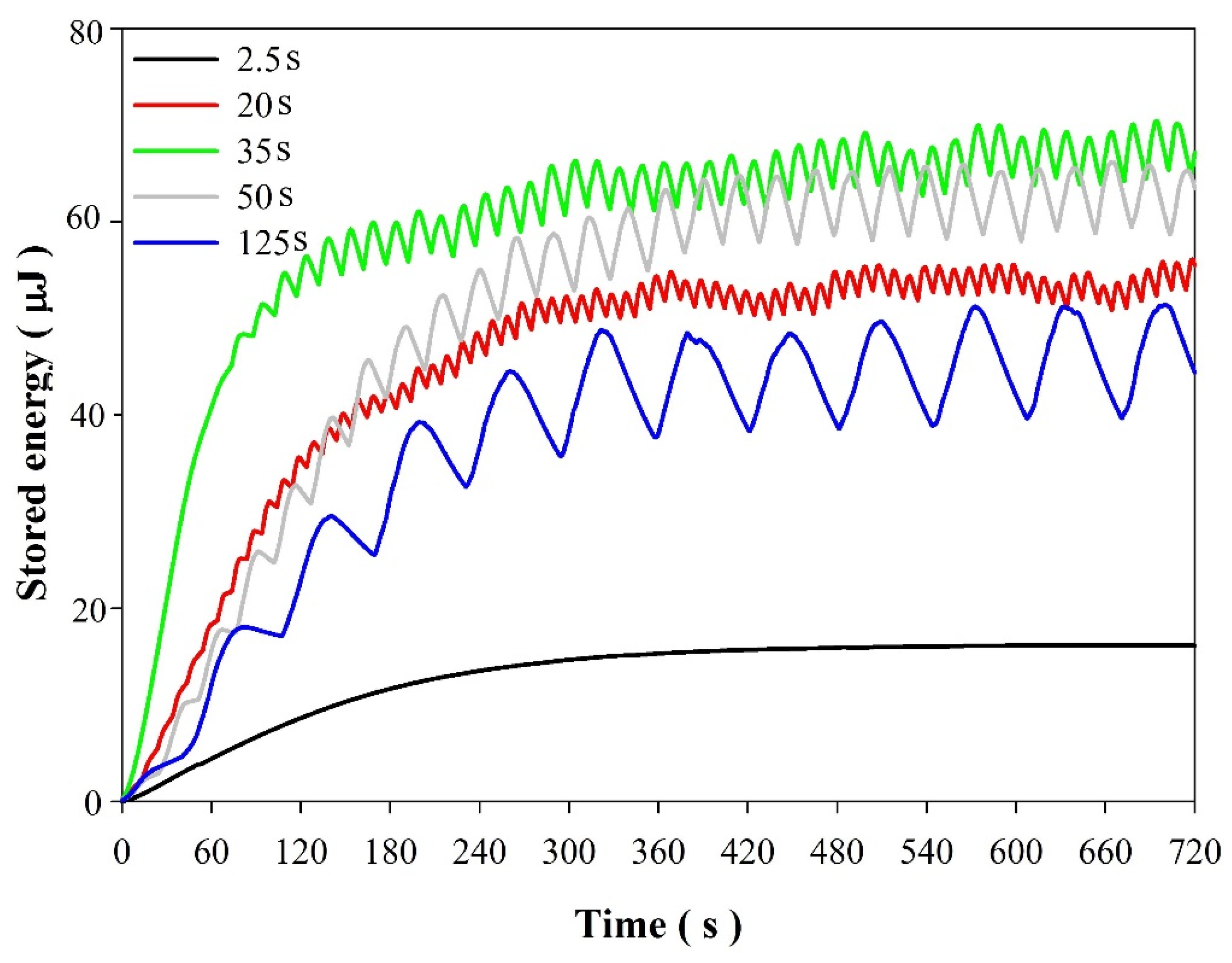
Figure 10 shows the relationship between the stored energy in the 10 μF electrolytic capacitor at the various period times. A longer time was more beneficial when harvesting thermal energy than a shorter time. However, neither the shorter nor longer times allowed for pyroelectric energy to be harvested efficiently. In shorter times, the pyroelectric harvester was weak due to the thermal capacity of the PZT pyroelectric cell. In other words, the PZT pyroelectric cell needed a thermal time constant (τ
T =
H/
GT,
H: Thermal capacity,
GT: Thermal conductance) to harvest sufficient thermal energy. In the longer times, the PZT pyroelectric harvester was also ineffective due to the lower temperature variation rate over the period. The frequency of ripples in the stored energy curves was related to the period of the shutter. The amplitude of ripples in the larger period was larger than that in the smaller period. This could be attributed to an excellent temperature variation rate firmly held over the longer period. The period of 35 s was suitable for the storing of thermal energy of about 70 μJ by using the proposed pyroelectric harvester. This energy could also be stored when using only the disk generator at a speed of about 80 RPM. The optimal period of 35 s in the pyroelectric harvester was with the disk generator at a rotary velocity of about 31 RPM, a wind speed of about 1 m/s and the planetary gear system having a speed reduction ratio of 1:36. This optimal situation occurred in the weaker wind power. However, the stored energy of the disk generator was about 40 μJ, while the rotary velocity of the disk generator was about 31 RPM. In this state, the stored energy acquired from the pyroelectric harvester was about 75% more than that from the disk generator. Hence, the pyroelectric harvester was beneficial in a condition of a light breeze. Moreover, the period of raising and lowering the temperature in the pyroelectric cell was also a critical factor for enhancing the performance of the PZT pyroelectric harvester.
Figure 7.
Relationships between the voltage (a) and current (b) at five different period times (2.5 s, 20 s, 35 s, 50 s and 125 s) for the PZT (Lead Zirconate Titanate) pyroelectric harvester.
Figure 7.
Relationships between the voltage (a) and current (b) at five different period times (2.5 s, 20 s, 35 s, 50 s and 125 s) for the PZT (Lead Zirconate Titanate) pyroelectric harvester.
Figure 8.
Induced current and temperature variation rate over time at five different period times (2.5 s (a); 20 s (b); 35 s (c); 50 s (d); and 125 s (e)) for the PZT pyroelectric harvester.
Figure 8.
Induced current and temperature variation rate over time at five different period times (2.5 s (a); 20 s (b); 35 s (c); 50 s (d); and 125 s (e)) for the PZT pyroelectric harvester.
Figure 9.
Relationships between the induced charge per second (a); and the stored energy per period in the 10 μF electrolytic capacitor (b) at various period times for the PZT pyroelectric harvester.
Figure 9.
Relationships between the induced charge per second (a); and the stored energy per period in the 10 μF electrolytic capacitor (b) at various period times for the PZT pyroelectric harvester.
Figure 10.
Relationships between the stored energy in the 10 μF electrolytic capacitor and times of various periods for the PZT pyroelectric harvester with temperature fluctuations in the range from 65 °C to 75 °C.
Figure 10.
Relationships between the stored energy in the 10 μF electrolytic capacitor and times of various periods for the PZT pyroelectric harvester with temperature fluctuations in the range from 65 °C to 75 °C.
Decreasing the radiation power for evaluating the performance of the PZT pyroelectric harvester at a lower temperature fluctuation, the radiating heat lamp with the shutter resulted in temperature fluctuations in the range from 55 °C to 65 °C.
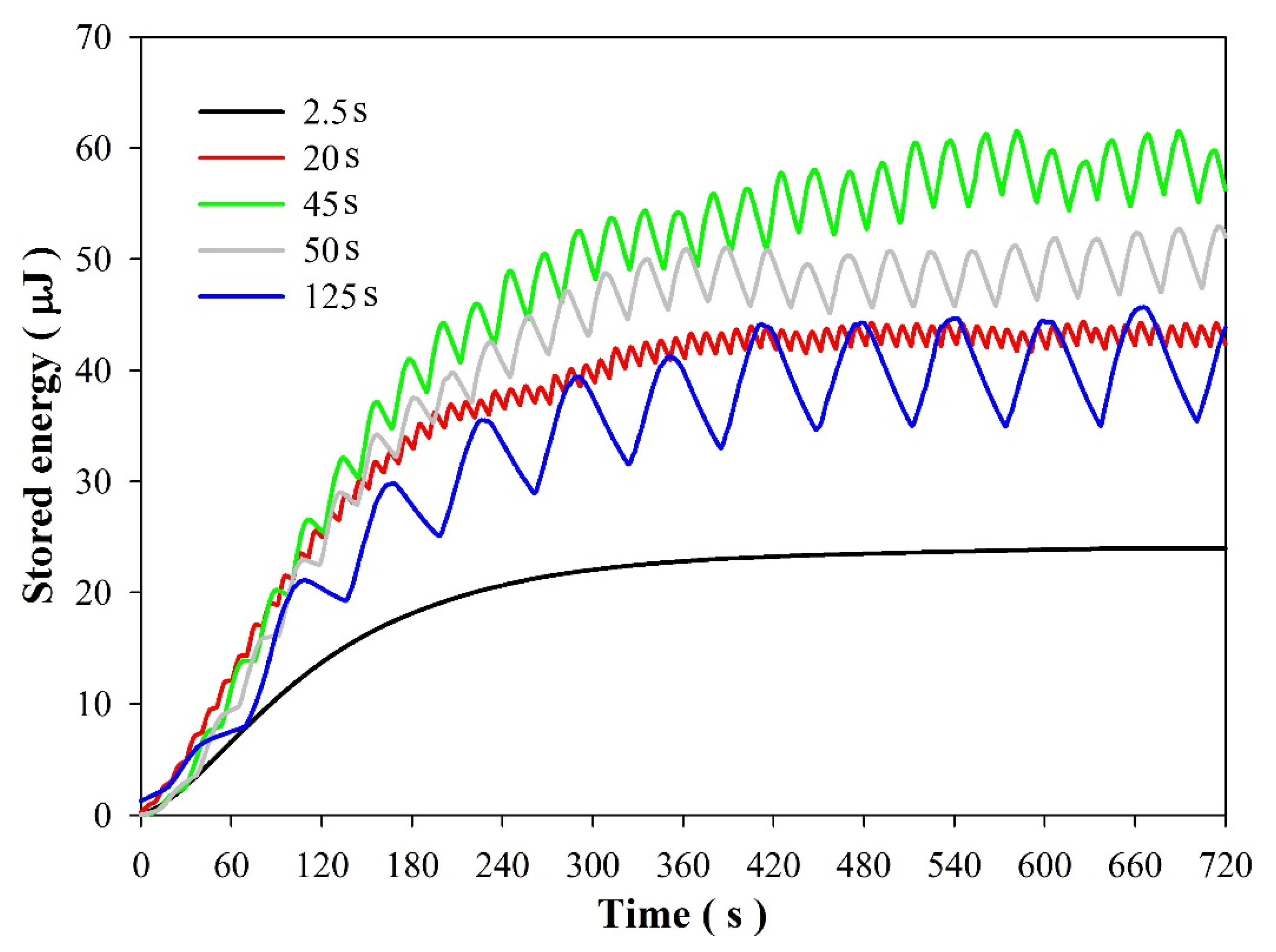
Figure 11 shows the relationship between the stored energy in the 10 μF electrolytic capacitor and times of 2.5 s, 20 s, 45 s, 55 s and 125 s for the PZT pyroelectric harvester. It was obvious that the radiation power with temperature fluctuations decreased, the stored energy was also reduced. Moreover, the optimal period of the PZT pyroelectric harvester also increased to 45 s for harvesting stored energy of about 60 μJ. This could infer that the PZT pyroelectric cell needed more time to absorb the thermal energy when the radiation power was lower. The stored energy rate in the range from 65 °C to 75 °C was apparently higher than that in the range from 55 °C to 65 °C. Hence, while the disk generator was active in a rich wind source, the pyroelectric harvester was active in a meager wind source with plentiful solar radiation. Although the generated energy of the proposed pyroelectric harvester was lower than that of the disk generator, the pyroelectric harvester played a complementary role, in cooperation with the disk generator, in the generating of electrical energy.
Figure 11.
Relationships between the stored energy in the 10 μF electrolytic capacitor and times of various periods for the PZT pyroelectric harvester with temperature fluctuations in the range from 55 °C to 65 °C.
Figure 11.
Relationships between the stored energy in the 10 μF electrolytic capacitor and times of various periods for the PZT pyroelectric harvester with temperature fluctuations in the range from 55 °C to 65 °C.


