1. Introduction
With the increasing demand for passive (energy efficient) houses in moderate-climate countries such as Korea and Japan, more airtight and heat-insulated houses are being developed. In such houses, mechanical ventilation by means of fans and natural ventilation through openings are used to maintain good indoor air quality. However, deterioration of the air and loss of energy occur as a result of increased ventilation load when the ventilation fans are turned off or ventilation channels are not appropriately opened. As an efficient means of solving this problem, passive ventilation involving continuous natural ventilation through the skins of a building has been proposed.
However, for the efficient operation of a solar house, it is important not only to improve the efficiency of energy generation, but also to prevent the loss of energy. Accordingly, a ventilation device is required that satisfies the required ventilation of the solar house while exhibiting no heat loss. It is considered that the use of a passive natural ventilation system and surface-treated exterior walls in a solar house is far more efficient than the adoption of point-to-point mechanical ventilation. Such a design not only continuously affords the required minimum ventilation rate, but can also better deal with an increase in the ventilation load, which would otherwise degrade the indoor thermal environment. Along this line, Hoyano
et al. [
1] proposed the use of “breathing architectural members” (BAMs) with natural ventilation functions as a surface treatment for the exterior walls and ceilings of a passive solar house in warm-climate areas such as Tokyo. This also enables control of the flow of heat, air, and moisture.
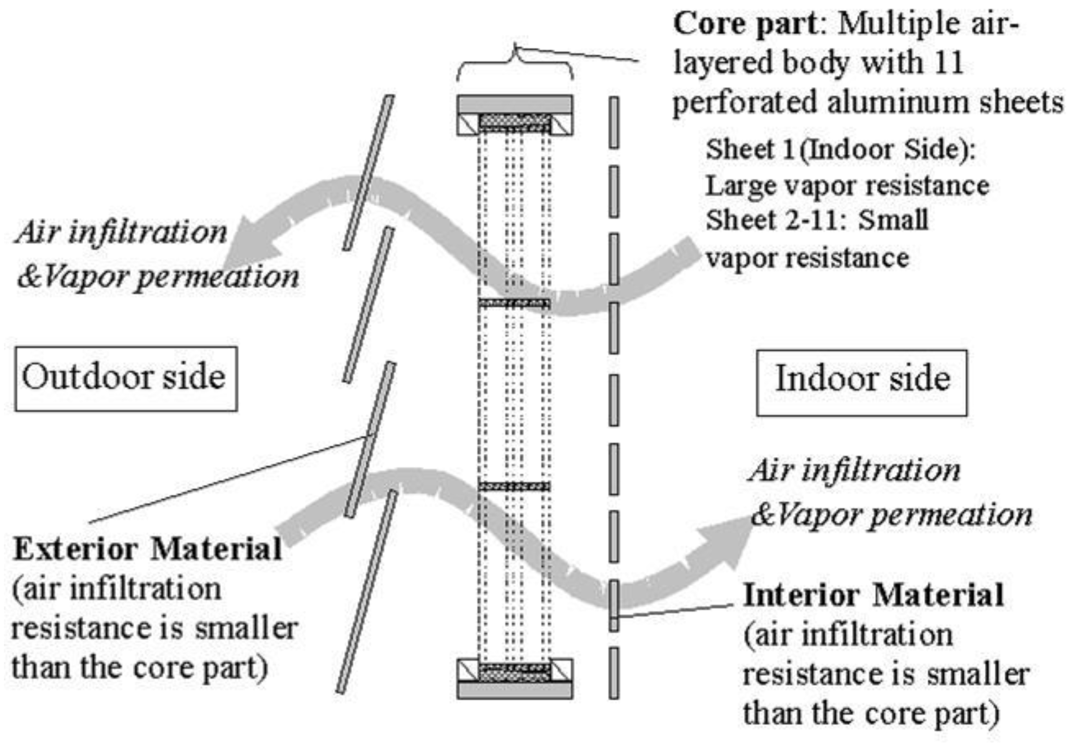
A BAM includes internal and external materials with ventilation resistances lower than that of the core part, which consists of a multi-layered air body made from porous aluminium sheets, as shown in
Figure 1. The member allows air to flow between the indoor and outdoor sides through its entire surface under the effect of the differing indoor and outdoor temperatures or external wind pressure. This ensures that the required ventilation performance is maintained. In addition, the vapour that flows through the BAM is rapidly discharged by air movement, thereby avoiding damage resulting from internal condensation. Although some studies have been conducted on ventilation through building skins, such as those of Dimoudi
et al. [
2], Imbabi
et al. [
3], and Stavridou
et al. [
4], Biserni
et al. [
5], the present study was unique in that the employed BAM did not require the driving force of a mechanical fan, but only natural wind pressure and temperature difference. Based on analysis of meteorological data, internal condensation during the period that the air flowed through the member was prevented by the use of porous aluminium sheets with different opening ratios. The efficiency of the heat exchange inside the member was also maximized by using multiple layers of the aluminium sheets.
Hoyano
et al. [
1,
6] proposed the use of a one-dimensional prediction method to adapt a BAM to a warm-climate area with regard to the movement of air, heat, and water vapour. Yoon
et al. [
7] performed experiments under weather conditions representative of a warm-climate area. The results were used to verify achievement of the target ventilation performances, insulation, and water vapour movement. It was found that, when a BAM was applied to a passive solar house, it could be considered as a passive architectural member under stable conditions. However, this is limited to the case of using a single member, and the evaluation of ventilation performance and energy-saving effect of a BAM in a real full-scale house was left to further study.
In the present study, we comprehensively evaluated the performance of BAMs when applied to the ceiling and outer walls of a passive house. BAM samples were fabricated for use in one-dimensional chamber experiments. Numerical models for evaluating the removed heat and air movement were developed and verified by comparing their predictions with experimental results. The effectiveness of the BAMs was confirmed by numerical simulation using the air and heat movement prediction method and the ventilation calculation method. The present study was a follow-up to that of Yoon and Hoyano [
7]; however, despite their methodological similarities, the present chamber experiment employed a BAM unit with a casing specifically designed for application to an actual house. In addition, the variation in ventilation depended on the direction of the air flow, which was determined by pressurizing and depressurizing the unit.
2. Numerical Prediction Models for Quantifying Heat and Air Movement
The calculation range of the numerical models for predicting the amounts of heat and air movement by the BAM was set between the indoor-side air layer of the first aluminium sheet and the outdoor-side air layer of the
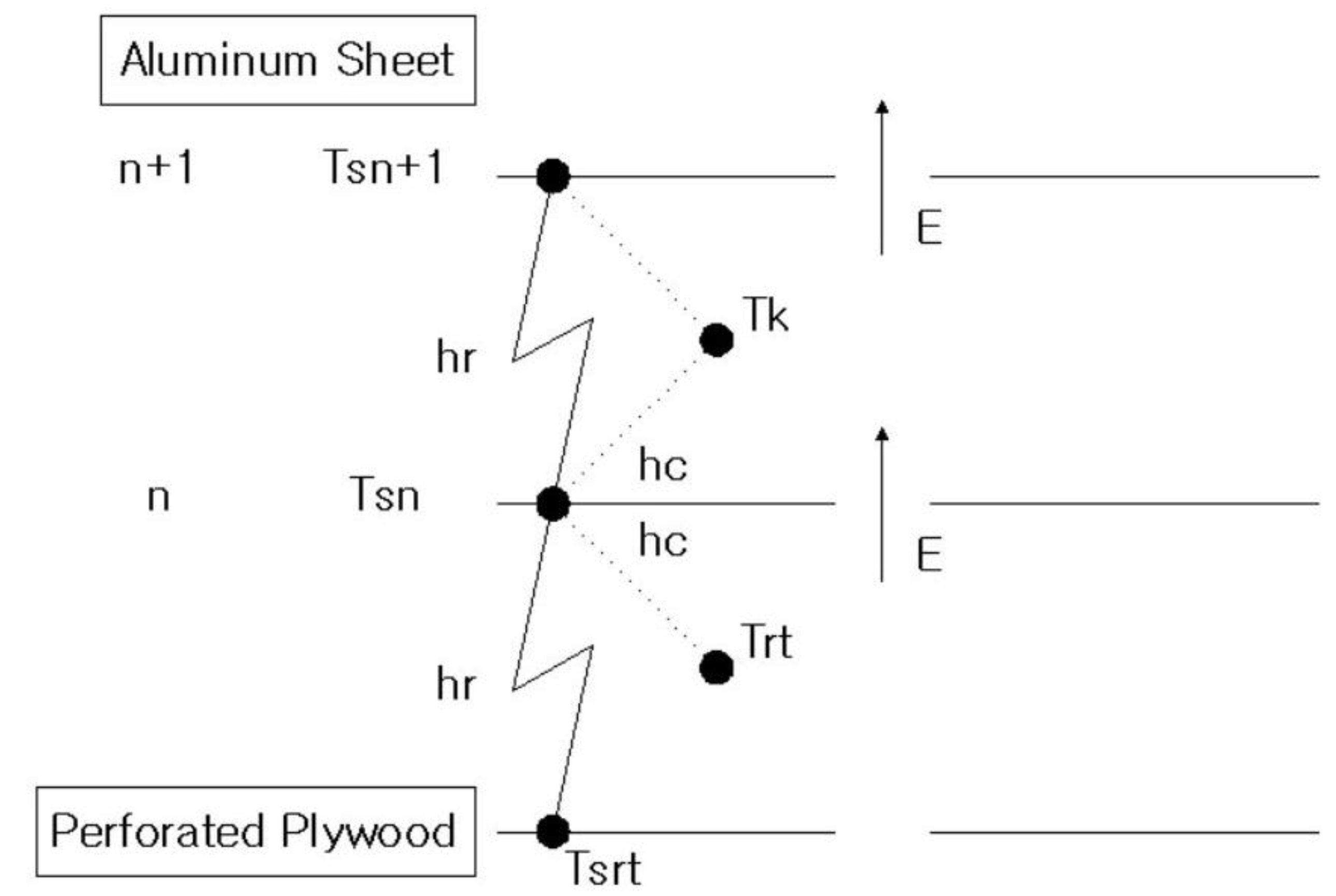
mth aluminium sheet. The boundary conditions were defined by the indoor and outdoor temperatures, the air infiltration direction, and the differential pressure across the member. The calculations were performed in such a way as to simultaneously validate the different components of the heat and air movements like
Figure 2, by taking the following items into consideration based on the findings of a previous study [
1]:
Convective heat transfer by a porous aluminium sheet and its air layer, Ec
Radiant heat transfer through adjacent perforated aluminium sheets, Er
Air infiltration due to differing air pressure across the hole, between two air layers and the movement of heat due to the air infiltration, Ei
The thickness of the aluminium films used to fabricate the core part of the BAM was 25 µm and heat transfer by thermal conduction through the aluminum films could be ignored in the heat calculation for the core part, which also contained air layers.
When predicting the volume of air infiltration, it was assumed that the buoyancy due to the temperature difference across the air layer could be ignored, but not the pressure difference between the indoor and outdoor sides of the wall. The volume of air infiltration,
V [m
3/ (m
2s)], through the wall is given by:
where:
where:
c: Flow coefficient [–] [
8]
A: Opening area per unit area [m2/m2]
γ: Air density(=1.293×273.15/T[K][kg/m3)
P: Air pressure [Pa]
r: Indoor
o: Outdoor
m: Number of aluminium films
Heat movement is quantified as follows:
- (1)
The convective heat transfer rate from the surface of an aluminium sheet,
hc [W/m
2°C], is determined using the following equations of the Nusselt number
Nu and by convective heat transfer (The Nusselt number was determined with reference to [
9]. The convective heat transfers of fully developed laminar flows through pipes with different cross sections are defined in this work, and Nu = 7.54 was adopted as the appropriate value for the present study).
- (2)
The radiant heat transfer rate,
hr [W/m
2°C], between the surfaces of adjacent aluminium sheets is determined by the following equation :
However:
- (3)
The heat movement,
Ei [W/m
2], that accompanies the air infiltration can be determined using the following equation (The formula used to calculate the heat transfer accompanying air permeance E[W/m
2°C] is similar to the method for determining ventilation load presented in [
10]):
where:
Nu: Nusselt number
d: Equivalent diameter of pipe section [m]
λ: Thermal conductivity of air [W/(mK)]
D: Thickness of air layer [m]
εn: Emissivity of aluminium sheet, n [–]
Tsn: Surface temperature of aluminium sheet, n [°C]
σ: Stefan-Boltzmann constant(=5.67x10⁻⁸) [W/(m2K)]
Cp: Specific heat at constant pressure [J/(kg°C)]
Tk: Temperature of air layer, k [°C]
3. Heat and Air Infiltration Experiment
3.1. Outline of the Experiment
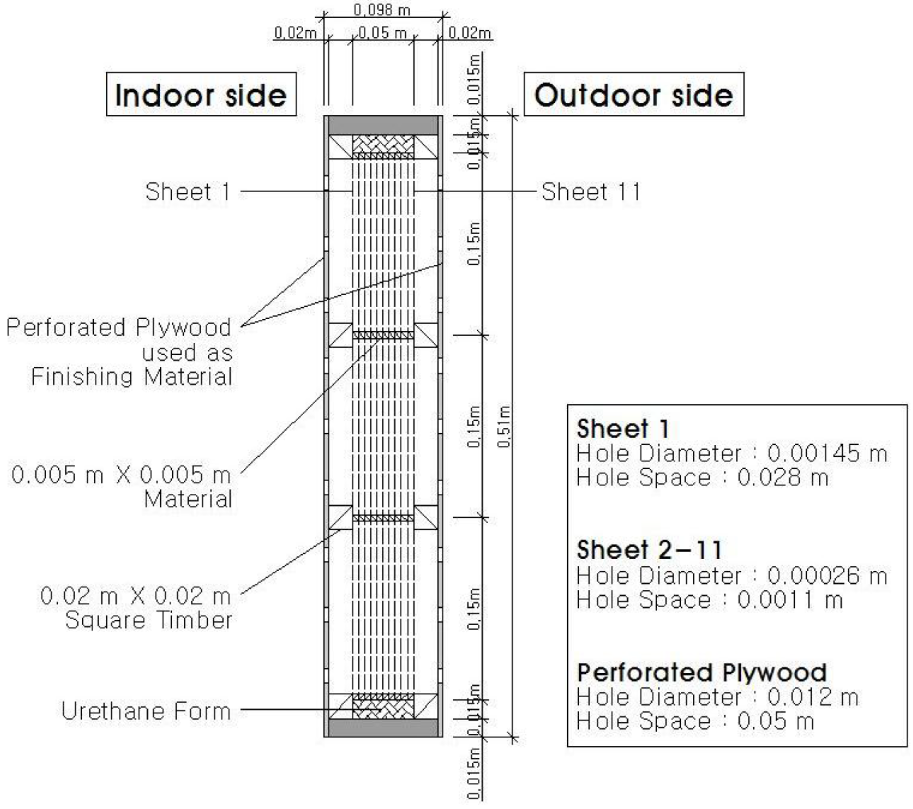
The core part of each BAM sample consisted of 11 porous aluminium sheets, each of which had a low emissivity of 0.1 or less on both sides, and 0.005 m air layers on the core material, which was woven to 0.15 × 0.15 m (see
Figure 3). The average hole diameter and hole spacing of the porous aluminium sheets were set to 0.00145 and 0.028 m, respectively, for sheet No. 1 from the indoor side, and 0.00026 and 0.0011 m for sheets 2–11. This was based on the usual values used for BAMs under normal conditions in a warm-climate [
1].
The BAM samples were made from polyethylene plywood sheets, which were installed in the experimental house as finishing materials. A space of 0.015 m was left between the mould of the wooden case and the BAM, and was filled with water-blown urethane foam so that the flow through the member could be considered a one-dimensional laminar flow.
With regard to the specifications of the porous polyethylene plywood used as the finishing material, the hole diameter was set to 0.012 m, the hole spacing to 0.05 m, and the opening rate to 4.5%. Generally, the finished structure of a BAM affects the air permeability of the member, and hence the thermal insulation and vapour permeation. In the samples employed in the present study, however, the finishing materials had an extremely low air permeance resistance compared to the core part, and therefore did not affect the overall air permeance and heat insulation performance of the members. Hence, in the following discussion of the air permeance and heat insulation performance of the members, sheets numbered 1 to 11 are considered to determine the air infiltration and thermal insulation performances of the BAM. The temperature of the air in the 0.02 m air layer formed on the indoor side is also regarded as the actual temperature of the air flowing inwards.
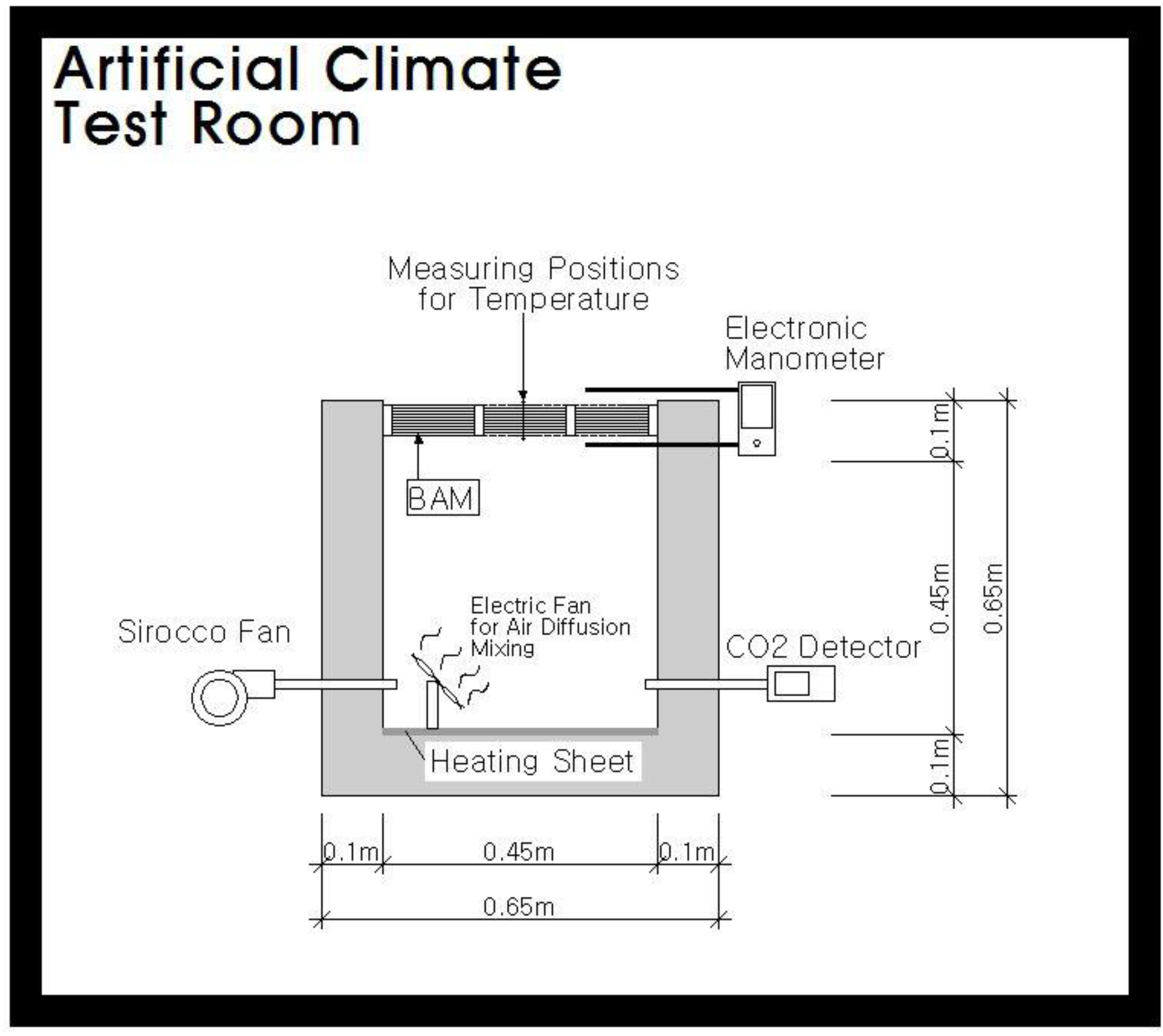
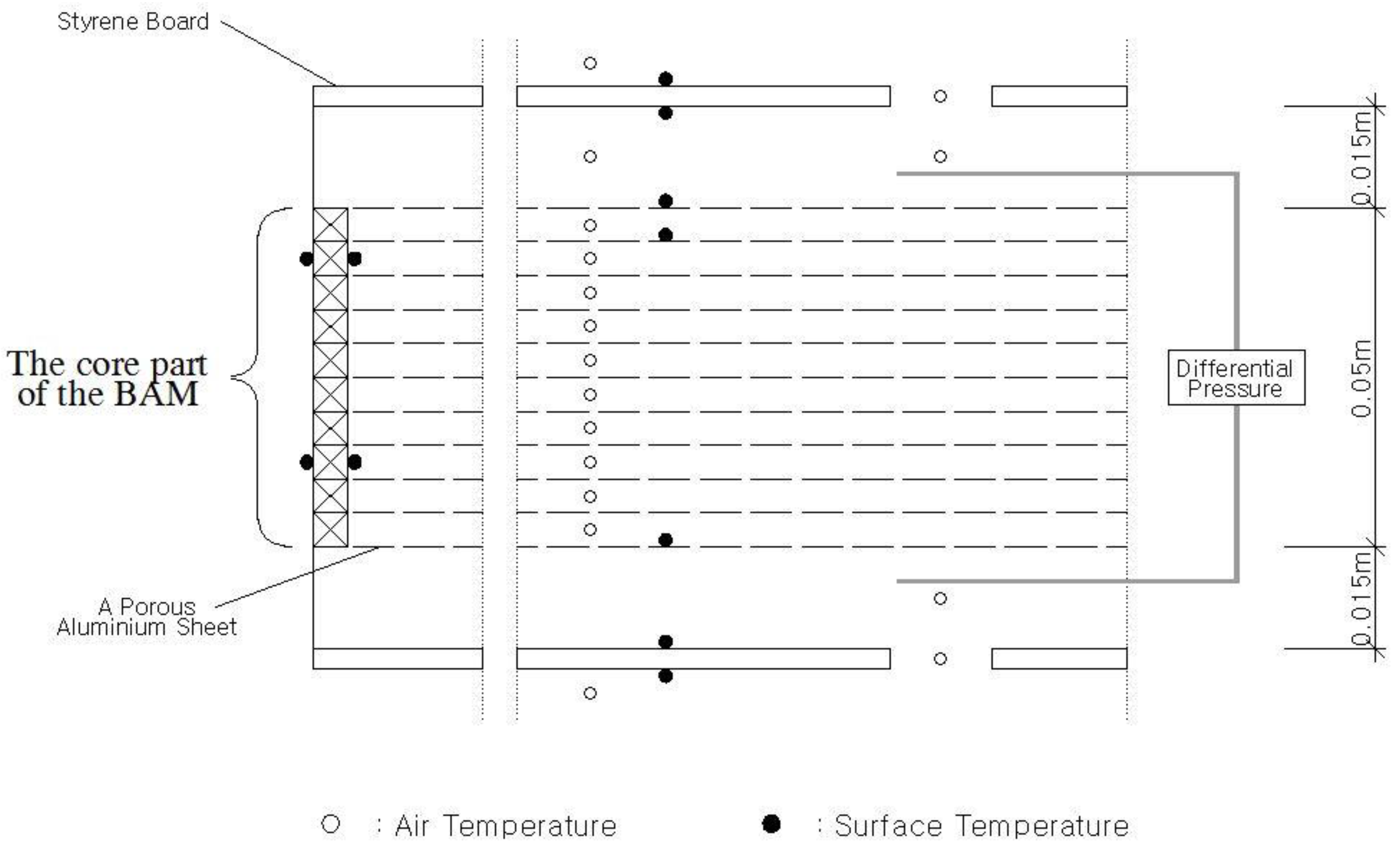
Figure 4 shows the experimental setup, which was conducted in an artificial climate test room in which the relative temperature of outdoor air was automatically maintained within ±1 °C of the target value. Conversely, the relative temperature of the indoor air was manually controlled by means of an electric heating sheet and a portable electric fan, which provided a sufficient volume of mixed air. The BAM (0.445 × 0.45 × 0.09 m) was covered with polystyrene boards to make it airtight and achieve excellent insulation, after which it was installed in the chamber. The internal structure of the BAM between the 0.004 m-thick porous polystyrene panels (hole diameter = 0.012 m, hole spacing = 0.05 m) on the indoor and outdoor sides consisted of 11 layers, which included porous PET-AL sheets and a layer of wooden grids spaced at 0.005 m. The sheets on either side of the grid were covered with waterproof paint and sandwiched between PET-AL sheets. In addition, a polystyrene panel with 0.015 m air layer was placed on either side of the BAM.
In the experiment, a T-type thermocouple was used for temperature measurement. A differential pressure gauge (TESTO 512, Testo, Lenzkirch, Germany) and multi-gas analyser (RAE System, MultiRAE IR, San Jose, CA, USA) were also employed. The performance and specifications of the measuring instruments were as presented in
Table 1 and
Table 2.
3.2. Experimental Conditions and Methodology
The outdoor air temperature was set to 5 °C, based on outdoor night-time temperature in the Tokyo area during winter. The temperature of the air inside the house was set to 25 °C by floor heating under normal conditions. If a passive solar house is operated under these conditions, there would be significant fluctuation of room temperature. In the present study, however, only the wind pressure was considered a variable, while room temperature was considered constant.
To apply a constant air pressure to the ceiling, the external air pressure was reproduced by blowing the air (pressurization) and allowing it to expel (decompression) through the blower that formed part of the experimental setup. To evaluate the effect of external air pressure, room temperature was regulated by the floor heating. The conditions were coordinated to allow air to flow into the room, the temperature of which was set to 25 °C, with the heat source controlled to 134 W/m2 (floor surface temperature = 26.5 °C) under normal conditions.
The volume of air infiltration under constant air pressure was determined experimentally by means of the tracer method using carbon dioxide (CO2) traced gas. The pressure applied to the sample was gradually varied within 0–10 Pa by means of a pressurization and decompression device.
The main measurement items were the following of air infiltration and the temperature distribution within the member. The measurement parts and items are as shown in
Figure 5.
3.3. Experimental Results
3.3.1. Air Infiltration Characteristics under Constant Pressurization
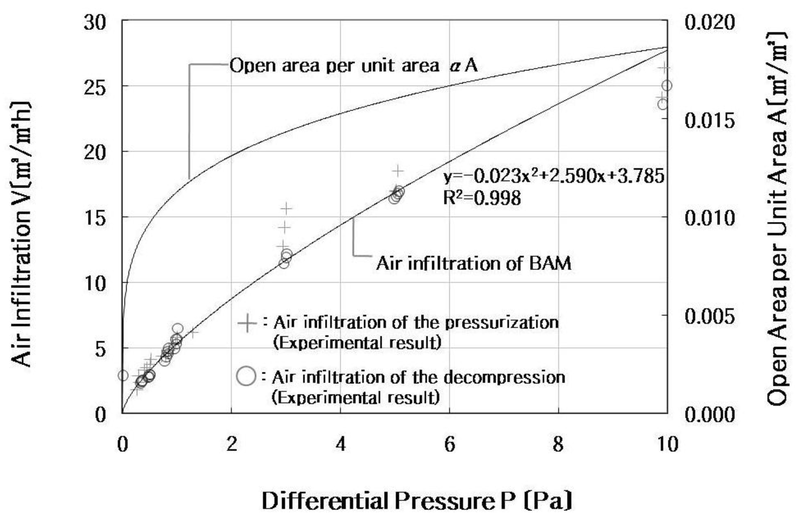
Figure 6 compares the measured and calculated (Equation (1)) volumes of air infiltration.
The modeled and experimental results are in better agreement up to 5 Pa under decompression conditions, while the deviations range between 0.4% and 33.5% at more than 3 Pa during pressurization. This observation can be attributed to the variation of the shape loss resistance of the sheet holes with the perforation direction of the aluminium sheet.
3.3.2. Temperature Increase in Inflow Air
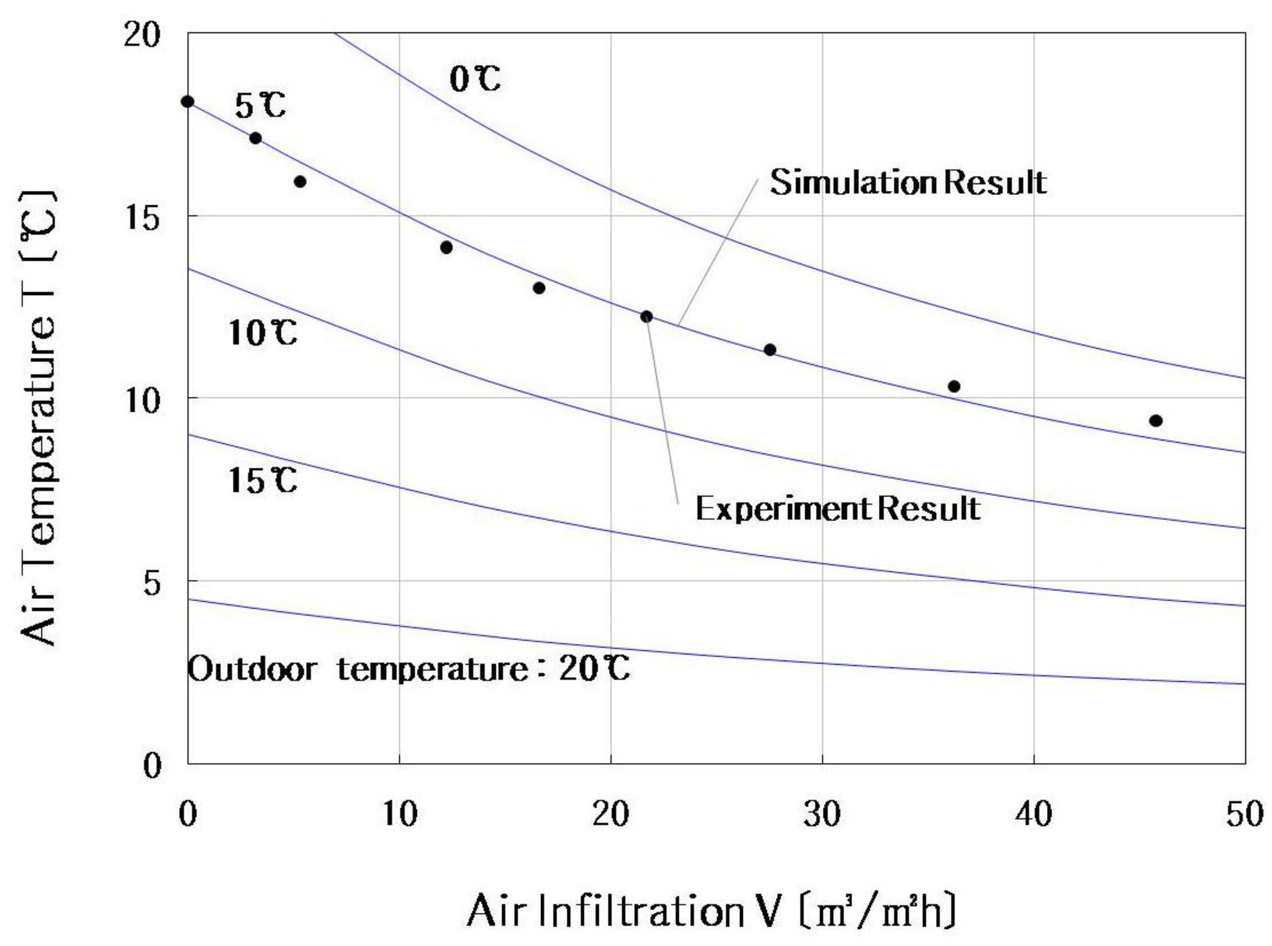
Figure 7 shows the temperature variation of the outside air flowing into the room under constant air permeation. For air permeations within 3–46 m
3/ (m
2h) under the conditions set for outside air (temperature = 5 °C, which is the design condition of the member), the temperature of outside air flowing into the room varied between 8.1 and 18.1 °C. Although the experimental values indicated in
Figure 7 differ somewhat from those of a previous study (Yoon and Hoyano [
7]) due to the casing of the core part of the BAM in the present study, they remain largely comparable. The differences between the modeled and experimentally measured temperatures are within 0.5 °C and dependent on the amount of air infiltration. This could be due to subtle changes in the pressure and temperature conditions of the chamber. However, the differences between the measured and calculated values in the present study are within 5%, which thus validates the proposed numerical models for predicting heat and air transfer.
3.3.3. Equivalent Heat Transfer Coefficient (U-value)
The most universal indicator of the insulation performance of a member is the heat transfer coefficient. In the particular case of a BAM, as air passes through the member and heat flow occurs, the equivalent heat transfer coefficient can be used to assess insulation performance in the manner employed by Taylor and Imbabi [
11,
12] in their study of dynamic insulation. The formula for calculating the equivalent heat transfer coefficient (U-value) is as follows:
where:
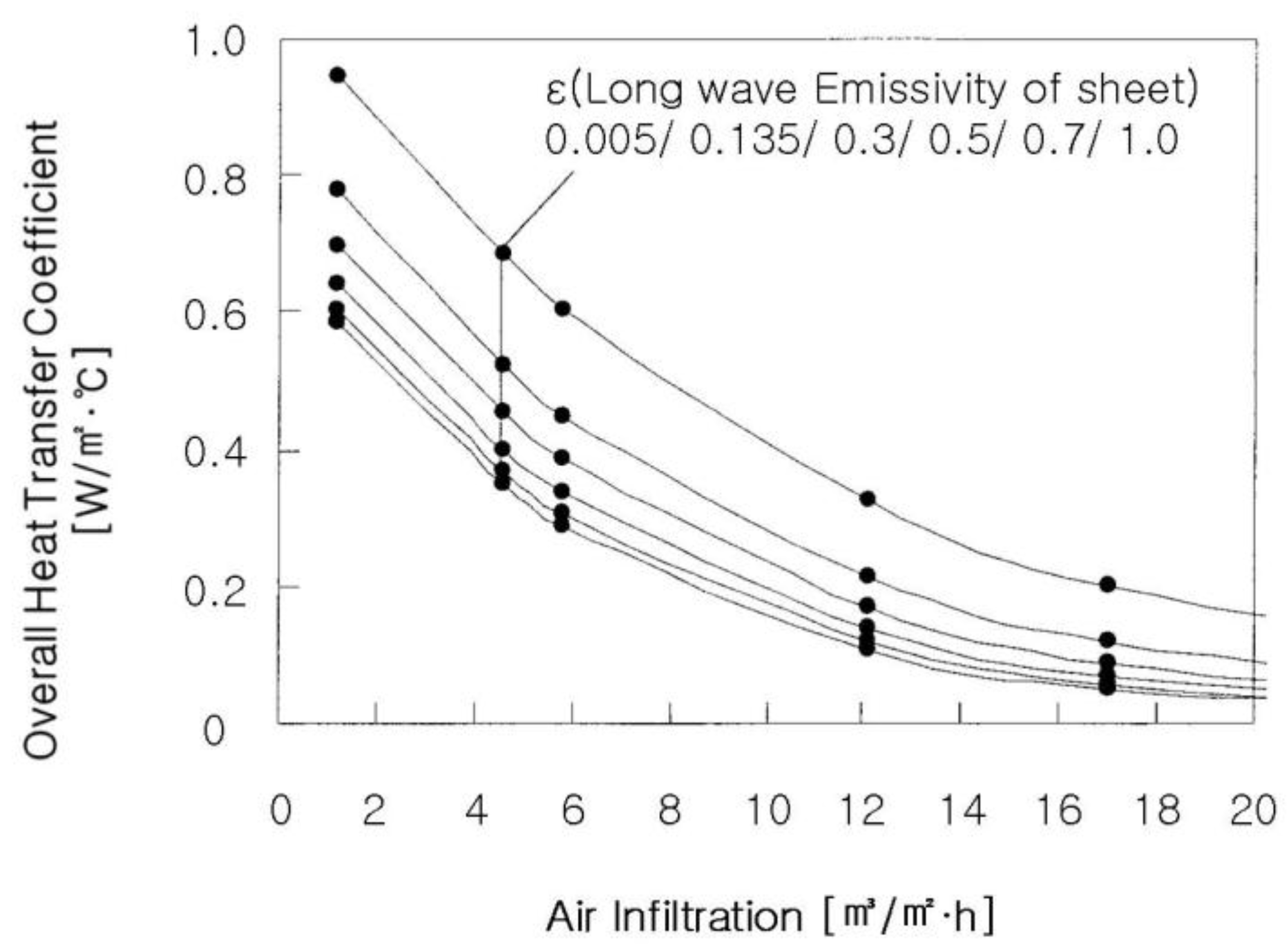
Figure 8 shows the calculated equivalent heat transfer coefficient. As can be observed, the coefficient varies significantly with varying low air infiltration rate, but tends to stabilize with increasing air infiltration rate. The emissivity of the aluminium sheets of the BAM sample was 0.135, for which the equivalent heat transfer coefficient was determined to vary between 0.069 and 0.601 W/ (m
2°C) when the air infiltration rate varied between 1.3 and 17.0 m
3/(m
2h). The emissivity of the aluminium sheets of the BAM was measured by a simplified emissivity test using an infrared radio meter (Dai Nippon Printing Co., Tokyo, Japan).
5. Conclusions
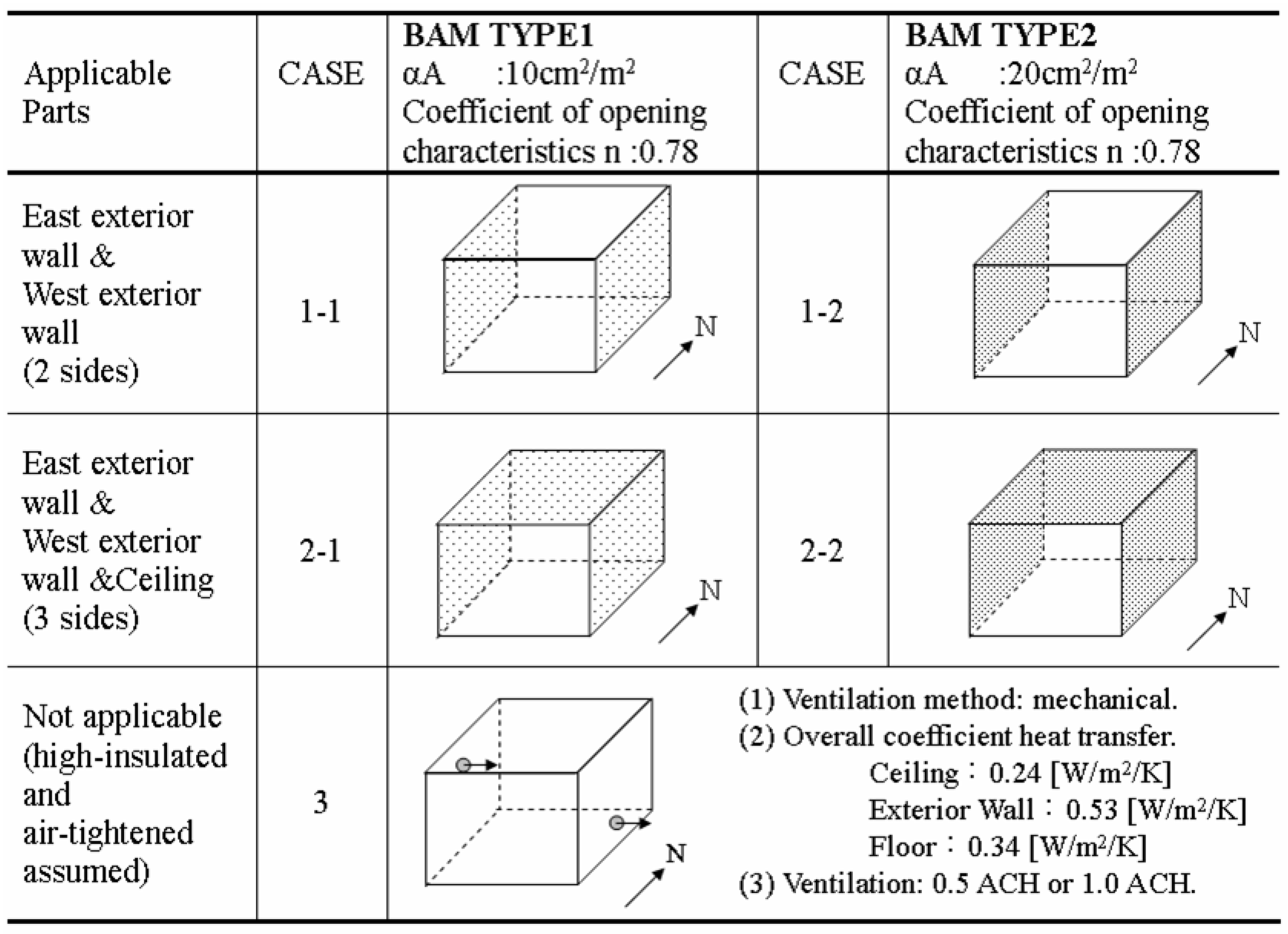
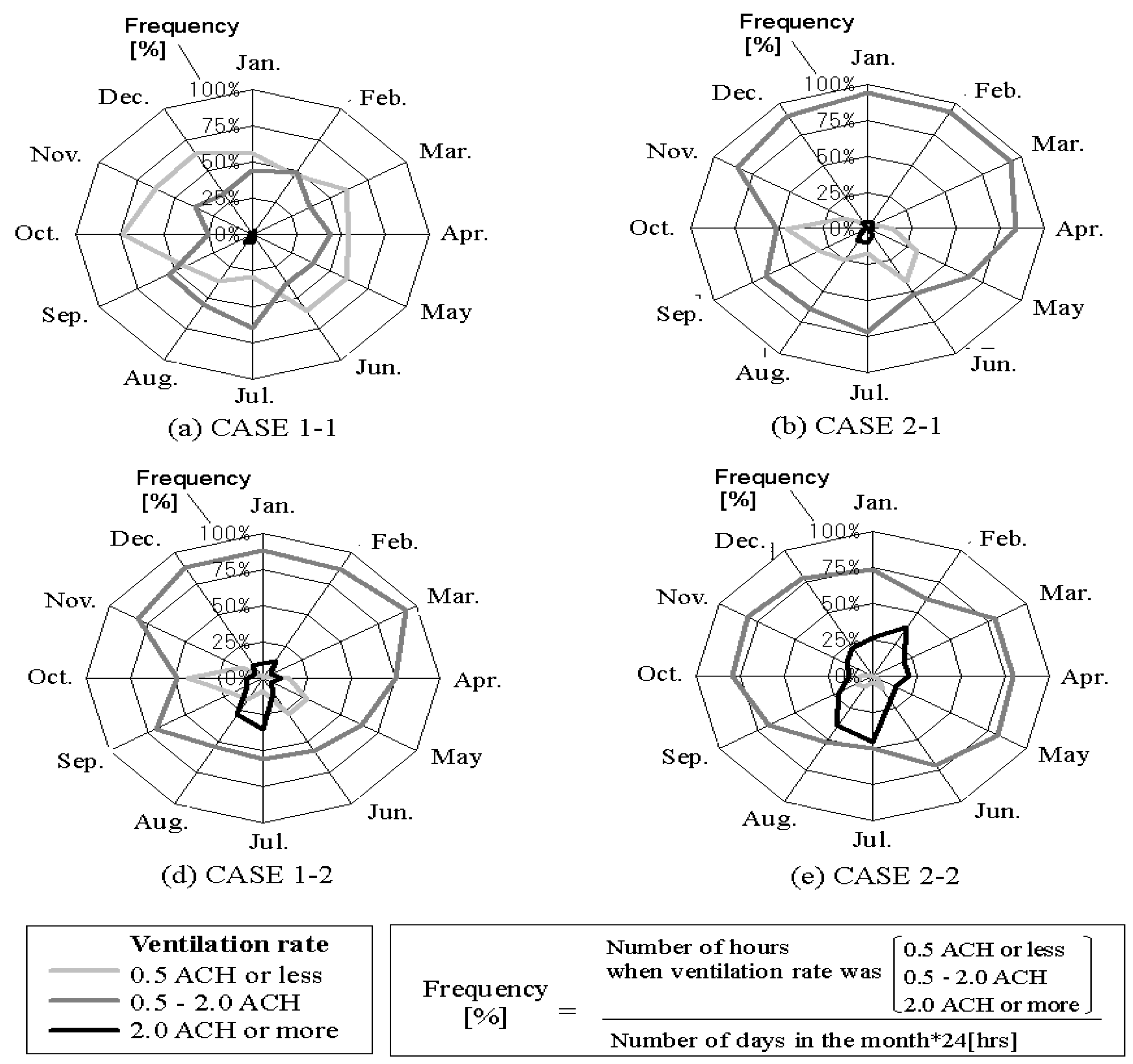
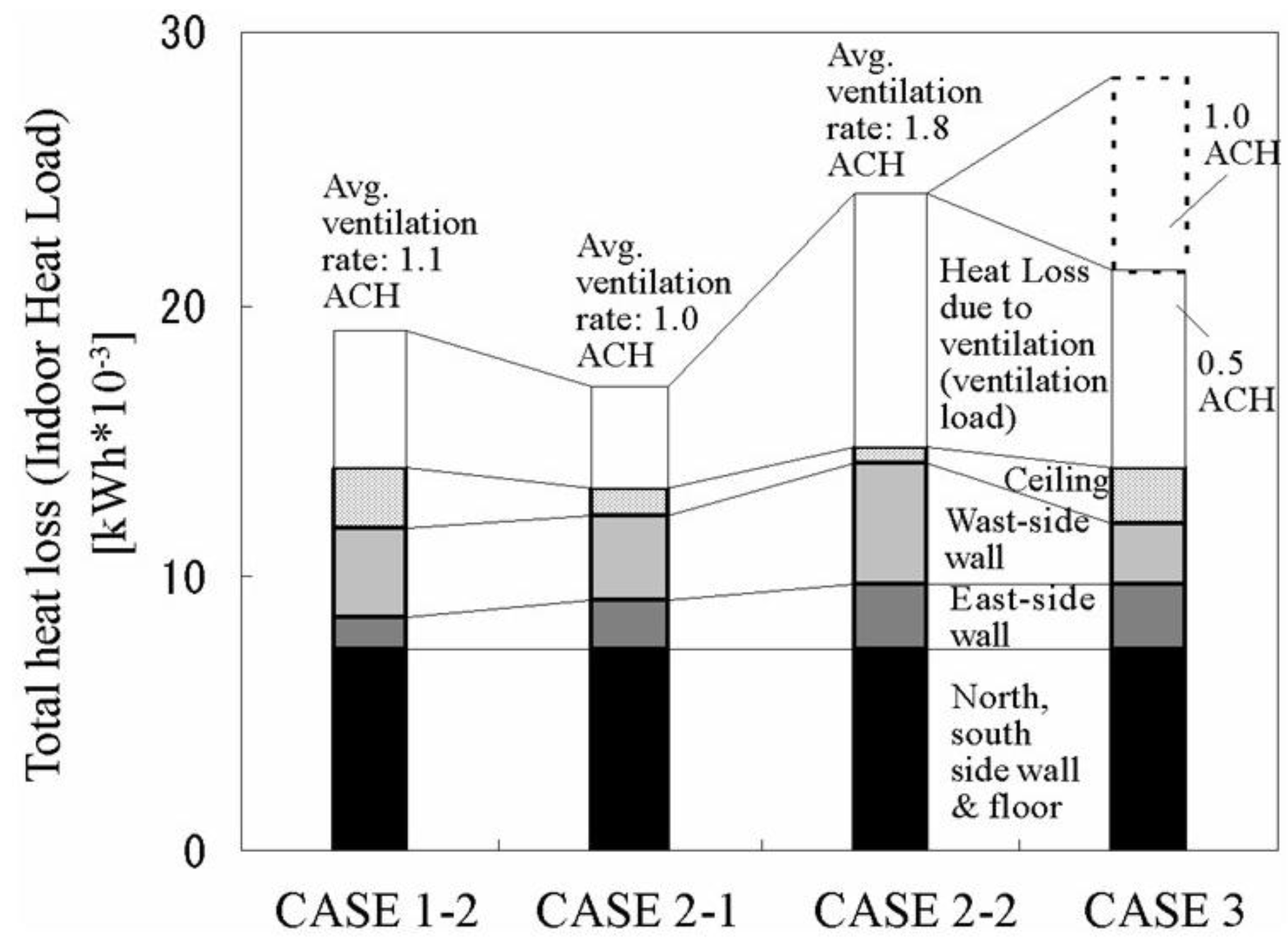
In this study, chamber experiments and numerical simulations of natural ventilation and heat loss, were performed to verify the performance of BAMs applied to houses in a warm-climate area. The numerical models used to predict the heat and air movements were also verified by comparing by comparison with a one-dimensional chamber experiment, which revealed a difference of within 5% in the temperature of the air flowing into the room from outside. Case studies were conducted using BAMs with two different specifications, installed in the ceilings and exterior walls of model houses in the Tokyo area. This was done to confirm the annual ventilation performance and energy-saving effects of the members. In the cases of BAMs with αA = 20 cm2/m2 installed in two exterior walls and the ceilings, the annual required ventilation rate of ≥0.5 ACH was consistently achieved. In addition, heat loss was reduced by 15.3%–40.2% depending on the BAM installation position and the area difference compared to a house with general insulation and mechanical ventilation.


