
A Vision-Based Detection and Spatial Localization Scheme for Forest Fire Inspection from UAV


1
College of Information Science and Technology, Nanjing Forestry University, Nanjing 210037, China
2
Department of Computing and Software, McMaster University, Hamilton, ON L8S 4L8, Canada
*
Author to whom correspondence should be addressed.
Forests 2022, 13(3), 383; https://0-doi-org.brum.beds.ac.uk/10.3390/f13030383
Submission received: 28 January 2022
/
Revised: 14 February 2022
/
Accepted: 24 February 2022
/
Published: 25 February 2022
(This article belongs to the Section Forest Inventory, Modeling and Remote Sensing)
Abstract
:Forest fires have the characteristics of strong unpredictability and extreme destruction. Hence, it is difficult to carry out effective prevention and control. Once the fire spreads, devastating damage will be caused to natural resources and the ecological environment. In order to detect early forest fires in real-time and provide firefighting assistance, we propose a vision-based detection and spatial localization scheme and develop a system carried on the unmanned aerial vehicle (UAV) with an OAK-D camera. During the high incidence of forest fires, UAVs equipped with our system are deployed to patrol the forest. Our scheme includes two key aspects. First, the lightweight model, NanoDet, is applied as a detector to identify and locate fires in the vision field. Techniques such as the cosine learning rate strategy and data augmentations are employed to further enhance mean average precision (mAP). After capturing 2D images with fires from the detector, the binocular stereo vision is applied to calculate the depth map, where the HSV-Mask filter and non-zero mean method are proposed to eliminate the interference values when calculating the depth of the fire area. Second, to get the latitude, longitude, and altitude (LLA) coordinates of the fire area, coordinate frame conversion is used along with data from the GPS module and inertial measurement unit (IMU) module. As a result, we experiment with simulated fire in a forest area to test the effectiveness of this system. The results show that 89.34% of the suspicious frames with flame targets are detected and the localization error of latitude and longitude is in the order of 10−5 degrees; this demonstrates that the system meets our precision requirements and is sufficient for forest fire inspection.
1. Introduction
Forests are the most precious natural resources that the earth gives to human beings. They can provide forest products, protect the environment, regulate climate, purify the air, keep dust, and so on [1]. However, due to the occurrence of forest fires, an uncountable number of people die [2], and millions of hectares of forest lands are burned annually [3], which has caused tremendous damage to the social economy and the ecological environment. In addition, with the characteristics of sudden occurrence and quick spread, forest fires are challenging to control. Hence, the detection and monitoring of early forest fires are essential, and the obtained fire information can support subsequent fire-fighting tasks.
In the past ten years, forest fire detection has mainly adopted manual inspection, watchtower monitoring [4], and ground sensor monitoring [5,6]. However, these methods face problems such as poor flexibility, limited monitoring distance, high costs, and environmental interference. These factors make it difficult to conduct practical forest fire inspections in real-time. With the development of science and technology, the vision monitoring scheme with UAV has become a new trend [7]. The forest monitoring center takes the local forest fire risk level as the basis of patrol, reflecting the flexibility, mobility, and efficiency of UAV inspection.
Traditional forest fire recognition algorithm depends heavily on man-made flame characteristics, such as color, texture, shape, spatial relationship, and temporal relationship. Ryu et al. [8] used HSV color conversion and Harris corner detection in the image pre-processing step. They extracted the corner point facing the upper direction nearby as a region of interest (ROI). Afterwards, a classifier was applied to judge if there is a fire or non-fire to achieve low-false detection. Borges et al. [9] analyzed the frame-to-frame changes of specific low-level features describing potential fire regions, including color, area size, and surface coarseness. Then, fire recognition would be realized according to the Bayesian classifier. Yuan et al. [10] used a method based on color characteristics to detect forest fires and carried on the UAV for patrol. However, there are many missed and false detection cases due to the interference under the circumstances of complex and changeable forest scenes. In recent years, convolutional neural networks (CNN) have been widely used in the image field [11]. Unlike traditional manual feature extraction methods, CNN can automatically learn features through convolution operation with more robust generalization performance and higher recognition accuracy, and were used widely in forest fire detection. For example, Barmpoutis et al. [12] used Faster R-CNN combined with Grassmannian manifold to achieve high recognition accuracy. This method projects candidate fire regions obtained from Faster R-CNN to a Grassmannian space and then aggregates the Grassmannian points based on a locality criterion on the manifold. Lu et al. [13] proposed a two-stream convolutional neural network (TSCNN)for flame region detection. The input of TSCNN consists of two parts: the input image, and the difference image of the two frames, which integrates the static spatial feature and the dynamic temporal feature. Xu et al. [14] ensembled two individual learners, Yolov5 and EfficientDet, to obtain the prediction bounding box to avoid missed detection, then using another individual classifier to determine if these bounding boxes are predicted correctly. Li et al. [15] proposed a forest fire detection algorithm based on Faster-RCNN, R-FCN, SSD, and Yolov3. After comparison, it was found that the recognition accuracy of the algorithm based on Yolov3 reached 83.7%, which is much higher than other algorithms and met the requirements of practical detection.
The algorithms above perform well on accuracy with high-performance computing platforms. However, the edge computing device mounted on the UAV is limited in resources and power consumption, making it hard to deploy large algorithms. Therefore, it needs to use a lightweight and efficient algorithm to realize real-time detection and early warning. Usually, we can only get the position of the fire area on a 2D image from the UAV perspective, and it is difficult for firefighters to find the fire site accurately and quickly on the ground. In order to provide a 3D position of the fire area accurately, the UAV will be equipped with a binocular stereo vision system. According to these, the longitude, latitude, and altitude of the forest fire area will be calculated combined with GPS and attitude data to provide better help for firefighting.
The main contributions of our paper are threefold:
- We propose a visual-based forest fire detection and fire area spatial localization scheme in real-time inspection from UAVs. During the high incidence of forest fires, UAVs equipped with this system are deployed to patrol the forest. When a fire is detected, the controller sends an alarm to the ground control center, along with the longitude and latitude data of fire area, which helps prevent and rescue fires in forests;
- To leverage the advantages of edge computing that bring computation closer to the data source and reduce latency, we deploy a lightweight object detection network (NanoDet) to edge devices. Furthermore, a variety of training tricks are used to further boost precision and execution efficiency;
- We propose a spatial localization method based on a multi-sensor fusion, including an RGB camera, binocular cameras, GPS module, and IMU module. The fire area’s longitude, latitude, and altitude can be acquired through space coordinate transformation.
2. Materials
2.1. Dataset and Annotations
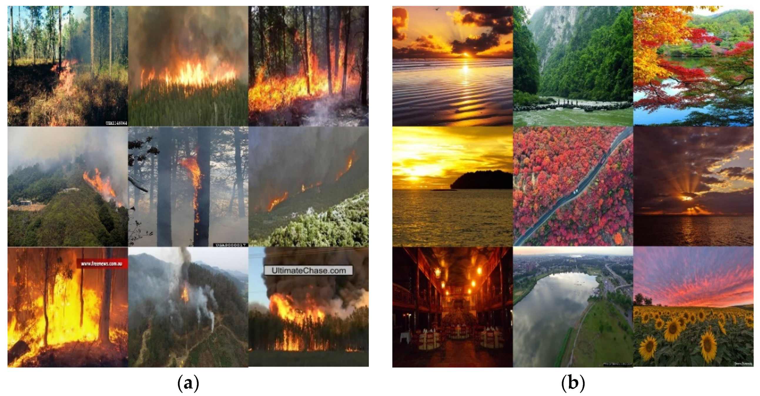
Forest fire detection based on CNN relies heavily on the quality and size of datasets. A high-quality dataset allows a deep learning model to learn more features and have better generalization ability. We collected more than 10,000 images from public fire datasets, such as BowFire [16], FiSmo [17], Firesense [18], VisiFire [19], ForestryImages [20], and 1400 images taken from the perspective of UAVs (Table 1). The dataset consists of forest fire images with different types and scenarios and non-fire images such as forest scene, shadow, sunset glow, red leaves, and so on. Some representative samples are shown in Figure 1.
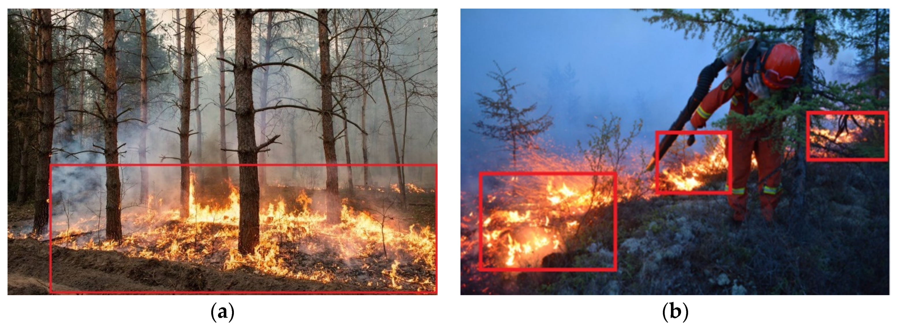
In addition, the annotation of the dataset plays a vital role in model training. Different annotation methods will bring other influences on the model. In this paper, the details of annotation are as follow, and the examples are shown in Figure 2.
- (1)
- Only fire targets are marked. Non-fire and fire-like targets are not marked;
- (2)
- The annotation boundary must be close to the fire target within 2 pixels;
- (3)
- Adopt a large area labeling method for scattered fire targets with very short distances;
- (4)
- Adopt a small area labeling method when there are fire-like targets in a large area.
2.2. Overview of Hardware Device
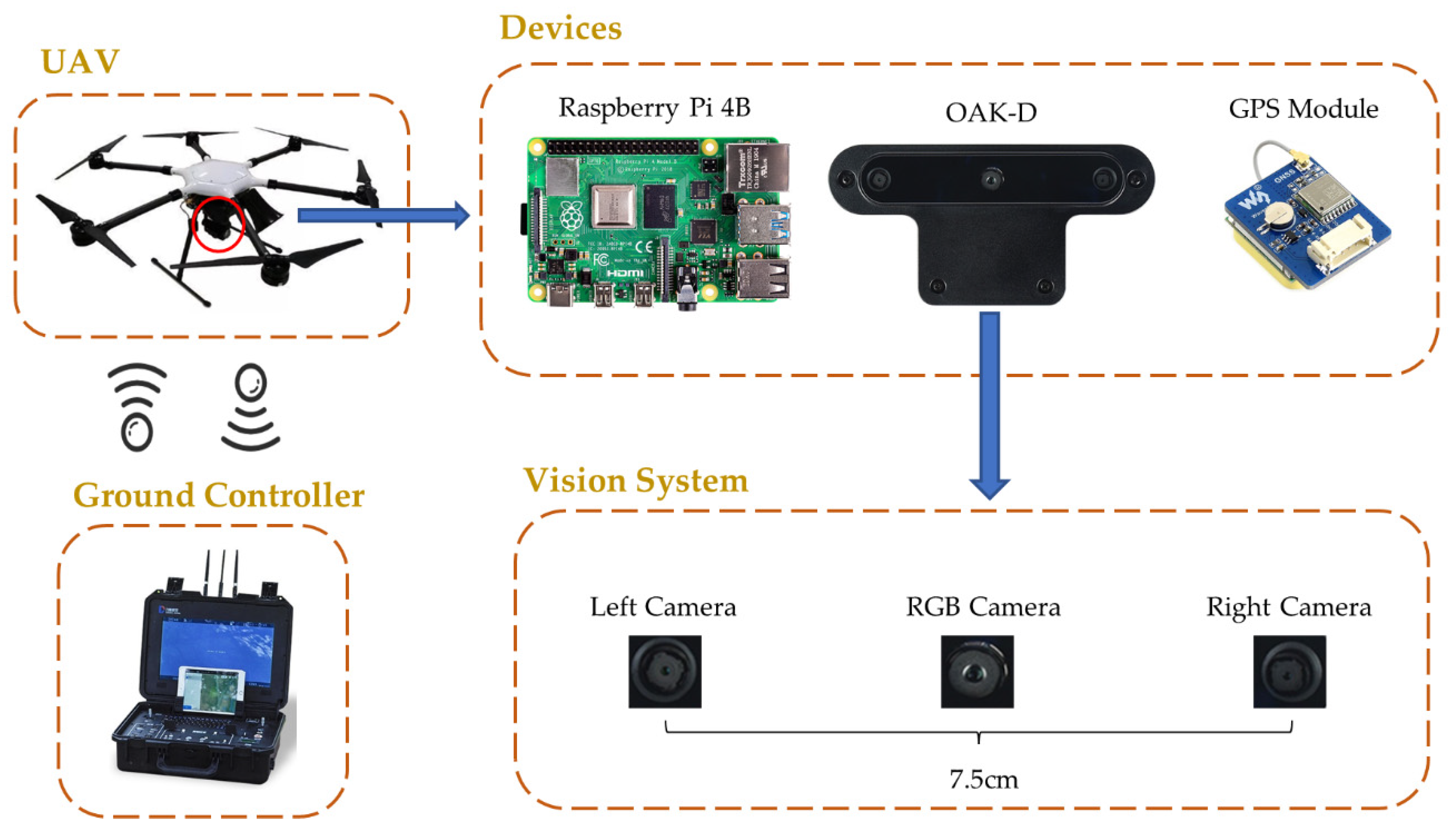
In this paper, a self-developed forest fire detection and fire area spatial localization system is introduced, and Figure 3 shows the hardware system. The whole system consists of a UAV, a Raspberry Pi controller, an OAK-D camera, and a GPS module. The UAV has a maximum load capacity of 5 kg, a maximum flight time of 40 min, and is equipped with a 16,000 mAh battery. The Raspberry Pi acts as the control center, working with the OAK-D camera and GPS module. Its four-core ARM-A73 processor can execute programs stably and quickly. OAK-D camera integrates three cameras, including a 4K RGB camera and two 1080P binocular cameras, a neural network accelerator chip, and an IMU module. The build-in neural network accelerator chip has the compute capacity of 4 trillion operations per second and only consumes 2.5 watts of power, allowing real-time monitoring for forest fires.
3. Methods
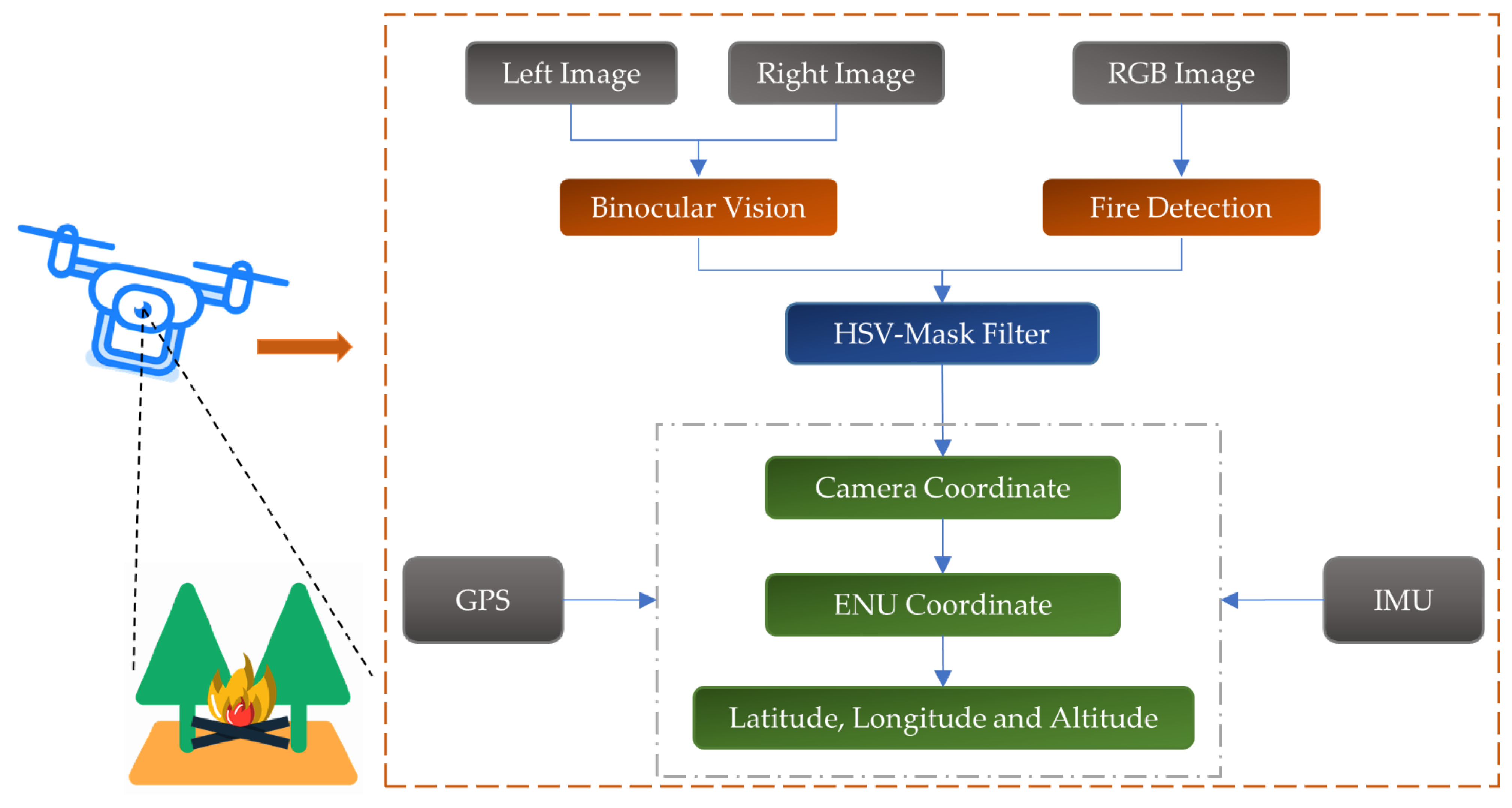
In this paper, we proposed a fire detection and spatial localization scheme for forest fire patrol. The sketch map is shown in Figure 4. The key components of the scheme are threefold. The first is forest fire detection. It is the core of this system and affects the overall performance. Here, we apply a lightweight deep learning object detection model NanoDet for forest fire monitoring to indicate where the fire is in the image. Compared with traditional image processing methods, the deep learning-based approach is more flexible and powerful in feature extraction and can adapt to complex forest scenes. Second, a depth map via binocular stereo vision is obtained and, based on this, the relative location of the fire can be measured. Then, an HSV-Mask filter algorithm is proposed to estimate the location of the fire, based on the fire detection information. Finally, the attitude data transforms the fire location from the original camera frame to the earth-north-up (ENU) frame. Then, the forest fire coordinates in the ENU frame are converted to longitude, latitude, and altitude via conversion equations to accurately acquire fire location.
3.1. Forest Fire Detection
3.1.1. NanoDet
NanoDet is an anchor-free object detection neural network, which makes a lightweight improvement based on FCOS [21]. Compared with the anchor-based detectors, such as YOLOv3 [22], YOLOv4 [23], and SSD [24], the anchor-free detectors can reduce the complexity of detection heads, as well as the number of predictions for each image [25].
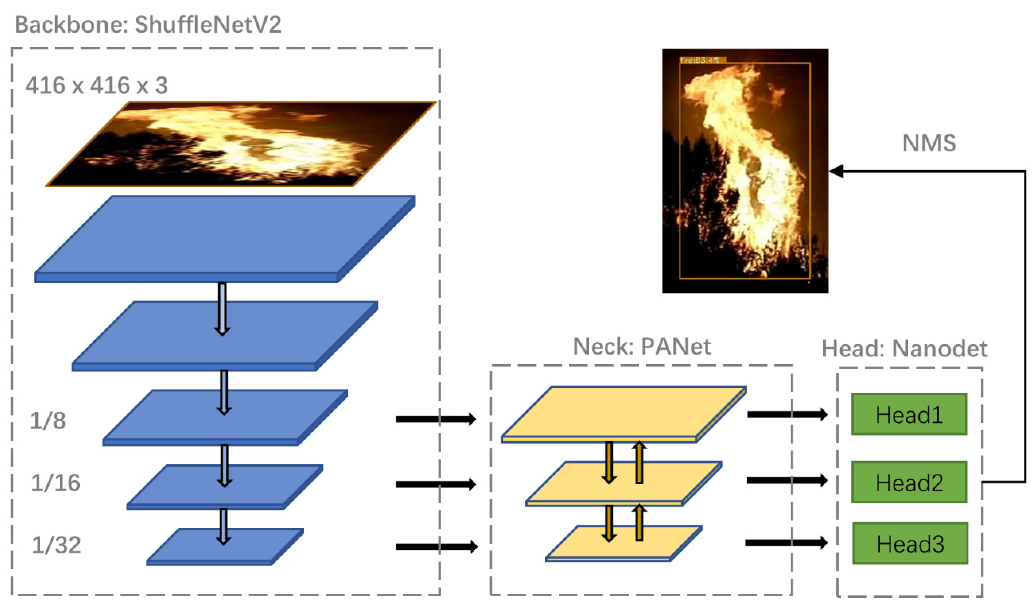
The network architecture of NanoDet is shown in Figure 5. To get a better trade-off between inference latency and accuracy, the input frame size is set to 416 × 416 pixels, and ShuffleNet-V2 [26] is employed as its backbone to extract features of forest fires. The ShuffleNet-V2 block comprises pointwise convolution, depthwise convolution, and channel shuffle operation. With the advantage of computation reduction, it ensures the model extracts the same features by stacking blocks as well. After that, the feature maps 8×, 16×, and 32× down-sampling rates connected to a path aggregation network (PANet) [27] for feature fusion. Compared with the top-down fusion in the feature pyramid network (FPN) [28], PANet adds a bottom-up path, which can better integrate high-level semantic features and low-level spatial features so that targets of different scales have good recognition effects. Then, the fusion features of different scales are fed into the lightweight detection head, each of which generates a classification branch and a regression branch. The classification branch integrates the classification score and the IoU score. Label softening is carried out to change the discrete category labels into continuous labels (0~1). In this way, the classification score and the intersection over union (IoU) score can be combined for joint representation, and prediction accuracy can be improved. The regression branch introduces the idea of probability distribution to predict the distance from the center point to four sides of a bounding box (left, right, top, and bottom), and each side predicts N values (N is set as a hyperparameter). Therefore, a total of 4 × N values are predicted to represent the distribution of the regression bounding box, and each distribution determines each distance. Finally, we use non-maximum suppression (NMS) algorithm to filter redundant bounding boxes to obtain the final detection results.
3.1.2. Loss Function
NanoDet uses the idea of generalized focal loss (GFL) [29] for loss function, which is divided into three parts:
The first part is the quality focal loss (QFL), which is used to adjust classification quality. As the classification branch introduces the joint representation of classification score and IoU score, its supervised labels become continuous values. For this reason, QFL extends the classical Focal Loss [30] in the continuous domain, and its expression is shown in Equation (1).
where represents the label from 0 to 1, represents the predicted value, and is a modulating factor.
The second part is the distribution focal loss (DFL), which is used to adjust the distribution of bounding boxes. To quickly focus on increasing the probabilities of values in the vicinity of the target, DFL is introduced to guide bounding box regression, and its expression is shown in Equation (2).
where and represent the left and right positions of label , respectively, and represent the probabilities of and , respectively, and their values are obtained by the Softmax function.
The last part is the intersection over union loss (GIoU) [31]. Compared with the traditional IoU algorithm, the GIoU can optimize the non-overlap area better and improve the overall performance. The GIoU and GIoU loss are shown in Equations (3) and (4), respectively.
where represents the intersection area of the bounding box and ground truth, represents the union area of the bounding box and ground truth, and represents the minimum enclosing area of the bounding box and ground truth.
The final loss function is a weighted sum of the three parts. The expression is shown in Equation (5). The weight coefficients can be adjusted during training to make the final model have a certain emphasis. Due to the high accuracy requirement of forest fire detection in our system, false detection and missed detection will greatly impact practical application. Therefore, the proportion of QFL should be appropriately increased. In our system, the parameters (, , and ) are set to 2.0, 0.25, and 1.5, respectively, which perform better through experiments.
3.2. Binocular Stereo Vision
3.2.1. Geometric Model
A binocular camera is generally composed of a left camera and a right camera. The principle of binocular stereo vision to obtain depth information calculates the disparity between the left and right images of a point in space. The geometric model of binocular stereo vision is shown in Figure 6. The points ( and ) are the center of the left and right camera’s aperture. If there is a point in space, then its image in the left and right camera are and respectively. We can calculate the depth of the target point by similar triangles, and the expression can be written as:
After simplifying, we can write as:
where is the parallax, representing the disparity in direction caused by observing the same object from two points at a certain distance.
Obviously, in Equation (7), the distance is inversely proportional to the disparity . Since the disparity is at least one pixel, the depth of binocular stereo vision has a theoretical upper bound, which is determined by the focal length and the baseline distance .
In order to get the three-dimensional coordinates of the point (, , ), we also need to calculate the -axis and -axis values. Assume that the image plane coordinates of point are and , and the pixel coordinates are and . The camera coordinates to the image plane coordinate can be converted by similar triangles in the imaging model, as shown in Equation (8).
Similarly, converting from image plane coordinates to pixel coordinates requires scaling and translating, and the expression can be written as:
where and are the scaling factor and the translating factor, respectively, and they have different values on each axis.
Combining the Equations (8) and (9), we can get the camera coordinates of the point in Equation (10).
where and , and they are in pixels. Generally, we call , , and as the camera intrinsic.
3.2.2. Stereo Matching
Stereo matching is the core of the binocular stereo vision system, which matches corresponding pixels in two or more viewpoints and obtains a disparity image. Semi-Global Block Matching (SGBM) [32,33,34] is more efficient in stereo matching than a local matching algorithm. It is widely used, but much more complicated. The flow of the SGBM algorithm is shown in Figure 7. For input images, the Birchfield and Tomasi matching cost (BT cost) [35] will be aggregated in two paths. The first path uses the Sobel operator for horizontal gradient filtering and then calculates the BT cost. The second path calculates the BT cost directly. The BT cost processed by the Sobel-X operator retains more edge features. In contrast, the untreated BT cost retains the features of the original image, which improves the accuracy of the cost by combing the two paths. After aggregating the costs, we need to calculate the cost block, which is to substitute the value of each pixel with the sum of the surrounding values, improving the robustness of matching. Then, the SGM [32] algorithm is used to constrain the current pixel by multiple paths in the surrounding direction to realize multipath aggregation. Finally, the post-processing part includes confidence detection, sub-pixel interpolation, and left-right consistency check, and their primary function is to smooth disparity and eliminate the disparity error problems.
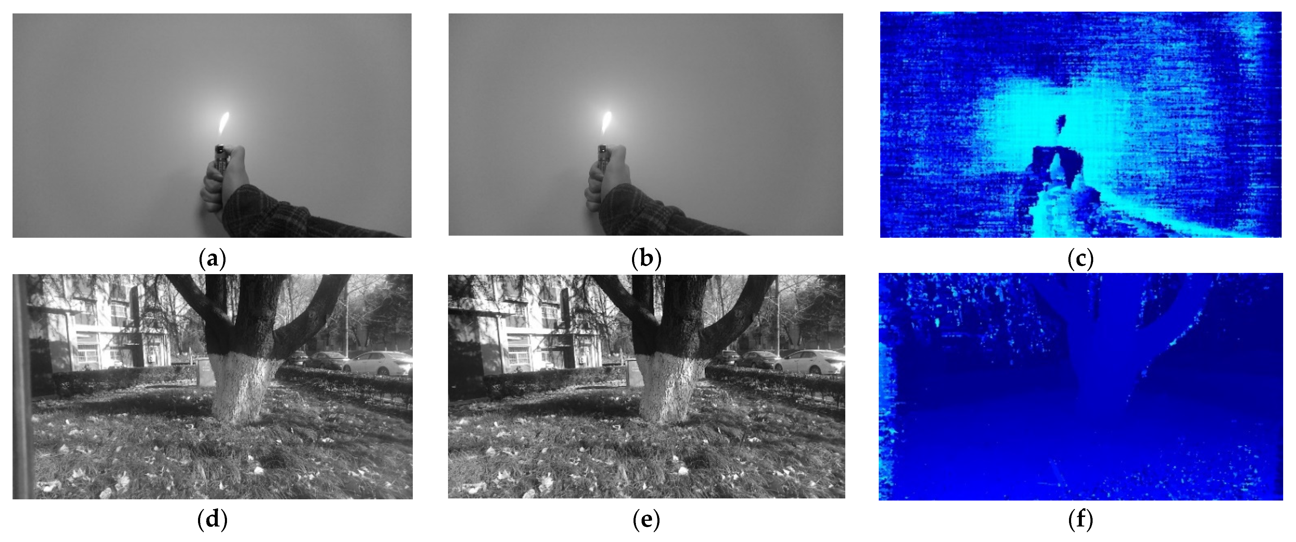
According to the SGBM algorithm above, we can obtain the depth information and get 3D coordinates through the binocular camera, as shown in Figure 8. The images in the first and second columns were token from OAK-D’s left and right cameras, respectively, which have a resolution of 1280 × 720. The third column shows the disparity maps calculated by the above algorithm. It can be seen that depth information is well recovered. And its theoretical measuring range of 0.3 to 28 m is sufficient for our forest fire inspection tasks.
3.3. Forest Fire Localization
3.3.1. HSV-Mask Filter
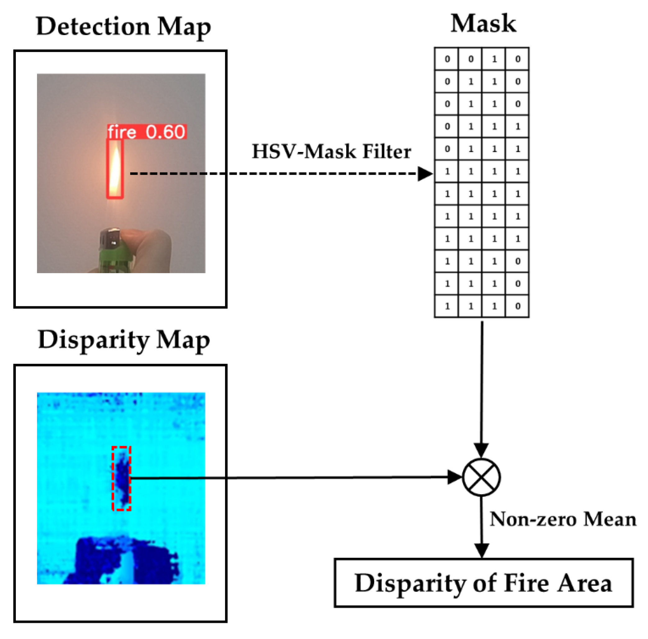
In our forest fire detection model, the rectangle box information () of the fire position can be recognized in a two-dimensional RGB image. However, the objects in the rectangle box are not only flame targets, but also redundant background information, which will interfere with the accuracy of depth calculation by binocular vision. Therefore, we proposed the HSV-Mask filter method for optimization, as shown in Figure 9. HSV color conversion is performed on the area of rectangle boxes, which are detected in the RGB image. The HSV mask is made according to the thresholds of flame color, as shown in Equation (11). Note that the thresholds are derived from experiments with our forest fire dataset.
where the maximum and minimum values of , and are 1 and 0.
After obtaining the mask matrix , multiply the mask by the corresponding points in the disparity map represented as the matrix . Finally, the mean of the non-zero pixels’ values is calculated as the z-axis value of the fire area, and the transformed center point coordinates of the rectangle box calculated by Equation (10) are taken as the x-axis and y-axis values of the fire area. The equation of calculating the disparity of the fire area is shown in Equation (12).
where and represent the height and width of the rectangle box.
3.3.2. Coordinate Transformation
To obtain the longitude, latitude, and altitude of the fire area, the location of the fire in the camera frame needs to be converted to the LLA frame. It is divided into three conversions, which need to combine the attitude and location information of the UAV.
The first conversion is from the camera frame to the ENU frame. The pitch angle, roll angle, and yaw angle of the UAV can be obtained from the IMU module. The inclination angle of the camera relative to the UAV is fixed at 30° in our system. According to the formulas in [36], the camera frame coordinates are first converted to the UAV’s body frame coordinates , and then to the ENU coordinates .
The second conversion is from the ENU frame to the earth-centered-earth-fixed (ECEF) frame. In order to get the ECEF coordinates of the fire area, we should know the body coordinates of the UAV in the ECEF frame first. From the GPS module, we can obtain the LLA coordinates of the UAV, which can be represented as . According to the elliptic geometric model and formulas in [37], the body coordinates of the UAV in ECEF frame can be calculated.
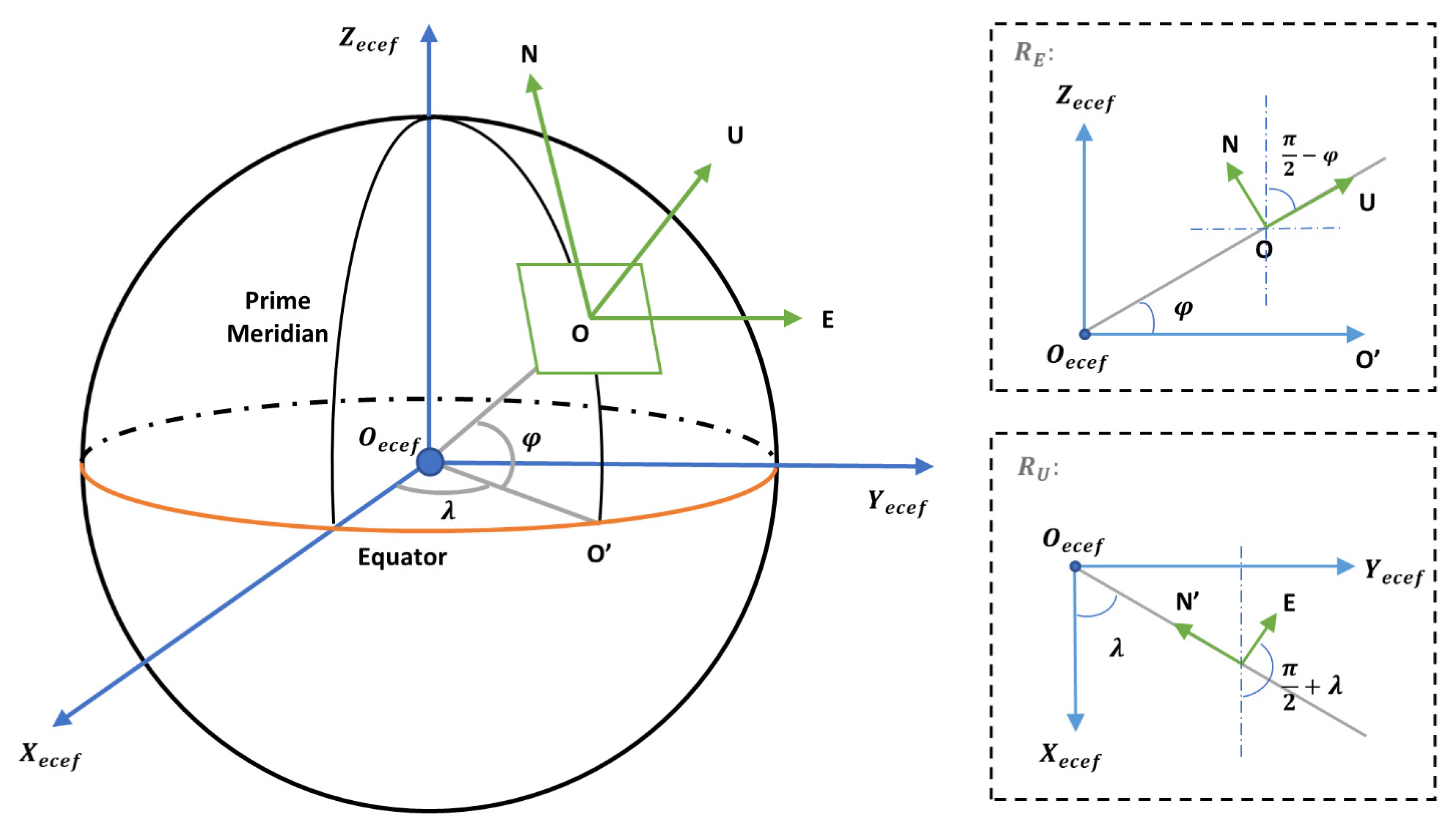
The conversion between the ENU frame and the ECEF frame needs two rotations. As shown in the right of Figure 10, the first rotation is to rotate the ENU frame around E-axis by so that the -axis is parallel to -axis. The second rotation is to rotate around U-axis by , which makes -axis and -axis parallel. The rotation matrix of this process can be expressed in Equation (13).
where and represent the longitude and latitude of the UAV’s body frame, respectively.
Assume that the coordinate of the detected fire area in the ECEF frame is , which can be calculated by Equation (14):
The final conversion is from the ECEF frame to the LLA frame. the LLA coordinates of the fire area , can be obtained iteratively [38] by Equation (15):
where and are the eccentricity of the ellipsoid the radius of curvature of the reference ellipsoid, respectively.
4. Results
4.1. Detector Training
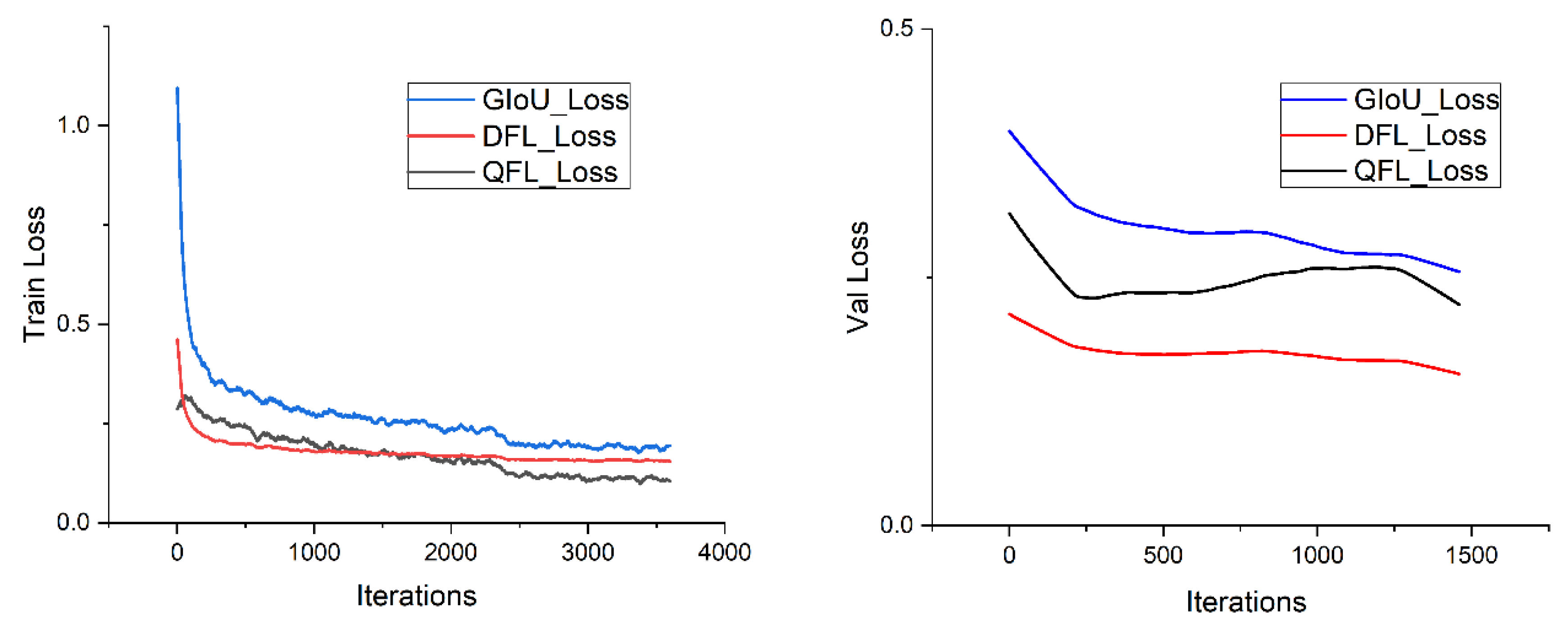
The forest fire detection model NanoDet is built by PyTorch framework and trained on a server with an Intel Xeon processor and one NVIDIA 2080 ti GPU. We use the stochastic gradient method (SGD) as the optimizer to update parameters. The initial learning rate, batch size, and epoch are set to 0.003, 16, and 200, respectively. In addition, we employ some training tricks to speed up the convergence and increase the accuracy of the model, which will be proved to be effective with experimental data in Section 4.2. After tens of thousands of iterations, the model tends to converge and be stable. Figure 11 shows the loss curve, with a training loss recorded every 20 steps and a validation loss recorded every 50 steps.
4.2. Recognition Performance and Accuracy
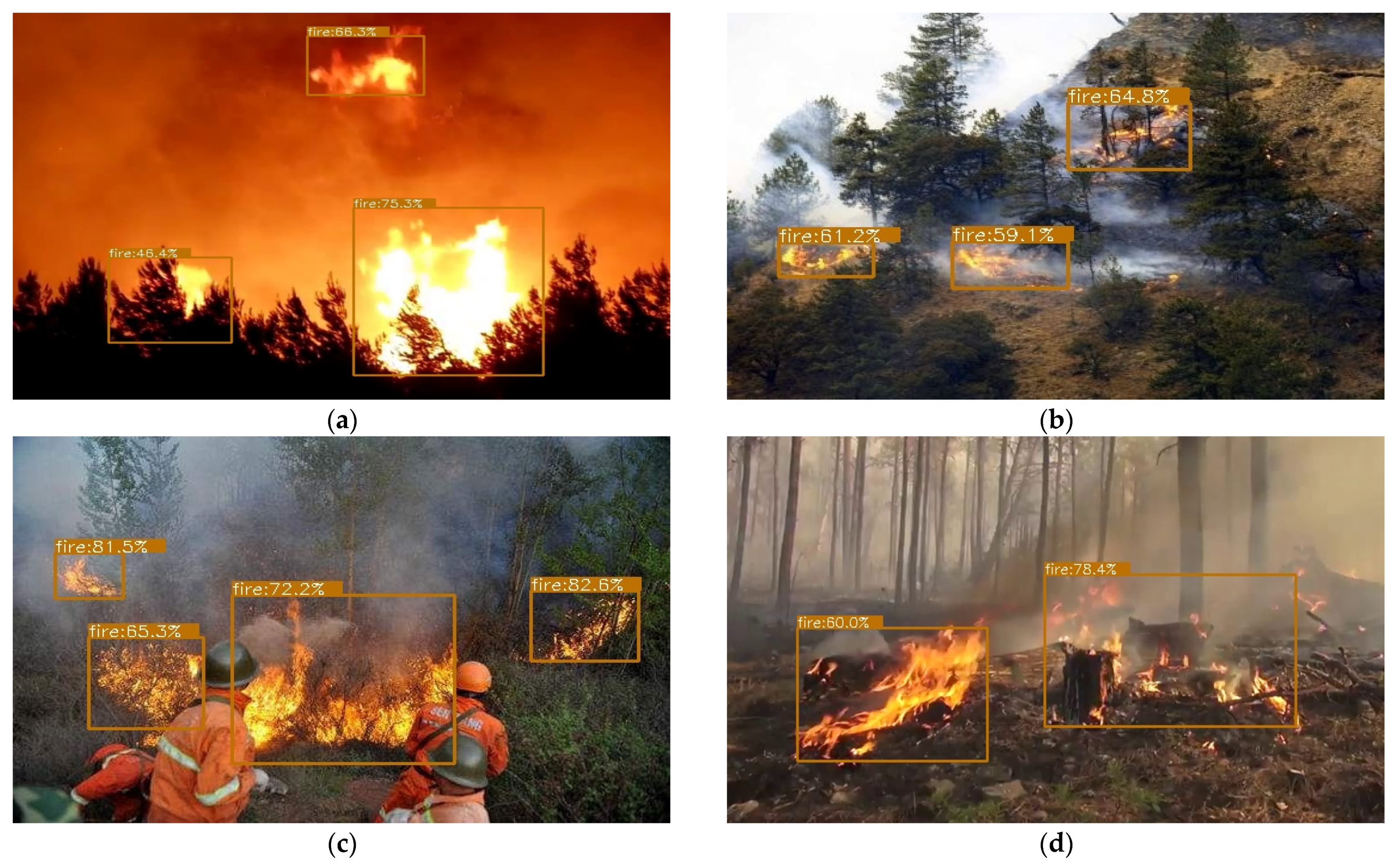
In this section, we adopt Microsoft COCO criteria [39] for model evaluation and compare our model with typical lightweight detectors. In addition, we also compare the precision under changed training strategies in the forest fire detector, such as replacing the MultiStep learning rate strategy with cosine decay [40,41], using the random horizontal flip and random color jittering for data augmentation [41]. As is shown in Table 2, Yolov5-s performs better than other detectors in terms of mAP due to its large resolution and stronger network structure, which can reserve more details and extract more features. However, compared with the NanoDet used in this paper, especially with the training strategy changed, it is weaker in terms of parameter number and inference speed. After using data augmentation and the learning rate adjustment strategy, the NanoDet fire detector is improved by 1.6% in mAP, 1.4% in , and 0.4% in , and has the highest FPS. Therefore, NanoDet achieves a better trade-off between model size and accuracy, and a more comprehensive performance in practical applications. The detection results of different scenes on the test dataset are shown in Figure 12. Most of the fire areas can be well recognized and have high confidence, while the microscopic fire objects cannot be detected due to the distance and the image resolution.
4.3. Experiment
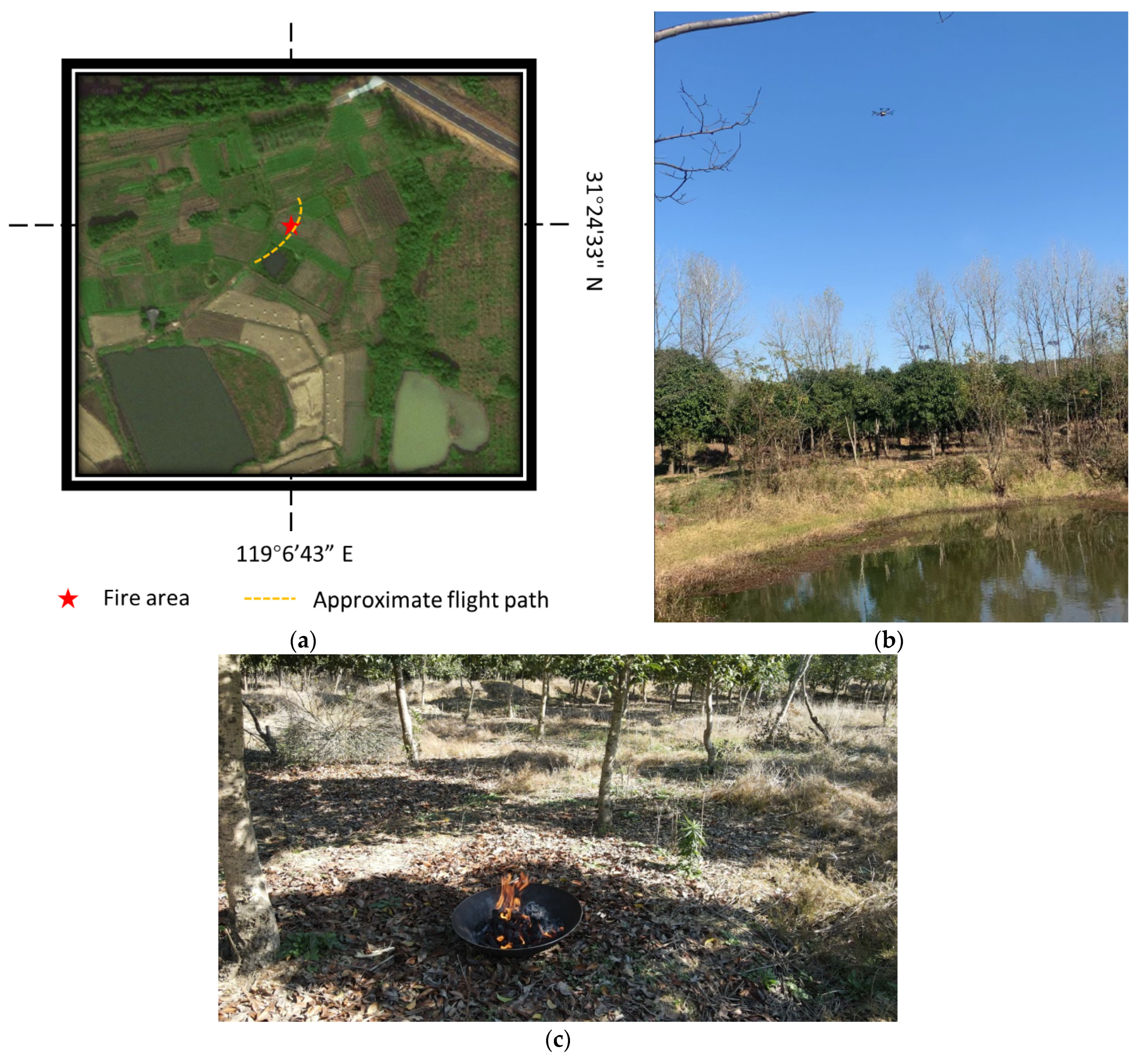
In order to verify the performance of our system in real-world tasks, we chose a forest area in Gaochun, Nanjing, China, for fire simulation. The exact longitude and latitude of simulated fire were at (119°6′43.26″ E, 31°24′33.92″ N), and the measured altitude was 8.7067 m. The UAV was going to fly over this area, as shown in Figure 13a, and would raise an alarm and send the location of the fire area to the ground when the fire was detected. As shown in Figure 13b, the height of trees in this area was less than 8 m, so the flight altitude in this experiment was about 8 m to 15 m. The fire simulator used an iron pot as a container in case the fire was out of control. Combustibles, such as wood, kerosene, and straw, were selected to ensure long-term combustion.
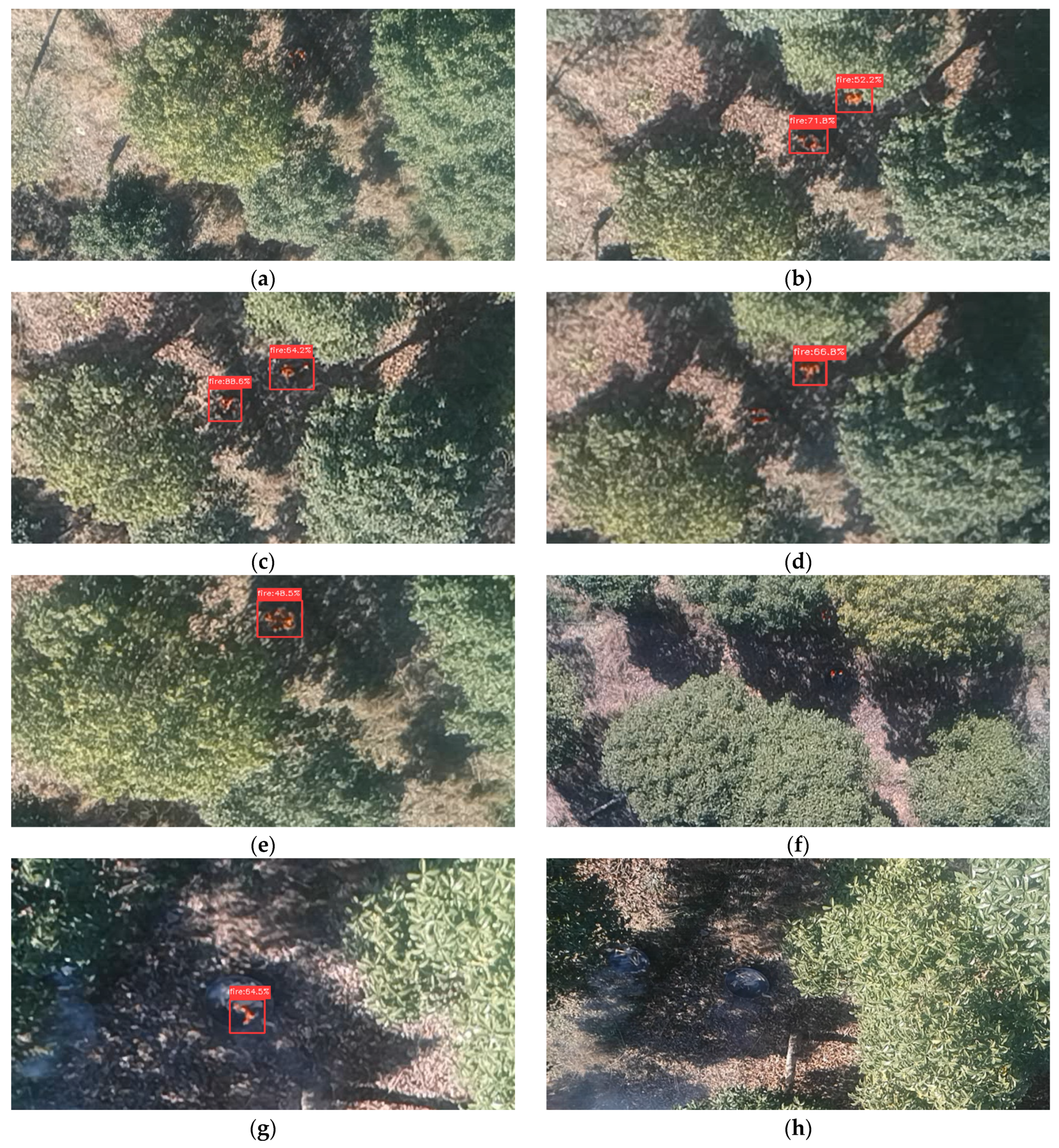
Before the flight, the equipment is adjusted to ensure that each module can work properly. During the inspection process, the forest fire detector and binocular stereo vision work in real-time and save the video stream. When a fire is detected, the alarm and the longitude and latitude information will be sent to the ground center. Meanwhile, this information will also be saved as log files in the memory card, including frame number, the bounding boxes, the GPS information, and the estimated longitude and latitude values of the fire area. In our experiment, a video of 1 min and 33 s is collected, with 1356 frames in total. A partial frame fragment selected from the video stream is shown in Figure 14. In this video, there are 197 frames with flame objects, and 176 of them are detected with an accuracy of 89.34%. Some flames are too small to be detected (such as Figure 14a,d,f), and others are successfully detected. The flame targets in the images where no flame is detected are scattered and small, resulting in missing details at pixel level. Without enough characteristic information to characterize the flame, the performance of the detector will deteriorate, and missing detections will occur.
In addition, we use the log data corresponding to the above frames to evaluate the localization performance of the fire area. The coordinates of the detected fire areas are listed in Table 3. The mean absolute errors of the estimated longitude, latitude, and altitude are , , and 0.1228, respectively, which meets our precision requirements and is sufficient for the forest fire inspection.
5. Conclusions and Discussion
In this paper, we propose a forest fire detection and spatial localization scheme and develop a system carried on the UAV for real-time inspection. The system is equipped an OAK-D camera as the main processing unit, which integrates binocular cameras and an RGB camera, and a Raspberry PI. They have the advantage of strong computing power, but with low-power consumption. We selected NanoDet as the detector in forest fire detection, which has a lightweight structure and high accuracy. Both the sufficient dataset and advanced training tricks we adopted contributes to the performance enhancement. However, the forest fire detector can only get the location in images. If the 3D location information can be obtained, it would greatly help the firefighting works in the forest. In the spatial localization scheme of the fire area, we first used an HSV-Mask filter on the fire area detected by the detector. Then, we combined it with the depth map calculated by the binocular stereo vision to obtain the depth value of the area. The data from GPS and IMU were fused to transform the frame into the LLA frame to get the latitude and longitude coordinates of the target fire. Finally, to study the specific results of this scheme, we carried out a forest fire simulation experiment. In the real-world detection, 89.34% of the frames with flame were successfully detected. Meanwhile, the error of latitude and longitude is in the order of degrees. The experimental results showed that the performance of detection and localization meets our needs and can be applied to the real-world forest fire inspection.
Nevertheless, as the core of our scheme, the detector is weak in detecting small targets (Figure 14 and Table 2). Due to lower resolution, fewer features, and more noise, small object detection is one of the challenging problems in object detection [42]. For further research, we will focus on two aspects. On one hand, we will optimize the recognition of small flames on the forest fire detection algorithm, which will help both the inspection of the UAV and the detection of early fire. On the other hand, we will seek other sensing cameras and fuse them for further analysis, such as infrared cameras, hyperspectral cameras, polarizing cameras, etc.
Author Contributions
Conceptualization, K.L. and Y.L. (Yunfei Liu); Data curation, J.L., Y.L. (Yuhao Lv) and H.L.; Funding acquisition, Y.L. (Yunfei Liu); Methodology, K.L.; Resources, J.L.; Software, K.L. and R.X.; Validation, H.L.; Visualization, J.L. and Y.L. (Yuhao Lv); Writing—original draft, K.L.; Writing—review & editing, R.X. and Y.L. (Yunfei Liu). All authors have read and agreed to the published version of the manuscript.
Funding
This research was funded by the Postgraduate Research &Practice Innovation Program of Jiangsu Province (grant number KYCX21_0876) and the National Key R&D Program of China (grant number 2017YFD0600904).
Data Availability Statement
Conflicts of Interest
The authors declare no conflict of interest.
References
- Yuan, C.; Zhang, Y.; Liu, Z. A survey on technologies for automatic forest fire monitoring, detection, and fighting using unmanned aerial vehicles and remote sensing techniques. Can. J. For. Res. 2015, 45, 783–792. [Google Scholar] [CrossRef]
- Dios, J.M.-D.; Arrue, B.; Ollero, A.; Merino, L.; Gómez-Rodríguez, F. Computer vision techniques for forest fire perception. Image Vis. Comput. 2008, 26, 550–562. [Google Scholar] [CrossRef]
- Lee, W.; Kim, S.; Lee, Y.-T.; Lee, H.-W.; Choi, M. Deep neural networks for wild fire detection with unmanned aerial vehicle. In Proceedings of the 2017 IEEE International Conference on Consumer Electronics (ICCE), Taipei, Taiwan, 12–14 June 2017; pp. 252–253. [Google Scholar]
- Wang, Z.; Zhang, H.; Hou, M.; Shu, X.; Wu, J.; Zhang, X. A Study on Forest Flame Recognition of UAV Based on YOLO-V3 Improved Algorithm. In Recent Advances in Sustainable Energy and Intelligent Systems; Springer: Singapore, 2021; pp. 497–503. [Google Scholar]
- Hossain, F.A.; Zhang, Y.M.; Tonima, M.A. Forest fire flame and smoke detection from UAV-captured images using fire-specific color features and multi-color space local binary pattern. J. Unmanned Veh. Syst. 2020, 8, 285–309. [Google Scholar] [CrossRef]
- Zhang, J.; Li, W.; Yin, Z.; Liu, S.; Guo, X. Forest fire detection system based on wireless sensor network. In Proceedings of the 2009 4th IEEE Conference on Industrial Electronics and Applications, Xi’an, China, 25–27 May 2009; pp. 520–523. [Google Scholar]
- Chen, Y.; Zhang, Y.; Xin, J.; Wang, G.; Mu, L.; Yi, Y.; Liu, H.; Liu, D. UAV image-based forest fire detection approach using convolutional neural network. In Proceedings of the 2019 14th IEEE Conference on Industrial Electronics and Applications (ICIEA), Xi’an, China, 19–21 June 2019; pp. 2118–2123. [Google Scholar]
- Ryu, J.; Kwak, D. Flame Detection Using Appearance-Based Pre-Processing and Convolutional Neural Network. Appl. Sci. 2021, 11, 5138. [Google Scholar] [CrossRef]
- Borges, P.; Izquierdo, E. A Probabilistic Approach for Vision-Based Fire Detection in Videos. IEEE Trans. Circuits Syst. Video Technol. 2010, 20, 721–731. [Google Scholar] [CrossRef]
- Yuan, C.; Ghamry, K.A.; Liu, Z.; Zhang, Y. Unmanned aerial vehicle based forest fire monitoring and detection using image processing technique. In Proceedings of the 2016 IEEE Chinese Guidance, Navigation and Control Conference (CGNCC), Nanjing, China, 12–14 August 2016; pp. 1870–1875. [Google Scholar]
- Jindal, P.; Gupta, H.; Pachauri, N.; Sharma, V.; Verma, O.P. Real-Time Wildfire Detection via Image-Based Deep Learning Algorithm. In Soft Computing: Theories and Applications; Springer: Singapore, 2021; pp. 539–550. [Google Scholar]
- Barmpoutis, P.; Dimitropoulos, K.; Kaza, K.; Grammalidis, N. Fire Detection from Images Using Faster R-CNN and Multidimensional Texture Analysis. In Proceedings of the ICASSP 2019–2019 IEEE International Conference on Acoustics, Speech and Signal Processing (ICASSP), Brighton, UK, 12–17 May 2019; pp. 8301–8305. [Google Scholar]
- Lu, P.; Zhao, Y.; Xu, Y. A Two-Stream CNN Model with Adaptive Adjustment of Receptive Field Dedicated to Flame Region Detection. Symmetry 2021, 13, 397. [Google Scholar] [CrossRef]
- Xu, R.; Lin, H.; Lu, K.; Cao, L.; Liu, Y. A Forest Fire Detection System Based on Ensemble Learning. Forests 2021, 12, 217. [Google Scholar] [CrossRef]
- Li, P.; Zhao, W. Image fire detection algorithms based on convolutional neural networks. Case Stud. Therm. Eng. 2020, 19, 100625. [Google Scholar] [CrossRef]
- Chino, D.Y.T.; Avalhais, L.P.S.; Rodrigues, J.F.; Traina, A.J.M. BoWFire: Detection of Fire in Still Images by Integrating Pixel Color and Texture Analysis. In Proceedings of the 2015 28th SIBGRAPI Conference on Graphics, Patterns and Images, Salvador, Brazil, 26–29 August 2015; pp. 95–102. [Google Scholar]
- Cazzolato, M.T.; Avalhais, L.; Chino, D.; Ramos, J.S.; de Souza, J.A.; Rodrigues-Jr, J.F.; Traina, A. Fismo: A compilation of datasets from emergency situations for fire and smoke analysis. In Proceedings of the Brazilian Symposium on Databases-SBBD, Uberlândia, Brazil, 2–5 October 2017; pp. 213–223. [Google Scholar]
- Kucuk, G.; Kosucu, B.; Yavas, A.; Baydere, S. FireSense: Forest Fire Prediction and Detection System using Wireless Sensor Networks. In Proceedings of the 4th IEEE/ACM International Conference on Distributed Computing in Sensor Systems (DCOSS’08), Santorini, Greece, 11–14 June 2008. [Google Scholar]
- Kong, S.G.; Jin, D.; Li, S.; Kim, H. Fast fire flame detection in surveillance video using logistic regression and temporal smoothing. Fire Saf. J. 2016, 79, 37–43. [Google Scholar] [CrossRef]
- Douce, G.K.; Moorhead, D.J.; Bargeron, C.T., IV. Forestry Images. org: High resolution image archive and web-available image system. J. For. Sci. 2001, 47, 77–79. [Google Scholar]
- Tian, Z.; Shen, C.; Chen, H.; He, T. FCOS: Fully convolutional one-stage object detection. In Proceedings of the IEEE/CVF International Conference on Computer Vision, Seoul, Korea, 27–28 October 2019; pp. 9627–9636. [Google Scholar] [CrossRef] [Green Version]
- Redmon, J.; Farhadi, A. Yolov3: An incremental improvement. arXiv 2018, arXiv:1804.02767. [Google Scholar]
- Bochkovskiy, A.; Wang, C.-Y.; Liao, H.-Y.M. YOLOv4: Optimal Speed and Accuracy of Object Detection. arXiv 2020, arXiv:2004.10934. [Google Scholar]
- Liu, W.; Anguelov, D.; Erhan, D.; Szegedy, C.; Reed, S.; Fu, C.-Y.; Berg, A.C. Ssd: Single shot multibox detector. In Proceedings of the 14th European Conference on Computer Vision, Amsterdam, The Netherlands, 8–16 October 2016; pp. 21–37. [Google Scholar]
- Ge, Z.; Liu, S.; Wang, F.; Li, Z.; Sun, J. Yolox: Exceeding yolo series in 2021. arXiv 2021, arXiv:2107.08430. [Google Scholar]
- Ma, N.; Zhang, X.; Zheng, H.-T.; Sun, J. Shufflenet v2: Practical guidelines for efficient cnn architecture design. In Proceedings of the European Conference on Computer Vision (ECCV), Munich, Germany, 8–14 September 2018; pp. 116–131. [Google Scholar]
- Wang, K.; Liew, J.H.; Zou, Y.; Zhou, D.; Feng, J. PANet: Few-Shot Image Semantic Segmentation With Prototype Alignment. In Proceedings of the 2019 IEEE/CVF International Conference on Computer Vision (ICCV), Seoul, Korea, 27 October–2 November 2019; pp. 9197–9206. [Google Scholar]
- Lin, T.-Y.; Dollar, P.; Girshick, R.; He, K.; Hariharan, B.; Belongie, S. Feature pyramid networks for object detection. In Proceedings of the IEEE Conference on Computer Vision and Pattern Recognition, Honolulu, HI, USA, 21–26 July 2017; pp. 2117–2125. [Google Scholar] [CrossRef] [Green Version]
- Li, X.; Wang, W.; Wu, L.; Chen, S.; Hu, X.; Li, J.; Tang, J.; Yang, J. Generalized focal loss: Learning qualified and distributed bounding boxes for dense object detection. arXiv 2020, arXiv:2006.04388. [Google Scholar]
- Lin, T.-Y.; Goyal, P.; Girshick, R.; He, K.; Dollár, P. Focal loss for dense object detection. In Proceedings of the 2017 IEEE International Conference on Computer Vision, Venice, Italy, 22–29 October 2017; pp. 2980–2988. [Google Scholar]
- Rezatofighi, H.; Tsoi, N.; Gwak, J.; Sadeghian, A.; Reid, I.; Savarese, S. Generalized Intersection Over union: A metric and a Loss for Bounding Box Regression. In Proceedings of the IEEE Conference on Computer Vision and Pattern Recognition 2019, Long Beach, CA, USA, 15–20 June 2019; pp. 658–666. [Google Scholar] [CrossRef] [Green Version]
- Hirschmuller, H. Accurate and Efficient Stereo Processing by Semi-Global Matching and Mutual Information. In Proceedings of the 2005 IEEE Computer Society Conference on Computer Vision and Pattern Recognition (CVPR’05), San Diego, CA, USA, 20–25 June 2005; pp. 807–814. [Google Scholar]
- Tatar, N.; Saadatseresht, M.; Arefi, H. The Effect of Shadow Area on Sgm Algorithm and Disparity Map Refinement from High Resolution Satellite Stereo Images. Int. Arch. Photogramm. Remote Sens. Spat. Inf. Sci. 2017, 42, 281–286. [Google Scholar] [CrossRef] [Green Version]
- Mei, X.; Sun, X.; Zhou, M.; Jiao, S.; Wang, H.; Zhang, X. On building an accurate stereo matching system on graphics hardware. In Proceedings of the IEEE International Conference on Computer Vision Workshops (ICCV), Barcelona, Spain, 6–13 November 2011; pp. 467–474. [Google Scholar] [CrossRef]
- Birchfield, S.; Tomasi, C. Depth Discontinuities by Pixel-to-Pixel Stereo. Int. J. Comput. Vis. 1999, 35, 269–293. [Google Scholar] [CrossRef]
- Sanyal, S.; Bhushan, S.; Yazi, S. Detection and Location Estimation of Object in Unmanned Aerial Vehicle using Single Camera and GPS. In Proceedings of the 2020 First International Conference on Power, Control and Computing Technologies (ICPC2T), Raipur, India, 3–5 January 2020; pp. 73–78. [Google Scholar]
- Zheng, L.; Zhu, Y.; Xue, B.; Liu, M.; Fan, R. Low-Cost GPS-Aided LiDAR State Estimation and Map Building. In Proceedings of the 2019 IEEE International Conference on Imaging Systems and Techniques (IST), Abu Dhabi, United Arab Emirates, 9–10 December 2019; pp. 1–6. [Google Scholar]
- Sankowski, M. Target course estimation in tracking filters using local Cartesian coordinates. In Proceedings of the 2012 13th International Radar Symposium, Warsaw, Poland, 23–25 May 2012; pp. 515–520. [Google Scholar]
- Lin, T.Y.; Maire, M.; Belongie, S.; Hays, J.; Perona, P.; Ramanan, D.; Dollár, P.; Zitnick, C.L. Microsoft coco: Common objects in context. In Proceedings of the 13th European Conference on Computer Vision, Zurich, Switzerland, 6–12 September 2014; pp. 740–755. [Google Scholar]
- Loshchilov, I.; Hutter, F. Sgdr: Stochastic gradient descent with warm restarts. arXiv 2016, arXiv:1608.03983. [Google Scholar]
- He, T.; Zhang, Z.; Zhang, H.; Zhang, Z.; Xie, J.; Li, M. Bag of Tricks for Image Classification with Convolutional Neural Networks. In Proceedings of the 2019 IEEE/CVF Conference on Computer Vision and Pattern Recognition (CVPR), Long Beach, CA, USA, 15–20 June 2019; pp. 558–567. [Google Scholar]
- Kim, M.; Jeong, J.; Kim, S. ECAP-YOLO: Efficient Channel Attention Pyramid YOLO for Small Object Detection in Aerial Image. Remote Sens. 2021, 13, 4851. [Google Scholar] [CrossRef]
Figure 1.
The samples of the dataset. (a) Forest fire images containing ground fires, trunk fires, canopy fires, etc.; and (b) non-fire images containing sunset, red leaves, red lantern, etc.
Figure 1.
The samples of the dataset. (a) Forest fire images containing ground fires, trunk fires, canopy fires, etc.; and (b) non-fire images containing sunset, red leaves, red lantern, etc.

Figure 2.
Annotation examples. (a) The large area labeling method. The flames are large area and continuous. (b) The small area labeling method. The flames are scattered and separated by the firefighter and trees.
Figure 2.
Annotation examples. (a) The large area labeling method. The flames are large area and continuous. (b) The small area labeling method. The flames are scattered and separated by the firefighter and trees.

Figure 3.
The composition of the hardware system, containing the UAV, the ground controller, the OAK-D camera, the Raspberry Pi controller, and the GPS module.
Figure 3.
The composition of the hardware system, containing the UAV, the ground controller, the OAK-D camera, the Raspberry Pi controller, and the GPS module.

Figure 4.
The sketch map of our scheme, containing binocular vision, fire detection, and location.

Figure 5.
Overview of the network architecture. It consists of three main parts: (1) Backbone: ShuffleNetV2, (2) Neck: PANet, and (3) Head: NanoDet head. The backbone, neck, and head are for feature extraction, feature fusion, and classification and regression, respectively.
Figure 5.
Overview of the network architecture. It consists of three main parts: (1) Backbone: ShuffleNetV2, (2) Neck: PANet, and (3) Head: NanoDet head. The backbone, neck, and head are for feature extraction, feature fusion, and classification and regression, respectively.

Figure 6.
The geometric model of the binocular system. is the focal length, is the baseline distance of the binocular stereo vision system, and is the distance from the point to the camera.
Figure 6.
The geometric model of the binocular system. is the focal length, is the baseline distance of the binocular stereo vision system, and is the distance from the point to the camera.

Figure 7.
The flow of the SGBM algorithm.

Figure 8.
Display of disparity calculation results. (a) The left image of the flame. (b) The right image of the flame. (c) The disparity map of the flame. (d) The left image of the tree. (e) The right image of the tree. (f) The disparity map of the tree.
Figure 8.
Display of disparity calculation results. (a) The left image of the flame. (b) The right image of the flame. (c) The disparity map of the flame. (d) The left image of the tree. (e) The right image of the tree. (f) The disparity map of the tree.

Figure 9.
The flow chart of HSV-Mask Filter. The detected bounding box is transformed into a mask matrix by HSV-Mask filter, and then multiplied by the corresponding disparity matrix. Finally, the non-zero mean is calculated to get the disparity value of the fire area.
Figure 9.
The flow chart of HSV-Mask Filter. The detected bounding box is transformed into a mask matrix by HSV-Mask filter, and then multiplied by the corresponding disparity matrix. Finally, the non-zero mean is calculated to get the disparity value of the fire area.

Figure 10.
The relationship between the ENU frame and the ECEF frame, and the schematic diagram of the rotation is on the right of the figure.
Figure 10.
The relationship between the ENU frame and the ECEF frame, and the schematic diagram of the rotation is on the right of the figure.

Figure 11.
The loss curve of training and validation. As training loss stabilize, so does the validation loss.
Figure 11.
The loss curve of training and validation. As training loss stabilize, so does the validation loss.

Figure 12.
The detection results on our test dataset. (a) The dark night scene; (b) the mountainside scene; (c) the shrubs scene; and (d) the ground-fire scene.
Figure 12.
The detection results on our test dataset. (a) The dark night scene; (b) the mountainside scene; (c) the shrubs scene; and (d) the ground-fire scene.

Figure 13.
The demonstration of the experimental environment. (a) Real-world test scenarios at (119°6′43.26″ E, 31°24′33.92″ N) and the approximate flight path; (b) side view of the testing environment; and (c) the fire simulator, with an iron pot and some combustibles.
Figure 13.
The demonstration of the experimental environment. (a) Real-world test scenarios at (119°6′43.26″ E, 31°24′33.92″ N) and the approximate flight path; (b) side view of the testing environment; and (c) the fire simulator, with an iron pot and some combustibles.

Figure 14.
Some frame fragments selected from the saved detection video. (a) Frame No.112 with one missed object; (b) Frame No.130 with two detection objects; (c) Frame No.132 with two detection objects; (d) Frame No.167 with one missed object and one detection object; (e) Frame No.242 with one detection object; (f) Frame No.510 with two missed objects; (g) Frame No.576 with one detection object; and (h) Frame No.598 with an extinguished flame.


Table 1.
Overview of the forest fire dataset.
| Type | Numbers |
|---|---|
| Fire image | 4276 |
| Non-fire image | 7405 |
| Total | 11,681 |
Table 2.
Model evaluations on our fire dataset.
| Model | InputSize | mAP | AP50 | AP75 | APS | APM | APL | Params | FPS |
|---|---|---|---|---|---|---|---|---|---|
| Yolov3-tiny | 416 × 416 | 54.3 | 75.2 | 57.4 | 32.8 | 48.9 | 59.4 | 8.86M | 24 |
| Yolov4-tiny | 416 × 416 | 57.1 | 80.3 | 61.2 | 45.0 | 52.7 | 65.6 | 6.10M | 25 |
| Yolov5-s | 640 × 640 | 62.8 | 83.1 | 64.1 | 46.6 | 51.4 | 67.4 | 7.22M | 11 |
| YoloX-nano | 416 × 416 | 58.9 | 81.4 | 62.2 | 48.4 | 53.6 | 66.2 | 0.92M | 45 |
| NanoDet | 416 × 416 | 57.6 | 80.5 | 62.9 | 46.0 | 52.1 | 65.7 | 0.95M | 48 |
| +Cosine-LR | - | 57.9 | 80.6 | 62.8 | 46.0 | 52.5 | 65.9 | - | - |
| +H-Flip | - | 59.1 | 81.5 | 63.5 | 46.1 | 53.2 | 66.2 | - | - |
| +Color-Jitter | - | 59.2 | 81.9 | 63.3 | 46.0 | 53.4 | 66.4 | - | - |
Note that FPS is measured on the OAK-D camera, which has 4 terabytes of computing power.
Table 3.
The coordinates of the fire area detected from frames.
| Frame Number | LLA Coordinates (Longitude (°), Latitude (°), Altitude (m)) | Absolute Errors (Longitude (°), Latitude (°), Altitude (m)) |
|---|---|---|
| No.112 | - | - |
| No.130 | (119.1120818, 31.4094473, 8.8796) | , 0.1729) |
| (119.1120805, 31.4094412, 8.8052) | , 0.0985) | |
| No.132 | (119.1120932, 31.4094565, 8.7034) | , 0.0033) |
| (119.1120911, 31.4094573, 8.7747) | , 0.0679) | |
| No.167 | (119.1121048, 31.4094656, 8.5170) | , 0.1897) |
| No.242 | (119.1121033, 31.4094519, 8.9669) | , 0.2602) |
| No.510 | - | - |
| No.576 | (119.1120726, 31.4094977, 8.7739) | , 0.0672) |
| No.598 | - | - |
Note that the symbol “-” indicates that no flame is detected and no value is recorded in the log file. Latitude and longitude are measured in degrees, whereas altitude is measured in meters.
Publisher’s Note: MDPI stays neutral with regard to jurisdictional claims in published maps and institutional affiliations. |
© 2022 by the authors. Licensee MDPI, Basel, Switzerland. This article is an open access article distributed under the terms and conditions of the Creative Commons Attribution (CC BY) license (https://creativecommons.org/licenses/by/4.0/).
Share and Cite
MDPI and ACS Style
Lu, K.; Xu, R.; Li, J.; Lv, Y.; Lin, H.; Liu, Y. A Vision-Based Detection and Spatial Localization Scheme for Forest Fire Inspection from UAV. Forests 2022, 13, 383. https://0-doi-org.brum.beds.ac.uk/10.3390/f13030383
AMA Style
Lu K, Xu R, Li J, Lv Y, Lin H, Liu Y. A Vision-Based Detection and Spatial Localization Scheme for Forest Fire Inspection from UAV. Forests. 2022; 13(3):383. https://0-doi-org.brum.beds.ac.uk/10.3390/f13030383
Chicago/Turabian StyleLu, Kangjie, Renjie Xu, Junhui Li, Yuhao Lv, Haifeng Lin, and Yunfei Liu. 2022. "A Vision-Based Detection and Spatial Localization Scheme for Forest Fire Inspection from UAV" Forests 13, no. 3: 383. https://0-doi-org.brum.beds.ac.uk/10.3390/f13030383
Note that from the first issue of 2016, this journal uses article numbers instead of page numbers. See further details here.