A Method to Process Hollow-Core Anti-Resonant Fibers into Fiber Filters

School of Electrical and Electronic Engineering, The Photonics Institute, Nanyang Technological University, 50 Nanyang Avenue, Singapore 639798, Singapore
*
Author to whom correspondence should be addressed.
Fibers 2018, 6(4), 89; https://0-doi-org.brum.beds.ac.uk/10.3390/fib6040089
Submission received: 25 July 2018
/
Revised: 10 August 2018
/
Accepted: 15 August 2018
/
Published: 22 November 2018
(This article belongs to the Special Issue Hollow Core Optical Fibers)
Abstract
:Hollow-Core Anti-Resonant Fiber (HC-ARF) shows promising applications. Nevertheless, there has been a persistent problem when it comes to all-fiber integration due to a lack of HC-ARF-based fiber components. In response to this remaining challenge, we investigate a reliable, versatile and efficient method to convert an HC-ARF into a fiber filter. By locally heating an HC-ARF with a CO2 laser, the fiber structure becomes deformed, and cladding capillaries shrink to produce a thicker wall. This process is analogous to “writing” a new fiber with a thicker wall on the original fiber, resulting in creating new high loss regions in the original transmission bands. Thus, the construction of a fiber filter is realized by “writing” a new fiber on the original fiber. The feasibility of this method is confirmed through experiments, adopting both one- and two-layer HC-ARF. The HC-ARF-based fiber filters are found to have transmission spectra consistent with simulation prediction. Both band pass and band reject fiber filters with more than a 20-dB extinction ratio are obtainable without extra loss. Thus, an in-fiber HC-ARF filter is demonstrated by the CO2 writing process. Its versatile approach promises controlled band selection and would find interesting applications to be discussed.
1. Introduction
Since the first theoretical demonstration in 1995 [1], Hollow-Core Photonic Crystal Fibers (HC-PCFs), as a remarkable breakthrough in fiber optics, have made it possible to guide light in the air core. This unique guiding property promises the potentials of achieving a higher damage threshold, lower Rayleigh scattering, lower material absorption and lower nonlinearity as compared to conventional fibers [2]. Hence, HC-PCFs have promising applications in areas of high power/ultrafast beam delivery [3], pulse compression [4] and communication systems [5], to name a few. One type of HC-PCFs is Hollow-Core Photonic Bandgap Fibers (HC-PBGFs), the record loss of which is 1.2 dB/km at 1.62 µm [6]. The HC-PBGF typically has a relatively narrow transmission band. The other type of HC-PCF is the so-called Hollow-Core Anti-Resonant Fibers (HC-ARFs), the guiding property relies of which on the combination of anti-resonance and inhibited coupling to low density of states cladding modes [7,8]. The HC-ARF has received ever-increasing interest thanks to its multiple broad transmission bands [7,9], simple and flexible cladding structures [10,11,12,13] and relatively low transmission loss [8,14,15,16]. The HC-ARFs show promising prospects in applications such as delivering light with a wide spectral range from ultra violet to mid-infrared [17,18], an optofluidic system [19,20] and light gas interaction [21]. Despite the unique properties of hollow core fibers, their connectivity to conventional fiber components is inefficient due to the mismatch of numerical aperture, as well as core size. As a result, most of the HC-ARF-based optical systems rely on free space optical components that hinder the wide uptake of hollow core fibers at the system level.
An alternative to the attempt of connecting hollow core fibers to solid fiber-based components is to develop HC-ARF-based fiber components. Such hollow core-based components definitely facilitate the simplification of the HC-ARF-based optical system. To date, the reported works on hollow-core fiber-based components are limited, with most of them focusing on fiber couplers [22,23,24]. Fiber filters, on the one hand, comprise one of the most important fiber-based components that allows the transmission of certain wavelengths [25,26]. Nonetheless, the realization of hollow core-based filters has not yet been demonstrated. In fact, HC-ARFs are of great potential to be fiber filters on account of the core wall thickness-dependent transmission wavelengths and transmission bandwidth. Combining HC-ARFs with different core wall thicknesses will enable customization of the actual transmission bands.
In this work, we report a reliable, flexible and efficient method to process HC-ARFs into fiber filters. By locally heating an HC-ARF with a CO2 laser, the fiber structure becomes deformed, and cladding capillaries shrink to have thicker walls. This process is analogous to “writing” a new fiber with a thicker wall on the original fiber, resulting in creating new high loss regions (resonant wavelengths) in the original transmission bands. Thus, the control of the transmission wavelengths of the fiber filter is realized by controlling the wall thickness “written” on the original fiber. Furthermore, this method is able to integrate an in-line fiber filter into an HC-ARF without extra loss and is promising in many HC-ARF-based applications, which are also discussed.
2. Methods
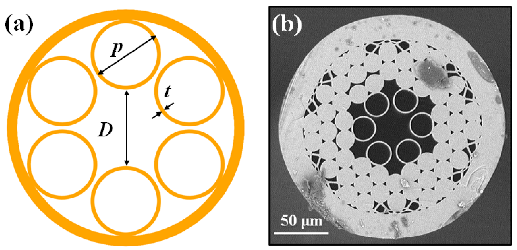
As depicted in Figure 1a, the HC-ARF is composed of one layer of capillaries that surrounds the hollow region to form an anti-resonant guidance. The nodeless cladding and negative curvature of the core-cladding boundary are two critical features of HC-ARF that significantly reduce the fiber loss [13,27,28]. The HC-ARF fabricated by the stack and draw technique [9,29] has a good structure, as presented in Figure 1b. Among all the geometric parameters, the most important parameters are core diameter D, capillary size p and capillary wall thickness t. While both D and p relate to the fiber loss, t is the only geometric parameter that determines the transmission wavelengths. Transmission bands of HC-ARFs are determined by the resonant wavelengths. Resonant wavelengths are the central wavelength of high loss regions, and a low loss transmission band exists between every adjacent high loss region. The m-th order resonant wavelength, , can be calculated from the following equation [30]:
where t is the wall thickness, is the refractive index of cladding material and is the refractive index of core material. In the case of silica-based air core fiber, we set and . The low loss region between the m-th and -th resonant wavelengths is called the m-th transmission band.
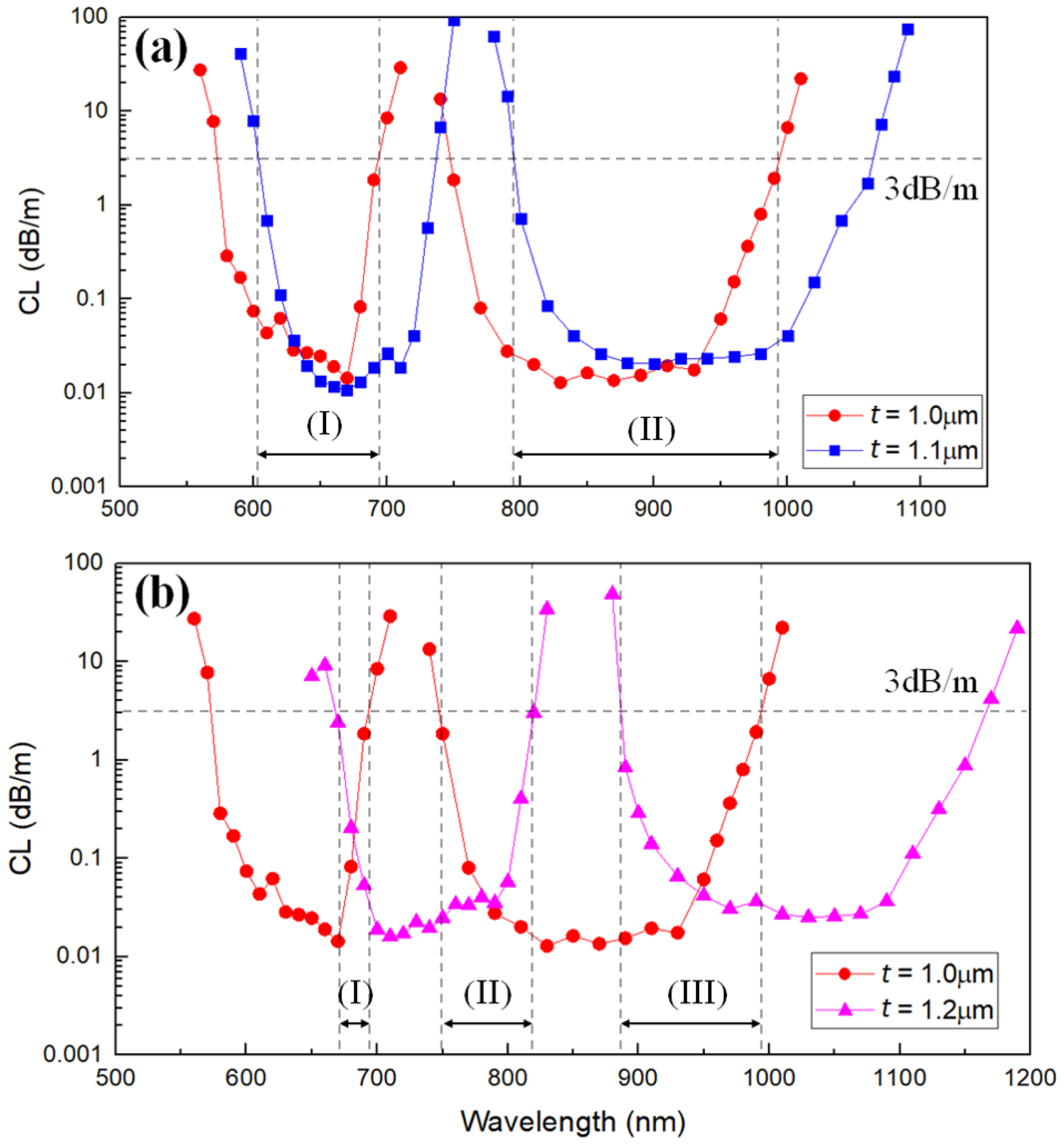
The second and third transmission bands of HC-ARFs with different wall thicknesses are studied by simulation. The results are calculated by a vector wave expansion method using the open source software Polymode [31]. As shown in Figure 2a, combing a fiber ( µm) to another fiber possessing a thicker wall ( µm) leads to the narrowing of transmission bands. We define the transmission band when its CL is below 3 dB/m. If the wall thickness difference between the fibers becomes larger (e.g., µm and µm), the -th transmission band of the thick-wall fiber can overlap with the m-th transmission band of the thin-wall fiber, resulting in multiple and narrow transmission bands (see Figure 2b).
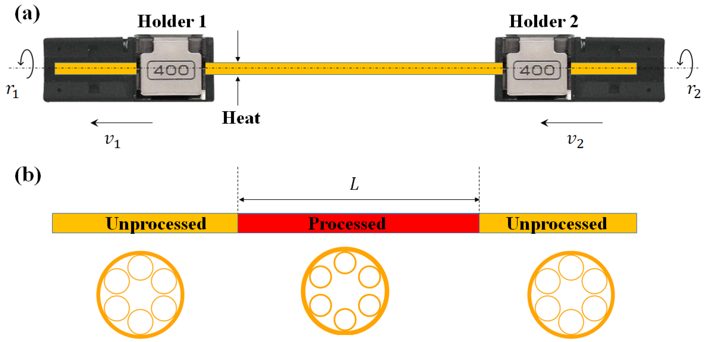
Although combing HC-ARFs with different t can narrow the transmission bands, it is inefficient and troublesome to fabricate multiple HC-ARFs with different wall thicknesses and to splice them together. Instead, it makes more sense to process a piece of uniform fiber to have varied wall thicknesses along its axis. To achieve this, a CO2 laser-assisted glass processing stage (LZM-100 from Fujikura Ltd., Tokyo, Japan) is used to process the fiber. As illustrated in Figure 3a, a piece of HC-ARF is loaded onto two fiber holders. During the fiber processing, both holders rotate at the same speed to ensure symmetric heating. In parallel, the holders longitudinally move at the same traveling speed toward the same direction in order to avoid any twist or stretch. A section of the HC-ARF is locally heated by the CO2 laser with tunable power P. Under the CO2 laser treatment, the exposed section undergoes shrinkage due to surface tension, resulting in increasing wall thickness. The wall thickness of the processed fiber is controllable by adjusting the laser power P. Hence, uniform modification of wall thickness is achievable by moving the laser exposure along the fiber axis, as illustrated in Figure 3b.
3. Results and Discussion
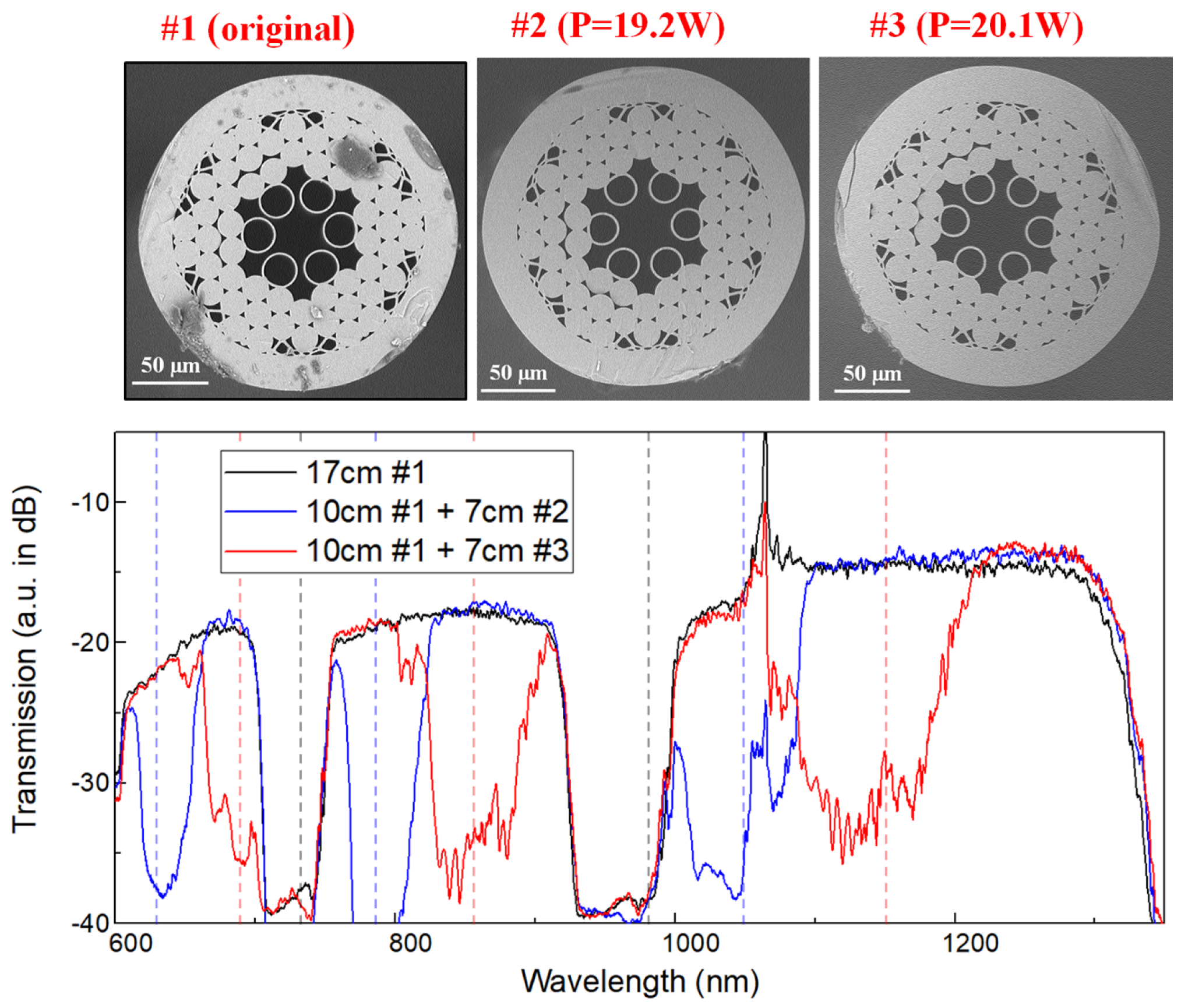
A 17-cm HC-ARF, Fiber #1 (please, see Figure 4), was processed with the aforementioned method under different heating powers. The original fiber (Fiber #1) had a wall thickness µm and a core diameter µm, while the wall thickness of the processed fiber increased to be 1.49 µm (Fiber #2, processed with 19.2 W of heating power) and 1.63 µm (Fiber #3, processed with 20.1 W of heating power), respectively. As predicted, under high temperature, capillaries shrunk to induce a thicker wall due to surface tension. Transmission spectra of different fiber combinations were also measured, as shown in Figure 4. Resonant wavelengths of Fiber #2 and Fiber #3 were calculated and marked with blue and red dashed lines, respectively. As demonstrated by the measured transmission spectra, writing a new fiber on the original fiber by the CO2 laser introduced a new high loss region (extra resonant band), realizing a selective transmission/rejection in-fiber filter. We noticed that the writing process did not introduce any significant extra loss. Besides the controllability, the reproducibility of the proposed method was also verified as the fibers processed under the same CO2 laser power showed similar transmission spectra.
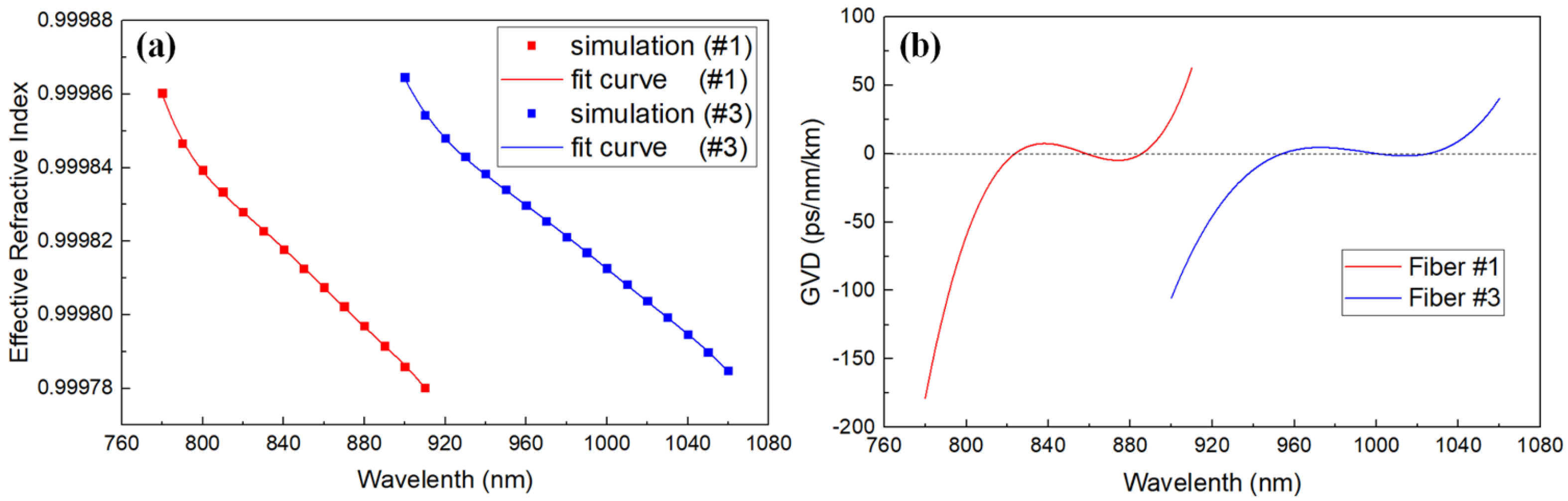
More interestingly, as both t and D were changed, the dispersion curve of the fiber significantly shifted. As shown in Figure 5a, the Effective Refractive Index (ERI) curves were obtained by fitting the simulation values (solid dots), then the Group Velocity Dispersion (GVD) curves were calculated from the ERI curves, as shown in Figure 5b. As the fiber structure was changed from #1–#3, the zero dispersion wavelength shifted from around 860 nm to around 1000 nm. The change of the core size was responsible for this dispersion curve transformation [4]. Therefore, the proposed method also has promising prospects in applications relying on dispersion control, especially in pulse compression.
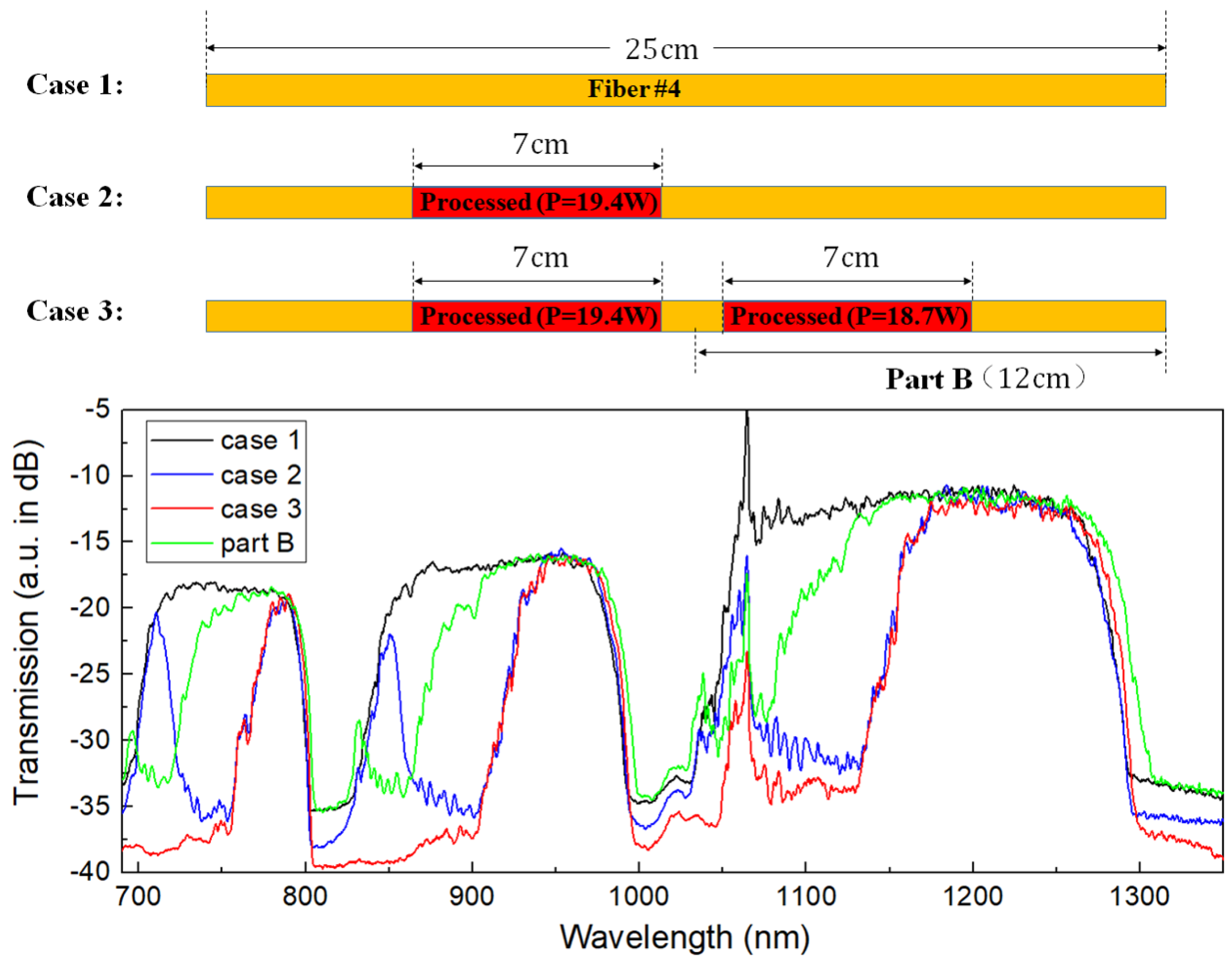
The method is also applicable to a multiple layer HC-ARF, as evidenced by the results in Figure 6. The two-layer structure responded to the CO2 laser writing process to introduce an additional rejection band. As indicated in both Figure 4 and Figure 6, implementing a new single different wall thickness for an existing HC-ARF can made band reject filters. Here, we also demonstrate a band pass filter by introducing multiple different wall thicknesses into an original HC-ARF. The procedure is described in Figure 7. We used a two-layer HC-ARF as a pristine fiber. A section of 7 cm in the 25 cm-long pristine fiber (Fiber #4) was written under exposure power P = 19.4 W. Its corresponding transmission is present in the blue curve in Figure 7. Subsequently, another section of the same length was written by the lower power of P = 18.7 W to decrease the number of transmission bands (red line in Figure 7). The final fiber had limited transmission bands and worked more like a band pass filter with low excess loss, but 20-dB high extinction ratio.
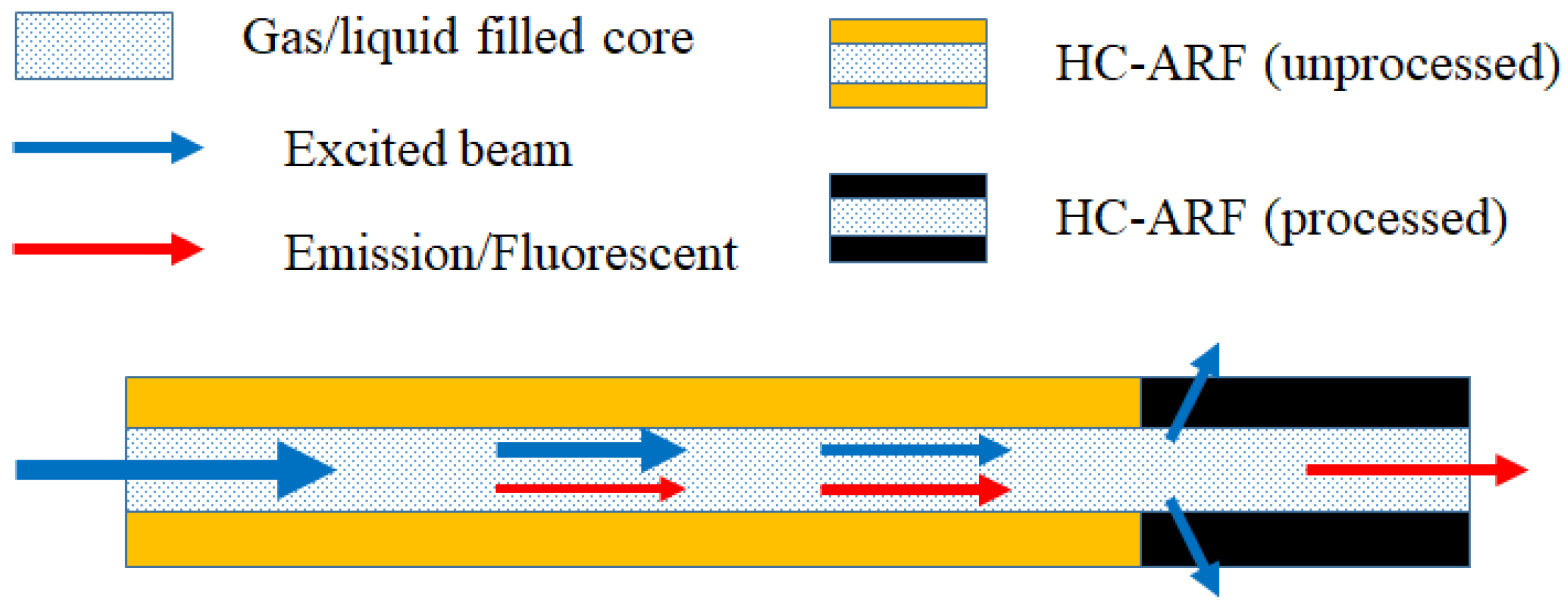
The demonstrated HC-ARF-based filter could find interesting applications such as pump and signal wavelength separation in a gas-/liquid-filled HC-ARF system. HC-ARFs have been adopted to demonstrate excellent cavities for gas Raman generation and optofluidic systems [19,20] in which for both cases, free space optical filters were selected to filter out the excitation beam. Alternatively, by simply processing the HC-ARF with the method proposed in this work, an HC-ARF-based optical filter can be seamlessly written into the system without extra loss, as illustrated in Figure 8. This would be one step closer to an all-fiberized hollow core fiber system.
4. Conclusions
HC-ARFs with uniform wall thickness thave multiple and broad transmission bands. We have shown that writing a different wall thickness HC-ARF is feasible by using a CO2 laser-based glass process stage. Consequently, the written HC-ARF exhibits the AND operation of two transmission characteristics defined by the written and the pristine HC-ARFs’ wall thicknesses. In addition, we demonstrated multiple chained AND operations by writing various wall thickness HC-ARFs in series along the fiber axis. On the basis of this principle, a novel method has also been proposed and demonstrated to convert HC-ARFs into in-fiber filters. The HC-ARF filter fabricated by this method benefits from low excess loss, easy integration with the HC-ARF-based system and controllable transmission/rejection wavelengths. We have also suggested a potential application of such fiber filters toward an all-fiberized HC-ARF system.
Author Contributions
X.H. conceived of the idea, performed the experiments, analyzed the data and wrote the manuscript. S.Y. supervised the design of the study and revised the manuscript. K.-T.Y supervised the design and participated in the experimental setup.
Funding
This research received no external funding.
Acknowledgments
S.Y. acknowledges support from KEIP through the Global Research Programme.
Conflicts of Interest
The authors declare no conflict of interest.
Abbreviations
The following abbreviations are used in this manuscript:
| HC-PCF | Hollow-Core Photonic Crystal Fiber |
| HC-PBGF | Hollow-Core Photonic Bandgap Fiber |
| HC-ARF | Hollow-Core Anti-Resonant Fiber |
| ERI | Effective Refractive Index |
| GVD | Group Velocity Dispersion |
References
- Birks, T.A.; Roberts, P.J.; Russell, P.S.J.; Atkin, D.M.; Shepherd, T.J. Full 2-D photonic bandgaps in silica/air structures. Electron. Lett. 1995, 31, 1941–1943. [Google Scholar] [CrossRef]
- Smith, C.M.; Venkataraman, N.; Gallagher, M.T.; Müller, D.; West, J.A.; Borrelli, N.F.; Allan, D.C.; Koch, K.W. Low-loss hollow-core silica/air photonic bandgap fibre. Nature 2003, 424, 657–659. [Google Scholar] [CrossRef] [PubMed]
- Jaworski, P.; Yu, F.; Carter, R.M.; Knight, J.C.; Shephard, J.D.; Hand, D.P. High energy green nanosecond and picosecond pulse delivery through a negative curvature fiber for precision micro-machining. Opt. Express 2015, 23, 8498–8506. [Google Scholar] [CrossRef] [PubMed]
- Gérôme, F.; Cook, K.; George, A.K.; Wadsworth, W.J.; Knight, J.C. Delivery of sub-100fs pulses through 8 m of hollow-core fiber using soliton compression. Opt. Express 2007, 15, 7126–7131. [Google Scholar] [CrossRef] [PubMed]
- Poletti, F.; Wheeler, N.V.; Petrovich, M.N.; Baddela, N.; Fokoua, E.N.; Hayes, J.R.; Gray, D.R.; Li, Z.; Slavík, R.; Richardson, D.J. Towards high-capacity fibre-optic communications at the speed of light in vacuum. Nat. Photonics 2013, 7, 279–284. [Google Scholar] [CrossRef]
- Roberts, P.J.; Couny, F.; Sabert, H.; Mangan, B.J.; Williams, D.P.; Farr, L.; Mason, M.W.; Tomlinson, A.; Birks, T.A.; Knight, J.C.; et al. Ultimate low loss of hollow-core photonic crystal fibres. Opt. Express 2005, 13, 236–244. [Google Scholar] [CrossRef] [PubMed]
- Couny, F.; Benabid, F.; Roberts, P.J.; Light, P.S.; Raymer, M.G. Generation and photonic guidance of multi-octave opticalfrequency combs. Science 2007, 318, 1118–1121. [Google Scholar] [CrossRef] [PubMed]
- Gao, S.F.; Wang, Y.Y.; Ding, W.; Jiang, D.L.; Gu, S.; Zhang, X.; Wang, P. Hollow-core conjoined-tube negative-curvature fibre with ultralow loss. Nat. Common. 2018, 9, 2828. [Google Scholar] [CrossRef] [PubMed]
- Huang, X.; Yoo, S.; Yong, K. Function of second cladding layer in hollow core tube lattice fibers. Sci. Rep. 2017, 7, 1618. [Google Scholar] [CrossRef] [PubMed]
- Poletti, F. Nested anti-resonant nodeless hollow core fiber. Opt. Express 2014, 22, 23807–23828. [Google Scholar] [CrossRef] [PubMed]
- Yu, F.; Knight, J.C. Negative curvature hollow core optical fiber. IEEE J. Sel. Top. Quantum Electron. 2016, 22, 4400610. [Google Scholar] [CrossRef]
- Huang, X.; Qi, W.; Ho, D.; Yong, K.T.; Luan, F.; Yoo, S. Hollow core anti-resonant fiber with split cladding. Opt. Express 2016, 24, 7670–7678. [Google Scholar] [CrossRef] [PubMed]
- Belardi, W.; Knight, J.C. Effect of core boundary curvature on the confinement losses of hollow anti-resonant fibers. Opt. Express 2013, 21, 21912–21917. [Google Scholar] [CrossRef] [PubMed]
- Hayes, J.R.; Sandoghchi, S.R.; Bradley, T.D.; Liu, Z.; Slavík, R.; Gouveia, M.A.; Wheeler, N.V.; Jasion, G.; Chen, Y.; Fokoua, E.N.; et al. Antiresonant hollow core fiber with an octave spanning bandwidth for short haul data communications. J. Lightwave Technol. 2017, 35, 437–442. [Google Scholar] [CrossRef]
- Debord, B.; Amsanpally, A.; Chafer, M.; Baz, A.; Maurel, M.; Blondy, J.; Hugonnot, E.; Scol, F.; Vincetti, L.; Gérôme, F.; et al. Ultralow transmission loss in inhibited-coupling guiding hollow fibers. Optica 2017, 4, 209–217. [Google Scholar] [CrossRef]
- Belardi, W.; Knight, J.C. Hollow anti-resonant fibers with reduced attenuation. Opt. Lett. 2014, 39, 1853–1856. [Google Scholar] [CrossRef] [PubMed]
- Gao, S.F.; Wang, Y.Y.; Ding, W.; Wang, P. Hollow-core negative-curvature fiber for UV guidance. Opt. Lett. 2018, 43, 1347–1350. [Google Scholar] [CrossRef] [PubMed]
- Yu, F.; Wadsworth, W.J.; Knight, J.C. Low loss silica hollow core fibers for 3–4 µm spectral region. Opt. Express 2012, 20, 11153–11158. [Google Scholar] [CrossRef] [PubMed]
- Liu, X.L.; Ding, W.; Wang, Y.Y.; Gao, S.F.; Cao, L.; Feng, X.; Wang, P. Characterization of a liquid-filled nodeless anti-resonant fiber for biochemical sensing. Opt. Lett. 2012, 42, 863–866. [Google Scholar] [CrossRef] [PubMed]
- Williams, G.O.; Euser, T.G.; Arlt, J.; Russell, P.S.J.; Jones, A.C. Hollow anti-resonant fibers with reduced attenuation. ACS Photonics 2014, 1, 790–793. [Google Scholar] [CrossRef]
- Russell, P.S.J.; Hölzer, P.; Chang, W.; Abdolvand, A.; Travers, J.C. Hollow-core photonic crystal fibres for gas-based nonlinear optics. Nat. Photonics 2014, 8, 278–286. [Google Scholar] [CrossRef]
- Huang, X.; Ma, J.; Tang, D.; Yoo, S. Hollow-core air-gap anti-resonant fiber couplers. Opt. Express 2017, 25, 29296–29306. [Google Scholar] [CrossRef]
- Liu, X.; Fan, Z.; Shi, Z.; Ma, Y.; Yu, J.; Zhang, J. Dual-core anti-resonant hollow core fibers. Opt. Express 2016, 24, 17453–17458. [Google Scholar] [CrossRef] [PubMed]
- Argyros, A.; Leon-Saval, S.G.; van Eijkelenborg, M.A. Twin-hollow-core optical fibres. Opt. Commun. 2009, 282, 1785–1788. [Google Scholar] [CrossRef]
- Ouellette, F. All-fiber filter for efficient dispersion compensation. Opt. Lett. 1991, 16, 303–305. [Google Scholar] [CrossRef] [PubMed]
- Antonio-Lopez, J.E.; Castillo-Guzman, A.; May-Arrioja, D.A.; Selvas-Aguilar, R.; LiKamWa, P. Tunable multimode-interference bandpass fiber filter. Opt. Lett. 2010, 35, 324–326. [Google Scholar] [CrossRef] [PubMed]
- Pryamikov, A.D.; Biriukov, A.S.; Kosolapov, A.F.; Plotnichenko, V.G.; Semjonov, S.L.; Dianov, E.M. Demonstration of a waveguide regime for a silica hollow-core microstructured optical fiber with a negative curvature of the core boundary in the spectral region >3.5 µm. Opt. Express 2011, 19, 1441–1448. [Google Scholar] [CrossRef] [PubMed]
- Kolyadin, A.N.; Kosolapov, A.F.; Pryamikov, A.D.; Biriukov, A.S.; Plotnichenko, V.G.; Dianov, E.M. Light transmission in negative curvature hollow core fiber in extremely high material loss region. Opt. Express 2013, 21, 9514–9519. [Google Scholar] [CrossRef] [PubMed]
- KolBrilland, L.; Smektala, F.; Renversez, G.; Chartier, T.; Troles, J.; Nguyen, T.N.; Traynor, N.; Monteville, A. Fabrication of complex structures of Holey Fibers in Chalcogenide glass. Opt. Express 2006, 14, 1280–1285. [Google Scholar] [CrossRef]
- Litchinitser, N.M.; Dunn, S.C.; Usner, B.; Eggleton, B.J.; White, T.P.; McPhedran, R.C.; de Sterke, C.M. Resonances in microstructured optical waveguides. Opt. Express 2003, 11, 1243–1251. [Google Scholar] [CrossRef] [PubMed]
- Issa, N.A.; Poladian, L. Vector wave expansion method for leaky modes of microstructured optical fibers. J. Lightwave Technol. 2003, 21, 1005–1012. [Google Scholar] [CrossRef]
Figure 1.
(a) Schematic diagram of the cross-sectional view of a negative curvature HC-ARF (Hollow-Core Anti-Resonant Fiber). t is the capillary wall thickness; p is the capillary outer diameter; and D is the core diameter. (b) HC-ARF fabricated by the stack and draw method that produces a good structure.

Figure 2.
Simulated second and third transmission bands of HC-ARFs with different t. Roman numerals mark the hybrid transmission bands of HC-ARFs with: (a) µm and µm; (b) µm and µm. In all cases, µm, µm.
Figure 2.
Simulated second and third transmission bands of HC-ARFs with different t. Roman numerals mark the hybrid transmission bands of HC-ARFs with: (a) µm and µm; (b) µm and µm. In all cases, µm, µm.

Figure 3.
(a) Schematic diagram of the HC-ARF processing, rpm, µm/ms; heating is realized with a CO2 laser. (b) During the process, the HC-ARF undergoes structural deformation, yielding a thicker wall. L is the length of the processed fiber.
Figure 3.
(a) Schematic diagram of the HC-ARF processing, rpm, µm/ms; heating is realized with a CO2 laser. (b) During the process, the HC-ARF undergoes structural deformation, yielding a thicker wall. L is the length of the processed fiber.

Figure 4.
Transmission spectra of different fiber combinations. Fiber #1: unprocessed fiber, µm, µm; Fiber #2: processed under W, µm, µm; Fiber #3: processed under W, µm, µm. Resonant wavelengths of Fiber #1, Fiber #2 and Fiber #3 are calculated from Equation (1) and marked with dashed black lines, dashed blue lines and dashed red lines respectively.

Figure 5.
(a) Effective refractive index and (b) GVD (Group Velocity Dispersion) curve of both Fiber #1 and #3. In (a), the dots plot the simulation values, while the solid curves are quintic functions, which fit the simulation values.
Figure 5.
(a) Effective refractive index and (b) GVD (Group Velocity Dispersion) curve of both Fiber #1 and #3. In (a), the dots plot the simulation values, while the solid curves are quintic functions, which fit the simulation values.

Figure 6.
Transmission spectra of different fiber combinations. Fiber #4: unprocessed fiber, µm; Fiber #5: processed under W, µm; Fiber #6: processed under W, µm.
Figure 6.
Transmission spectra of different fiber combinations. Fiber #4: unprocessed fiber, µm; Fiber #5: processed under W, µm; Fiber #6: processed under W, µm.

Figure 7.
Schematic diagram illustrating the steps to make an HC-ARF-based band pass filter. As multiple different wall thicknesses are “written” into the original HC-ARF, the transmission bands are greatly narrowed.
Figure 7.
Schematic diagram illustrating the steps to make an HC-ARF-based band pass filter. As multiple different wall thicknesses are “written” into the original HC-ARF, the transmission bands are greatly narrowed.

Figure 8.
This schematic diagram shows the working principle of the HC-ARF-based filter in gas-/liquid-filled optical systems.
Figure 8.
This schematic diagram shows the working principle of the HC-ARF-based filter in gas-/liquid-filled optical systems.

© 2018 by the authors. Licensee MDPI, Basel, Switzerland. This article is an open access article distributed under the terms and conditions of the Creative Commons Attribution (CC BY) license (http://creativecommons.org/licenses/by/4.0/).
Share and Cite
MDPI and ACS Style
Huang, X.; Yong, K.-T.; Yoo, S. A Method to Process Hollow-Core Anti-Resonant Fibers into Fiber Filters. Fibers 2018, 6, 89. https://0-doi-org.brum.beds.ac.uk/10.3390/fib6040089
AMA Style
Huang X, Yong K-T, Yoo S. A Method to Process Hollow-Core Anti-Resonant Fibers into Fiber Filters. Fibers. 2018; 6(4):89. https://0-doi-org.brum.beds.ac.uk/10.3390/fib6040089
Chicago/Turabian StyleHuang, Xiaosheng, Ken-Tye Yong, and Seongwoo Yoo. 2018. "A Method to Process Hollow-Core Anti-Resonant Fibers into Fiber Filters" Fibers 6, no. 4: 89. https://0-doi-org.brum.beds.ac.uk/10.3390/fib6040089
Note that from the first issue of 2016, this journal uses article numbers instead of page numbers. See further details here.