Conductive Regenerated Cellulose Fibers by Electroless Plating
by
 , , ,
, , ,
Zainab Al-Maqdasi
1,* ,
,
Abdelghani Hajlane
2,*,
Abdelghani Renbi
3,
Ayoub Ouarga
2,
Shailesh Singh Chouhan
3 and
Roberts Joffe
1 1
Department of Engineering Sciences and Mathematics, Luleå University of Technology, 97187 Luleå, Sweden
2
Materials Science and Nano-engineering, Mohammed VI Polytechnic University, Benguerir 43150, Morocco
3
Department of Computer Science, Electrical and Space Engineering, Luleå University of Technology, 97187 Luleå, Sweden
*
Authors to whom correspondence should be addressed.
Fibers 2019, 7(5), 38; https://0-doi-org.brum.beds.ac.uk/10.3390/fib7050038
Submission received: 3 April 2019
/
Revised: 18 April 2019
/
Accepted: 23 April 2019
/
Published: 1 May 2019
Abstract
:Continuous metalized regenerated cellulose fibers for advanced applications (e.g., multi-functional composites) are produced by electroless copper plating. Copper is successfully deposited on the surface of cellulose fibers using commercial cyanide-free electroless copper plating packages commonly available for the manufacturing of printed wiring boards. The deposited copper was found to enhance the thermal stability, electrical conductivity and resistance to moisture uptake of the fibers. On the other hand, the chemistry involved in plating altered the molecular structure of the fibers, as was indicated by the degradation of their mechanical performance (tensile strength and modulus).
1. Introduction
Regenerated cellulose fibers (RCFs) are man-made fibers from naturally occurring cellulose that is spun-formed into continuous, uniform cross-sectional fibers with rather stable physical properties [1]. When compared with natural plant fibers, the properties of RCFs are more application-tunable and less dependent on the cellulose source or the growing–cultivation conditions. Considering their natural origin and end-of-life disposal, the latest generations of these fibers are more environmentally friendly than the conventional fibers [2,3] used in composites (e.g., glass, carbon) or in textiles (e.g., polyester, polyamide). RCFs are commercially available and are used in various applications with increasing interest in the research and development sectors to improve their performance for use in composites as a reinforcement [4]. In order for these materials to be used in advanced applications, however, not only does their mechanical performance need to be improved, but the addition of new functionalities has also become essential. This can boost their potential limits and suitability for a wider range of applications.
Wearable electronics and electronic casings are examples of applications where electrically conductive functional fabrics are in high demand. The design of conductive cellulose fibers has been approached differently by researchers, for example via the incorporation of graphene during the spinning process of the fiber production [5], or dip-coating the fibers with carbon nanotubes [6]. However, a simpler and more convenient way to achieve conductivity is the use of electroless metal plating on the surface of the fibers. The use of electroless plating to produce conductive cellulose fibers has been reported in the literature, for example in the deposition of a thin layer of copper for microwave applications [7], and in the coating of ferromagnetic material to produce ferromagnetic cellulose microfibers [8] for various electronics applications. Electroless metal coating is very simple and matured process for various applications, such as printed electronics. However, experimental parameters such as the temperature, concentration, and pH of the involved chemistry have a great influence on the properties of the substrate-fibers and the quality of the coating [9]. The reason for this is that the chemical treatment not only modifies the surface but also alters the chemical structure of the cellulose fibers [10]. Recent studies used the approach to produce copper conductive layers on non–conductive lyocell fabrics. This involved preliminary surface activation through silver seeding and bath composition containing HCHO and C4H5KO6 at different concentrations [11]. Despite the resulting overall conductive fabric, the risk of losing connectivity at the crossover points between the wrap and the weft is the primary disadvantage of coating fabric rather than individual bundles.
Moreover, the abovementioned and other studies have presented the possibility of coating RCFs with copper to make them conductive, but none of them have addressed the effect of the electroless plating process on their mechanical performance. Thus, this paper studies copper-coated RCFs produced using the electroless process, along with evaluating the effect of different immersion times in a Cu-plating bath on the electrical and mechanical properties of the fibers, including the quality of the coating. The process might be directly incorporated in the production of weaves to make conductive fabric on an industrial scale.
2. Materials and Methods
Bundles of regenerated cellulose fibers (Cordenka 700 Super 3 from Cordenka GmbH, Obernburg, Germany) of 50 mm length were used in this study. The fibers have a semi-circular cross-section of diameter about 12.5 µm. The chemicals used for the electroless plating (perfekto-PEC660) were commercially available solutions from JKEM international, Sweden. Such packages are well known to be optimized for better conductivity, deposited thickness, and adhesion for specific substrate materials.
2.1. Fiber Plating
The process consisted of four main steps in the following sequence: First, the fibers were dipped in a 1:4 Pre DIP Alkaline Catalyst System (ACS) 73 to de-ionized water solution at a pH of 11–12 for 1 min at 25 °C. Second, they were treated in a bath of 1:4 parts of catalyst ACS 74 to de-ionized water at a pH of 11.5–12.5 for 5 min at 40 °C, followed by two washes with de-ionized water for 1 min per wash. Then, a reducing bath containing 0.5 L reducer ACS 75, 98 L deionized water and a 2 Kg of Boric acid was used at 25–30 °C and a regulated pH of 7 into which the fibers were immersed for 0.5 to 1 min and washed twice with deionized water for 1 min each time. In the last step, a copper-plating solution bath was made up with Perfekto Electroless Copper (PEC) 660 components and de-ionized water in the following ratios: 80 de-ionized water, 7.5 PEC 660 A, 5 PEC 660 M, 8 PEC 660 B with the mentioned sequence and accompanied by continuous agitation. The immersion time in the last bath was varied: 15, 30, 45, 60, and 90 min.
2.2. Characterization
Microscopy on individual fibers and cross-sections of bundles was performed using a Nikon Eclipse MA200 optical microscope (OM) (Nikon Corporation, Tokyo, Japan) and JEOL JCM-6000 Neoscope scanning electron microscope (SEM) (JEOL technics LTD, Tokyo, Japan). Coated bundles were mounted in an epoxy resin, polished, and their cross-section was investigated. Analysis of the area fraction was performed by separating the components into fractions based on the color contrast. The coating thickness was determined by selecting a coated fiber randomly and averaging the measured thickness at eight radial points. The thickness at the points where the coating was missing was set to zero. The maximum thickness was also based on this random selection and may not represent the actual maximum thickness.
Single fiber tensile tests on 20 mm long fibers were performed to evaluate the mechanical properties. These tests were done on an Instron 4411 universal testing machine equipped with a 5 N load cell and pneumatic grips. Tensile tests were carried out in a displacement-controlled mode with a loading rate of 2 mm/min (corresponding to a strain rate of 10%/min). The strain was calculated from the displacement of the crosshead of the machine taking into account the system compliance with respect to uncoated fibers (UCF). Following the guidelines of the ASTM D3822/D3822M standard, individual fibers, selected randomly from the coated bundles and reference UCF, were carefully separated and glued on paper frames. These frames were cut prior to starting the test. Some fibers broke during mounting on the frames, which may skew the results towards higher strength values. A set of minimum 7 fibers were tested, and the average values are presented.
Fourier-transform infrared (FTIR) (PerkinElmer Inc, Waltham, MA, USA) spectra in attenuated total reflectance (ATR) mode were collected on uncoated and surface copper coated cellulose fibers to detect new absorption bands, if any, during chemical modification. For sample preparation, fibers were cut to be 1 cm long and then analyzed using Perkin Elmer FT-IR Spectrometer. The spectra were recorded after 32 scans with a resolution of 4 cm−1 within the range of 4000–700 cm−1.
Thermo-gravimetric analysis (TGA) (Discovery TGA, TA Instruments Inc, New Castel, DE, USA) was used to evaluate the degradation characteristics of the fibers under a controlled temperature program. Thermo-gravimetric analyzer TGA 5500 was employed to heat from 20–500 °C, at a heating rate of 10 °C/min in nitrogen as carrier gas with flow rate of 30 ml/min.
Electrical resistance measurements of bundles and single fibers were performed at room temperature by 4-wire method using a high precision Fluke 8840A multi-meter (Fluke Corporation, Everett, WA, USA). To ease the probing, all measured samples were adjusted to be 50 mm long. Later, measurements were confirmed using the programmable LCR Bridge HM8118 by Hameg instruments (Hameg Instruments, Frankfurt, Germany).
3. Results and Discussion
3.1. Microscopy
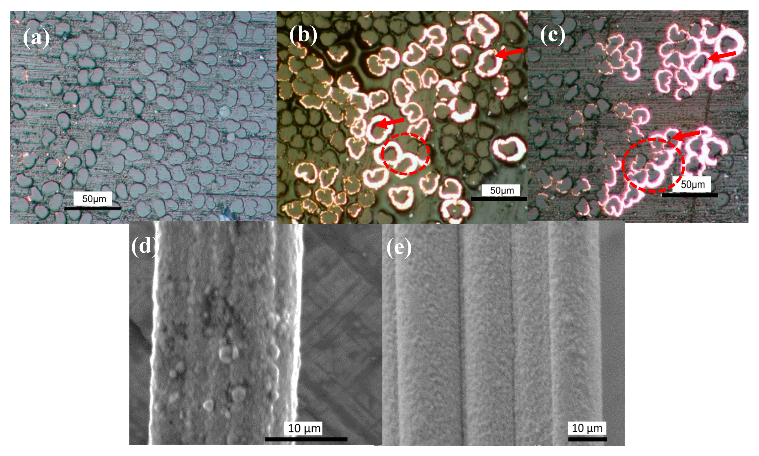
Figure 1 shows OM and SEM images of selected samples. Figure 1a of the sample plated for 15 min shows that copper was deposited only at some points at the outermost fibers of the bundle. It could also be seen that although the coating on samples with longer immersion times (Figure 1b,c) reproduced the shape of the fiber, the layer of copper was not uniform around the fiber contour. Thus, inhomogeneity could be seen within the coating along an individual fiber as well as in between fibers within the bundle. However, it was concluded that as the immersion time increased, more copper could be successfully deposited on the fiber (see Figure S1 in the supplementary materials for images of the whole bundles). The SEM micrographs show that for a shorter immersion time, the copper particles form a discontinuous layer on the fibers, but due to the inhomogeneity it was not possible to find a representative image for the 15 min or 45 min samples. This is indicated in the supplementary materials (Figure S2). The coating, however, appeared continuous and denser for 60 min and onwards (Figure 1d,e). On the other hand, for the higher deposition time (90 min), the change in thickness and quality of the copper on the fibers was not noticeable, although the number of coated fibers increased.
Systematic measurements of the coating thickness performed on optical micrographs of randomly-selected coated fibers revealed a lower average thickness of the coating in the 90 min sample (2.72 ± 1.19 µm) than that of the 60 min sample (3.41 ± 1.31 µm), but no significant difference in the maximum measured thickness (7.92 vs. 8.03 µm for 60 min and 90 min, respectively). At the same time, the ratio between the area occupied by the copper and fibers on optical micrographs showed a considerable difference at 90 min when compared to the 60 min immersion time (20% and 8%, respectively). This means that the longer immersion time does not necessarily increase the coating thickness, but it might lead to deeper penetration of copper inside the bundle covering larger surface areas or forming bridges between the coated fibers, bonding them together. This was noticed at several instances during the SEM and OM observations (see the dashed ovals on the OM images of Figure 1). Arrows in Figure 1 point at some areas with imperfect copper/fiber bond. This de-bonding probably occurred during handling of the fibers after coating. This might influence the mechanical properties and the electrical conductivity of the fibers. Further investigations by micro-bond test would help to assess the strength of the fiber–coating and coating–matrix adhesion.
3.2. Electrical Properties
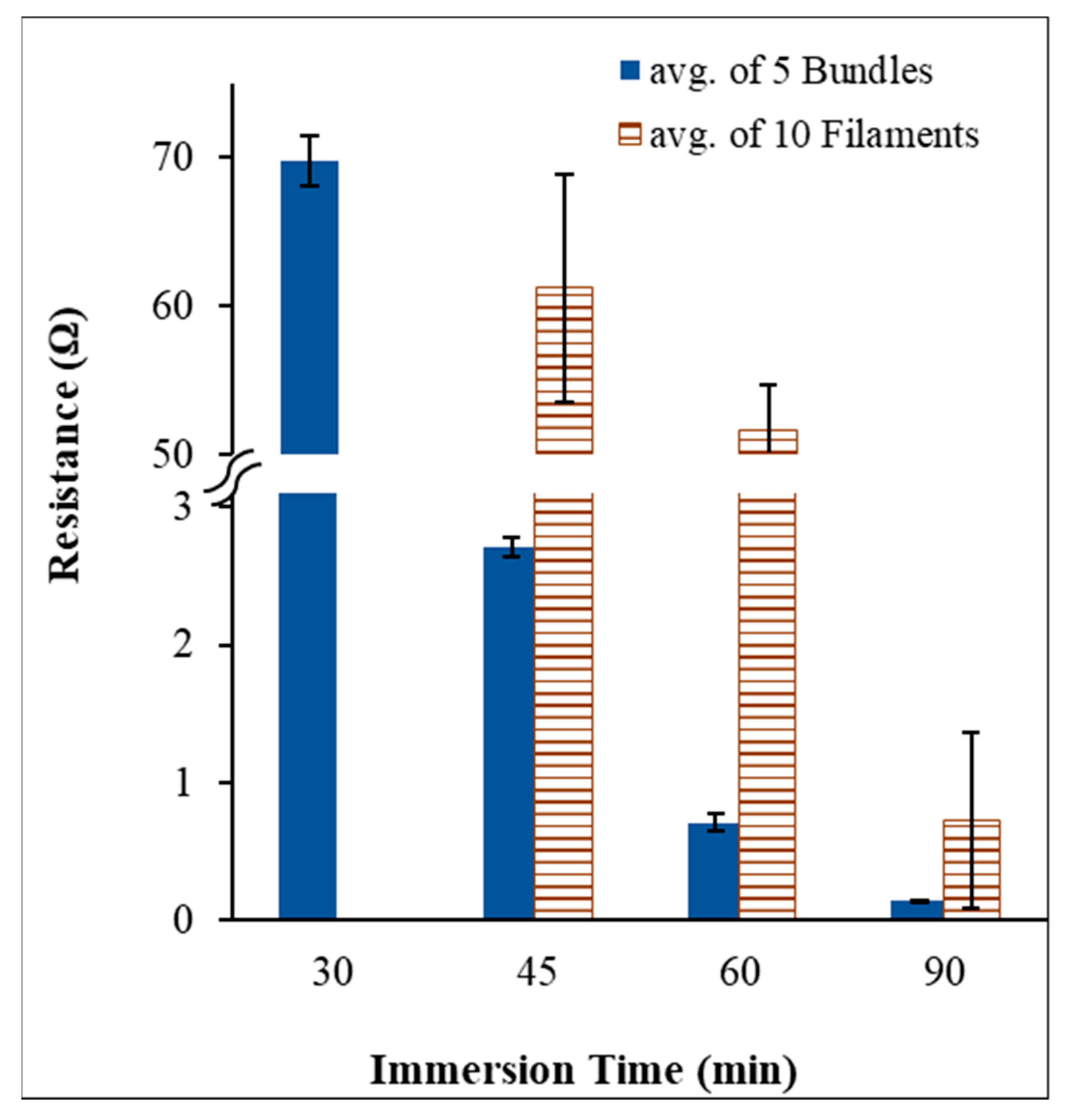
Measurement of the electrical resistance on bundles rather than on individual fibers is more practical and relevant to the application of fibers in composites, since the final product (textiles and composites) would be made of bundles rather than single filaments. This is also evident from the graphs in Figure 2, since the resistance of the bundles compared to single filaments was always lower for the same immersion time. According to the experiments, the immersion time of 15 min only led to measured resistance in the MΩ ranges, thus the bundles practically remained non-conductive. In such cases, samples have always resulted in matt surfaces as shown in Figure S3. However, the conductivity continued to increase by increasing the immersion time. This supports the claim of having new contact points from the larger surface area of the deposited copper, which is likely to penetrate deeper into the bundle.
3.3. Mechanical Properties
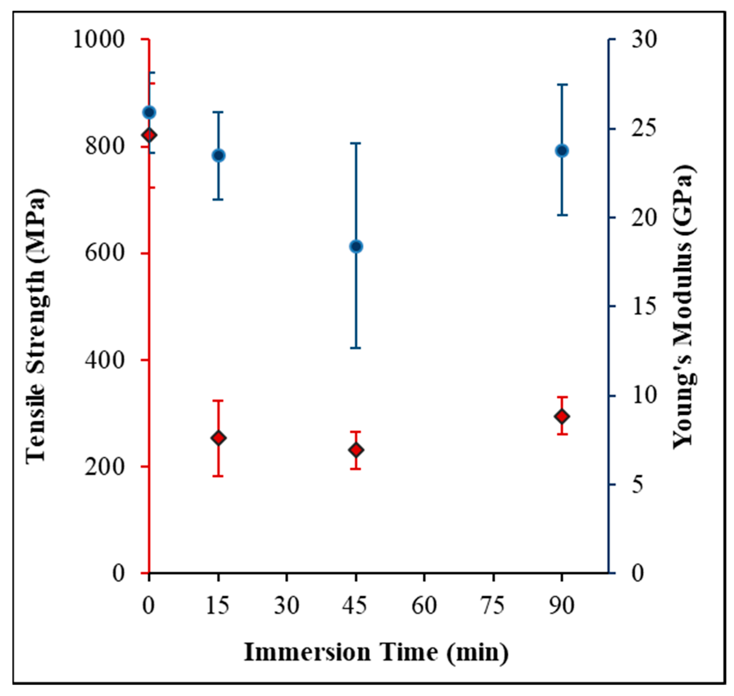
Due to the limited amount of sample, and seeking a proof of concept, the mechanical properties were investigated on individual fibers rather than on bundles. Figure 3 shows the mechanical properties of the UCF and coated fibers for different Cu-plating times. The tensile properties of the fibers have been largely degraded. Stiffness and strength of the single fibers for the 15 min immersion time decreased by around 10% and 70% respectively when compared with UCF. It is possible that exposing the fibers to chemicals in the plating process causes relaxation of the molecules leading to a loss of orientation and disorder in the fiber microstructure [12]. The orientation of the cellulose chains is responsible for its mechanical performance and is attained during the manufacturing process by stretching the fibers along the axial direction. It is reasonable then, to consider that if these chains are allowed to relax by any external factor, they tend to form a more amorphous structure and lose their orientation, leading to reduced mechanical performance. Copper, on the other hand, is a rigid metal compared to the soft fibers (the stiffness of copper is estimated around 128 GPa [13]) and its presence on the surface of the fibers is responsible for increasing their stiffness and compensate for the stiffness lost during the chemical treatment. However, due to its brittleness it does not contribute to the strength. This was further investigated by FTIR analysis. However, no significant difference is noticed in the strength of the samples at different immersion times, indicating that the degradation occurred either during the fiber-surface-activation process or immediately after immersion in the copper-plating bath. To confirm this statement, additional investigation should be carried out. After 90 min immersion time, the fibers seem to retain some of their properties, since the stiffness loss was only 8%. As mentioned above, this is possibly due to the support provided by the large amount of copper deposited on the fibers.
3.4. Spectral and Gravimetric Analysis
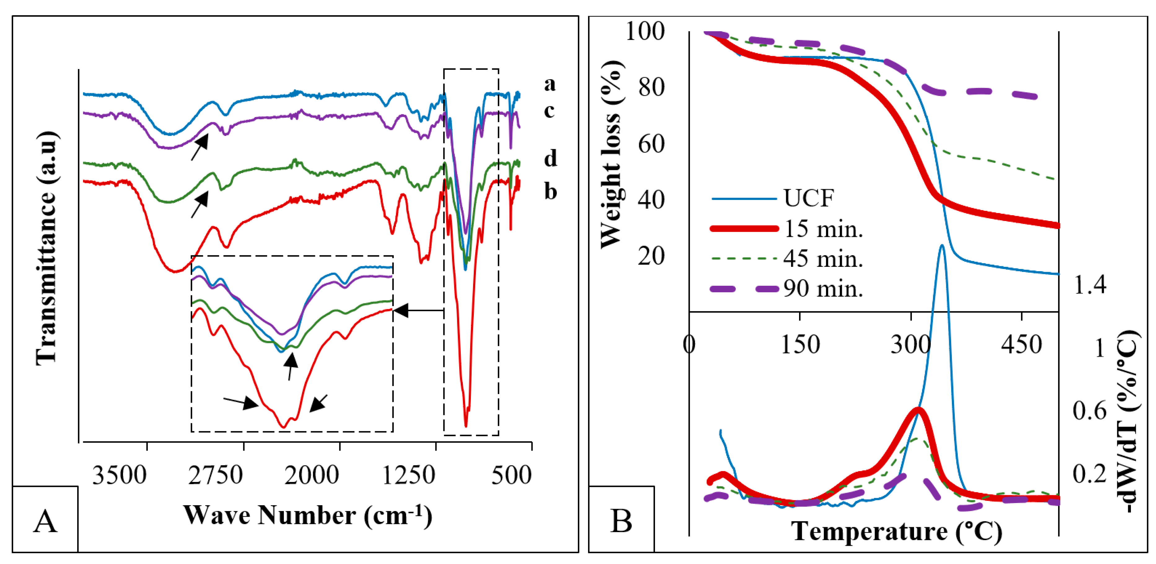
FTIR-ATR spectroscopy, which is a surface-sensitive technique, can illustrate changes in the spectra after chemical treatments. Figure 4A shows the spectra of UCF and copper-coated fibers at 15 min, 45 min, and 90 min immersion time. Compared to UCF (spectrum “a”), the spectra of coated fibers presented changes, particularly peaks between 1200 and 800 cm−1, and bands between 3000 and 2800 cm−1, indicated by arrows. For the 15 and 45 min immersion times, a peak appeared around 1060 cm−1 which can probably be ascribed to the vibration of the Sn–OH bond [14]. This peak disappeared for the 90 min immersion time, which indicates that no more free Sn–Pd molecules were present over the surface of the fiber, and copper is present at all the activated sites. The spectra of the coated fibers showed an extra peak at 2938 cm−1 that corresponded to C–H asymmetric stretching in a new molecular environment.
Figure 4B shows the thermal behavior of the fibers by TGA before and after coating at three different immersion times. The mass loss curves showed three different stages for all fibers. The initial stage extending up to 100 °C is attributed to the evaporation of the adsorbed water on fibers and already shows the difference in their moisture uptake. It can be observed that the sensitivity of fibers to moisture was reduced with the increased concentration of copper.
The second stage largely differed between fibers, corresponding to the degradation of cellulose. The degradation of UCF occurred in a very short range of temperatures between 280 °C and 360 °C [15], leading to more than 70 wt% loss. However, the degradation of all copper-coated fibers started at the same temperature of ~180 °C and spread over an extended range of temperatures, ending at 360 °C (same endpoint as UCF). This is indicated by the difference in the peak size in the derivative of the TG curves. The peak for UCF was higher (indicating greater weight loss) and narrower (indicating the shorter interval over which the weight loss occurs), while all other peaks for the coated fibers were broadened and had a smaller amplitude. The weight loss intensity drop can be attributed to the decrease in the relative amount of cellulose (an increase in the amount of copper), while the shift in the degradation temperature might be attributed to the chemical degradation of cellulose chains during the electroless plating process. The polymeric chains became shorter due to the effect of the chemicals and hence was more susceptible to the subsequent thermal degradation.
The weight loss of the coated fibers showed a difference according to the immersion time, with 51 wt%, 37.5 wt%, and 17 wt% loss for 15, 45, and 90 min, respectively. As the immersion time increased, the degradation temperature was not strongly affected, which may be an indication that the immersion time in the copper-plating bath had no significant effect on the degradation. The final region extending to 500 °C corresponded to the ash contents (residual weight) obtained at the end of the TGA measurement.
4. Conclusions
The possibility of coating commercially-available continuous cellulose fibers with a commercial cyanide-free electroless copper deposition solution to achieve electrically conductive cellulose fibers was investigated. Preliminary results showed the increase in conductivity by increasing the immersion time in the copper-plating bath, trading-off with the loss in mechanical performance due to the sensitivity of these fibers to the chemicals. From the results, it can be concluded that the conditions of the copper-coating process should be optimized to minimize damage. On the other hand, longer times in the copper-plating bath helped to achieve a more uniform coating until 60 min, which might be considered the optimal coating time.
Supplementary Materials
The following are available online at https://0-www-mdpi-com.brum.beds.ac.uk/2079-6439/7/5/38/s1, Figure S1: The top image is the full bundle, coated for 60 min, embedded in epoxy resin. The bottom images are images forming the whole of the bundle for the 90 min spread and embedded in matrix of epoxy. Figure S2: SEM images for the 45 min coating time. The images show that in some parts of the fiber, the coating was discontinuous, but in other parts it was continuous, which makes it difficult to assess the quality of the coating after this plating time. Figure S3: Micrographs of bundles showing the change in color after immersion in a copper-plating bath for 15 min (left) and 90 min (right).
Author Contributions
Conceptualization, A.H. and A.R.; methodology, A.H., A.R., Z.A.-M., R.J.; formal analysis and investigation, Z.A.-M., A.H., A.R., A.O., S.S.C., R.J.; data curation, Z.A.-M; writing—original draft preparation, Z.A.-M. and A.H.; writing—review and editing, Z.A.-M., A.H., A.R., A.O., S.S.C., R.J.; visualization, Z.A.-M., A.H. and R.J.; supervision, R.J.; project administration, A.H. and R.J.; funding acquisition, A.H. and R.J.
Funding
This research was funded by the Swedish Foundation for International Cooperation in Research and Higher Education, STINT, grant number IB2017-7389. The APC was funded by Luleå University of Technology.
Acknowledgments
The authors would like to acknowledge the support from the Smart-WPC project within the framework of Interreg-Nord projects.
Conflicts of Interest
The authors declare no conflict of interest. The funders had no role in the design of the study; in the collection, analyses, or interpretation of data; in the writing of the manuscript, or in the decision to publish the results.
References
- Santamala, H.; Livingston, R.; Sixta, H.; Hummel, M.; Skrifvars, M.; Saarela, O. Advantages of regenerated cellulose fibres as compared to flax fibres in the processability and mechanical performance of thermoset composites. Compos. Part A 2016, 84, 377–385. [Google Scholar] [CrossRef]
- Shen, L.; Patel, M.K. Life cycle assessment of man-made cellulose fibres. Lenzinger Berichte. 2010, 88, 1–59. [Google Scholar]
- Yu, M.C.; Wan, J.X. Environmental Friendly Development of Regenerated Cellulose Fiber Production. DEStech Trans. Eng. Technol. Res. 2017. Available online: http://www.dpi-proceedings.com/index.php/dtetr/article/view/11079 (accessed on 16 April 2019). [CrossRef] [Green Version]
- Das, M. Man-made cellulose fibre reinforcements (MMCFR). In Biocomposites for High-Performance Applications; Ray, D., Ed.; Woodhead Publishing: Cambridge, UK, 2017; pp. 23–55. [Google Scholar] [CrossRef]
- Mahmoudian, S.; Reza Sazegar, M.; Afshari, N.; Uzir Wahit, M. Graphene reinforced regenerated cellulose nanocomposite fibers prepared by lyocell process. Polym. Compos. 2017, 38, 81–88. [Google Scholar] [CrossRef]
- Qi, H.; Liu, J.; Mäder, E. Smart cellulose fibers coated with carbon nanotube networks. Fibers 2014, 2, 295–307. [Google Scholar] [CrossRef]
- Zabetakis, D.; Dinderman, M.; Schoen, P. Metal-Coated Cellulose Fibers for Use in Composites Applicable to Microwave Technology. Adv. Mater. 2005, 17, 734–738. [Google Scholar] [CrossRef]
- Dinderman, M.A.; Dressick, W.J.; Kostelansky, C.N.; Price, R.R.; Qadri, S.B.; Schoen, P.E. Electroless plating of iron onto cellulose fibers. Chem. Mater. 2006, 18, 4361–4368. [Google Scholar] [CrossRef]
- Sittisart, P.; Hyland, M.M.; Hodgson, M.A.; Nguyen, C.; Fernyhough, A. Preparation and characterization of electroless nickel-coated cellulose fibres. Wood Sci. Technol. 2014, 48, 841–853. [Google Scholar] [CrossRef]
- Shchipunov, Y.; Postnova, I. Cellulose Mineralization as a Route for Novel Functional Materials. Adv. Funct. Mater. 2018, 28, 1705042. [Google Scholar] [CrossRef]
- Root, W.; Aguiló-Aguayo, N.; Pham, T.; Bechtold, T. Conductive layers through electroless deposition of copper on woven cellulose lyocell fabrics. Surf. Coatings Technol. 2018, 348, 13–21. [Google Scholar] [CrossRef]
- Hajlane, A.; Kaddami, H.; Joffe, R.; Wallström, L. Design and characterization of cellulose fibers with hierarchical structure for polymer reinforcement. Cellulose 2013, 20, 2765–2778. [Google Scholar] [CrossRef]
- Dolbow, J.; Gosz, M. Effect of out-of-plane properties of a polyimide film on the stress fields in microelectronic structures. Mech. Mater. 1996, 23, 311–321. [Google Scholar] [CrossRef]
- Joy, M.; Nair, B.N.; Mohamed, A.A.P.; Warrier, K.G.; Hareesh, U.N.S. One-Pot Hydrothermal Synthesis of Visible-Light-Responsive MoS2/g-CNO Heterostructures for Organic-Pollutant Degradation. Eur. J. Inorg. Chem. 2016, 24, 3912–3920. [Google Scholar] [CrossRef]
- Carrillo, F.; Colom, X.; Sunol, J.J.; Saurina, J. Structural FTIR analysis and thermal characterisation of lyocell and viscose-type fibres. Eur. Polym. J. 2004, 40, 2229–2234. [Google Scholar] [CrossRef]
Figure 1.
Optical micrographs (OM) of the cross-sections (top) and JEOL JCM-6000 Neoscope scanning electron microscope (SEM) images of the fiber surface (bottom) of (a) coated fibers after 15 min, (b,d) 60 min, and (c,e) 90 min immersion time in a Cu-plating bath.
Figure 1.
Optical micrographs (OM) of the cross-sections (top) and JEOL JCM-6000 Neoscope scanning electron microscope (SEM) images of the fiber surface (bottom) of (a) coated fibers after 15 min, (b,d) 60 min, and (c,e) 90 min immersion time in a Cu-plating bath.

Figure 2.
Electrical resistance of 50 mm long samples.

Figure 3.
Mechanical properties: (circles: modulus, rhombus: strength).

Figure 4.
(A) Fourier-transform infrared (FTIR) analysis: a, b, c, d spectra correspond to uncoated and coated fibers for 15 min, 45 min, and 90 min respectively; (B) Thermo-gravimetric analysis (TGA) analysis (top) and derivative of thermo-gravimetric curves (bottom).
Figure 4.
(A) Fourier-transform infrared (FTIR) analysis: a, b, c, d spectra correspond to uncoated and coated fibers for 15 min, 45 min, and 90 min respectively; (B) Thermo-gravimetric analysis (TGA) analysis (top) and derivative of thermo-gravimetric curves (bottom).

© 2019 by the authors. Licensee MDPI, Basel, Switzerland. This article is an open access article distributed under the terms and conditions of the Creative Commons Attribution (CC BY) license (http://creativecommons.org/licenses/by/4.0/).
Share and Cite
MDPI and ACS Style
Al-Maqdasi, Z.; Hajlane, A.; Renbi, A.; Ouarga, A.; Chouhan, S.S.; Joffe, R. Conductive Regenerated Cellulose Fibers by Electroless Plating. Fibers 2019, 7, 38. https://0-doi-org.brum.beds.ac.uk/10.3390/fib7050038
AMA Style
Al-Maqdasi Z, Hajlane A, Renbi A, Ouarga A, Chouhan SS, Joffe R. Conductive Regenerated Cellulose Fibers by Electroless Plating. Fibers. 2019; 7(5):38. https://0-doi-org.brum.beds.ac.uk/10.3390/fib7050038
Chicago/Turabian StyleAl-Maqdasi, Zainab, Abdelghani Hajlane, Abdelghani Renbi, Ayoub Ouarga, Shailesh Singh Chouhan, and Roberts Joffe. 2019. "Conductive Regenerated Cellulose Fibers by Electroless Plating" Fibers 7, no. 5: 38. https://0-doi-org.brum.beds.ac.uk/10.3390/fib7050038
Note that from the first issue of 2016, this journal uses article numbers instead of page numbers. See further details here.