Effects of Hybridisation on the Low Velocity Falling Weight Impact and Flexural Properties of Flax-Carbon/Epoxy Hybrid Composites

School of Mechanical and Design Engineering, University of Portsmouth, Portsmouth PO1 3DJ, UK
*
Author to whom correspondence should be addressed.
Fibers 2019, 7(11), 95; https://0-doi-org.brum.beds.ac.uk/10.3390/fib7110095
Submission received: 26 June 2019
/
Revised: 3 October 2019
/
Accepted: 14 October 2019
/
Published: 24 October 2019
(This article belongs to the Special Issue Natural Fiber-Reinforced Hybrid Composites)
Abstract
:The trend of research and adoption of natural plant-based fibre reinforced composites is increasing, with traditional synthetic fibres such as carbon and glass experiencing restrictions placed on their manufacture and use by legislative bodies due to their environmental impact through the entire product life cycle. Finding suitable alternatives to lightweight and high-performance synthetic composites will be of benefit to the automotive, marine and aerospace industries. This paper investigates the low-velocity impact (LVI) and flexural properties and damage characteristics of flax-carbon/epoxy hybrid composites to be used in structural lightweight applications. LVI, for example, is analogous to several real-life situations, such as damage during manufacture, feasibly due to human error such as the dropping of tools and mishandling of the finished product, debris strikes of aircraft flight, or even the collision of a vessel with another. Carbon fibre has been hybridised with flax fibres to achieve enhanced impact and flexural performance. The failure mechanisms of woven flax and flax-carbon epoxy hybrid composites have been further analysed using Scanning Electron Microscopy (SEM). It was observed from the experimental results that carbon fibre hybridisation has a significant effect on the impact and flexural properties and their damage modes. The results obtained from this study exhibited that the flexural strength and modulus of plain flax/epoxy composite increase significantly from 95.66 MPa to 425.87 MPa and 4.78 GPa to 17.90 GPa, respectively, with carbon fibre hybridisation. This significant improvement in flexural properties would provide designers with important information to make informed decisions during material selection for lightweight structural applications.
1. Introduction
The rise in global warming and the increased public awareness of the impact of pollution arising from the use of non-renewable sources is driving governments and business sectors to tackle climate change. There are many initiatives undertaken to stabilise and reduce the impact of greenhouse gasses (GHGs) on the natural world. The European Union (EU) for example has set penalties in the form of registration premiums [1] for all new vehicles registered, which exceed emission targets.
Natural fibres have a lower density and problem-free disposal, leading to them being a strong emerging alternative to synthetic fibres [2].
Composites Evolution [3] have produced a car door using a carbon/flax hybrid system. The company suggests that the mechanical properties of the carbon fibre are not significantly lost in a system where the inner layers of the composite structure are replaced with flax fibre. On the contrary, the flax fibre is proposed to reduce noise, vibration, and harshness throughout the structure. A study performed by the Composites Evolution (“Reducing the Cost, Weight and NVH of Carbon Fibre,” 2014) has found that a carbon/flax hybrid system is 15% cheaper, 7% lighter, and displays 58% greater vibration damping qualities over a full carbon fibre composite. Also, the flexural modulus is almost identical to carbon fibre, the latter scoring 47 GPa and a carbon/flax hybrid composite achieving 44 GPa. The company uses a 50/50 ratio of carbon/flax fibre, with the outermost layers consisting of carbon fibre.
A very interesting point has been made [4] that natural fibre composites offer an almost Carbon Dioxide (CO2) neutral disposal process based on the captured CO2 in natural fibres during their growth.
A growing awareness of industrial environmental impact has stimulated research into the development of environmentally friendly and sustainable materials [5]. Dhakal et al. investigated the effects of fibre orientation and thickness of natural fibres under an impact load. This study characterises the damage mechanisms in natural fibres throughout an impact event. It finds that after the samples are loaded beyond their elastic limit, damage begins to occur, in the form of matrix cracking. As the load continues the increase, the further onset of damage is seen as interfacial debonding as the specimen reach their peak loading. After this point, delamination and fibre breakage takes place until ultimately the sample is penetrated by the hemispherical tup. The orientation of fibres, fibre volume fraction, and matrix properties all have a significant effect on the damage type and severity observed.
Research into flax fibre reinforced epoxy composites [6] suggests that while flax may be considered one of the strongest natural fibre replacements for synthetic fibres, data on the transverse, shear, and compressive response of flax reinforced components is limited. The study found that delamination and fibre breakage is most prevalent in shear failure; while defibrillation and fibre cracking is presents under tensile loading. They suggest that matrix-related damage events, such as cracking and plasticity, are not a significant contributor to damage initiation or failure in flax composites.
The work undertaken by Sarasini et al. [7] studied the effects of layer sequencing on carbon/flax hybrid composites. An impact test in their work was carried out on four different configurations at energies between 5 and 30 J, in 5 J increments. While flax showed a better energy absorption capacity, it suffered greater internal damage and high compliance. The study found that the arrangement of carbon fibre on the outer layers, with inner flax fibre ply, has the best flexural performance. The damage pattern in the carbon samples showed a propagation of shear cracks moving far away from the impact zone, whereas the flax samples suffered heavy delamination. The samples with outer flax layers saw better mechanical and impact absorption properties over using a flax core. The flax samples began to show signs of penetration after 30 J, in 18-layer samples.
A study into natural fibre hybridisation by Dhakal et al. [8] looked into the performance of a hybrid natural fibre composite material, of hemp/basalt. The study found that natural fibres alone suffer critical issues with low post-impact residual damage tolerance through early fibre fracture and matrix cracking; however, the basalt skins assisted in delaying fractures of the hemp core, suggesting there are grounds for further investigating natural fibre hybridisation.
The effects of hybridising natural fibres with other materials [9], in this case, basalt, have brought an improvement of mechanical properties, such as improved resistance to impact damage and residual flexural strength properties compared to non-hybrid composites.
In recent years, critical engineering sectors, such as automotive, marine and aerospace are looking for lightweight composite materials to reduce their overall cost and weight with improved functionality [10]. The main goal of this study is to investigate the influence of carbon fibre hybridisation on the mechanical properties of carbon fibre epoxy, flax fibre epoxy, and a hybrid carbon/flax epoxy composite structure. This will be of direct benefit to industries aiming to reduce their carbon footprint by investigating a combination of natural and synthetic materials, which offer greater mechanical properties in certain applications.
Furthermore, using a variety of damage characterisation methods, this study will attempt to understand and highlight the failure mechanisms of hybrid systems, which will be useful for design engineers using composite materials to design components.
2. Materials and Methods
2.1. Materials
The two reinforcing materials used were epoxy-based prepregs ‘HexPly M56’ unidirectional carbon fibre and ‘SDH VTC401LV’ unidirectional flax fibre. Epoxy-based carbon and flax reinforcements used were obtained from Gurit and SHD Composites, respectively. The ‘HexPly M56’ [11] unidirectional carbon tape epoxy based prepreg, with a fabric weight of 280 g/m2 supplied by Gurit, has a fibre density of 1.78 g/cm3.
The flax fibre prepreg unidirectional mats with a fabric weight of 350 g/m2 were obtained from SHD Composites, based on a VTC401 epoxy component. The flax fibres have a density of 1.5 g/cm3, and in this case, the fibre volume of the prepreg is 50%.
2.2. Sample Preparation
The samples have the same layup procedure before being cured in the oven to their respective manufacturer specifications. The unidirectional prepreg is laid up into generic sheets of eight layers with a stacking sequence specified in Table 1. This ensures that the interface between carbon and flax in the hybrid composite is opposed at 90 °C and that there is a symmetrical distribution of fibre plies. The averages of fibre volume fraction (FVF) for flax/epoxy, carbon/epoxy, and flax-carbon/epoxy hybrid composites were approximately 56%, 59%, and 58%, respectively.
The material uses a vacuum bag to de-bulk and removes as much air as possible; a test is carried out by sealing the bag and removing the applied vacuum to ensure there are no vacuum leaks.
The samples were cured under similar conditions. The only difference was their ramping and dwelling temperatures, which were from 20 °C to 180 °C ± 5 °C and 180 °C ± 5 °C, respectively for CFRP composite sample, and 20 °C to 135 °C ± 5 °C and 135 °C ± 5 °C for FFRP and its hybrid samples. These temperatures were effective to obtain expected full curing. To ensure full cure of the matrix, a differential scanning calorimetry (DSC) test was performed and the correct glass transition temperature was measured.
Once the layup is complete, and the samples have been correctly de-bulked, the panels were placed in the oven for a controlled curing cycle as specified by the manufacturer of the prepreg epoxy resin. Temperature ramps are strictly controlled to ensure that the resin correctly cures; otherwise high-temperature snap curing can have reduced effectiveness as the impregnated resin is not allowed to flow to specification. After successful curing, the samples were CNC waterjet cut to sprue style templates for final collection and damage characterisation testing.
2.3. Low-Velocity Falling Weight Impact Testing
An impact test was undertaken on ZwickRoell HIT230F (ZwickRoell GmbH, Ulm, Germany), using preformed impact test samples. The incident impact energy was set at 25 joules (enough to penetrate the flax samples); with an impact velocity of 1.468 m/s and a total mass of 23.11 kg from a height of 110 mm. The specimens were firmly fixed at all edges using annular clamps with inner and outer diameters of 50 and 75 mm respectively. The specimens were cut by waterjet cutting from the laminate to a specimen size of 70 mm × 70 mm. Four specimens were impacted per each composite category and average values were taken.
The data obtained from the test was used to understand and evaluate the behaviour of carbon fibre alone, flax fibre alone, and carbon/flax hybrid composites under impact loading. It is important to understand how the material is deforming, and the failure modes that are present.
The impact samples were fully supported on a hardened steel retaining surface. Each specimen’s thickness was measured in 90° incremental rotations using calibrated digital calipers. An average thickness, 2 mm for each sample, was obtained for each sample and then further averaged to give a total specimen thickness.
2.4. Flexural Testing
The flax/epoxy, carbon/epoxy and flax-carbon/epoxy hybrid composites were tested for determining flexural strength and modulus using a three-point bending test on a ZwickRoell Z030 (ZwickRoell GmbH, Ulm, Germany) machine in accordance with the BS EN 2746:1998 test method. A total of five samples were tested for each type of composite with a crosshead speed of 2 mm/min. The span-to-thickness ratio was kept at more than 16 times the thickness of the specimens. The panel thickness was approximately 2 mm for each specimen. Four specimens from each composite laminate were tested, and average values were taken.
The width and thickness of each sample were measured in three locations evenly distributed across the specimen’s length. An average of the measurement data was obtained to be used to calculate the cross-sectional area, which was ultimately used to calculate the flexural strength and modulus of the specimen.
2.5. Damage Modes Characterisation
2.5.1. SEM
The fractured surfaces of failed samples under impact and flexural loadings were cut to fit within the vacuum chamber of the Zeiss Evo 10 scanning electron microscope (SEM) (Carl Zeiss Microscopy GmbH, Jena, Germany). The parted samples were then individually bagged to reduce contamination and then bonded to aluminium mounting stubs, and the specimen is coated in gold/palladium (Au/Pd) before entering the vacuum chamber.
2.5.2. Visual Inspection
The samples were catalogued with a digital camera; failure modes were observed and recorded.
3. Results and discussion
3.1. Impact Damage Characteristics
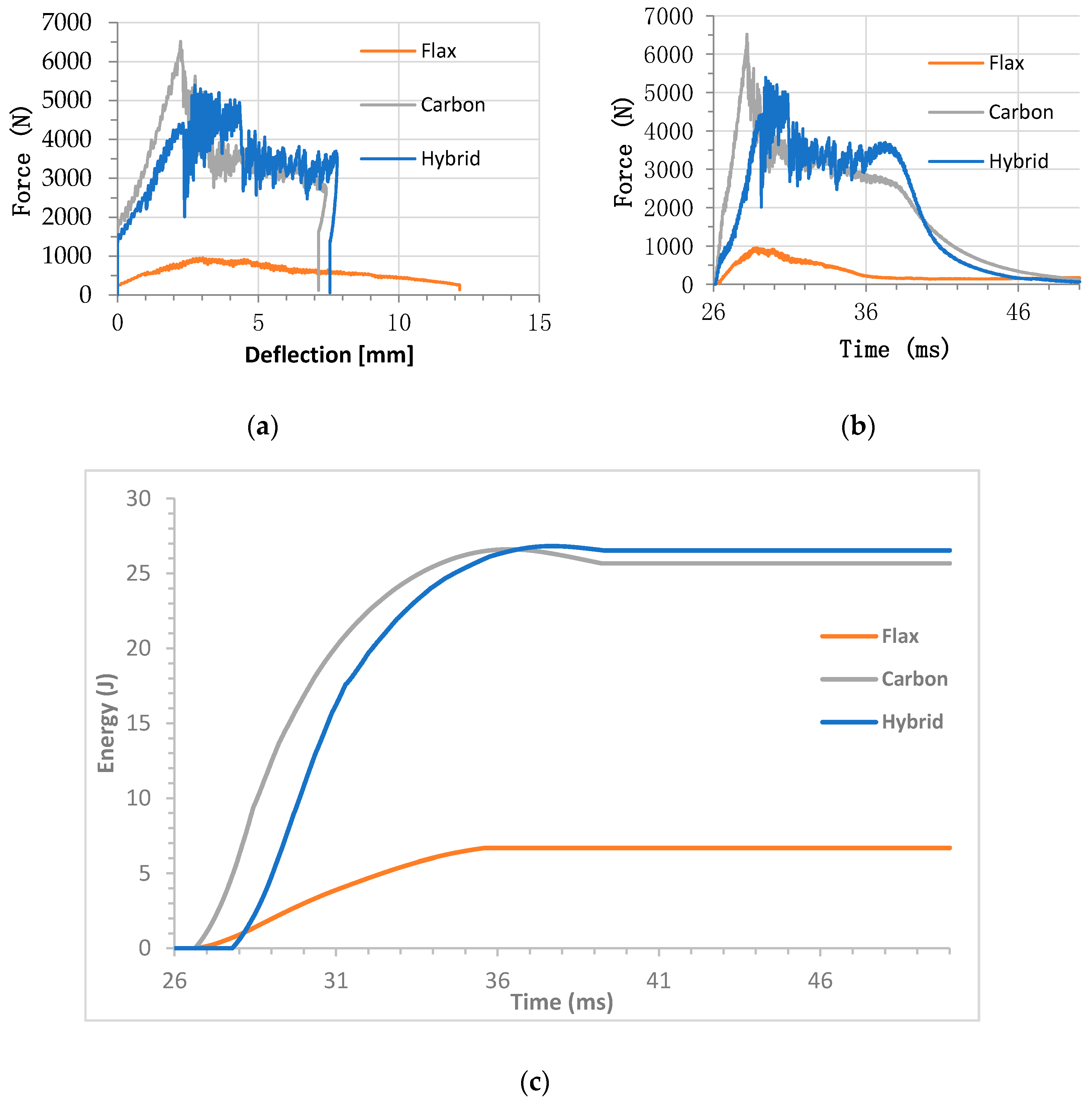
Three different types of composite materials were investigated in this study, namely: flax/epoxy, carbon/epoxy, and flax-carbon/epoxy hybrid composites. The impact test results, shown in Figure 1, are a comparison of these three composite types, calculated by taking the average for each material and finding the sample with the smallest deviation from the average.
In Figure 1a, it is noticeable that the plain flax/epoxy sample shows lower impact force during the impact event, with no return load (rebound) showing that the material has been completely penetrated with a lowest peak force of approximately 0.93 kN, and a highest deflection of approximately 12 mm. The rise in the displacement curve is consistent with the travel of the hemispherical tup impacting the flax specimen and then each layer taking up the slack, finally reaching the fracture point where the tup begins to traverse the topmost layer down consistently through each subsequent layer until it pierces the bottom-most layer.
The carbon/epoxy curve shows the highest impact force, approximately 6.51 kN, with the lowest deflection, approximately 7 mm. The rebound in the force-displacement curve is an indication that the impact probe has not sufficiently penetrated the sample.
The flax/epoxy sample had a greater deflection than the carbon/epoxy and flax-carbon/epoxy hybrid sample, but significantly lower impact force. However, the flax-carbon/epoxy hybrid specimen exhibited slightly higher deflection than the carbon/epoxy specimen with slightly lower impact force, approximately 5.39 kN. A point worthy of highlighting here is the deflection at peak force. The deflection recorded for the hybrid specimen is 2.74 mm, which is higher than that of the carbon/epoxy specimen. Similar observations can be made in peak energy. The flax/epoxy samples have shown the lowest energy absorption, approximately 7 joules, whereas the flax-carbon/epoxy hybrid sample had an almost identical energy (27 joules) to that of the carbon/epoxy samples shown in Figure 1c. This is due to higher damping properties of the flax core ply inside the hybrid composite. As the impact event is occurring and each layer takes up slack, the flax layers are able to absorb a greater amount of energy than that of the carbon fibre outer layers when they are put in tension. Because of this, the flax fibre inner layers will fail before the carbon fibre outer layers; experiencing debonding, delamination, and fibre pull-out before the failing of the carbon layers. This is shown in the trace for Figure 1a; as the load is applied and slack is taken up it moves at a constant rate, however after a deflection of 2 mm the carbon/flax specimen experiences an initial drop in force where the impact weight enters freefall. This is because the inner flax fibres delaminate from the carbon outer layer. Once the carbon layer takes up the slack again it cannot handle the shock load and begins to fail; after this point, the topmost carbon layers debond longitudinally to the unidirectional layup, with the carbon fibres finally breaking after 4 mm of drop weight travel through the sample. These observations can be related to the front and rear faces of the impacted samples.
The hybrid carbon-flax/epoxy does not reach peak load before serious fibre breakage, or delamination begins to occur in the data of Figure 1a. The force transferred into the impact sample drops momentarily by 2 kN. At the same time the work exerted on the sample has a small plateau at 28 ms into the rest as shown in Figure 1c. The force then climbs until reaching the peak load and oscillates as the impact tip tears through the fibres and matrix layers.
What is very interesting is how the carbon/flax hybrid sample shows harmonic resonance after the initial flax inner fibre failure [12], where the force applied also rings as it is dampened. Here, the flax layers, which have not yet failed, are damping the resonance which the carbon layers are experiencing.
The carbon/flax hybrid shows a similar pattern to carbon fibre with similar deformation potential; however, the downslope shows greater step sizes due to the different failure modes of the hybrid composite. The interfaces between the immediate carbon and flax layers proved to be weak and showed a very large delamination affected zone.
Another recent study supports the carbon/flax impact results [7], which shows a hybrid carbon/flax sample with a flax-fibre core exhibiting a peak force 82% below that of carbon; this report shows the hybrid carbon/flax sample demonstrating a peak force of 84.5% of carbon alone.
As the hemispherical impact tup traverses through the impact sample, plain carbon fibre epoxy and flax-fibre epoxy both exhibit predictable behaviour; however, the hybrid samples show interesting behaviour.
The carbon sample has a consistent application of force until it has reached its peak load at 2.237 mm. Between 2 mm and 4 mm of displacement, the impact object traverses the multiple layers of the sample, with a sharp reduction in force of 1500 N every 0.5 mm as it breaks a new layer until it comes to rest after breaking every fibre layer.
In Figure 1c, flax-fibre shows a smaller total amount of energy transferred between the probe and the sample, with the rate of transfer having a slower curve than that of the other samples. The probe comes to rest after penetrating the sample approximately 10 ms into the test, with force ceasing to be applied once maximum deformation has been reached. This is due to the difference in the stresses between the flax fibres and the matrix interface being large enough for debonding and delamination to begin to occur earlier than in the plain carbon or carbon/flax samples [2].
The carbon/epoxy and flax-carbon/epoxy hybrid systems show a consistent downslope in Figure 1b after 36 ms, due to energy being transferred back into the impact probe, as the fibres (still within their elastic limit) return to their original elongation. The carbon/epoxy specimen shows a more consistent reduction in the force applied until recoil; however, flax exhibits an arc of force applied to increase before recoil, demonstrating the dampening properties of the flax layers within the sample. Similar positive hybrid effects on the impact behaviour of natural fibre composites were reported by Sarasini et al. [13]. with intraply hybrid flax-basalt composites. The natural fibre reinforced composites have low impact resistance behaviour compared to their conventional counterparts, such as glass and carbon fibre reinforced composites. A significant impact properties enhancement with the carbon fibre hybridisation is a very positive achievement towards using these sustainable composites as an alternative to pure synthetic composites in load-bearing applications while maintaining their partial green attributes.
3.2. Flexural Properties
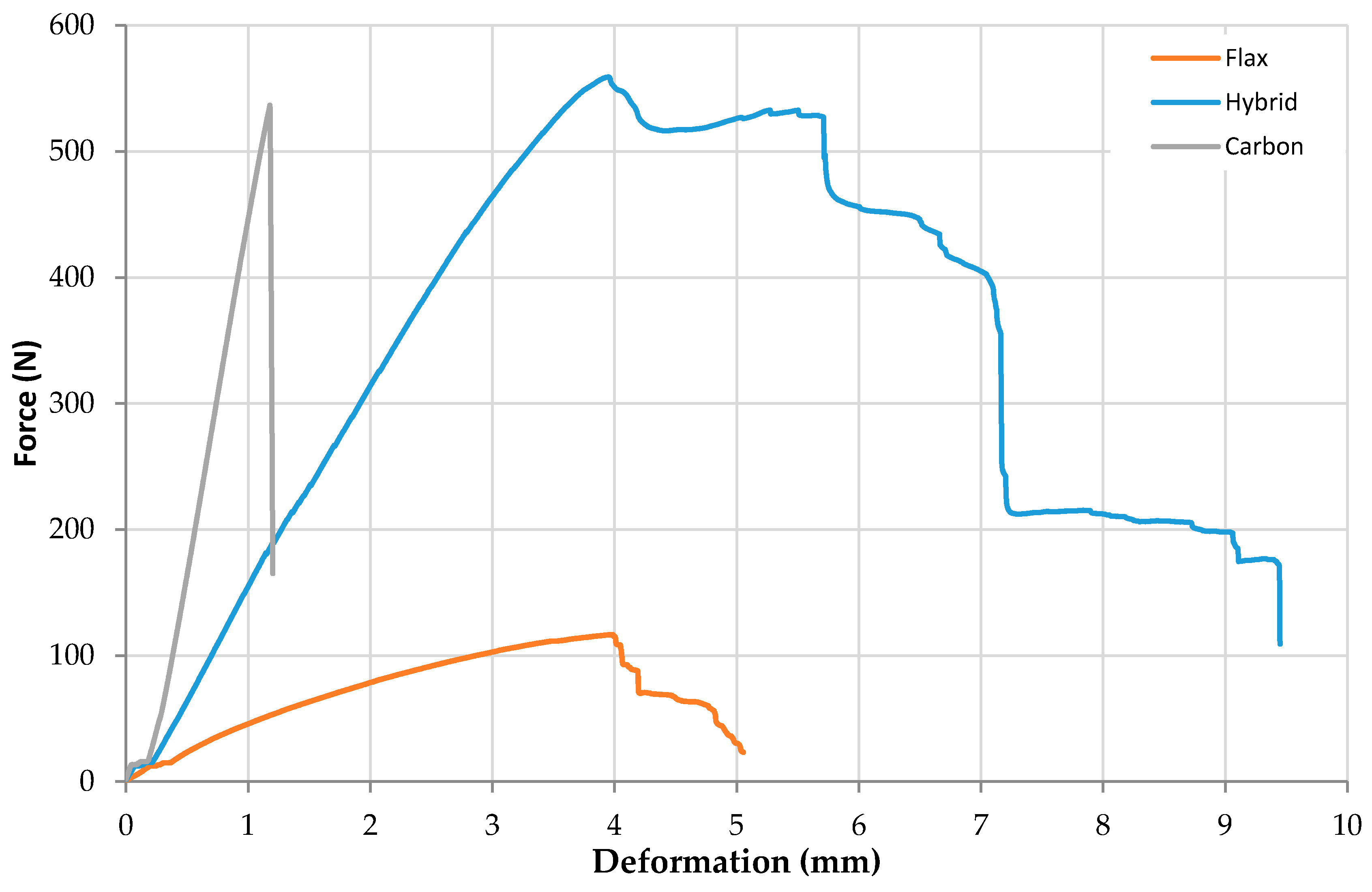
The average flexural properties of three different types of composites are presented in Table 2, and load vs. deformation traces of these composites are shown in Figure 2. It can be extrapolated from the results illustrated in Figure 2 that flax-carbon/epoxy hybridised samples have shown a significant improvement in flexural strength and modulus. Precisely, the flexural strength of plain flax/epoxy increases significantly from 95.66 MPa to 425.87 MPa (an approximate 345% improvement) with carbon fibre hybridisation. Similarly, the flexural modulus of plain flax composite was increased from 4.78 GPa to 17.90 GPa (an approximate 274% improvement) with carbon fibre hybridisation. These values represent the highest mean value amongst the studied composites. The significant enhancement in flexural modulus is dependent on several factors such as fibre content and modulus of fibre itself. Moreover, the compatibility between flax and carbon fibre as well as matrix and reinforcements may have contributed to the improvement in flexural modulus. This improvement is further attributed to the effect of hybrid mechanisms. The lay-up sequence for hybrid composites was two layers of high-modulus carbon fibres on the outside surfaces, and the pure flax fibre in the middle has contributed the highest strength and modulus. It is worth noting that flax fibre is a very stiff material which has further contributed to this significant flexural properties’ improvement. The attainment of such property enhancement with carbon fibre hybridisation provides a significant potential of natural fibre hybrid composites to be used for structural light weight applications [14].
The incredibly high-flexural properties of the carbon/flax hybrid could support a theory of a very strong interfacial relationship between carbon fibre and flax fibre in an epoxy laminate under flexural load. Similarly, the flexural deformation was significantly higher, increasing from 1.16 mm to 3.96 mm (an approximate 241% improvement) for flax-carbon hybrid systems compared to carbon/epoxy systems, indicating a hybrid system is a valid approach towards achieving an improved mechanical performance of natural fibre reinforced composites.
3.3. Damage Characterisation
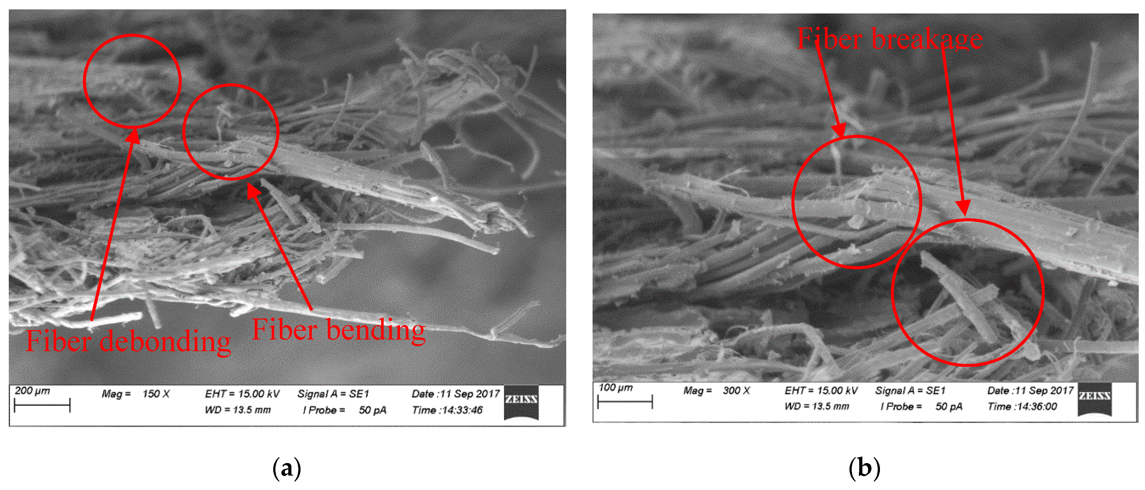
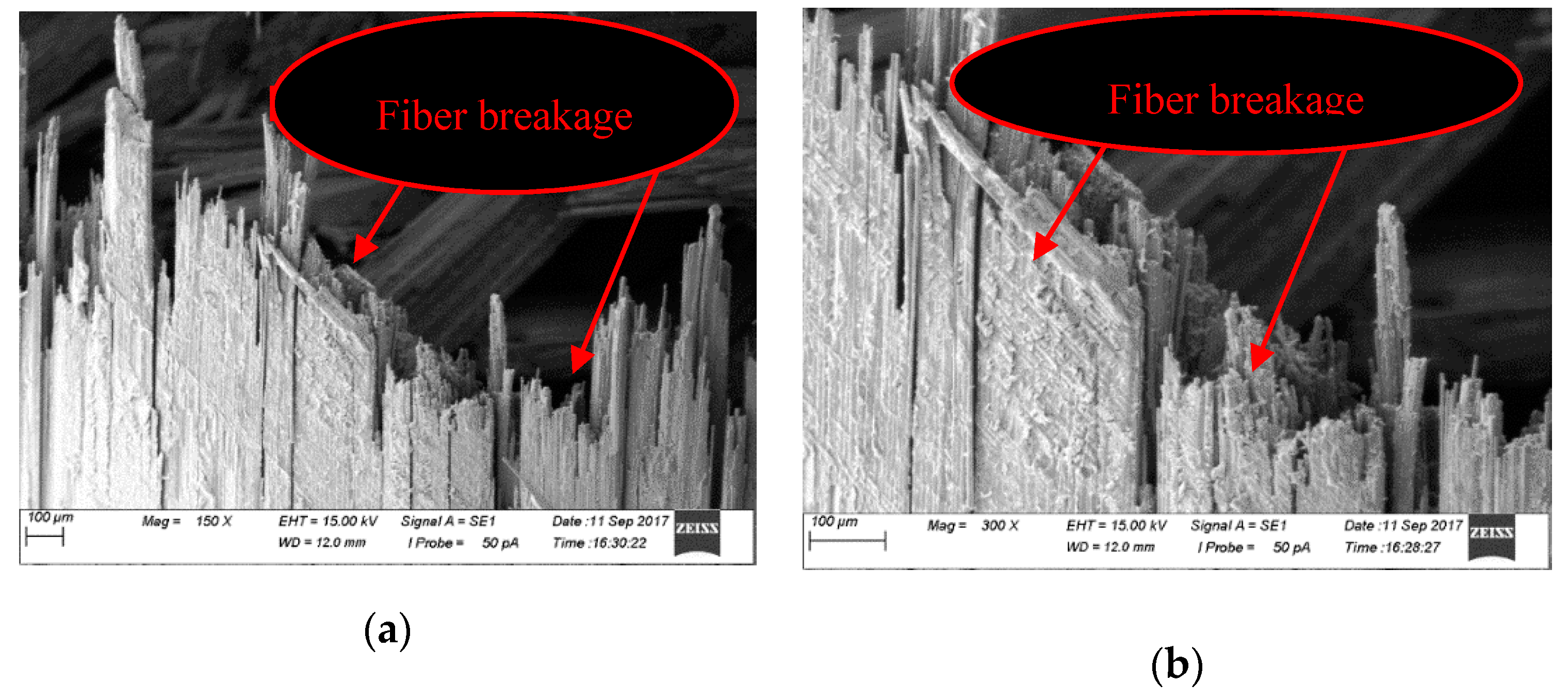
3.3.1. SEM Images of Plain Flax/Epoxy Composites under Impact
Scanning electron microscopy (SEM) images of fractured surfaces after the impact of plain flax/epoxy composites are presented in Figure 3a,b which shows extensive fibre breakage and disorder, with one large group of fibres becoming an initial focal point. The following magnification scales (150 and 300), display matrix cracking and debonding of the epoxy from individual fibres, and additionally show the fibre bending and debonding around a kink band of the flax fibres structure, with clear twisted and flattened fibres. Similar failure mode under the low velocity impact testing was reported by Dhakal et al. for hemp fibre reinforced unsaturated based composites [15].
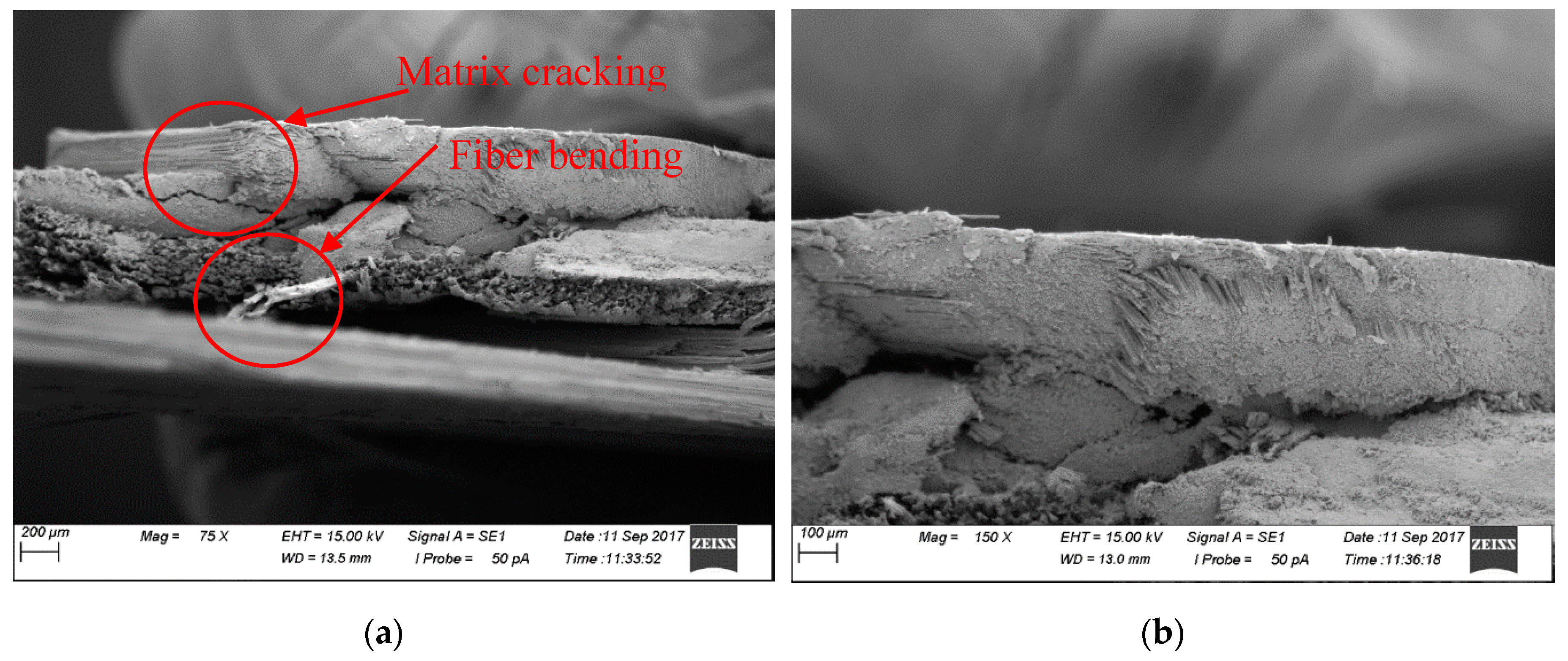
3.3.2. SEM Images of Plain Flax/Epoxy Composite under Flexural Loading
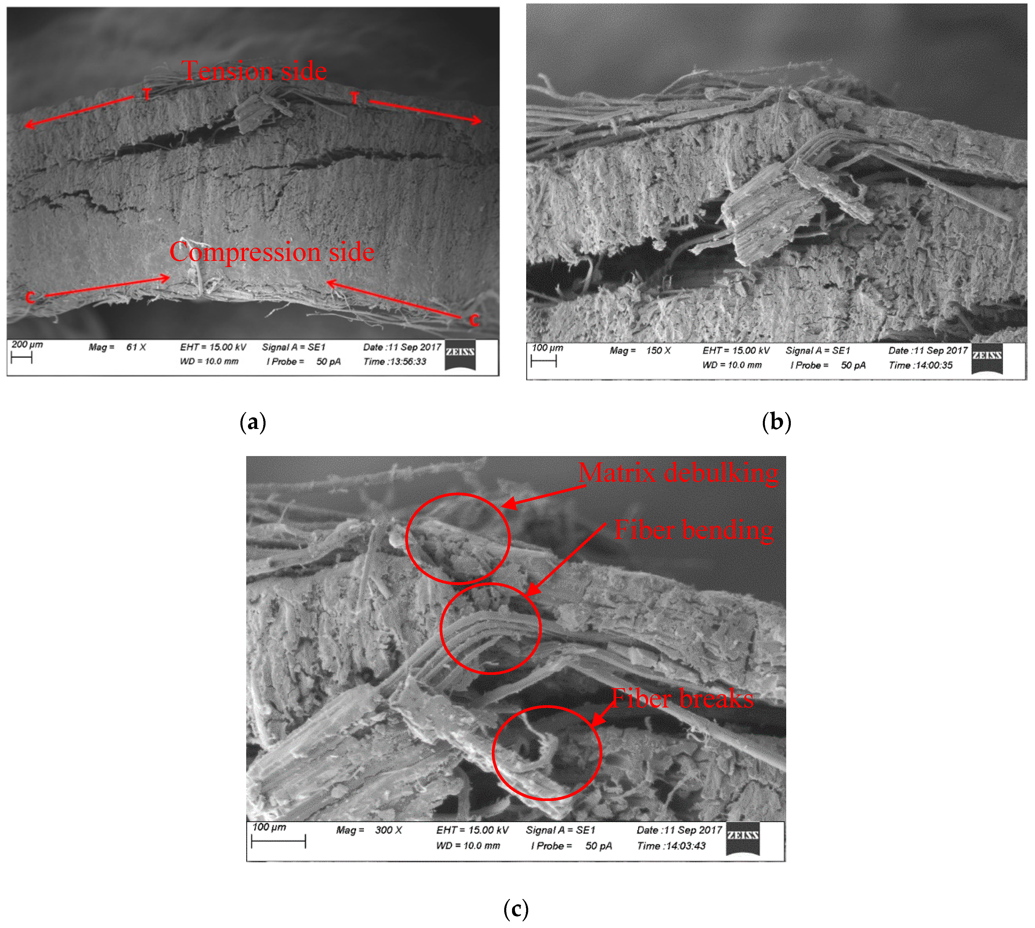
SEM images of the fractured surfaces of plain flax/epoxy composites following flexural loading are shown in Figure 4. In Figure 4a, the tensile (T) and compressive (C) load paths have been annotated. It is clear that under three-point bending, natural fibres are heavily affected by not only the tensile stresses but also compression which causes a large amount of compaction on the bottom of the image, where the loading nose would exert force. This could cause excessive debonding and shear slippage.
Figure 4b shows the result of the fractured surface after the flexural test, as the outer layer has been debonded from the inner layers at a 0/+45° intersection of the flax fibre epoxy, with a large portion of the epoxy matrix released, shown in Figure 4c, from the crack with several fibres still attached. More enhanced views in Figure 4c show the origin of the released matrix bundle, with highly fragmented matrix portions at this site.
3.3.3. SEM Images of Plain Carbon/Epoxy Composites under Impact Loading
Figure 5 shows uniform breakage as an outer layer of flax fractures upon receiving a flexural load transverse to the plane of the unidirectional fibre layer. This perspective would be facing the impact tup as it travels through the SEM image.
Figure 5a shows that along with uniform fracture points on each fibre, the severe delamination pattern from the released outermost layer of carbon still presents in the epoxy matrix. This pattern is more visible in Figure 5b; the fibres are failing with small delamination visibly occurring and cracks running longitudinally along fibres.
Moving the focal length down into the impact sample in Figure 5, the multiple layers are visible with excessive breakage apparent as fibres have been pushed between layers by the impact event.
3.3.4. SEM Images of Plain Carbon/Epoxy Composites under Flexural Loading
The image above, Figure 6a,b, shows multiple carbon fibre layers after having performed a three-point flexural test. Figure 6 shows a very uniform pattern of fibres, even after breakage. This is highly contrasting to the flax fibre failures, where individual fibres are chaotic, such as flax in Figure 4. Figure 6 shows fibre breakage, and a cluster of fractures fibres 100 µm long are distorted away from the layer’s plane, however the fibres continue to orient themselves through a cohesive matrix; this is a good example of the brittle nature of carbon fibre epoxy. It can be seen that the matrix is seen to be partially fragmented, but as the failure was not an explosive release of high tension the matrix did not shatter and spread itself as an airborne particulate across the surrounding material.
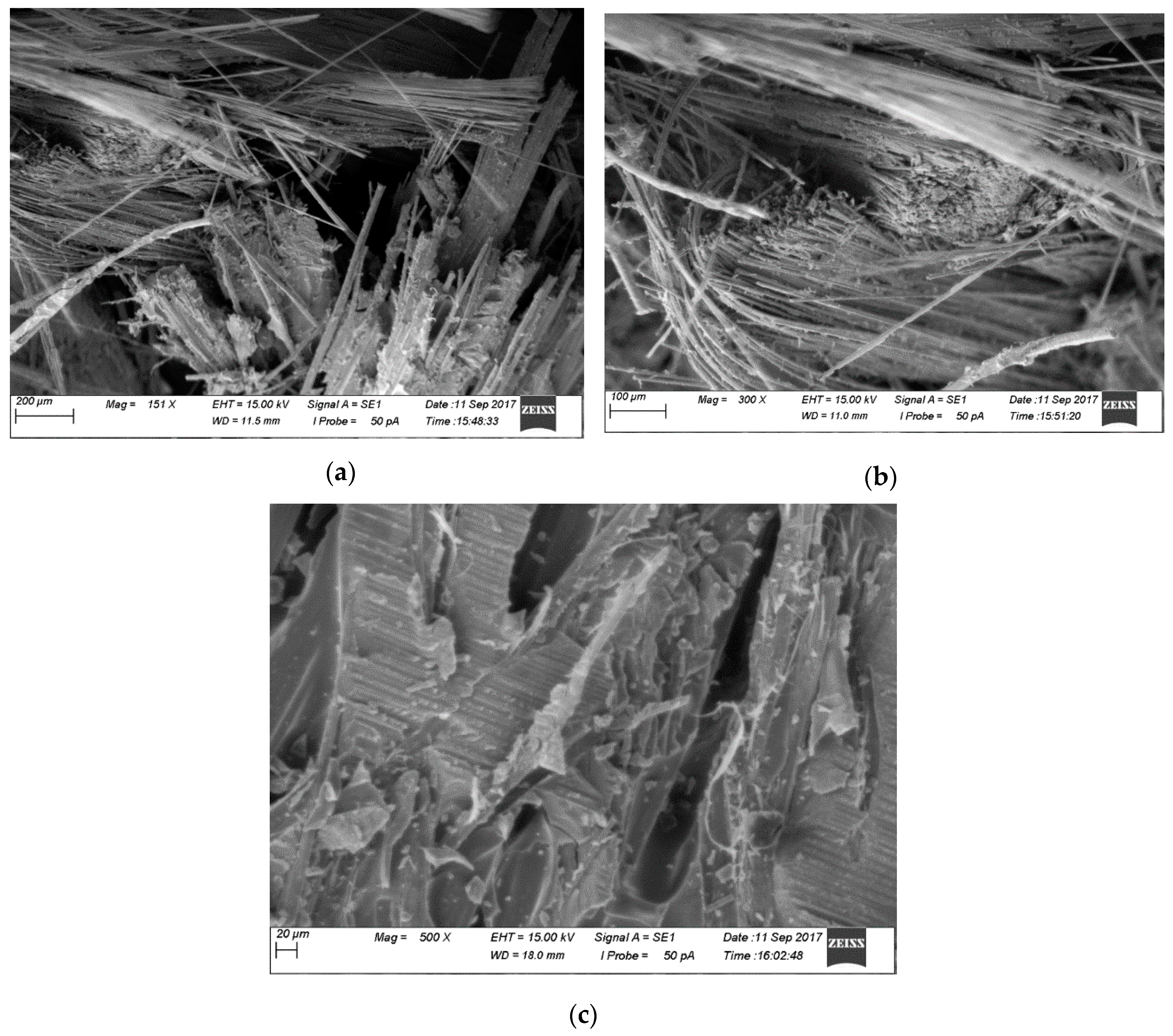
3.3.5. SEM Images of Flax/Carbon/Epoxy Hybrid Composites under Impact
Figure 7a,b display the internal flax fibre core from the hybrid composite impact test, which exhibits a wide area of damage through the fibres, with a high degree of fibrillation present on the large fibres. When enhancing Figure 7c, the portion of the matrix shows significant cracking, tearing and delamination; with the fibres still attached becoming highly twisted and distorted as the matrix has been ejected from the primary sample body.
A further view of Figure 7a,b display both carbon and flax fibres in a chaotic site, where flax fibres from the core piles have intersected the carbon layer. The carbon to flax interface is at a 90° orientation, at a +45° offset to the topmost layer of the sample. At a higher magnification, the expected result is seen from an explosive event in a carbon fibre matrix structure. The carbon fibres that have debonded from the epoxy matrix have scattered and have not remained as a group; such as with carbon three-point bending.
Furthermore, the third site of interest is a fantastic example of fibre pull-out and the matrix surface after complete delamination. Again, in Figure 7, it can be seen that the flax fibre epoxy matrix has delaminated from the carbon fibre interface, leaving a strong pattern of convex valleys at a 90° orientation to the flax fibre direction. After increasing the magnification, Figure 7c shows the same explosive carbon fibre matrix contamination left behind on the matrix surface of the flax fibre layer.
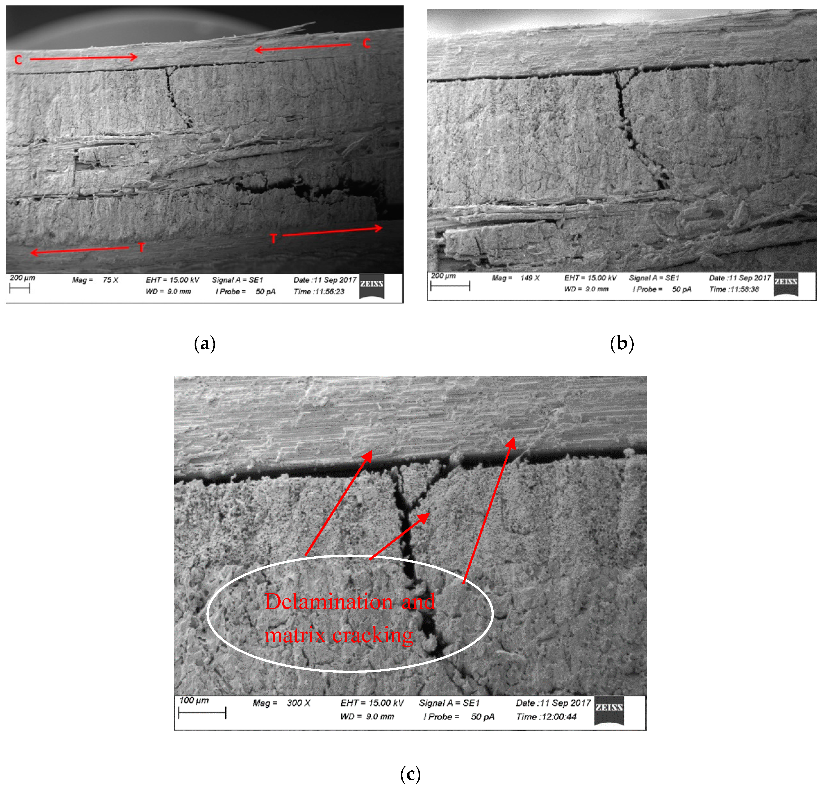
3.3.6. SEM Images of Flax-Carbon/Epoxy Hybrid Composites under Flexural Loading
3.4. Visual Inspection of Damage Modes
3.4.1. Visual Observation of Impact Damage
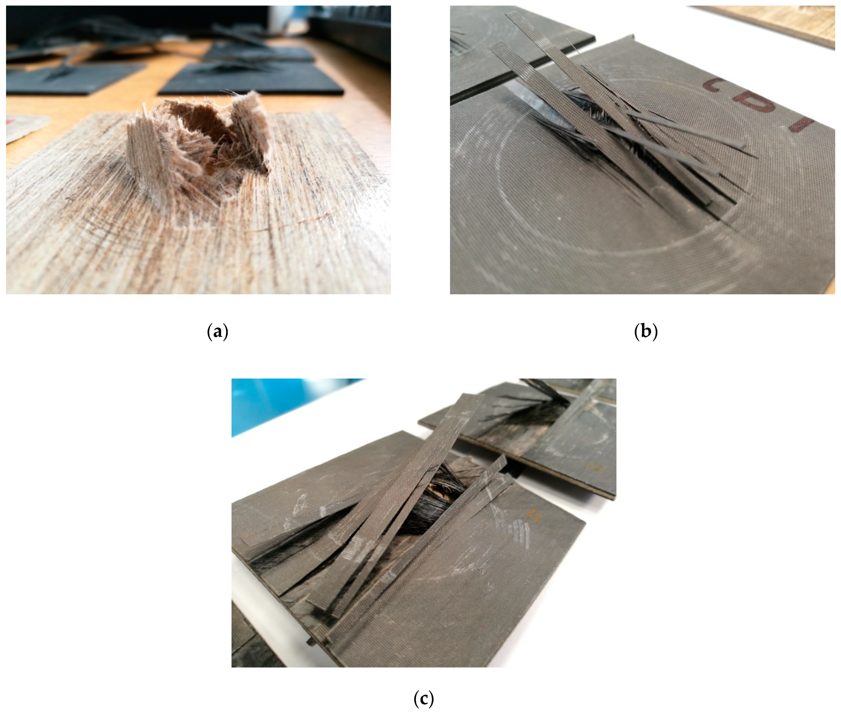
Figure 9 displays the failed surfaces of impact loading showing rear sides of the samples, namely, flax/epoxy, carbon/epoxy and carbon-flax/epoxy hybrid structures.
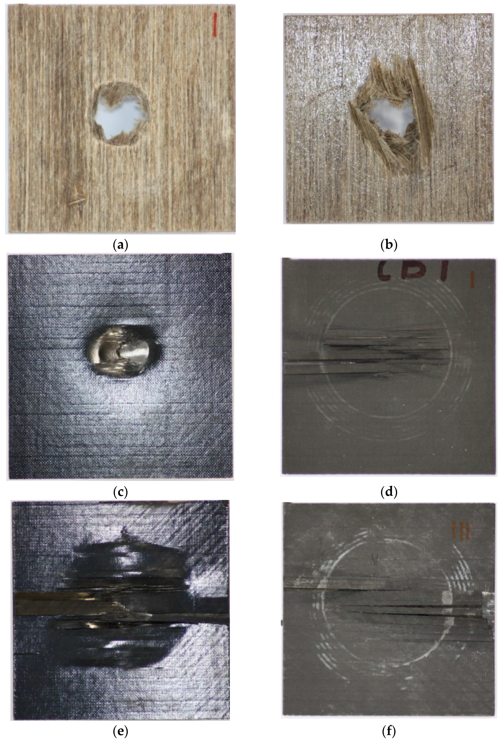
The plain flax fibre epoxy impact samples showed complete drop weight penetration in all samples, shown in Figure 10a,b. Combined large cracks can be seen on the reverse images; the samples were more likely to suffer radial fractures upon penetration [13] (pp. 559–567). The damage is within an area similar to the diameter of the impact tup.
The topside of the flax fibre impact samples experiences fibre breakage spanning the circumference of the impact zone, shown in Figure 10a. The impact tup then folded the topmost layers through the penetration zone.
The carbon impact samples shown in Figure 10c,d only saw bent fibres around the impact dent as the tup did not penetrate. The tup did split the upper layer, but no signs of large delamination are present on the topmost layer.
However, the bottommost layers of the carbon fibre impact samples saw push out delamination, shown in Figure 10c,d. The rearmost layer has delaminated in 2 mm wide splinters, rising in an opposing pattern over the rear of the impact site, in some cases the first layer behind the outermost rear layer has seen fibres protrude beyond the eighth layer.
The hybrid samples, pictured in Figure 10e,f, show the impact site with a wide area of damage suspected to be the flax fibres crushing and the matrix cracking heavily internally leading to delamination from the carbon. As with the carbon only samples, there is excessive push out delamination on the rearmost layer, with a large amount of fibre breakage and debonding.
3.4.2. Visual Observations of Damage under Flexural Loading
The flax/epoxy samples all displayed crushed fibres around the point of the loading nose contact, where the fibres are under compression. This is shown in Figure 11a above with arrows marking the compressive and tensile load paths, including Figure 11b. The compressed topmost layers see excessive random delamination and matrix cracking. The bottom layers under tension see delamination and more fibre breakage.
The topmost layer of carbon fibre under tension, shown in Figure 11c, suffers massive delamination from the primary body, which begins to experience a greater form of fibre breakage and debonding until the primary layers under tension are shown to have an explosive failure. The hybrid samples in Figure 11d show minimal external damage visible using non-destructive testing methods.
4. Conclusions
The mechanical properties (low-velocity impact and flexural) of flax/epoxy, carbon/epoxy and flax-carbon/epoxy hybrid composites were experimentally studied. This study has clearly suggested that carbon fibre hybridisation onto flax/epoxy composites can contribute a significant improvement in impact damage behaviour and flexural strength and modulus.
Through damage analysis, the hybrid composite displayed similar impact characteristics to the plain carbon/epoxy composites, far exceeding the performance of plain flax/epoxy composites alone. It was also evidenced that the natural fibres such as flax also dampened the harmonic resonance during the test. This is a significant achievement in providing the potential of natural fibre hybrid composites in semi-structural and structural light-weight applications.
The damage characterisation through SEM imaging has shown the various failure modes of the plain flax/epoxy and flax-carbon/epoxy hybrid composites, such as the shock loading of flax fibre cores in falling weight impact and flexural loading scenarios.
Author Contributions
M.C. contributed in design, conducting experimental procedures and compiling the results as well as writing the preliminary report. H.N.D. provided the overall guidance (supervision) including the design of the study, general interpretation of the results and writing of the paper.
Funding
This research received no external funding.
Conflicts of Interest
The authors declare no conflict of interest.
References
- European Comission. Available online: https://ec.europa.eu/clima/policies/transport/vehicles/cars_en (accessed on 25 March 2019).
- Dhakal, H.; Zhang, Z.; Guthrie, R.; MacMullen, J.; Bennett, N. Development of flax/carbon fibre hybrid composites for enhanced properties. Carbohydr. Polym. 2013, 96, 1–8. [Google Scholar] [CrossRef] [PubMed] [Green Version]
- Composites Evolution. Available online: https://compositesevolution.com/news/carbonflax-hybrid-automotive-door-on-display-at-jec-world-featuring-composites-evolutions-biotex-flax/ (accessed on 25 March 2019).
- Pil, L.; Bensadoun, F.; Pariset, J.; Verpoest, I. Why are designers fascinated by flax and help fibre composites? Compos. Part A Appl. Sci. Manuf. 2016, 83, 193–205. [Google Scholar] [CrossRef]
- Dhakal, H.N.; Skrifvars, M.M.; Adekunle, K.; Zhang, Z.Y. Falling weight impact response of jute/methacrylated soybean oil bio-composites under low velocity impact loading. Compos. Sci. Technol. 2014, 92, 134–141. [Google Scholar] [CrossRef] [Green Version]
- Mahboob, Z.; Sawi, I.E.; Zdero, R.; Fawaz, Z.; Bougherara, H. Tensile and compressive damaged response in flax fibre reinforced epoxy composites. Compos. Part A Appl. Sci. Manuf. 2017, 92, 118–133. [Google Scholar] [CrossRef]
- Sarasini, F.; Tirillò, J.; D’Altilia, S.; Valente, T.; Santulli, C.; Touchard, F.; Chocinski-Arnault, L.; Mellier, D.; Lampani, L.; Gaudenzi, P. Damage tolerance of carbon/flax hybrid composites subjected to low velocity impact. Compos. Part B Eng. 2016, 91, 144–153. [Google Scholar] [CrossRef]
- Dhakal, H.N.; Sarasini, F.; Santulli, C.; Trillò, J.; Zhang, Z. Effect of basalt fibre hybridisation on post-impact mechanical behaviour of hemp fibre reinforced composites. Compos. Part A Appl. Sci. Manuf. 2015, 75, 54–67. [Google Scholar] [CrossRef]
- Kumar, S.C.; Arumugam, V.; Dhakal, H.N.; John, R.R. Effect of temperature and hybridisation on the low velosity impact behaviour of hemp-basalt/epoxy composites. Compos. Struct. 2015, 125, 407–416. [Google Scholar] [CrossRef]
- Woigk, W.; Fuentesc, C.A.; Riond, J.; Hegemanne, D.; van Vuurec, A.W.; Dransfeldb, C.; Masania, K. Interface properties and their effect on the mechanical performance of flax fibre thermoplastic composites. Compos. Part A Appl. Sci. Manuf. 2019, 122, 8–17. [Google Scholar] [CrossRef]
- Hexcel. Available online: http://www.hexcel.com/Resources/DataSheets/Prepreg (accessed on 25 March 2019).
- ASTM International. Standard Test Method for Measuring the Damage Resistance of a Fiber-Reinforced Polymer Mareix Composite to a Drop-Weight Impact Event; ASTM International: West Conshohocken PA, USA, 2012. [Google Scholar]
- Sarasini, F.; Tirillo, J.; Ferrante, L.; Sergi, C.; Russo, P.; Simeoli, G.; Cimino, F.; Rosaria Ricciardi, M.; Antonucci, V. Quasi-static and low-velocity impact behaviour of intraply hybrid flax/basalt composites. Fibers 2019, 7, 26. [Google Scholar] [CrossRef]
- Russo, P.; Simeoli, G.; Vitiello, L.; Fillippone, G. Bio-polyamide 11 hybrid composites reinforced with basalt/flax interwoven fibres: A tough green composite for semi-structural applications. Fibers 2019, 7, 41. [Google Scholar] [CrossRef]
- Dhakal, H.N.; Zhang, Z.Y.; Richardson, M.O.; Errajhi, O.A. The low velocity impact response of non-woven hemp fibre reinforced unsaturated polyester composites. Compos. Struct. 2007, 71, 559–567. [Google Scholar] [CrossRef]
Figure 1.
Impact test traces (a) force vs. deflection trace, (b) force vs. time trace, (c) energy vs. time.
Figure 1.
Impact test traces (a) force vs. deflection trace, (b) force vs. time trace, (c) energy vs. time.

Figure 2.
Force versus deformation traces obtained from flexural testing of flax/epoxy, carbon/epoxy and flax-carbon/epoxy hybrid composites.
Figure 2.
Force versus deformation traces obtained from flexural testing of flax/epoxy, carbon/epoxy and flax-carbon/epoxy hybrid composites.

Figure 3.
SEM images of fracture surface morphology of plain flax composites failed under impact loading at different magnifications (a) fibre debonding and bending; (b) fibre breakage.
Figure 3.
SEM images of fracture surface morphology of plain flax composites failed under impact loading at different magnifications (a) fibre debonding and bending; (b) fibre breakage.

Figure 4.
SEM images of fracture surfaces of flax alone composites failed under flexural loading (a) showing tension and compressive load path; (b) debonding and large part of matrix debulked; (c) fibre bending, fibre breaks and matrix debulking shown at both compression and tension sides.
Figure 4.
SEM images of fracture surfaces of flax alone composites failed under flexural loading (a) showing tension and compressive load path; (b) debonding and large part of matrix debulked; (c) fibre bending, fibre breaks and matrix debulking shown at both compression and tension sides.

Figure 5.
SEM images of the outermost layer of carbon fibre impact samples (a) fibre breakage at 150× magnification; (b) fibre breakage site at an enhanced 300× magnification.
Figure 5.
SEM images of the outermost layer of carbon fibre impact samples (a) fibre breakage at 150× magnification; (b) fibre breakage site at an enhanced 300× magnification.

Figure 6.
Plain carbon/epoxy composites under 3-point bending testing sample at different magnifications (a) matrix cracking and fibre bending at 75× magnification; (b) matrix cracking and fibre bending at an enhanced 150× magnification.
Figure 6.
Plain carbon/epoxy composites under 3-point bending testing sample at different magnifications (a) matrix cracking and fibre bending at 75× magnification; (b) matrix cracking and fibre bending at an enhanced 150× magnification.

Figure 7.
SEM images of flax/carbon/epoxy hybrid composites surfaces failed under impact loading at different magnifications. (a) flax fibres intersecting a carbon fibre layer at 151× magnification; (b) enhanced view of flax fibres intersecting a carbon fibre layer at 300× magnification; (c) fibre pull-out.

Figure 8.
SEM images of flax/carbon/epoxy hybrid composites at different magnifications showing (a) tension and compression pathways, (b) delamination between carbon and flax fibres, (c) delamination and matrix cracking.
Figure 8.
SEM images of flax/carbon/epoxy hybrid composites at different magnifications showing (a) tension and compression pathways, (b) delamination between carbon and flax fibres, (c) delamination and matrix cracking.

Figure 9.
Post-impact test underside damage (a) flax fibre epoxy, (b) carbon fibre epoxy, (c) carbon-flax/epoxy hybrid composites.
Figure 9.
Post-impact test underside damage (a) flax fibre epoxy, (b) carbon fibre epoxy, (c) carbon-flax/epoxy hybrid composites.

Figure 10.
Damage on impacted front and rear surface of flax, carbon and flax/carbon epoxy hybrid composites (a) flax front surface, (b) flax rear surface, (c) carbon front and (d) carbon rear, (e) carbon/flax hybrid front, (f) carbon/flax hybrid rear surface.
Figure 10.
Damage on impacted front and rear surface of flax, carbon and flax/carbon epoxy hybrid composites (a) flax front surface, (b) flax rear surface, (c) carbon front and (d) carbon rear, (e) carbon/flax hybrid front, (f) carbon/flax hybrid rear surface.

Figure 11.
Failed samples under flexural loading (a) compressed plain flax/epoxy, (b) split outer layer of plain flax/epoxy under tension, (c) plain carbon/epoxy damage, (d) flax-carbon/epoxy hybrid composites.
Figure 11.
Failed samples under flexural loading (a) compressed plain flax/epoxy, (b) split outer layer of plain flax/epoxy under tension, (c) plain carbon/epoxy damage, (d) flax-carbon/epoxy hybrid composites.


Table 1.
Test specimen layup characteristics.
| Specimen | Layers | Stacking Sequence (°) | Material Sequence |
|---|---|---|---|
| Flax/epoxy | 8 | 0/+45/−45/90/90/−45/+45/0 | F8 |
| Carbon/epoxy | 8 | 0/+45/−45/90/90/−45/+45/0 | C8 |
| Flax-carbon/epoxy hybrid | 8 | 0/+45/−45/90/90/−45/+45/0 | C2F4C2 |
Table 2.
Average flexural properties obtained from three-point bending testing.
| Specimen | Peak Force (N) | Flexural Strength (MPa) | Flexural Modulus (GPa) | Deformation at Peak Force (mm) |
|---|---|---|---|---|
| Flax/epoxy | 115.75 (±6.61) | 95.66 (±5.46) | 4.78 (±1.16) | 4.01 (±0.32) |
| Flax-carbon/epoxy hybrid | 553.30 (±61.63) | 425.87 (±50.93) | 17.90 (±0.31) | 3.96 (±0.22) |
| Carbon/epoxy | 532.40 (±9.55) | 464.65 (±7.89) | 52.82 (±2.16) | 1.16 (±0.13) |
© 2019 by the authors. Licensee MDPI, Basel, Switzerland. This article is an open access article distributed under the terms and conditions of the Creative Commons Attribution (CC BY) license (http://creativecommons.org/licenses/by/4.0/).
Share and Cite
MDPI and ACS Style
Chapman, M.; Dhakal, H.N. Effects of Hybridisation on the Low Velocity Falling Weight Impact and Flexural Properties of Flax-Carbon/Epoxy Hybrid Composites. Fibers 2019, 7, 95. https://0-doi-org.brum.beds.ac.uk/10.3390/fib7110095
AMA Style
Chapman M, Dhakal HN. Effects of Hybridisation on the Low Velocity Falling Weight Impact and Flexural Properties of Flax-Carbon/Epoxy Hybrid Composites. Fibers. 2019; 7(11):95. https://0-doi-org.brum.beds.ac.uk/10.3390/fib7110095
Chicago/Turabian StyleChapman, Matthew, and Hom Nath Dhakal. 2019. "Effects of Hybridisation on the Low Velocity Falling Weight Impact and Flexural Properties of Flax-Carbon/Epoxy Hybrid Composites" Fibers 7, no. 11: 95. https://0-doi-org.brum.beds.ac.uk/10.3390/fib7110095
Note that from the first issue of 2016, this journal uses article numbers instead of page numbers. See further details here.