Terahertz Hollow Core Antiresonant Fiber with Metamaterial Cladding
by
 , , , , and
Jakeya Sultana
1,* ,
,
Md. Saiful Islam
1,2,* ,
,
Cristiano M. B. Cordeiro
2,3,
Alex Dinovitser
1,
Mayank Kaushik
1,
Brian W.-H. Ng
1 and
Derek Abbott
1 1
School of Electrical & Electronic Engineering, University of Adelaide, Adelaide, SA 5005, Australia
2
Institute for Photonics & Advanced Sensing (IPAS), University of Adelaide, Adelaide, SA 5005, Australia
3
Institute of Physics, University of Campinas, Campinas 13083-859, Brazil
*
Authors to whom correspondence should be addressed.
Fibers 2020, 8(2), 14; https://0-doi-org.brum.beds.ac.uk/10.3390/fib8020014
Submission received: 8 January 2020
/
Revised: 30 January 2020
/
Accepted: 4 February 2020
/
Published: 17 February 2020
(This article belongs to the Special Issue Microstructured Optical Fibers and Applications)
Abstract
:A hollow core antiresonant photonic crystal fiber (HC-ARPCF) with metal inclusions is numerically analyzed for transmission of terahertz (THz) waves. The propagation of fundamental and higher order modes are investigated and the results are compared with conventional dielectric antiresonant (AR) fiber designs. Simulation results show that broadband terahertz radiation can be guided with six times lower loss in such hollow core fibers with metallic inclusions, compared to tube lattice fiber, covering a single mode bandwidth (BW) of 700 GHz.
1. Introduction
Terahertz radiation [1] presents a new frontier with plenty of technical applications and fundamental research challenges for sensing, including label-free and noninvasive molecular detection, hybridization of DNA, security scanning, pharmaceutical drug testing, and high-speed short-range optical communications [2,3,4,5,6,7]. Terahertz also has potential for biomedical spectroscopy, with low energy that is completely non-ionizing, a photon energy that is lower than that of mid-IR radiation, yet with stronger polar molecular interactions than microwave radiation [8,9,10,11]. Despite all of the potentiality of terahertz, research in this field still has much to accomplish, as most of the present terahertz systems are expensive and bulky, and lack the availability of low loss waveguides, common at other wavelengths. As a primary solution for low loss terahertz transmission, hollow waveguides [12,13,14,15,16,17] are of interest because the terahertz pulses are mostly guided in the air-core, significantly reducing the material loss, and therefore the designs are less dependent on material absorption. Guiding broadband terahertz pulses using hollow metal or hollow metal coated dielectric waveguides [18,19,20], hollow dielectric waveguides [21,22], and dielectric-coated metallic hollow waveguides [23,24,25,26,27,28,29,30,31,32] have been demonstrated.
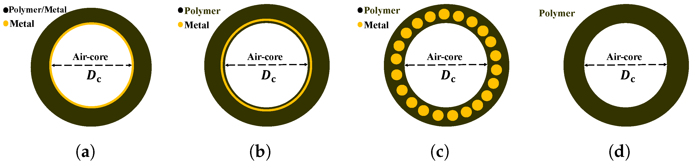
In 1999, broadband sub-picosecond pulses of terahertz radiation were first coupled into a 4 mm long stainless steel hypodermic needle [19], and in 2000, Gallot et al. extended the idea to a 25 mm long, brass circular hollow waveguide [5]. The measured power absorption coefficient was 300 dB/m at 1 THz for the stainless steel waveguide [19]. Metal surface roughness produced during extrusion of the needle and inflexibility of the metal tube are the main limitations. A hollow polymer based inner metal coated waveguide solves these problems having a smooth metal coating inside the thin polymer wall. A copper-coated hollow polycarbonate waveguide exhibited the lowest loss of dB/m at m (∼1.9 THz) for a 3 mm bore fiber [23]. A simple schematic diagram of a metal hollow waveguide (HWG) is shown in Figure 1a. Some of the lowest transmission losses in the terahertz region were achieved with silver coating inside a flexible thin silica-glass tube, with a loss of –8 dB/m. Another attribute of circular hollow metal waveguide design is that the TE11 mode is the dominant mode and is excited only by a linearly polarized wave [18,19], which is convenient as most optical terahertz sources are linearly polarized. However, the TE01 mode shows the lowest loss in metal waveguide, though specialized coupling is required for linearly polarized terahertz source.
The losses in copper hollow waveguides can be further reduced by a dielectric coating of the correct optical thickness, deposited over the metallic layer [23]. Using a similar concept for further reducing the transmission loss to 0.95 dB/m at 2.5 THz, a silver/polystyrene-coated hollow glass waveguide (Ag/PS HGW) was experimentally characterized [24,25]. The 90 cm long waveguide was fabricated with a mm bore coated with a 8.2 m thick polystyrene film. There is an obvious difference between the dielectric coated and bare metal hollow waveguide on the basis of dominant mode. Adding a thin dielectric film into the inner surface of a metallic waveguide transitions the dominant transverse TE01 mode for azimuthal excitation of terahertz wave to a hybrid HE11 mode. The silver/polystyrene hollow wabeguide (Ag/PS HGW) exhibits a HE11 hybrid dominant mode [24], whereas the silver-only [24] or copper-only [23] hollow waveguides exhibit a transverse TE01 mode requiring azimuthal excitation by the incoming terahertz wave. Also, the thickness of the PS film determines whether the hybrid HE11 mode or the transverse TE01 mode exhibits the lowest loss [25]. Moreover, the dielectric layer on the inner surface of the metallic waveguide is essential to support low-loss hybrid modes, with minimal affect on dispersion [29], and is advantageous for low loss terahertz transmission. In 2010, Tian et al. [30] theoretically and experimentally demonstrated a dual cylindrical metallic grating-cladding polymer hollow terahertz waveguide where the attenuation constant of the linear polarization HE11 mode can be reduced to 0.62 dB/m with a 5.0 mm copper tube bore diameter and 50 m polyethylene thickness. This waveguide is composed of copper cylindrical gratings together with high-density polyethylene tubing, making the waveguide rather complex, requiring fabrication using liquid-phase chemical deposition techniques [23,25] to coat the dielectric film over the metal, and a wet chemistry method to deposit the metal film. A simple schematic diagram of this HWG is shown in Figure 1b.
An alternative approach proposed by [31,32,33,34], is to embed sub-wavelength metal wires within dielectric materials for guiding terahertz radiation. A possible fiber fabrication technique is to co-draw metal and dielectrics [34] or via use of printed dielectric waveguides with air holes in the cladding, with later insertion of metal wires into the holes [32]. A simple schematic diagram of this hybrid cladded metal HWG is shown in Figure 1c.
A particular new class of dielectric fiber [35,36,37,38,39,40,41], namely, antiresonant (AR) fiber, has attracted attention because of its simple structure and desirable guiding properties. The simplified structure features a negative core curvature, a non-touching core boundary, and a single tube cladding layer [38,39,40], often also named the Tube Lattice Fiber (TLF). The negative core curvature enhances the coupling inhibition between the core and cladding modes [37], whereas the non-touching core boundary assists in the reduction of the loss caused by the Fano-resonance [15]. Recently, nodeless single layer negative curvature Hollow Core Antiresonant Photonic Crystal Fiber (HC-ARPCF) was proposed and experimentally demonstrated for terahertz wave guidance [38]. The HC-ARPCF is a relatively simple design for fabrication, using commercially available PMMA (polymethyl-methacrylate) and was experimentally validated for terahertz guidance with excellent mode qualities and controllable bandwidth. Moreover, the capillary tubes provide resonant coupling from the core’s Higher Order Modes (HOMs), to provide dissipation and suppression of HOMs [42]. The difference of propagation loss between the fundamental core mode and the higher order core modes can be increased by a proper choice of cladding features, thus allowing microstructured fibers to be effectively single mode [42]. In 2015, Lu et al. reported a Zeonex based fiber with the lowest loss of 1 dB/m at low terahertz frequency [39]. In 2018, Nazarov et al. [40] demonstrated the possibility of manufacturing a single-mode flexible waveguide, with a loss of 7 dB/m within a – THz bandwidth.
In this paper, we apply this concept to tube lattice fiber by adding sub-wavelength metal wires into the cladding, creating a metamaterial, and we compare its performance against tube lattice fiber. Numerical study of fundamental and HOMs of the proposed fiber shows wide-range single mode guidance, strong light confinement and six times lower loss than the tube lattice fiber. We also address the impact of waveguide modes on transmission characteristics for AR fiber with and without metal wires. The results show that the LP11 is influenced mostly by changes to the cladding pattern. The proposed structure with a hollow core is a potential candidate for a low loss terahertz waveguide. A polymer–metal fiber drawing technique can be used to fabricate the proposed fiber [34] or a postprocessing technique can be used to insert the metal in a liquid state with the fiber already made [43].
2. Design Methodology
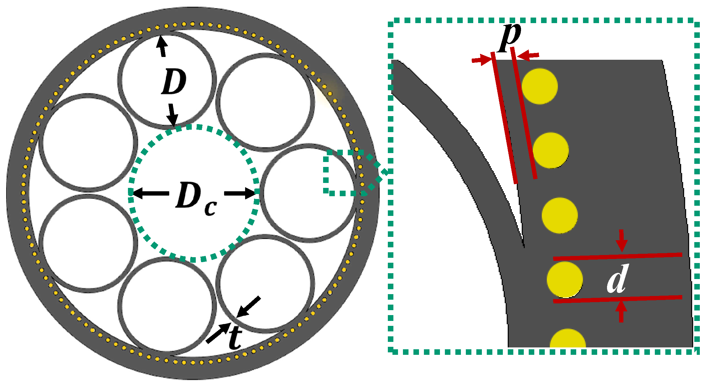
The proposed structure can be fabricated with seven non-touching, circular, dielectric antiresonant tubes, where the cladding dielectric layer contains metal wires, as illustrated in Figure 2, employing Zeonex dielectric and aluminum metal. The AR fibers with metal-wire inclusions have a core diameter (Dc) of 3 mm, inner dielectric antiresonant tube diameter (D) of mm, and a Zeonex wall thickness (t) of mm. The core diameter is defined as the maximum circle diameter, as illustrated by the dashed green circle illustrated in the figure, that can be inscribed inside the core. With constant core diameter, the avoids the mode contamination in the air-core and assists in single mode guidance over a board frequency range. It is important to mention that the wall thickness, mm, is chosen to give a first AR transmission band centered at approximately 1 THz in this model. The metal wires are inserted at the optimal distance p from the inside of the mm thick Zeonex cladding layer. The cladding layer not only provides mechanical support for the metal wires, also supports to confine the mode guidance in the air-core. The key parameters that determine the performance of the AR fibers with metal-wire inclusions are the innermost dielectric layer thickness p, and diameter d of metal wires and Figure 2 indicates those parameters. The complex refractive index of aluminum at 1 THz is –i561.13 [44]. Low bulk material absorption loss of Zeonex is 0.02 cm and constant refractive index of 1.5352 in a 0.1 to 4.5 THz frequency range [45].
The light guidance of the proposed fiber occurs via inhibited coupling between core and cladding modes [16,17], or on the basis of the Anti-Resonant Reflecting Optical Waveguide (ARROW) model [46]. The spectral transmission of the ARROW waveguide model manifests as multi-band transmissions such that when a frequency satisfies the resonant condition of resonator (resonance frequency), light will leak out from the hollow core. Light leakage from the core at a resonance frequency creates a high transmission loss characteristic of a transmission dip. In the inhibited coupling theory, coupling between core mode and cladding mode creates a high loss at the resonance frequency. The resonance frequency (fm) mainly depends on the cladding tube thickness t [47] and is calculated from the following equation [48]:
where nclad represents the refractive index of the cladding material, Zeonex, in this work. The nco indicates the refractive indices of the core material, air here, and m is an integer, representing the order of resonance. To perform the numerical simulations, we used a finite-element based “Eigenvalue solver” (COMSOL Multiphysics).
Methodology of Characterizing the AR Fibers With Metal-Wire Inclusions
The loss contribution for HC-ARPCFs in the terahertz spectrum is the confinement loss that arises when light from the source is not confined to the core region and leaks out towards the cladding. In fiber geometry, leakage can arise when light couples into the polymer webs, or into the small gaps between the tubes and the external fiber jacket. In numerical calculations, confinement loss is proportional to the imaginary part of complex refractive index of the guided mode that can be calculated by [49],
where, indicates the confinement loss, f specifies the operating frequency, and Im (eff) represents the imaginary part of the effective refractive index. The confinement loss becomes most significant at the resonance frequency range where the fraction of power in the core is also low.
The fraction of power (P) confined in sample area, for example in core or in the bulk material, is used to quantify the amount of overlap between light and material and follows the equation [2,50],
where denotes the real part, , and , are the transverse electric and magnetic field of the guided mode, respectively. In this simulation, the integration of the numerator is carried out for the core region and the integration of denominator is performed over the whole fiber region.
3. Results and Discussion
3.1. Effect of Metal Wire Number
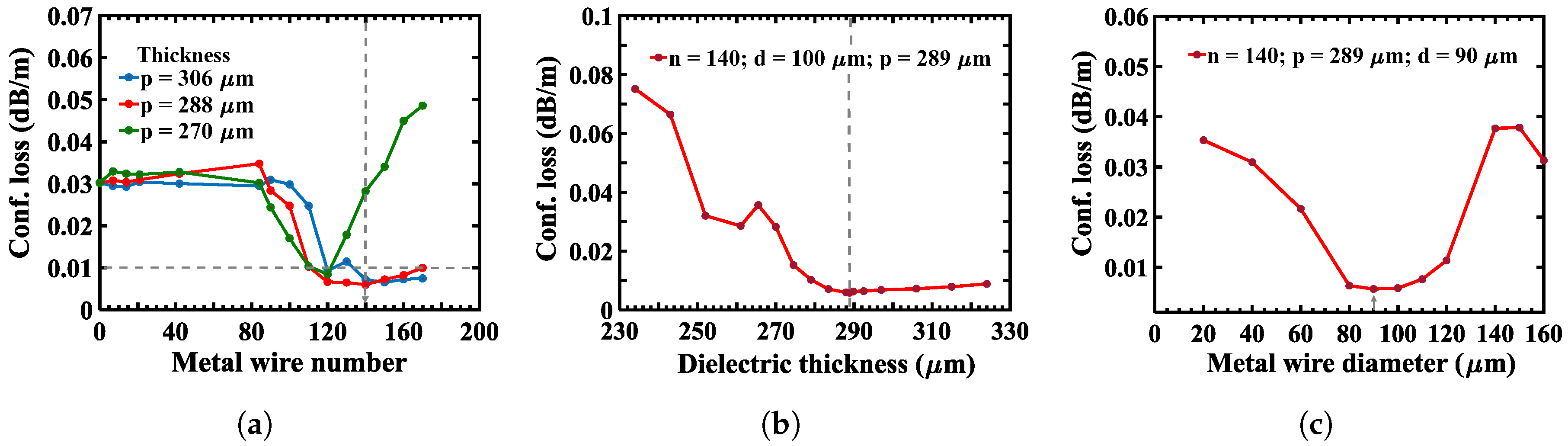
The affect of the metal wire number n on the confinement loss of the waveguide is investigated and shown to be critical for design optimization. Figure 3a shows confinement loss of a LP01-like fundamental mode as a function of sub-wavelength metal wire number for the innermost dielectric layer thickness m, 288 m, and 270 m. Fibers with a small number of metal wires in the Zeonex cladding suffer a similar confinement loss to an all-dielectric cladding layer, behaving like dielectric AR fibers. The confinement loss of the LP01-like fundamental mode varies greatly when the metal wire number is more than 100 for each cases (, 288 and 270 m). The losses are significantly reduced to dB/m at 1 THz where there are more than 120 metal-wires of diameter m and innermost dielectric layer thickness m. However, with the number of metal wires increasing, the cladding becomes more metallic in nature, and the confinement loss increases. The optimized structure has 140 subwavelength aluminum wires as indicated with an arrow in Figure 3a.
3.2. Effect of Inner Cladding Dielectric Layer Thickness and Metal Wire Diameter
The transmission efficiency is optimized with number of metal wires while diameter d is varied between 20 m and 160 m, and the innermost dielectric layer thickness, p is varied from 230 to 330 m, as illustrated in Figure 3b,c. It can be seen from Figure 3b that the innermost dielectric layer thickness plays an important role in minimizing and maximizing the confinement loss of the LP01-like fundamental mode. The minimum loss of dB/m at 1 THz for the LP01-like fundamental mode can be found at m for m and . When the innermost dielectric layer thickness p is reduced to less than 270 m, the confinement loss increases rapidly due to Ohmic loss of the metal, that plays the dominant role in the increase of confinement loss. In that case, the AR fiber with metal inclusions behaves like an AR fiber with an internal metal coating.
We also numerically simulate the confinement loss as a function of metal wire diameter d in Figure 3c where the metal wire number n = 140 and innermost dielectric layer thickness m. When the d is less than 80 m, the confinement loss of the LP01-like fundamental mode increases and the fiber behaves like a pure dielectric waveguide. In contrast, when the d is more than 140 m, the confinement loss of the LP01-like fundamental mode increases due the metal. Based on the above numerical simulation, we consider , m and m as near optimum, and analyze the proposed fiber.
3.3. Comparison between Dielectric AR Fiber with and without Metal Wire Inclusion
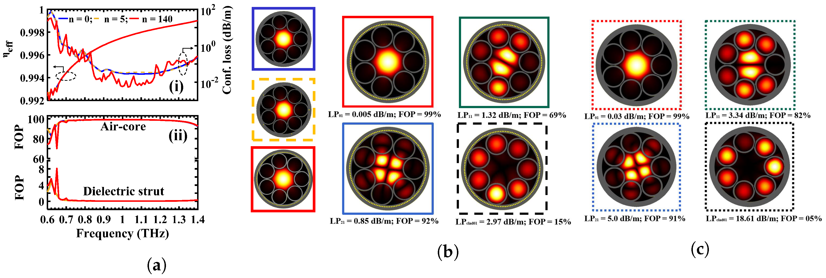
The LP01-like fundamental mode field intensity of AR fibers with metal-wire inclusions is shown rightmost in Figure 4a for metal wire numbers, , 5 and 140. The fibers have a uniform wire diameter m and fixed dielectric thickness between the internal side of the aluminum wire and inner surface of dielectric cladding m. Figure 4a(i) shows the effective refractive index and confinement loss of the LP01-like fundamental mode as a function of frequency. The effective refractive index of the air-core is similar for AR fibers with , 5 and 140 metal-wire inclusions as shown in Figure 4a(i). The confinement loss for AR fibers with around 140 metal-wire inclusions shows comparatively lower loss than for lower numbers of metal-wire inclusions. The blue, yellow and red line indicate the AR fibers with 0, 5, and 140 metal-wire inclusions, respectively. The simulation has been performed within the low loss region around – THz with the step size of THz. A minimum confinement loss of dB/m occurs at THz for dielectric AR fibers (), where AR fiber with 140 metal wire inclusions shows dB/m at THz, which is six times lower than dielectric AR fibers. We have shown in Figure 4a that a single layer of optimized sub-wavelength metal wires in a host dielectric environment is sufficient to provide good guidance with the same properties. Figure 4a(ii) shows the fraction of power both the air core and dielectric strut adjacent to the core. Approximately of the power is transmitted through the air-core for all of the AR fibers with metal-wire inclusions, with less than through the antiresonant dielectric struts. Therefore, a very small fraction, less than of the power, penetrates through the Zeonex layer to reach the metal inclusions. However, even this small penetration makes an impact on the loss for different numbers of metal wires.
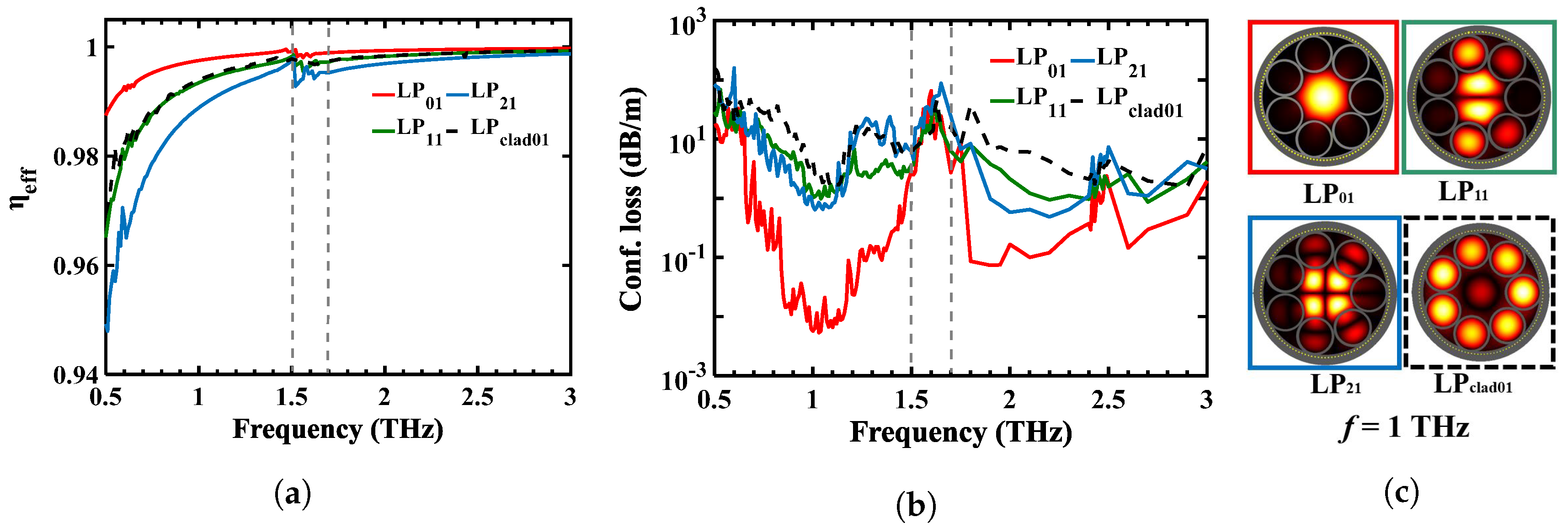
The mode field intensities shown in Figure 4b,c are the Linearly Polarized (LP) modes derived by solving scalar Maxwell’s equations under weakly-guided conditions [51] and experimentally characterized by [52]. We took four LP group modes and analyzed the optical properties on the AR fiber with metal wire inclusions and without metal wire inclusions. Mode field intensity of fundamental core mode (LP01), higher order core modes (LP11, LP21), and cladding mode (LPclad01) at THz are considered. In the HC-ARF, the core modes localize in the air-core only where the cladding mode localizes in cladding-air holes or dielectric cladding wall [53]. In our work, we define the light localization in cladding–air holes as a cladding mode. Note that the true vectorial eigenmode of HE11 is in LP01 mode. Also, the TM01, HE21, and TE01 modes are in the LP11 mode group. From Figure 4b,c, we can see that the AR fiber with metal wire inclusions has a stronger light confinement in the air-core. For LP01, LP21 and LPclad01 modes, the FOPs in core with metal are higher than that of without metal wire inclusions; however, for the LP11, the result is opposite: 69% for the AR fiber with metal wire inclusions. Because approximately 0.2% of power is absorbed in dielectric strut which is higher than that of without metal wire inclusions (0.12%). The study also confirms that the overall confinement loss for all four modes decreases with the metal wire inclusions. It is assumed that the dielectric coating over the metal wire inclusions enhances the reflectivity of the metal-wire inclusions and reduce the loss. Moreover, the LP11 mode is also sensitive to the cladding pattern. The LP11 provides low loss between the HOMs in AR fibers without metal-wire inclusions. Only inserting the metal wire inclusion at the cladding, the LP21 provides low loss between the HOMs. The single mode guidance ratio are 170 and 112 for AR fibers with metal-wire inclusions and without metal-wire inclusions, respectively. The loss ratio of lowest HOM and the fundamental LP01 (the LP21/LP01 and LP11/LP01 for AR fibers with metal-wire inclusions and without metal-wire inclusions, respectively) results in single mode guidance. The loss ratio increases to maximum at but is not shown in this manuscript. Here, the metal wire inclusions increase the single mode guidance by a factor of 58 (170–112) as compared to no metal-wire inclusions at 1.03 THz. It is important to note that diameter and position of the metal wire inclusions are optimized.
The real part of effective index (eff) for the LP11 and LPclad01 in Figure 5a maintains the same phase to avoid mode contamination over the frequency range to 3 THz. To precisely evaluate the propagation properties we use a frequency step size of THz. Figure 5b shows the corresponding simulated confinement loss of the guided modes. The confinement loss difference between LP01-like fundamental mode and lowest HOM defines the single mode operation window between 0.8 and 1.3 THz. However, from 0.8 to 1.3 THz, the confinement loss is lower than 0.1 dB/m, whereas for the other frequency ranges (0.5–0.8 THz and 1.3 1.6 THz), the confinement loss is not relatively low. The variation of confinement loss in the single mode operation range is not a smooth vary as the innermost dielectric layer introduces interference peak [26] in the single mode operation range. The resonance frequency lies at approximately 1.55 THz where the LP01-like fundamental mode is coupled to LPclad01 and it is difficult to differentiate the LP01-like fundamental mode from the LPclad01 mode. Also, around the resonance frequency, mode contamination arises. Above 1.6 THz, mode contamination arises multi-mode propagation. The simulation also indicates that the minimum confinement loss for the LP01-like fundamental mode is dB/m at 1 THz. The LP21 provides the lowest HOM confinement loss of dB/m at 1 THz. The ratio of higher mode suppression is nearly 130 at 1 THz. The simulation has been performed for a uniform wire diameter m and innermost dielectric layer thickness m and . A number of HOMs introduced in a large core diameter (3 mm), giving rise to mode contamination. To suppress the mode contamination in a large core fiber, we normalize the tube diameter as a ratio of . At , making it possible to reduce the influence of HOMs in the core. The ratio of assists in mode coupling between the LP11 and LPclad01 to prevent mode contamination in core as shown in Figure 5c. That ratio determines the single mode operation of the fiber over a board frequency range.
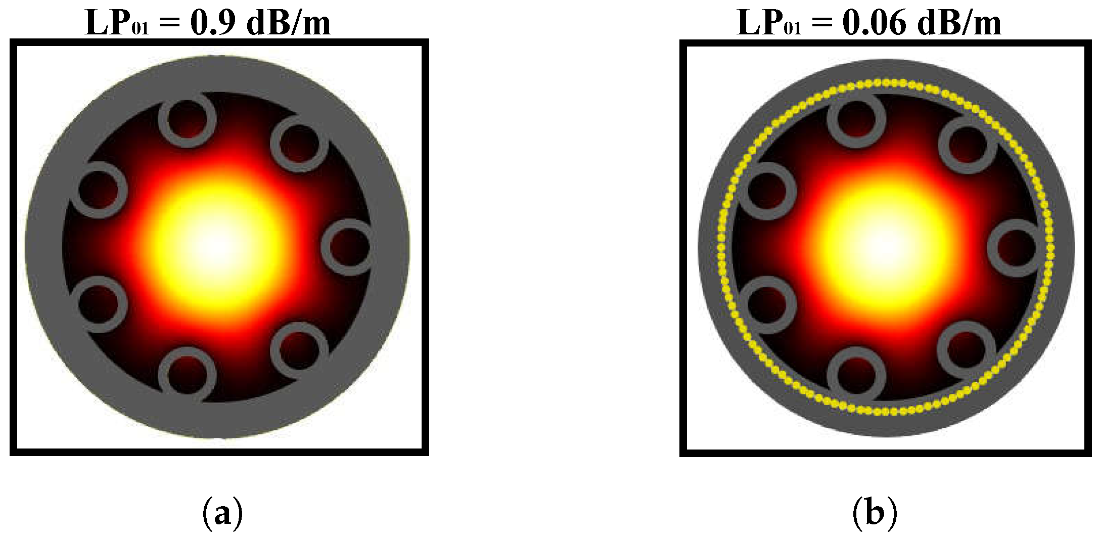
The fundamental mode field distribution for AR fiber with and without metal wire inclusions are included in Figure 6, for , to show the impact of adjacent tube gaps on confinement loss. When the antiresonant tubes are small, such that , light leaks through the large gap between two adjacent antiresonant tubes. The small distance from air-core to cladding wall hence increases the confinement loss to 0.9 dB/m for the LP01-like fundamental mode at 1 THz as shown in Figure 6a. The metal wires in Figure 6b demonstrate very clear influence on the leakage through the gap between adjacent tubes and the cladding structure. It reduces the confinement loss to 0.06 dB/m that is 15 times lower than the dielectric fiber.
4. Conclusions
We propose AR fibers with metal-wire inclusions for low loss terahertz guidance, and present optimized solutions for increasing terahertz transmission. Our designs can be implemented to effectively confine the guided wave through a large hollow core with lower loss than previously possible. In this paper, we compare the AR fiber with and without metal wire inclusions for same dimensions and investigate the effect of metal wires on the confinement loss. We explain and illustrate how the metal inclusions serve to better confine the desired core modes, while minimizing material losses. The AR fiber with optimized metal-wire inclusions exhibits six times lower loss compared with a pure dielectric AR fiber, making it promising for terahertz transmission. The multimode nature of large core diameter terahertz fibers has to be suppressed by tuning the antiresonant tubes to act as a single mode fiber in the whole transmission region. The metal wires maintain the optical properties of refractive index and mode field pattern, while lowering the confinement loss. This work, aiming at improving the loss performance of terahertz waveguides, finds that metal wires inside the cladding dielectric of antiresonat tubes form a promising research direction for future work. The AR fibers with metal wire inclusions offers potential application in terahertz transmission and imaging due to the low loss single mode operating window, as well as at the same time in sensing due to the possibility of achieving a high loss resonance peak.
Author Contributions
J.S. carried out the study and wrote the paper. M.S.I., C.M.B.C., and A.D., assisted in conceptualization of results. All authors assisted in interpretation of results and in proofing the material. M.K., B.W.-H.N., and D.A. supervised the study. All authors have read and agreed to the published version of the manuscript.
Funding
This work was supported by the Australian Research Council (ARC) Grant DP170104981 and in part by the Sao Paulo Research Foundation (FAPESP) under grant 2018/10409-7.
Conflicts of Interest
The authors declare no conflicts of interest.
Abbreviations
The following abbreviations are used in this manuscript:
| AR | Antiresonant |
| HWG | Hollow Waveguide |
| LP | Linearly Polarized |
| FOP | Fraction of Power |
| HOM | Higher Order Mode |
| HC-ARPCF | Hollow Core Antiresonant Photonic Crystal Fiber |
References
- Tonouchi, M. Cutting-edge terahertz technology. Nat. Photonics 2007, 1, 97–105. [Google Scholar] [CrossRef]
- Islam, M.S.; Sultana, J.; Rifat, A.A.; Dinovitser, A.; Ng, B.W.-H.; Abbott, D. Terahertz sensing in a hollow core photonic crystal fiber. IEEE Sens. J. 2018, 18, 4073–4080. [Google Scholar] [CrossRef]
- Islam, M.S.; Sultana, J.; Rana, S.; Islam, M.R.; Faisal, M.; Kaijage, S.F.; Abbott, D. Extremely low material loss and dispersion flattened Topas based circular porous fiber for long distance terahertz wave transmission. Opt. Fiber Technol. 2017, 34, 6–11. [Google Scholar] [CrossRef]
- Islam, M.S.; Rana, S.; Islam, M.R.; Faisal, M.; Rahman, H.; Sultana, J. Porous core photonic crystal fibre for ultra-low material loss in THz regime. IET Commun. 2016, 10, 2179–2183. [Google Scholar] [CrossRef]
- Gallot, G.; Jamison, S.P.; McGowan, R.W.; Grischkowsky, D. Terahertz waveguides. J. Opt. Soc. Am. B 2000, 17, 851–863. [Google Scholar] [CrossRef]
- Atakaramians, S.; Shahraam, A.V.; Monro, T.M.; Abbott, D. Terahertz dielectric waveguides. Adv. Opt. Photonics 2013, 5, 169–215. [Google Scholar] [CrossRef]
- Islam, M.S.; Sultana, J.; Ahmed, K.; Dinovitser, A.; Islam, M.R.; Ng, B.W.-H.; Abbott, D. A novel approach for spectroscopic chemical identification using photonic crystal fiber in the terahertz regime. IEEE Sens. J. 2018, 18, 575–582. [Google Scholar] [CrossRef]
- Mittleman, D.M.; Jacobsen, R.H.; Neelamani, R.; Baraniuk, R.G.; Nuss, M.C. Gas sensing using terahertz time domain spectroscopy. Appl. Phys. B. 1998, 67, 379–390. [Google Scholar] [CrossRef] [Green Version]
- Gerecht, E.; Douglass, K.O.; Plusquellic, D.F. Chirped-pulse terahertz spectroscopy for broadband trace gas sensing. Opt. Express 2011, 19, 8973–8984. [Google Scholar] [CrossRef]
- Lin, H.; Withayachumnankul, W.; Fischer, B.M.; Mickan, S.P.; Abbott, D. Gas recognition with terahertz time-domain spectroscopy and spectral catalog: A preliminary study. Proc. SPIE Terahertz Photonics 2007, 6840, 68400X. [Google Scholar]
- Pickwell, E.; Wallace, V.P. Biomedical applications of terahertz technology. J. Phys. D Appl. Phys. 2006, 39, R301–R310. [Google Scholar] [CrossRef]
- Wu, Z.; Ng, W.; Gehm, M.E.; Xin, H. Terahertz electromagnetic crystal waveguide fabricated by polymer jetting rapid prototyping. Opt. Express 2011, 19, 3962–3972. [Google Scholar] [CrossRef] [PubMed] [Green Version]
- Nielsen, K.; Rasmussen, H.K.; Jepsen, P.U.; Bang, O. Porous-core honeycomb bandgap THz fiber. Opt. Lett. 2011, 36, 666–668. [Google Scholar] [CrossRef] [PubMed] [Green Version]
- Anthony, J.; Leonhardt, R.; Leon-Saval, S.G.; Argyros, A. THz propagation in Kagome hollow-core microstructured fibers. Opt. Express 2011, 19, 18470–18478. [Google Scholar] [CrossRef] [PubMed]
- Vincetti, L.; Setti, V. Extra loss due to Fano resonances in inhibited coupling fibers based on a lattice of tubes. Opt. Express 2012, 20, 14350–14361. [Google Scholar] [CrossRef] [PubMed] [Green Version]
- Argyros, A.; Pla, J. Hollow-core polymer fibers with a kagome lattice: Potential for transmission in the infrared. Opt. Express 2007, 15, 7713–7719. [Google Scholar] [CrossRef] [PubMed]
- Benabid, F.; Knight, J.C.; Antonopoulos, G.; Russell, P.S.J. Stimulated Raman scattering in hydrogen-filled hollow-core photonic crystal fiber. Science 2002, 298, 399–402. [Google Scholar] [CrossRef]
- Ito, T.; Matsuura, Y.; Miyagi, M.; Minamide, H.; Ito, H. Flexible terahertz fiber optics with low bend-induced losses. J. Opt. Soc. Am. B 2007, 24, 1230–1235. [Google Scholar] [CrossRef]
- McGowan, R.W.; Gallot, G.; Grischkowsky, D. Propagation of ultrawideband short pulses of terahertz radiation through submillimeter-diameter circular waveguides. Opt. Lett. 1999, 24, 1431–1433. [Google Scholar] [CrossRef]
- Hidaka, T.; Minamide, H.; Ito, H.; Nishizawa, J.-I.; Tamura, K.; Ichikawa, S. Ferroelectric PVDF cladding terahertz waveguide. J. Light. Technol. 2005, 23, 2469–2473. [Google Scholar] [CrossRef]
- Ponseca, C.S.; Pobre, R.; Estacio, E.; Sarukura, N.; Argyros, A.; Large, M.C.J.; van Eijkelenborg, M.A. Transmission of terahertz radiation using a microstructured polymer optical fiber. Opt. Lett. 2008, 33, 902–904. [Google Scholar] [CrossRef]
- Nagel, M.; Marchewka, A.; Kurz, H. Low-index discontinuity terahertz waveguides. Opt. Express 2006, 14, 9944–9954. [Google Scholar] [CrossRef]
- Harrington, J.A.; George, R.; Pedersenand, P. Hollow polycarbonate waveguides with inner Cu coatings for delivery of terahertz radiation. Opt. Express 2004, 12, 5263–5268. [Google Scholar] [CrossRef]
- Bowden, B.; Harrington, J.A.; Mitrofanov, O. Silver/polystyrene-coated hollow glass waveguides for the transmission of terahertz radiation. Opt. Lett. 2007, 32, 2945–2947. [Google Scholar] [CrossRef]
- Bowden, B.; Harrington, J.A.; Mitrofanov, O. Fabrication of terahertz hollow-glass metallic waveguides with inner dielectric coatings. J. Appl. Phys. 2008, 104, 093110. [Google Scholar] [CrossRef] [Green Version]
- Matsuura, Y.; Takeda, E. Hollow optical fibers loaded with an inner dielectric film for terahertz broadband spectroscopy. J. Opt. Soc. Am. B 2008, 25, 1949–1954. [Google Scholar] [CrossRef]
- Bowden, B.; Harrington, J.A.; Mitrofanov, O. Low-loss modes in hollow metallic terahertz waveguides with dielectric coatings. J. Appl. Phys. Lett. 2008, 93, 181104. [Google Scholar] [CrossRef] [Green Version]
- Themistos, C.; Rahman, B.M.A.; Rajarajan, M.; Grattan, K.T.V.; Bowden, B.; Harrington, J.A. Characterization of Silver/Polystyrene (PS)-coated hollow glass waveguides at THz frequency. J. Light. Technol. 2007, 25, 2456–2462. [Google Scholar] [CrossRef]
- Mitrofanovand, O.; Harrington, J.A. Dielectric-lined cylindrical metallic THz waveguides: Mode structure and dispersion. Opt. Express 2010, 18, 1898–1903. [Google Scholar] [CrossRef]
- Tian, D.; Zhang, H.; Wen, Q.; Wang, Z.; Li, S.; Chen, Z.; Guo, X. Dual cylindrical metallic grating-cladding polymer hollow waveguide for terahertz transmission with low loss. Appl. Phys. Lett. 2010, 97, 133502. [Google Scholar] [CrossRef]
- Anthony, J.; Leonhardt, R.; Argyros, A. Hybrid hollow core fibers with embedded wires as THz waveguides. Opt. Express 2013, 21, 2903–2912. [Google Scholar] [CrossRef]
- Yudasari, N.; Anthony, J.; Leonhardt, R. Terahertz pulse propagation in 3D-printed waveguide with metal wires component. Opt. Express 2014, 22, 26042–26054. [Google Scholar] [CrossRef]
- Li, H.; Atakaramians, S.; Lwin, R.; Tang, X.; Yu, Z.; Argyros, A.; Kuhlme, B.T. Flexible single-mode hollow-core terahertz fiber with metamaterial cladding. Optica 2016, 3, 941–947. [Google Scholar] [CrossRef]
- Tuniz, A.; Lwin, R.; Argyros, A.; Fleming, S.C.; Kuhlmey, B.T. Fabricating metamaterials using the fiber drawing method. J. Vis. Exp. 2012, 68, 4299. [Google Scholar] [CrossRef] [Green Version]
- van Putten, L.D.; Gorecki, J.; Fokoua, E.N.; Apostolopoulos, V.; Poletti, F. 3D-printed polymer antiresonant wave-guides for short-reach terahertz applications. Appl. Opt. 2018, 57, 3953–3958. [Google Scholar] [CrossRef]
- Cruz, A.L.S.; Franco, M.A.R.; Cordeiro, C.M.B.; Rodrigues, G.S.; Osório, J.H.; da Silva, L.E. Exploring THz Hollow-Core Fiber Designs Manufactured by 3D Printing. In Proceedings of the 2017 SBMO/IEEE MTT-S International Microwave and Optoelectronics Conference, Aguas de Lindoia, Brazil, 27–30 August 2017. [Google Scholar] [CrossRef]
- Cruz, A.L.S.; Serrão, V.A.; Barbosa, C.L.; Franco, M.A.R. 3D printed hollow core fiber with negative curvature for terahertz applications. J. Microw. Optoelectron. Electromagn. Appl. 2015, 14, SI-45–SI-53. [Google Scholar]
- Setti, V.; Vincetti, L.; Argyros, A. Flexible tube lattice fibers for terahertz applications. Opt. Express 2013, 21, 3388–3399. [Google Scholar] [CrossRef]
- Lu, W.; Lou, S.; Wang, X.; Shen, Y.; Sheng, X. Demonstration of low-loss flexible fiber with Zeonex tube-lattice cladding for terahertz transmission. In Proceedings of the 2015 Optical Fiber Communications Conference and Exhibition (OFC), Los Angeles, CA, USA, 22–26 March 2015. [Google Scholar] [CrossRef]
- Nazarov, M.M.; Shilov, A.V.; Bzheumikhov, K.A.; Margushev, Z.C.; Sokolov, V.I.; Sotsky, A.B.; Shkurinov, A.P. Eight-capillary cladding THz waveguide with low propagation losses and dispersion. IEEE Trans. Terahertz Sci. Technol. 2018, 8, 183–191. [Google Scholar] [CrossRef]
- Vincetti, L. Single-mode propagation in triangular tube lattice hollow core terahertz fiber. Opt. Commun. 2010, 283, 979–984. [Google Scholar] [CrossRef]
- Vincetti, L.; Setti, V.; Zoboli, M. Terahertz tube lattice fibers with octagonal symmetry. IEEE Photonics Technol. Lett. 2010, 22, 972–974. [Google Scholar] [CrossRef]
- Chesini, G.; Serrão, V.A.; Franco, M.A.R.; Cordeiro, C.M.B. Analysis and optimization of an all-fiber device based on photonic crystal fiber with integrated electrodes. Opt. Express 2010, 18, 2842–2848. [Google Scholar] [CrossRef]
- Refractive index Info. Available online: https://refractiveindex.info/?shelf=main&book=Al&page=Hagemann (accessed on 25 January 2020).
- Islam, M.S.; Sultana, J.; Cordeiro, C.M.B.; Cruz, A.L.S.; Dinovitser, A.; Ng, B.W.-H.; Abbott, D. Broadband characterization of glass and polymer materials using THz-TDS. In Proceedings of the 44th International Conference on Infrared, Millimeter, and Terahertz Waves (IRMMW-THz), Paris, France, 1–6 September 2019. [Google Scholar] [CrossRef]
- Rugeland, P.; Sterner, C.; Margulis, W. Visible light guidance in silica capillaries by anti-resonant reflection. Opt. Express 2013, 21, 29217–29222. [Google Scholar] [CrossRef]
- Vincetti, L. Numerical analysis of plastic hollow core microstructured fiber for Terahertz applications. Opt. Fiber Technol. 2009, 15, 398–401. [Google Scholar] [CrossRef]
- Lu, W.; Argyros, A. Terahertz spectroscopy and imaging with flexible tube-lattice fiber probe. J. Light. Technol. 2014, 32, 4621–4627. [Google Scholar]
- Liang, J.; Ren, L.; Chen, N.; Zhou, C. Broadband, low-loss, dispersion flattened porous-core photonic bandgap fiber for terahertz (THz)-wave propagation. Opt. Commun. 2013, 295, 257–261. [Google Scholar] [CrossRef]
- Cordeiro, C.M.B. Microstructured-core optical fiber for evanescent sensing applications. Opt. Express 2006, 14, 13056–13066. [Google Scholar] [CrossRef] [Green Version]
- Gloge, D. Weakly guiding fibers. Appl. Opt. 1971, 10, 2252–2258. [Google Scholar] [CrossRef] [Green Version]
- Ma, Y.Z.; Sych, Y.; Onishchukov, G.; Ramachandran, S.; Peschel, U.; Schmauss, B.; Leuchs, G. Fiber-modes and fiber-anisotropy characterization using low-coherence interferometry. Appl. Phys. B 2009, 96, 345–353. [Google Scholar] [CrossRef] [Green Version]
- Vincetti, L.; Setti, V. Waveguiding mechanism in tube lattice fibers. Opt. Express 2010, 18, 23133–23146. [Google Scholar] [CrossRef]
Figure 1.
Simple schematic diagram with (a) metal HWG: Fiber geometry based on the design presented in [18]; (b,c) hybrid cladded metal HWG: Fiber geometry based on the design presented in [30,31,32,33]; (d) polymer HWG: Fiber geometry based on the design presented in [22]. The color of each design indicates the materials as metal film/wires (yellow), polymer (black), and air (white), respectively.

Figure 2.
Schematic of metamaterial cladded AR fiber with an enlarged view of the metamaterial section. The fiber geometry has been set with seven capillary tubes of inner diameter mm, strut thickness of polymer tube t = mm, core diameter mm, and fiber outer diameter = 8.38 mm. The white, gray, and yellow colors indicate air, dielectric, and metal regions, respectively.

Figure 3.
(a) Simulated loss at 1 THz by varying the aluminum wire number. The fiber has a uniform wire diameter d = 100 m for thickness between the internal side of the metal wire and the inner dielectric cladding layer of p = 306 m, 288 m, and 270 m. Simulated loss at 1 THz by varying (b) thickness between the internal side of the metal wire and the inner dielectric cladding layer p; (c) the aluminum wire diameter d.

Figure 4.
(a) Simulated (i) refractive index (eff) in left axis and confinement loss of LP01-like fundamental mode in right axis; fraction of power in (ii) air core (FOPcore) at top and Zeonex strut (FOPstrut) at bottom. The simulations are performed by varying the metal wire numbers, , 5, and 140. The fiber has a uniform wire diameter m and fixed dielectric thickness between the internal side of the metal wire and the inner dielectric cladding layer m. Spatial electric field E distribution for the modes in the (b) AR fibers with metal-wire inclusions and (c) AR fibers without metal-wire inclusions: LP01, LP11, LP21, and LPclad01 (from left to right) at THz.

Figure 5.
Simulated (a) eff; (b) confinement loss; and (c) spatial electric field E distribution of AR fiber for the LP01, LP11, LP21, and LPclad01 mode. The fiber has 140 metal-wire inclusions, a uniform wire diameter m and fixed dielectric thickness between the internal side of the metal wire and the inner dielectric cladding layer m.

Figure 6.
Simulated intensity distributions and confinement loss of the LP01-like fundamental mode in air-core when D/Dc = 0.2 for (a) AR fiber with metal wire inclusions; (b) AR fiber without metal wire inclusions at 1 THz. All AR fibers with 140 metal-wire inclusions have a uniform wire diameter d = 90 m and fixed thickness between aluminum wire and inner dielectric cladding layer p = 289 m.

© 2020 by the authors. Licensee MDPI, Basel, Switzerland. This article is an open access article distributed under the terms and conditions of the Creative Commons Attribution (CC BY) license (http://creativecommons.org/licenses/by/4.0/).
Share and Cite
MDPI and ACS Style
Sultana, J.; Islam, M.S.; Cordeiro, C.M.B.; Dinovitser, A.; Kaushik, M.; W.-H. Ng, B.; Abbott, D. Terahertz Hollow Core Antiresonant Fiber with Metamaterial Cladding. Fibers 2020, 8, 14. https://0-doi-org.brum.beds.ac.uk/10.3390/fib8020014
AMA Style
Sultana J, Islam MS, Cordeiro CMB, Dinovitser A, Kaushik M, W.-H. Ng B, Abbott D. Terahertz Hollow Core Antiresonant Fiber with Metamaterial Cladding. Fibers. 2020; 8(2):14. https://0-doi-org.brum.beds.ac.uk/10.3390/fib8020014
Chicago/Turabian StyleSultana, Jakeya, Md. Saiful Islam, Cristiano M. B. Cordeiro, Alex Dinovitser, Mayank Kaushik, Brian W.-H. Ng, and Derek Abbott. 2020. "Terahertz Hollow Core Antiresonant Fiber with Metamaterial Cladding" Fibers 8, no. 2: 14. https://0-doi-org.brum.beds.ac.uk/10.3390/fib8020014
Note that from the first issue of 2016, this journal uses article numbers instead of page numbers. See further details here.