Article

Mitigating Coal Spontaneous Combustion Risk within Goaf of Gob-Side Entry Retaining by Roof Cutting: Investigation of Air Leakage Characteristics and Effective Plugging Techniques

1
School of Safety Science and Engineering, Xi’an University of Science & Technology, Xi’an 710054, China
2
Shaanxi Key Laboratory of Prevention and Control of Coal Fire, Xi’an 710054, China
3
Heilongjiang Longmei Shuangyashan Mining Co., Ltd., Shuangyashan 155100, China
*
Author to whom correspondence should be addressed.
Submission received: 26 December 2023 / Revised: 10 March 2024 / Accepted: 12 March 2024 / Published: 20 March 2024
(This article belongs to the Special Issue Simulation, Experiment and Modeling of Coal Fires)

Abstract

:
Relative to conventional coal pillar retention mining technology (the 121 mining method), gob-side entry retaining by cutting roof (the 110 mining method), a non-pillar mining technique, efficiently addresses issues like poor coal resource recovery and significant rock burst damage. Nonetheless, the open-type goaf created by 110 mining techniques suffers from complex and significant air leaks, increasing the likelihood of coal spontaneous combustion (CSC) within the gob area. To address the CSC problem caused by complex air leakage within the goaf of gob-side entry retaining by roof cutting, this study takes the 17202 working face of Dongrong Second Coal Mine as the object of study. Field tests and simulation calculations are conducted to research the features of air leakage and the distribution of the oxidation zone within the goaf. Subsequently, plugging technology with varying plugging lengths is proposed and implemented. The tests and simulations reveal that the airflow migration within the goaf follows an L-shaped pattern, while air leakage primarily originates from gaps found in the gob-side entry retaining wall. The amount of air leaking into the gob-side entry retaining section is 171.59 m3/min, which represents 7.3% of the overall airflow. The maximum oxidation zone within the goaf ranges from 58.7 m to 151.8 m. After the air leakage is blocked, the airflow migration route within the goaf is transformed into a U-shaped distribution, and the maximum oxidation zone range changes from 42.8 m to 80.7 m. Engineering practice demonstrates that after air leakage plugging, the total air leakage volume within the gob-side entry retaining section significantly reduces to 20.59 m3/min, representing only 0.78% of the total airflow volume. This research provides reference on how to prevent the occurrence of CSC in similar mine goafs.

1. Introduction

Mine fire is one of the five main disasters in the process of coal mining, most of which are caused by CSC in the goaf [1,2,3,4,5,6]. The mining technology, ventilation type, and air leakage degree of the working face are the primary factors affecting CSC in the goaf [7,8,9]. Over the past 50 years, China’s mines have usually used a longwall to a stay-coal pillar method from a coal mining method called the “121 mining method” (employing a U-shaped ventilation pattern, as depicted in Figure 1a). Mining a working face requires pre-excavation of two roadways; at the same time, to balance the roof pressure brought by the previous working face, a specific width of coal pillars must be maintained between them [10,11,12]. However, several coal pillars with a width of tens of meters are discarded when the mine working face is mined using the “121 mining method”, leading to a serious coal resource loss of up to 40% of the mine’s recoverable reserves. In recent years, to enhance the coal extraction rate and minimize discarded resources, many mines in China have realized coal pillar-free mining by gob-side roof cutting, known as the “110 mining method” (consider the Y-type ventilation as a case in point, as shown in Figure 1b). The technology uses advanced blasting to pre-split the coal seam roof and uses the stope periodic pressure to cut the roof along the goaf. The caving rock mass forms a support structure for the overlying basic roof rock beam, which controls the rotary sinking deformation of the main roof. At the same time, the roof cutting forms the roadway side to cut off the goaf, automatically forms the roadway to be used for the next working face mining, and finally realizes that a working face only needs to excavate one roadway, which means that a mining working face only needs to excavate one roadway, leaving zero coal pillar mining modes [13,14,15,16,17,18]. Implementing the 110 mining method minimizes roadway excavation, mitigates the risk of rock bursts, and significantly enhances the coal resource recovery rate. Concurrently, it alters the permeability of the goaf, increases the complexity of internal airflow migration, and expands the peril of CSC in the goaf.
Compared with the traditional “121 mining method”, the “110 mining method” creates an open gob area with serious air leakage potential [19,20]. The gob-side entry retaining wall automatically formed by roof cutting is directly connected to the caving zone in the goaf, leading to a significant reduction in the one-way local resistance of the air leakage pathway within the goaf, thus expanding the air leakage area and promoting air leakage within the goaf [21,22]. Under the “121 mining method”, most of the working faces adopt the “U”-shaped ventilation patterns. Air enters the operational area through the intake airflow roadway and exits through the return airflow roadway. In this time frame, some of the airflow moves into the goaf from the working plane adjacent to the intake airflow roadway and then flows into the working face near the return airflow roadway after a while. Therefore, the gas that builds up in the goaf is released from the upper corner due to the airflow, leading to the challenge of easily surpassing the safety limit for disaster gas concentration in that area [23,24,25,26]. By implementing the “110 mining method”, the ventilation pattern of the mine is altered from a “U-shaped” to a “Y-type”, modifying the airflow in the working area and gas transportation in the gob region. This adjustment effectively addresses the issue of hazardous gas buildup within the upper corner of the working plane [27,28,29]. However, the open type of the gob area formed under this model has serious wind leakage and complex patterns, which have important impacts on CSC in the goaf. Consequently, studying the airflow migration pattern in the goaf is crucial, especially when implementing gob-side entry retaining by roof cutting. Developing specific blocking measures is essential for the prevention of CSC in the goaf region.
CSC in the goaf is intimately linked to the ventilation method of the working face and the degree of air leakage within the goaf. Many researchers have extensively studied to determine the air leakage features within the goaf with various ventilation methods [30,31,32,33,34,35]. Tian et al. [36] employed the SF6 tracer gas to test air leakage in the U-shaped ventilation working face at Wenzhuang Coal Mine. The findings revealed numerous air leakage channels within the gob area of the working plane, with a significant increase in air leakage speed at the interface between the hydraulic support and the gob area. Zhai et al. [37] utilized field observation and computer simulation to research the distribution of oxygen within the gob area of the working face under the U+L ventilation pattern, assessing the level of air leakage in the gob at different locations. Li et al. [38] utilized Comsol Multiphysics software to examine the air leakage patterns and gas distribution properties within the gob area of the working plane site with the Y-shaped ventilation method and identified the key air leakage zone and its extent. Guo et al. [39] conducted comprehensive research on the air leakage level and gas concentration of a working face under W-shaped and U-type ventilation systems through field testing and theoretical analysis. The research revealed the impact of various ventilation patterns on gas migration and the concentration of harmful gases in the mined-out area. The above-mentioned research mainly analyzed the air leakage situation in the goaf under different ventilation modes through field testing and numerical simulation methods, providing reliable directives for the prevention of CSC in the gob area. However, the air leakage law of the open-type goaf formed under the technical condition of gob-side entry retaining by roof cutting has not been grasped at this stage, and implementing specific prevention and control measures to prevent CSC in the goaf is challenging.
Therefore, this study focuses on the 17202 comprehensive mining working plane of Dongrong Second Coal Mine to investigate air leakage patterns within the open-type goaf. By employing a combination of field testing and computer simulation methods, plugging technology is introduced for field application. This approach successfully minimizes the risk of CSC caused by air leakage in the gob area, offering valuable insights for enhancing safety measures in similar mining operations.

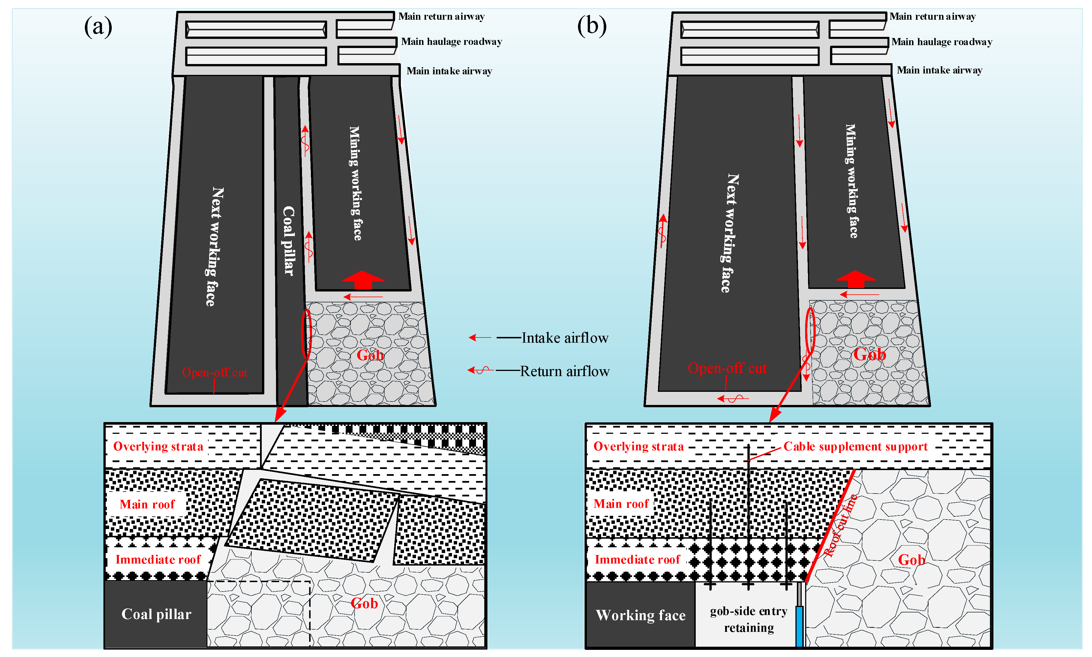
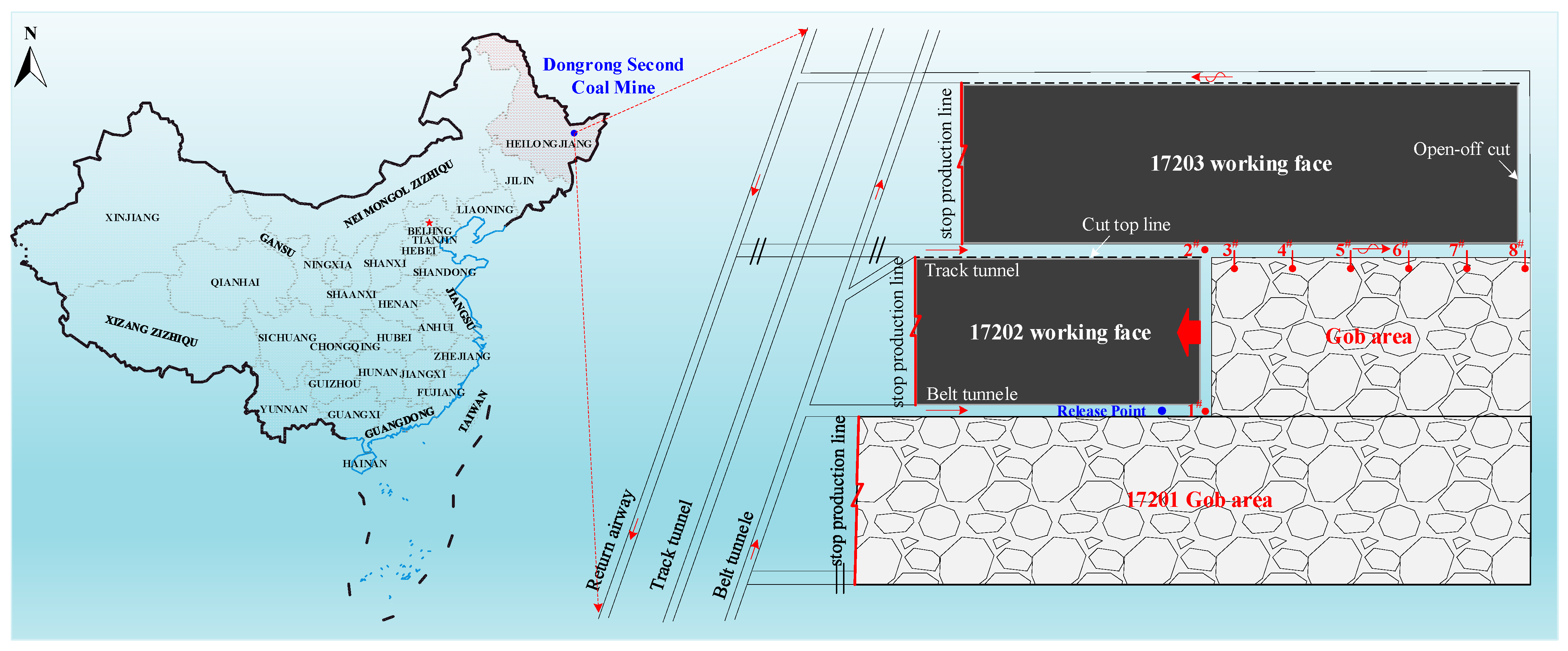
2. Engineering Background

The Dongrong Second Coal Mine is located in Heilongjiang Province, China. The 17202 working face is located in the No.17 coal seam of Dongrong Second Coal Mine. The working face applies the process of gob-side entry retaining by roof cutting and comprehensive mechanization longwall retreating coal mining method. The 17202 working plane measures 978 m in strike length and 180 m in tendency length and features an average coal seam thickness of 4.5 m. It also has a design mining height of 3.5 m and a coal seam inclination angle ranging from 19 to 21 degrees. This working face utilizes the “two-inlet-one return” Y-shaped ventilation system, where the belt lane serves as the main inlet with an airflow of 1680 m3/min. The track lane functions as the auxiliary inlet with an airflow of 530 m3/min, and the gob-side entry retaining by roof cutting serves as the return lane with an airflow of 2348 m3/min. The mine’s geographical location and the layout of the 17202 working plane are illustrated in Figure 2.

3. Methods and Simulation

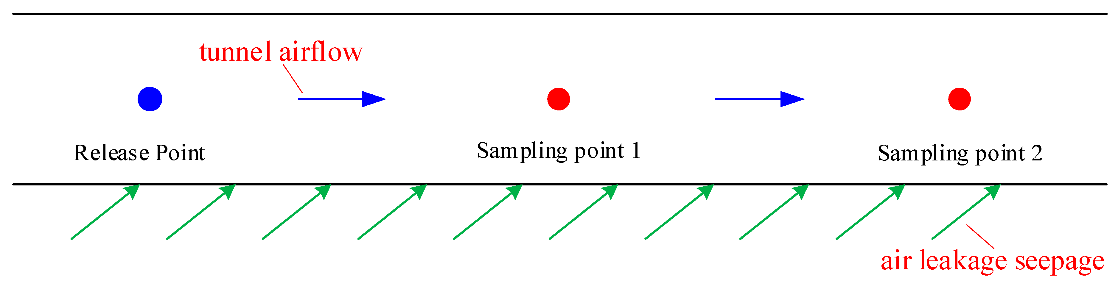
3.1. SF6 Tracer Gas Test Air Leakage

3.1.1. Air Leakage Tests in Goaf

The SF6 pulse release approach is utilized to measure the airflow migration pathway within the goaf of gob-side entry retaining through roof cutting and calculate the air leakage velocity.
The minimum air leakage speed within the goaf is calculated by the following formula [40]:
v min = L / t
where vmin is the minimum leakage wind speed, m/s; L is the linear distance from the tracer gas release point to the sampling point, m; t is the peak time from the tracer gas release to the detection of the tracer gas, s.
The formula for calculating the air leakage rate in the gob area is as follows:
k = m S F 6 inflow m S F 6 outflow m S F 6 inflow × 100 %
m S F 6 = V S F 6 ρ S F 6
V S F 6 = 0 t φ Q d t = v A 0 t φ d t
Q = v A
where k is the air leakage rate; m S F 6 is the mass of the tracer gas, kg; V S F 6 is the volume of the tracer gas, m3; ρ S F 6 is the density of the tracer gas, kg/m3; φ is the volume fraction of the tracer gas detected, 10−6; Q is the air volume, m3/s; v is the wind speed, m/s; A is the cross-sectional area of the tunnel, m2.
Following the current ventilation conditions in the mining working face, the release point of tracer gas is set 30 m from the inlet corner of the belt lane of the 17202 working face, sampling point 1# is set at the inlet corner of the belt lane of the 17202 working face, sampling point 2# is set at the junction of the railroad track lane and gob-side entry, sampling points 3#, 4#, 5#, 6#, 7#, and 8# are arranged at a depth of 0.5 m and a spacing of 55 m inside the gob-side entry retaining wall, as shown in the diagram in Figure 2. The SF6 tracer gas cylinder is connected to the pressure-reducing valve and flow meter, the release flow rate of the SF6 tracer gas is set to 109.49 L/min and is kept releasing for 30 min. From 0~5 min, each point is sampled every 1 min; from 5~30 min, each point is sampled every 5 min; from 30~180 min, each point is sampled every 10 min. A total of 200 gas samples are collected.

3.1.2. Air Leakage Tests in Gob-Side Entry Retaining Section

The continuous quantitative release method is employed to measure the extent of air leakage within the gob-side entry retaining section. The calculation method for continuous air leakage within the roadway is based on the estimated airflow migration route within the goaf of the 17202 working plane. The principle is to set sampling points 1# and 2# along the airflow direction in the roadway, and the tracer gas is continuously and quantitatively released at the release point. After the tracer gas reaches a stable state in the airflow in the roadway, the air volume of sampling point 1# is recorded as Q1, and the detected SF6 tracer gas concentration is recorded as C1. The air volume of the sampling point 2# is recorded as Q2, and the concentration of SF6 tracer gas is recorded as C2 [30], as shown in Figure 3.
Let the amount of SF6 gas released be q. Based on the law of conservation of mass, q = Q1·C1 = Q2·C2. If there is air leakage between two points, the amount of air leakage between the two points is ∆Q = Q2Q1. Therefore, we can obtain:
Δ Q = Q 2 Q 1 = q C 1 q C 2
The calculation formula for the air leakage rate of the laneway:
α i = C i + 1 C i C i × 100 %
Based on the continuous constant release SF6 flow formula:
q = K C Q × 10 6
where q is the SF6 tracer gas release, ml/min; K is the error coefficient, taken as 0.05; Q is the air volume of the lane; C is the minimum concentration of SF6 in the expected airflow, taken as 10−8.
To determine the amount of air leakage within the gob-side entry retaining section, the release point of SF6 tracer gas is established at measurement point 2# in Figure 2, while measurement points 3# to 8# are designated as the sampling points. The SF6 release volume is set to 1200 mL/min according to the preset SF6 tracer gas release flow rate. After 20 min of release, it is uniformly mixed with the airflow of the roadway to reach a stable state, and gas sampling is performed at each sampling detection point.

3.2. Air Leakage Law Simulation in the Gob

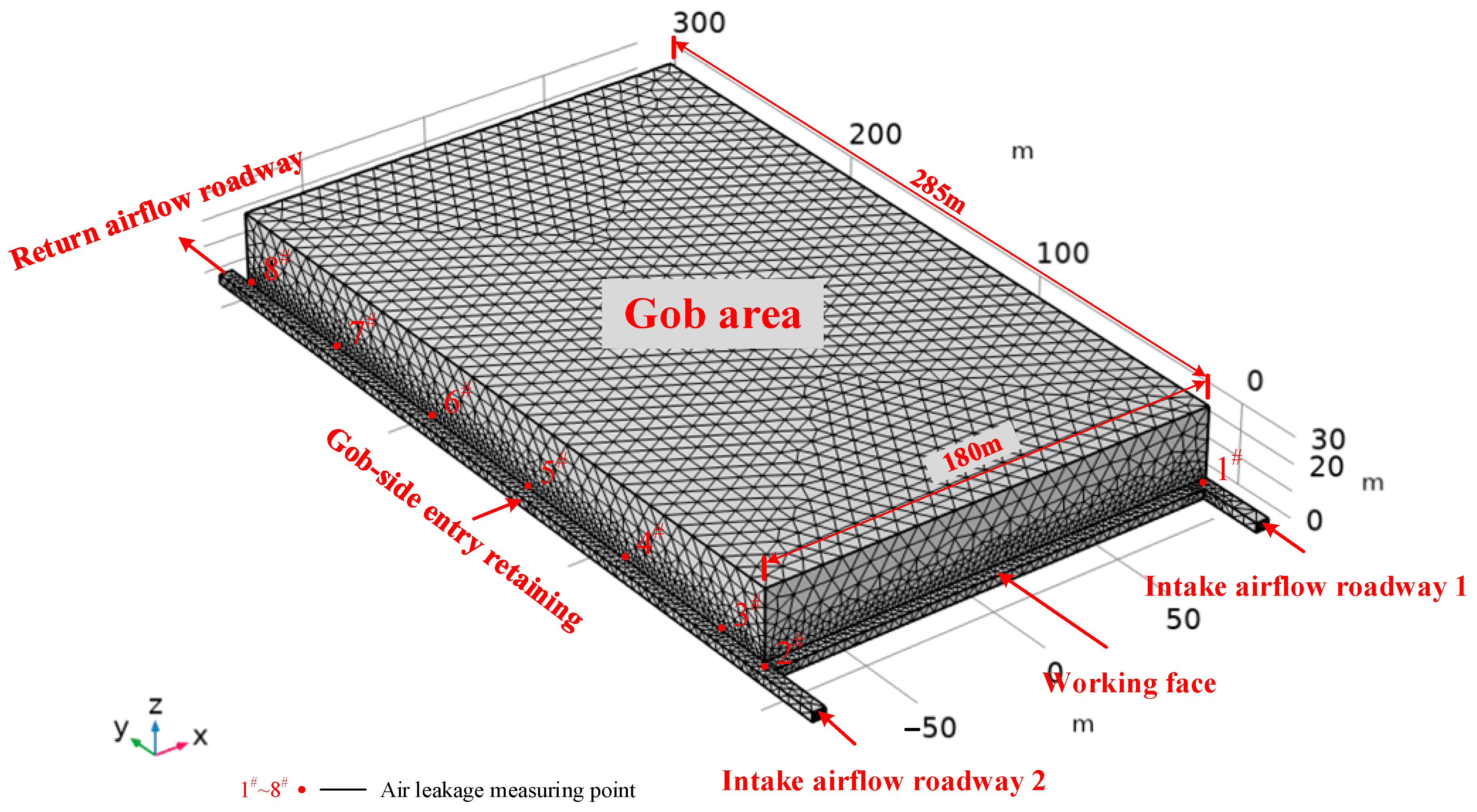
3.2.1. Geometric Model and Simulation Conditions

A three-dimensional physical model of the goaf under the Y-shaped ventilation pattern of “two intakes and one return” is established based on the real working conditions of the 17202 working plane, as illustrated in Figure 4. The goaf has a depth of 285 m, a working face tendency length of 180, a height of 30 m, and a floating coal thickness of 0.5 m, and the overlying strata in the goaf have a thickness of 29.5 m. To enhance calculation accuracy and decrease computation time, the model is segmented using free triangle and quadrilateral meshes. The area around the working plane and the gob-side entry retaining section is further refined, resulting in a total of 75,617 unit grids.
To facilitate modeling and calculation, the following assumptions are made: (1) no other chemical reactions are occurring in the stable internal flow field of the goaf; (2) the fragmented coal and rock material within the goaf forms an isotropic porous medium; (3) the gas in the whole flow field model is ideal incompressible gas; (4) there is no heat source in the goaf, and the model does not consider the energy equation. The temperature of the goaf, intake roadway, and return roadway is implanted to 298 K, the oxygen concentration of the working face in standard state is implanted to 21%, and the oxygen concentration of goaf is set to 0. The specific geometric dimensions, boundary conditions, and simulation parameters for the three-dimensional goaf physical model are displayed in Table 1.

3.2.2. Control Equations [27,40]

(1) Conservation of mass equation:
ρ t + ( ρ v ) = S m
where ρ is the density, kg/m3; t is the time, s; v is the velocity, m/s; Sm is the mass, kg/(m3∙s).
(2) Conservation of momentum equation:
ρ t ( ρ v ) + ( ρ v ) = p + ( τ ) + ρ g + F
where t is the time, s; p is the hydrostatic pressure, Pa; τ is the stress tensor, N/m2; ρg is the gravitational body force, N; F is the external body force, N.
(3) Ideal gas equation of state:
ρ = p M R T
where p is the pressure, Pa; M is the molar mass of the gas, g/mol; R is the ideal gas constant, 8.314 J/(mol·K); T is the temperature, K.
(4) Gas component transport equation:
t ( C i ) = ( D i C i ) ( u C i ) + R i
where Ci is the gas component inside the goaf, mol/m3; Di is the diffusion coefficient of the gas component, m2/s; Ri is the source (sink) terms of gas components, mol/(m3·s); u is the velocity field.

4. Results Analysis

4.1. Analysis of Air Leakage Using SF6 Tracer Gas Testing

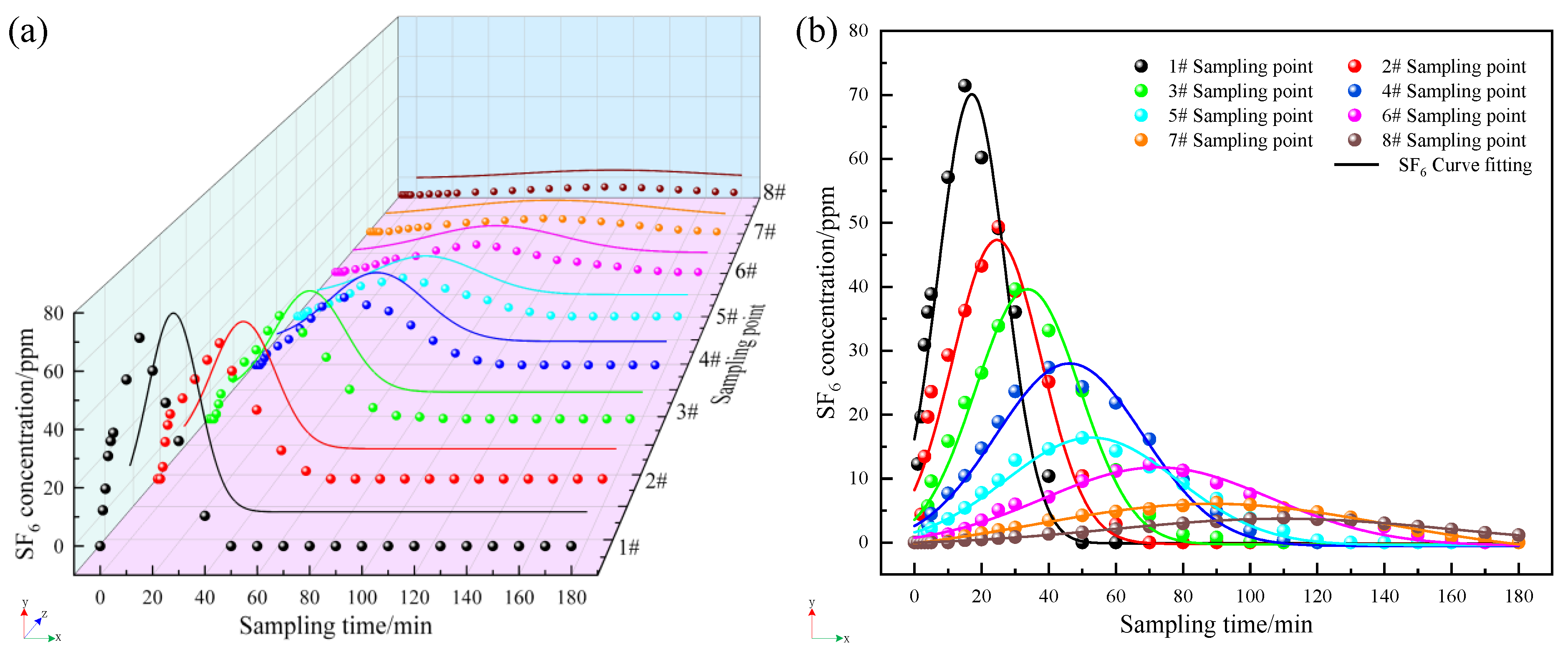
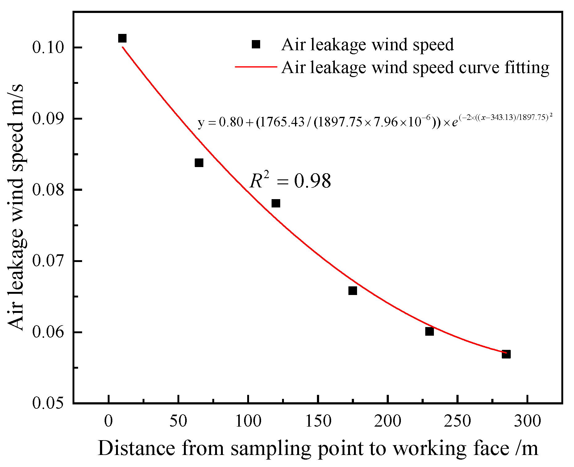
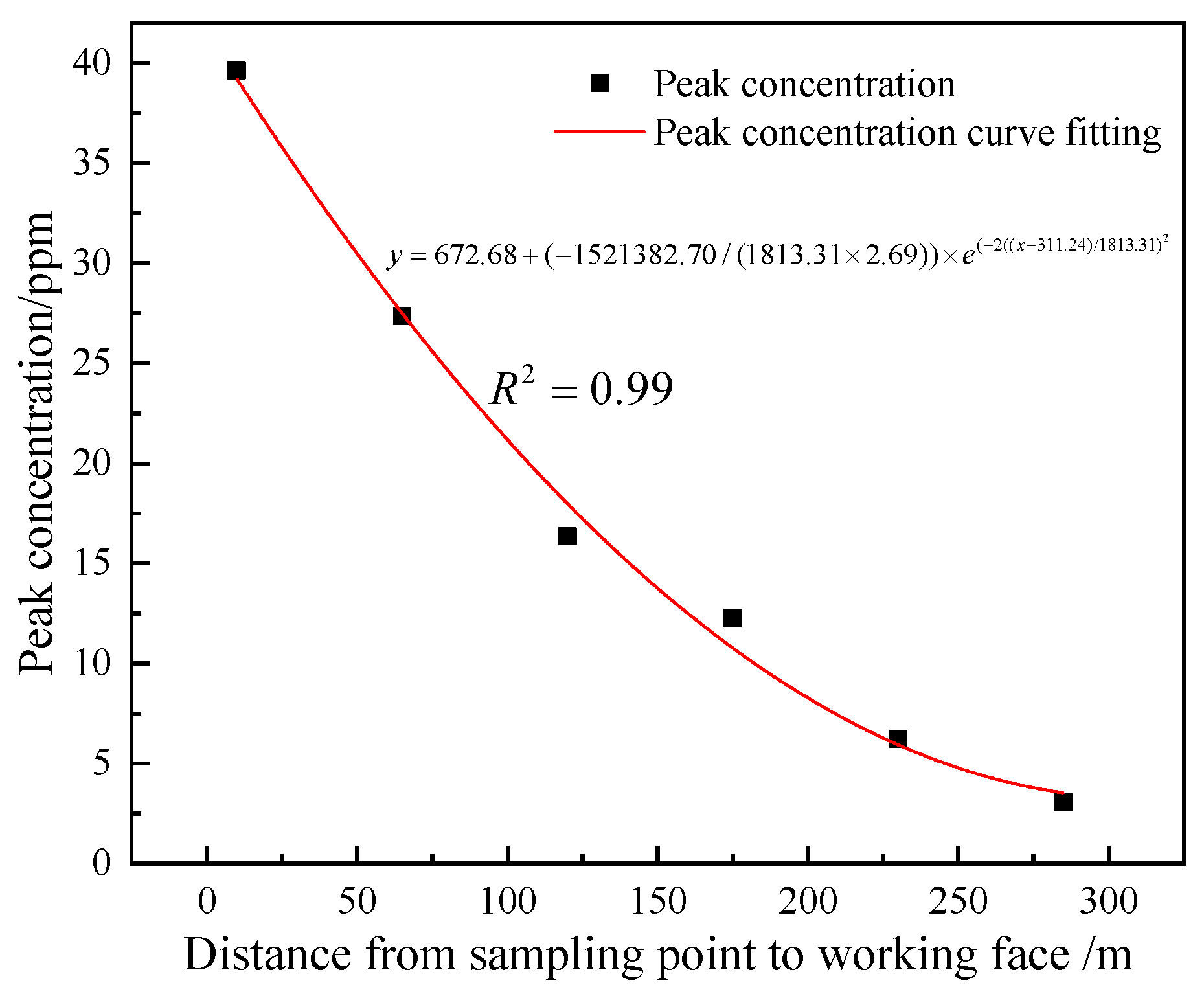
4.1.1. Air Leakage Characteristics in Goaf

The information presented in Figure 5 indicates that the SF6 tracer gas is released at the end of the sampling, and the whole detection process is 180 min. Among them, SF6 tracer gas is detected at point 1# closest to the release point for the first time, and SF6 concentration reaches a detection peak of 71.47 ppm at 15 min. The SF6 concentration of sampling point 2# reaches a detection peak of 49.38 ppm at 25 min. The SF6 concentration of sampling point 3# reaches a detection peak of 39.63 ppm at 30 min. The SF6 concentration of sampling point 4# reaches a detection peak of 27.36 ppm at 40 min. The SF6 concentration of sampling point 5# reaches a detection peak of 16.36 ppm at 50 min. The SF6 concentration of sampling point 6# reaches a detection peak of 12.27 ppm at 70 min. The SF6 concentration of sampling point 7# reaches a detection peak of 6.23 ppm at 90 min. The SF6 concentration of sampling point 8# reaches a detection peak of 3.87 ppm at 110 min. This shows that the farther the distance from the SF6 tracer gas release point, the longer the peak time of the detected SF6 concentration and the smaller the peak concentration.
According to the formula for calculating the minimum air leakage within the goaf and the formula for calculating the air leakage rate within the goaf, it is calculated that the minimum air leakage speeds of sampling points 3#~8# within the gob area of the 17202 working face are 0.1013 m/s, 0.0838 m/s, 0.0781 m/s, 0.0658 m/s, 0.0601 m/s, and 0.0569 m/s in order, and the leakage rate in the gob area is 20.07%. Data fitting is used to analyze the air leakage velocity and peak concentration at each sampling point, with the specific fitting results displayed in Figure 6 and Figure 7.
As can be seen from Figure 6 and Figure 7, with the depth in the buried depth of the goaf, the overlying rock activity inside the goaf tends to stabilize and the falling rock gradually compacts, which leads to a significant decrease in the leakage wind speed and peak concentration in goaf.
After conducting calculations, the approximate migration route of airflow in the goaf of 17202 working face is found. At first, the airflow from the primary main intake airflow roadway into the goaf seeps into the goaf region. Over time, the airflow escapes through the gob-side entry retaining wall.

4.1.2. Air Leakage Degree of Gob-Side Entry Retaining Section

After the SF6 tracer gas is released for 20 min and the roadway air flow is uniformly mixed to a stable state, a 5 L sampling airbag is used to sample three times at sampling points 3#~8# set up within the gob-side entry retaining, and the sampling time and position are marked on the surface of the airbag and sent to the laboratory for chromatographic analysis. Finally, the SF6 concentration at each sampling point is obtained by averaging. The findings are displayed in Table 2.
Data from the detection show that the distance between the SF6 sampling point and release point increases, and the concentration of the SF6 tracer gas decreases.
According to Equations (6) and (7), the air leakage volume and air leakage rate of the section of gob-side entry retaining and the findings are displayed in Table 3.
As can be seen from Table 3, the degree of air leakage in sections 3#~4# is extremely serious, with the air leakage amount reaching 103.91 m3/min. The air leakage rate is 5.38%, followed by the rest of the sections. As the waste material in the mined-out section becomes more compressed, the amount of air escaping from the mined-out area into the gob-side entry retaining gradually diminishes. In the 17202 working plane, the volume of air leakage total for the gob-side entry retaining section is 171.59 m3/min, representing 7.3% of its overall air volume.

4.2. Analysis of Simulation Results Regarding Air Leakage in the Goaf

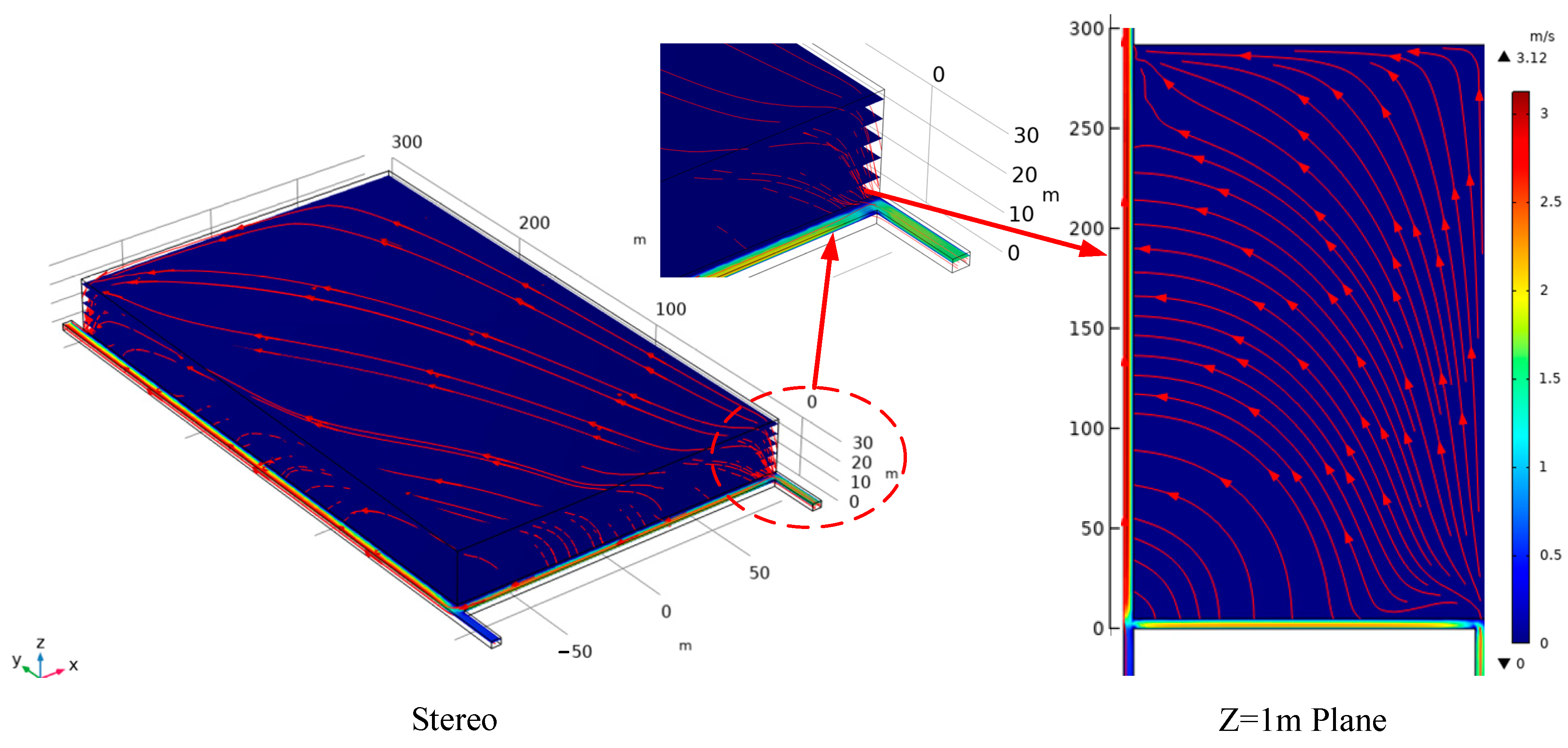
4.2.1. The Law of Airflow Migration in the Goaf

Simulation calculations are used to determine the airflow migration path and distribution of air leakage velocity within the goaf of the 17202 working plane, as depicted in Figure 8 and Figure 9. Additionally, Figure 10 compares the actual measurements of air leakage within the goaf, with the results obtained from numerical simulations.
As depicted in Figure 8, the airflow leaks into the goaf from the working plane and then seeps into the mined-out area. As it reaches a specific height, the airflow shifts horizontally towards the gob-side entry retaining side. Upon reaching the gob-side entry retaining area, the airflow descends to the lower part of the gob region and escapes from the gob-side entry retaining side. The airflow migration streamlines within the gob area of the 17202 working plane are shaped like an L when viewed on the z = 1 m plane. As airflow leaks from the working plane into the mined-out area and reaches a particular level, it is redirected approximately 90° towards the gob-side entry retaining wall and finally escapes from the gob-side entry retaining wall.
The larger air leakage wind speed within the goaf of the 17202 working plane can be observed in Figure 9, located at the corners on both sides of the working face. The significant air leakage area at the corner of the main air intake roadway is attributed to the high wind speed within the main intake airflow roadway, the low degree of roof collapse and compaction in the goaf, and the low-pressure zone on the side of the gob-side entry retaining wall. The large air leakage wind speed in the corner of the gob-side entry retaining is caused by the delay in the collapse of the wall and the loose roof connection, resulting in a direct connection between the gob-side entry retaining and the goaf.
The results from the numerical simulation in Figure 10 indicate that the air leakage within the goaf is slightly higher than what is observed in the field measurements. The reason is that the real measurement value is slightly lower than the numerical simulation value because of the impact of field conditions and sampling techniques, detection equipment, and other factors in the actual test process, which is in line with the actual situation within the allowable range of error. Therefore, the numerical simulation value is accurate and effective.

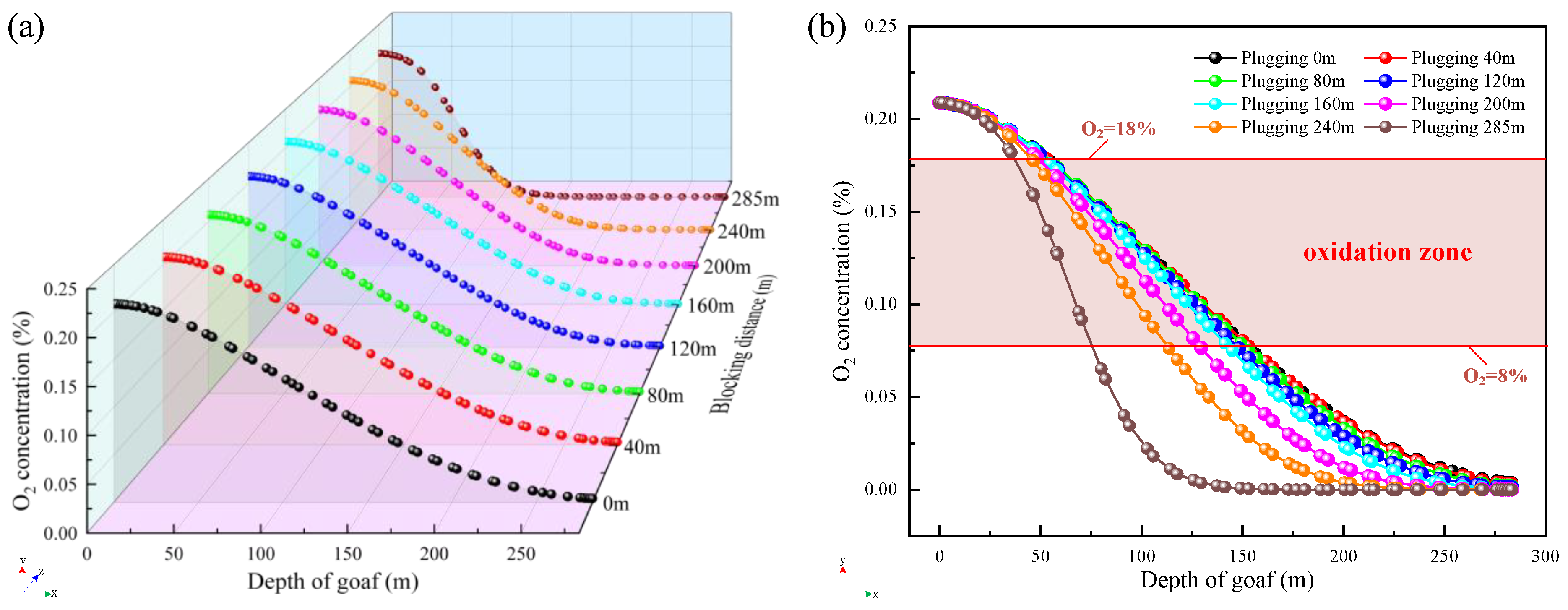
4.2.2. Oxygen Concentration Distribution Characteristics in Goaf

The result in Figure 11 shows a U-shaped distribution of three-dimensional oxygen concentration within the gob region of the 17202 working face. This pattern indicates that oxygen levels are high on the edges of the gob area and low in the center. The distribution of oxygen concentration within the mined-out area forms an L-shape at the z = 1 m plane. A spontaneous combustion zone emerges within a certain distance from the working plane, with a delineated banded spontaneous combustion zone visible alongside the gob area retaining roadway. The oxygen concentration index serves as the primary criterion for categorizing the “three zones” of CSC. These zones include the heat dissipation zone (oxygen concentration > 18%), the oxidation zone (18% ≤ oxygen concentration ≤ 8%), and the suffocation zone (oxygen concentration < 8%) in goaf areas. Based on this, the distribution scope of the heat dissipation zone, oxidation heating zone, and suffocation zone within the mined-out area for the 17202 working face is defined, as detailed in Table 4.

4.3. Analysis of Air Leakage Prevention in Goaf

The research findings above indicate a significant issue of air leakage within the gob-side entry retaining wall in the goaf. In this case, the peril of CSC within the goaf is high. Therefore, specific preventive measures must be implemented to avoid CSC within the mined-out area. In this regard, for the serious air leakage problem within the gob-side entry retaining wall in the goaf, an air leakage blocking technology is proposed (spraying and plugging the gob-side entry retaining wall in the goaf since the open-off cut of the working plane), and the flow field change rule of the goaf under the blocking distances of 40 m, 80 m, 120 m, 160 m, 200 m, 240 m, and 285 m is investigated; the placement of the spraying and plugging is presented in Figure 12.

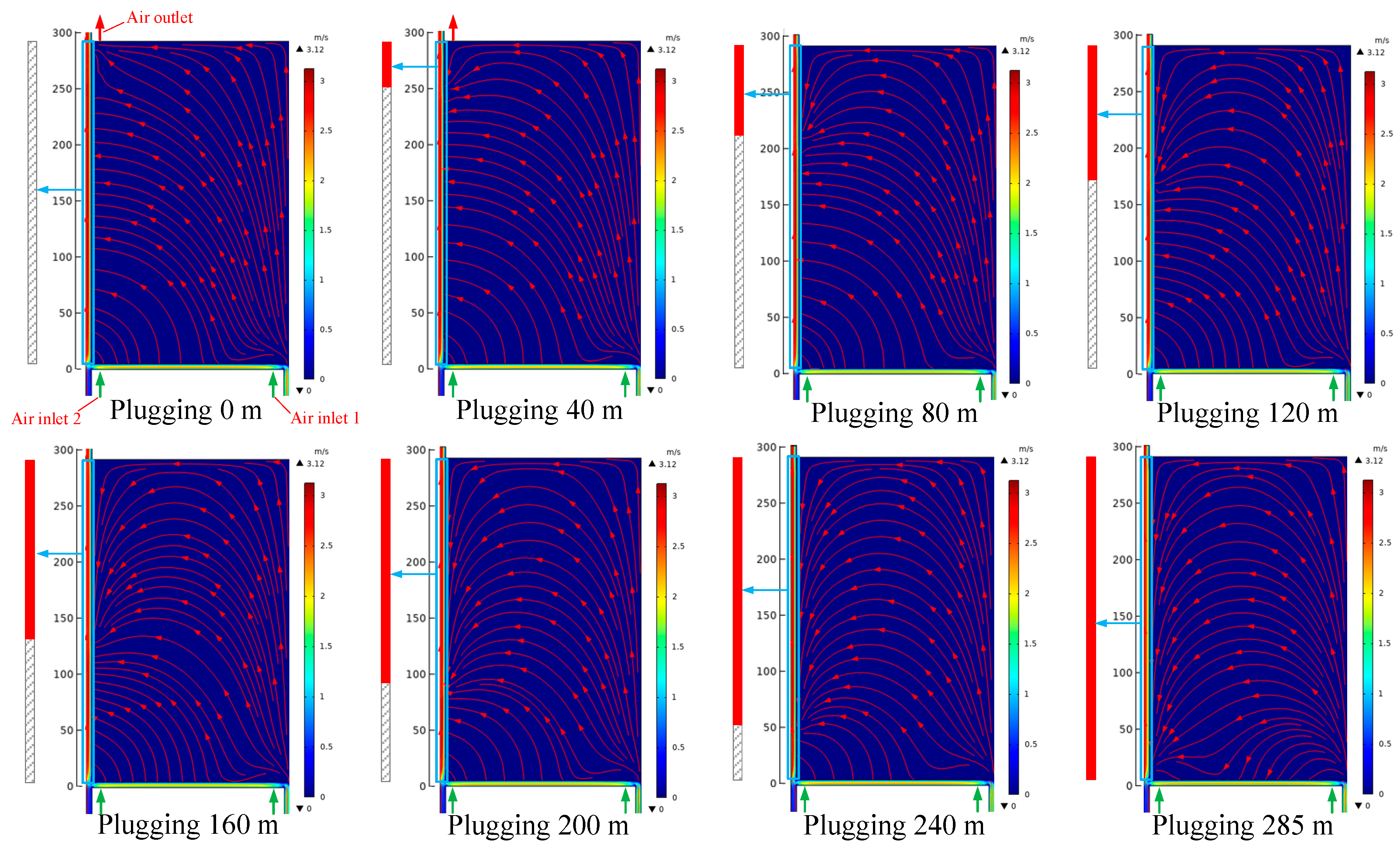
4.3.1. Characteristics of Flow Field Distribution in the Goaf

The graph in Figure 13 illustrates that, as the spraying distance on the side of gob-side entry retention increases, there is a noticeable shift in the airflow pattern from the working plane into the goaf, transitioning from an L-shaped distribution to a more distinct U-shaped distribution. Once the gob-side entry retaining wall is fully sealed off, the airflow flows into the mined-out area from the working plane on the side of the belt roadway. After a while, most of the airflow returns to the working plane on the side of the gob-side entry retaining. Only a small part of the airflow leaks into the goaf, which greatly reduces the air leakage within the mined-out area, thus reducing the risk of CSC within the goaf.

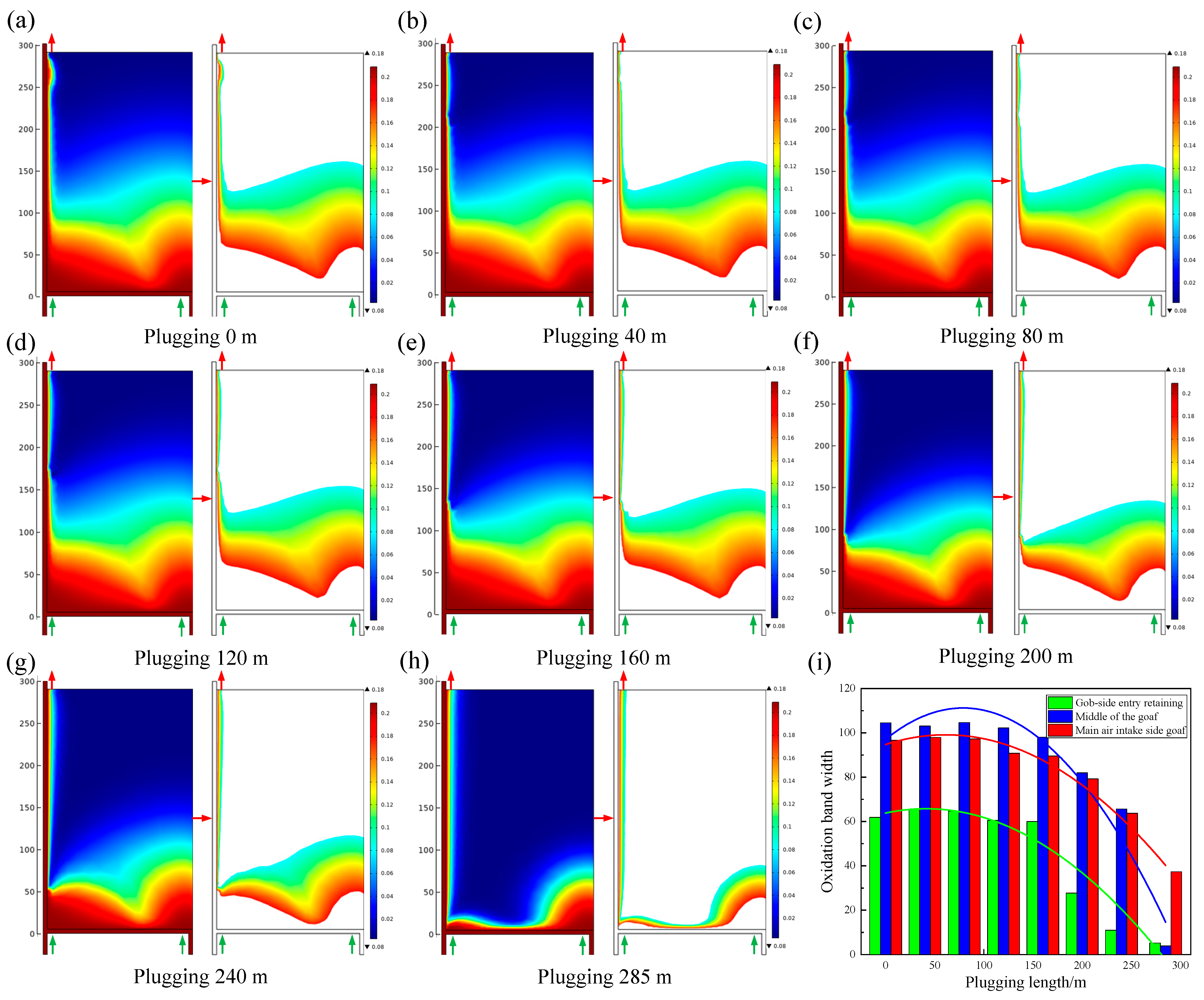
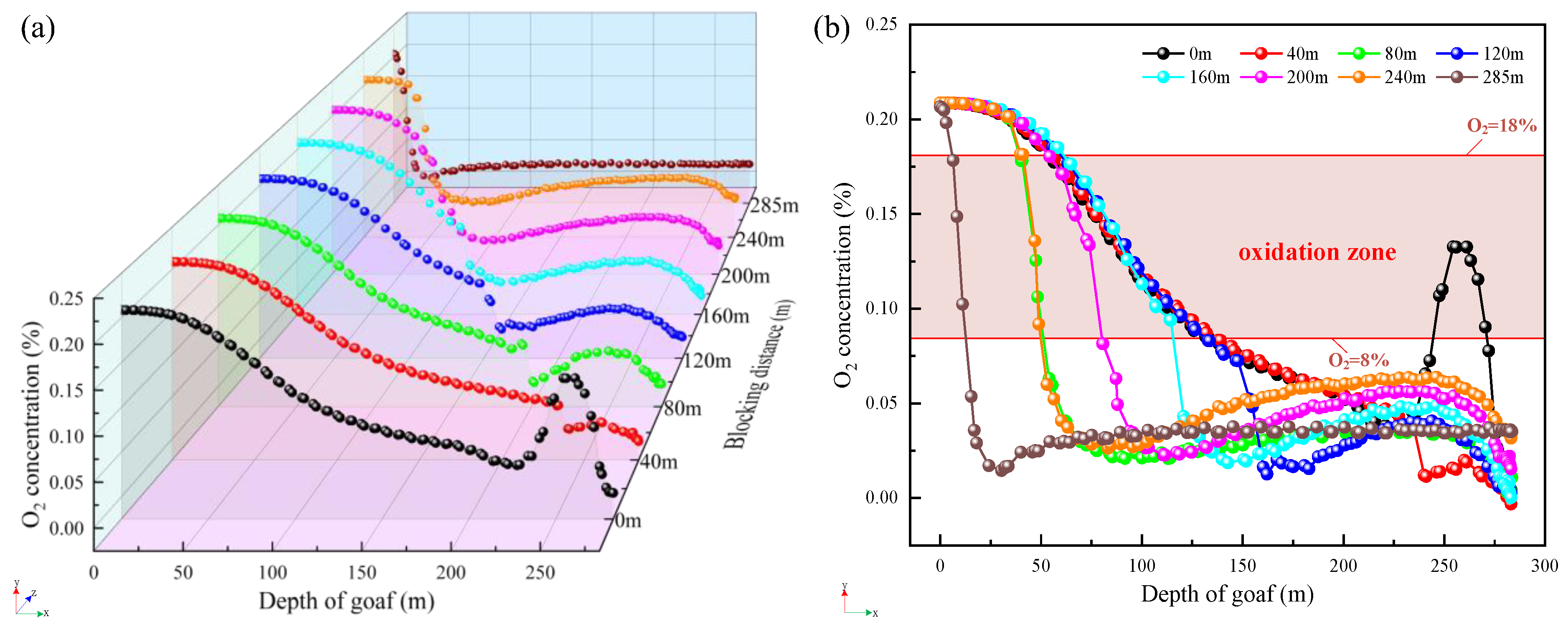
4.3.2. Characteristics of Oxygen Concentration Distribution in the Goaf

The results in Figure 14, Figure 15 and Figure 16 illustrate that addressing spraying and plugging leakage on the gob-side entry retaining wall can alter the extent of the oxidation zone distribution within the mined-out area. As the distance of spraying sealant increases, the spread of the oxidation zone within the goaf reduces. Once the spraying sealing distance extends to 285 m, the zone of oxidation within the gob area on the main air inlet side reduces from 58.7 m to 151.8 m to 42.8 m to 80.7 m, while the zone of oxidation in the middle of the gob area decreases from 63.8 m to 139 m to 6.8 m to 10.4 m. The oxidation zone in the mined-out area at the gob-side entry retaining walls decreases from 62.8 m~125.3 m to 13.3 m~20.1 m. It can be shown that spraying and sealing on the gob area side can effectively reduce the migration and diffusion range of oxygen within the gob area, decrease the extent of the oxidation zone distribution in the gob region, and decrease the likelihood of CSC in the gob area.

5. Applications

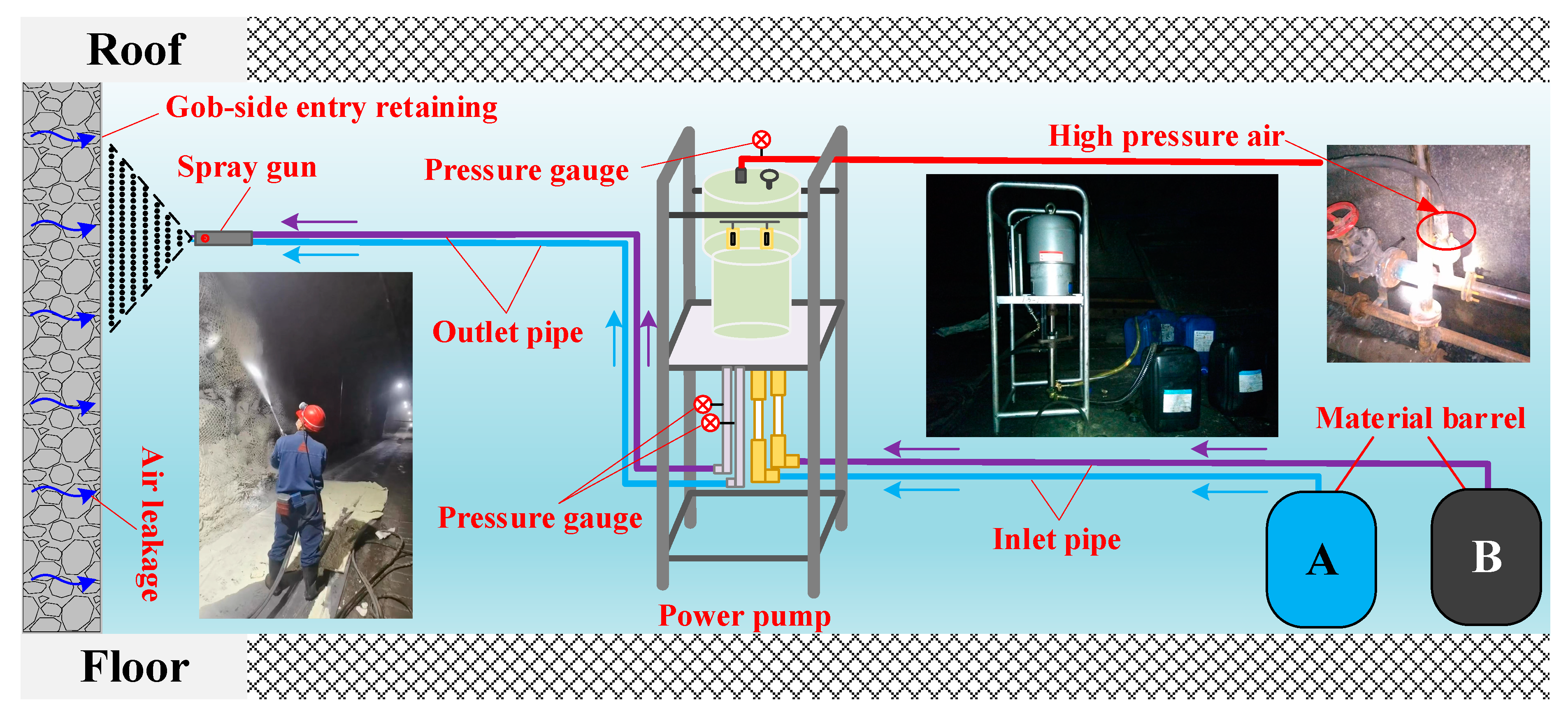
5.1. Plugging Construction

On the surface of a coal mine roadway, sprayed concrete or mortar is usually used to plug the air leakage, but, due to the lack of toughness of cement mortar after curing, the roadway is easily prone to cracks and falls away when it is deformed under pressure, thus losing the role of plugging the air leakage. To solve the problems existing in the process of plugging the roadway by traditional concrete spraying, after much market research, a two-component composite modified polyurethane roadway spraying and plugging material is found to be able to quickly and effectively seal the air leakage channels existing on the roadway surface of underground coal and rock bodies [41,42,43,44,45].
The material is tested according to the test method required by AQ 1116-2020 “General Safety Technical Specification for Polymer Materials for Reinforcement, Water Plugging, Filling and Spraying in Coal Mines” [46], and the measurement results are shown in Table 5.
According to the air leakage plugging effect of numerical simulation, stage spraying plugging measures are carried out on the gob-side entry retaining walls of the 17202 working face. Figure 17 depicts the on-site spraying construction process. The specific steps of the construction process are outlined below:
(1)
Substrate treatment. Use the pressurized air duct to flush the coal dust and dust on the surface of the roadway walls to ensure that the spray foam material is well-bonded to the roadway surface.
(2)
Worker protection. Use equipment such as gas masks and protective clothing to protect construction workers from injury.
(3)
Equipment connection. After connecting the air source, connect the two suction pipes to the A and B barrels, respectively. Pay special attention to the A cylinder for A material and the B cylinder for B material. Do not mix them.
(4)
Spraying construction. Spray with spray gun at a constant speed along the bottom of the roadway bottom plate from the bottom up to spray, the first spraying distance of about 5 mm or so, to be fully reactive material for the second surface spraying, for the unsprayed area or the need to strengthen the spraying position to make up the spray.
(5)
Cleaning. Immediately after stopping construction, wash with water to thoroughly clean the residual slurry.

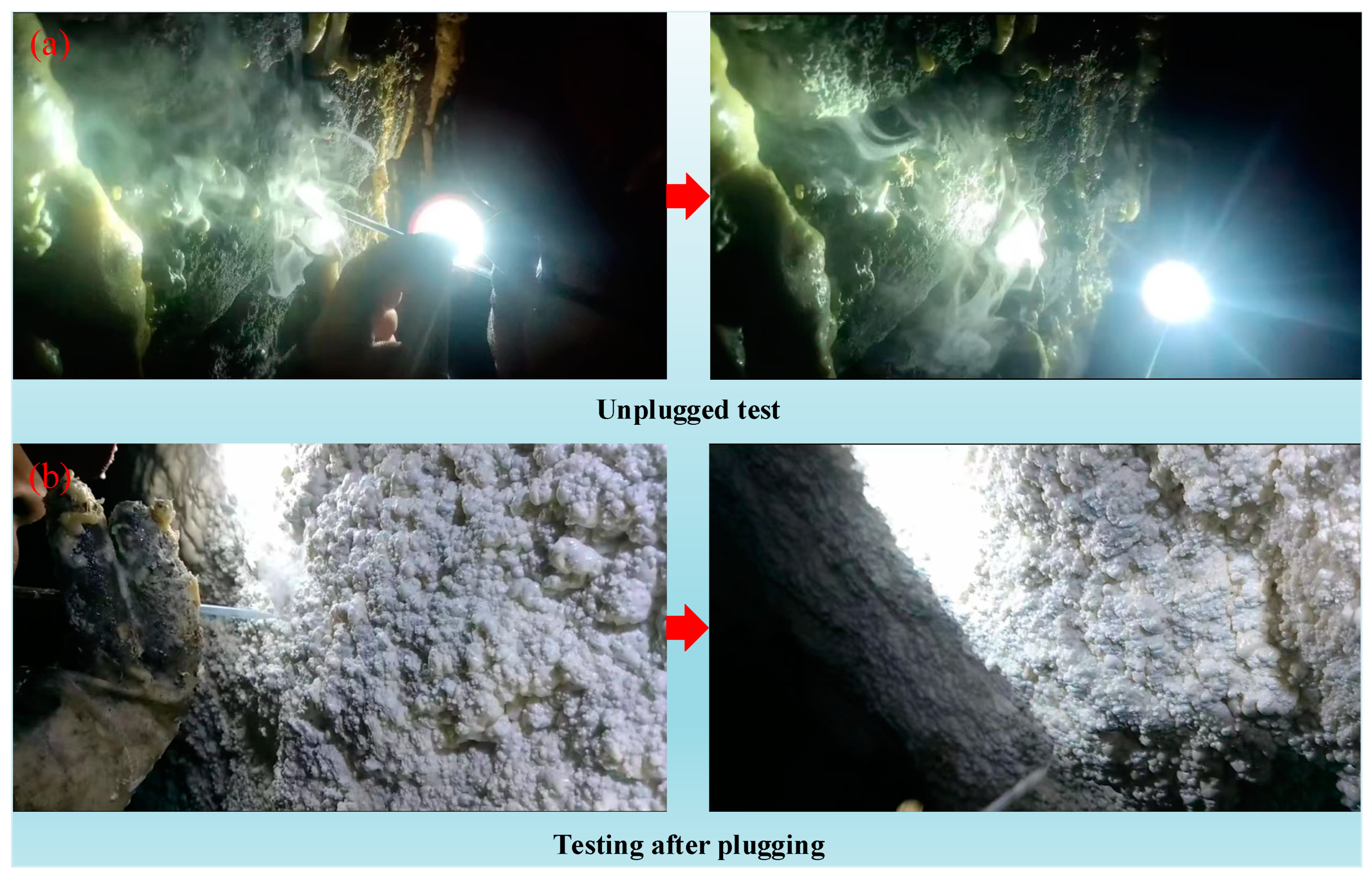
5.2. Effect Analysis

To evaluate the impact of air leakage on the gob-side entry retaining section, a smoke pipe is employed to examine the air leakage pathway before and after sealing. This process is illustrated in Figure 18.
As can be seen from Figure 16, if the gob-side entry retaining is not sprayed, smoke can be affected by air leaks from the gob area and will continue to spread outward vertically, eventually flowing out with the return airflow. After spraying, the smoke is barely affected by the air escaping from the gob area, and there is no obvious change in the vertical direction of the gob-side entry retaining wall. Therefore, it can be observed that, following the application of spraying and plugging techniques on the gob-side entry retaining wall, there is a clear reduction in the degree of air leakage from the gob area.
To conduct additional testing on the efficacy of spraying and plugging, SF6 tracer gas is employed to measure the extent of air leakage within the gob-side entry retaining section, with the outcomes presented in Table 6.
The test results show that the SF6 tracer gas concentration does not change much during the sampling period as the distance between the SF6 sampling point and the SF6 release point increases.
The volume of air leakage and the air leakage rate of the 17202 working plane following the application of gob-side entry retaining wall spraying and plugging are determined using Formulas (6) and (7). The specific calculations and results can be found in Table 7.
After testing, the degree of air leakage is relatively high in sections 3#~4#, with the air leakage amount reaching 12.24 m3/min and the air leakage rate being 0.68%, while there is no obvious air leakage in the rest of the sections. Evidently, with the gradual spraying and plugging of the gob-side entry retaining wall, the airflow leakage from the gob-side entry retaining section is dramatically reduced. The gob-side entry retention section of the 17202 working plane has an air leakage of 20.59 m3/min, which represents 0.87% of the total air volume in the gob-side entry retaining section.

6. Conclusions

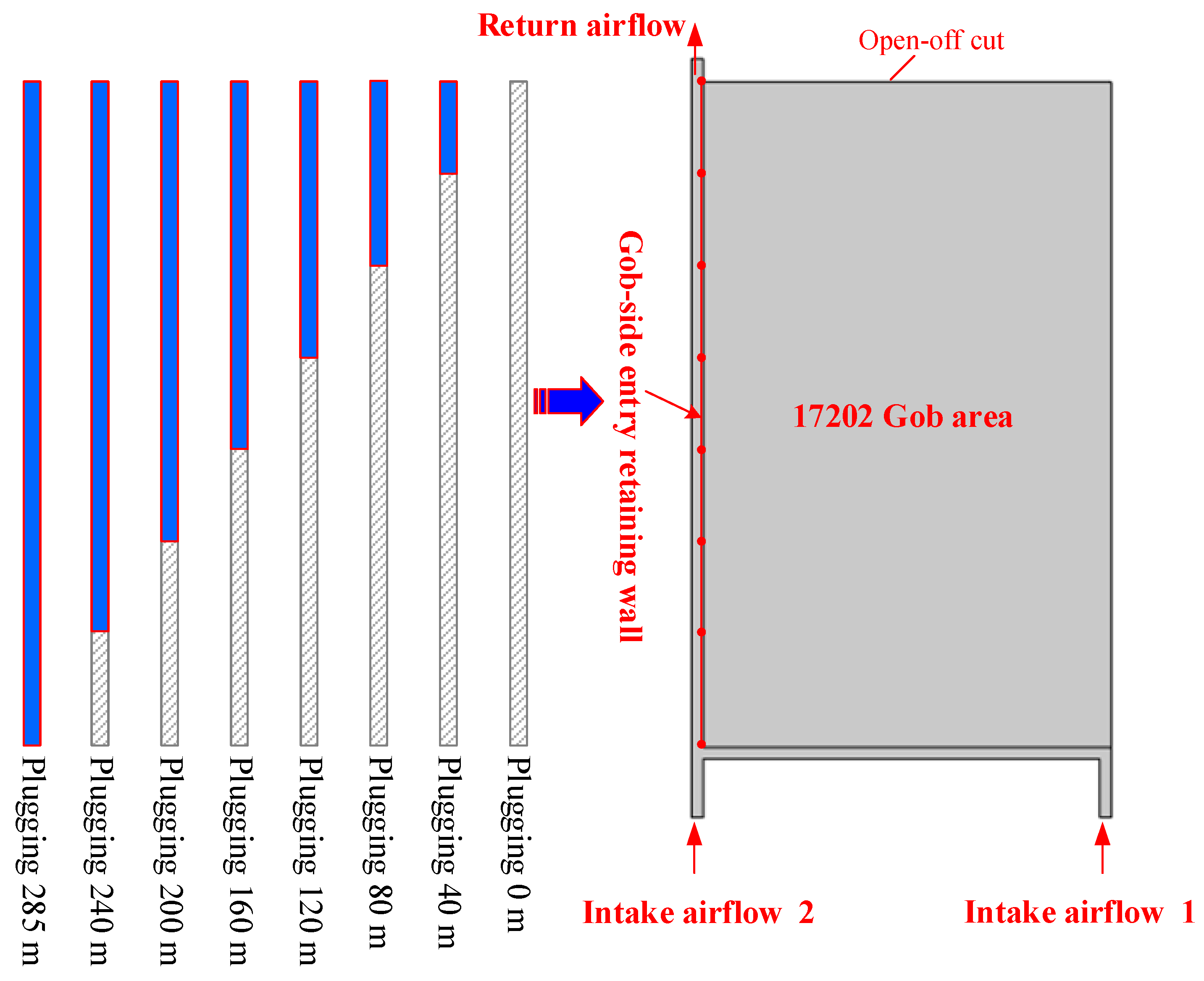
  • SF6 tracer gas is used to measure the approximate migration route of the airflow within the goaf of the 17202 working face, which flows into the working plane from the main air inlet lane and then leaks into the goaf, and, after a while, the airflow leaks out of the gap in the gob-side entry retaining wall. The total air leakage of the gob-side entry retaining section of the 17202 working face is 171.59 m3/min, representing 7.3% of the overall airflow within the gob-side entry retaining section.
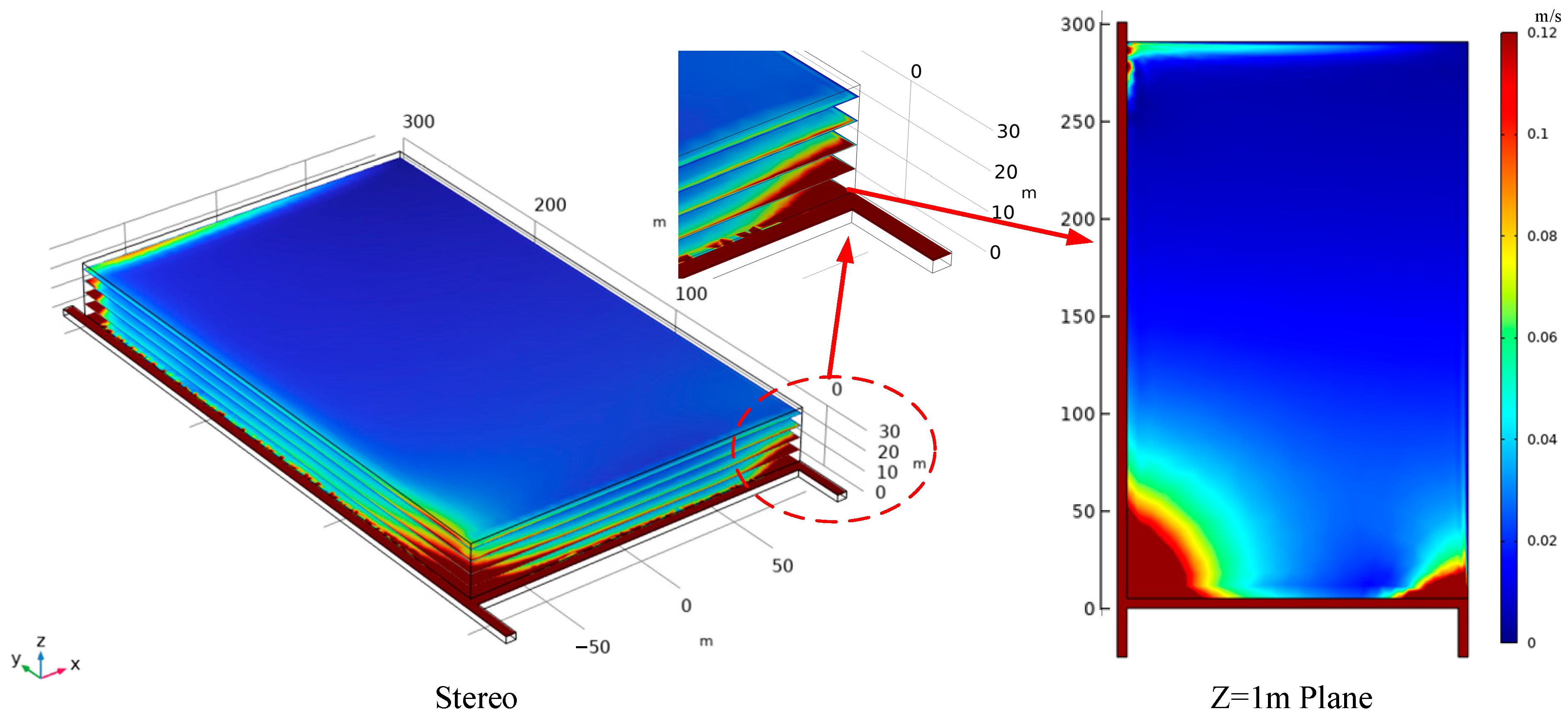
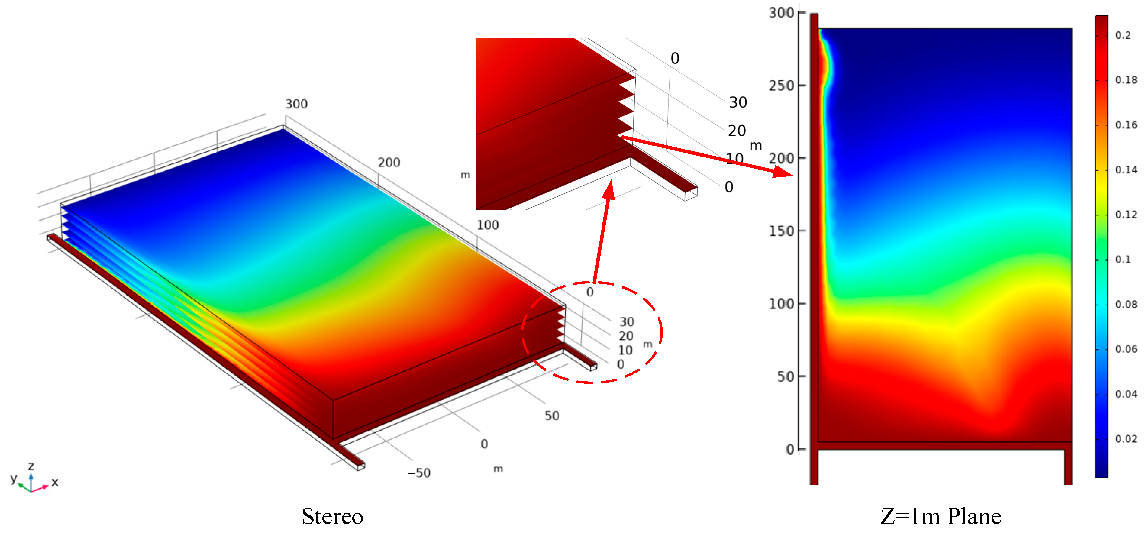
  • The simulation finds that the airflow from the working plane near the main intake airflow roadway leaks into the goaf and flows to its upper part, reaches a certain height, and then shifts horizontally to the gob-side entry retaining, and when the airflow is close to the gob-side entry retaining, it flows to the lower part of the zone and leaks out from the gob-side entry retaining wall. z = 1 plane, the air leakage route in the goaf shows an L-shape distribution, and the maximum width of the oxidation zone is 58.7 m~151.8 m. After the blocking measures are taken, the airflow migration route in the gob area becomes a U-shape distribution, and the maximum width of the oxidation zone reaches 42.8 m~80.7 m.
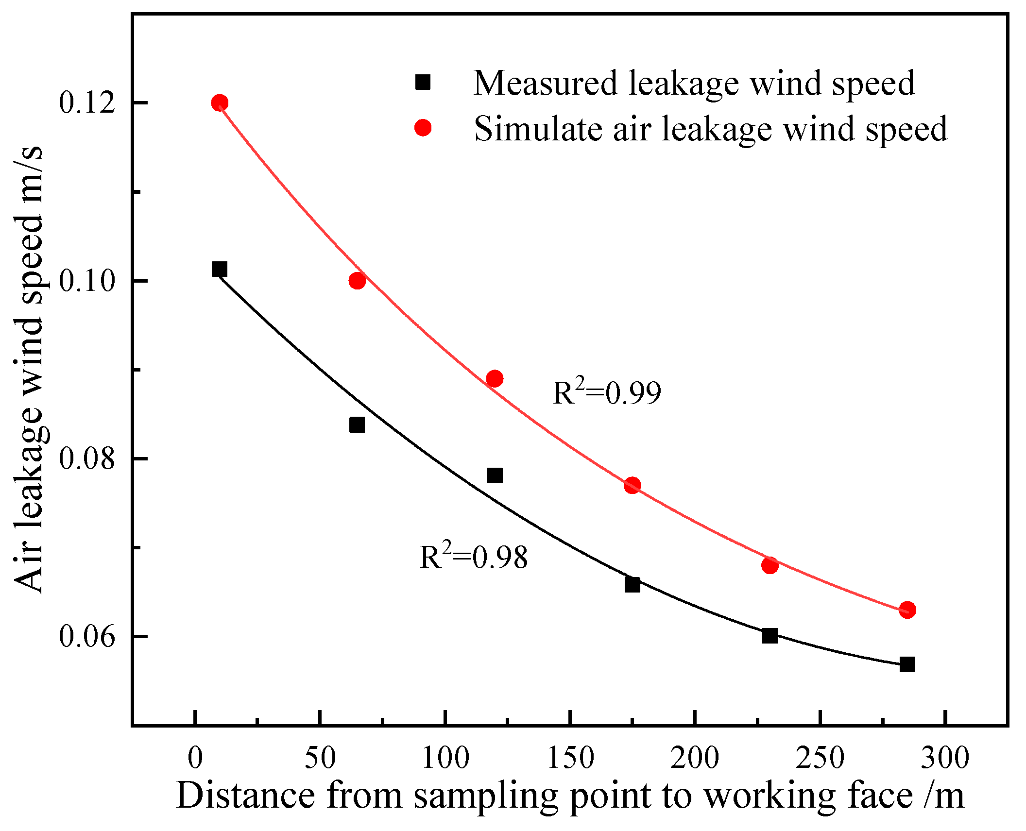
  • Following the application of sprayed material to seal the air leakage, the volume of air leakage within the gob-side entry retaining section decreases from 171.59 m3/min to 20.59 m3/min. This results in the overall air volume in the gob-side entry retaining section decreasing from 7.3% to 0.78%. It significantly minimizes air leakage in the gob area, decreases the risk of CSC within the gob area, and guarantees the safe operation of the mine.

Author Contributions

Z.Z.: Conceptualization, Methodology, and Writing—Original Draft Preparation; X.C.: Supervision and Writing—Review and Editing; Z.Y.: Supervision and Writing—Review and Editing; H.S.: Resources and Project Administration; D.H.: Investigation and Data Curation; J.W.: Investigation; H.Z.: Formal Analysis. All authors have read and agreed to the published version of the manuscript.

Funding

This research was funded by the National Natural Science Foundation of China (No. 51804245) and the Provincial Natural Science Foundation of Shaanxi (2022JQ-408).

Institutional Review Board Statement

Not applicable.

Informed Consent Statement

Not applicable.

Data Availability Statement

Data are contained within the article.

Conflicts of Interest

Author Hao Sun was employed by the company Heilongjiang Longmei Shuangyashan Mining Co., Ltd. The remaining authors declare that the research was conducted in the absence of any commercial or financial relationships that could be construed as a potential conflict of interest.

References

  1. Danish, E.; Onder, M. Application of Fuzzy Logic for Predicting of Mine Fire in Underground Coal Mine. Saf. Health Work 2020, 11, 322–334. [Google Scholar] [CrossRef]
  2. Kursunoglu, N.; Gogebakan, M. Prediction of spontaneous coal combustion tendency using multinomial logistic regression. Int. J. Occup. Saf. Ergon. 2022, 28, 2000–2009. [Google Scholar] [CrossRef] [PubMed]
  3. Ray, S.K.; Singh, R.P. Recent Developments and Practices to Control Fire in Underground Coal Mines. Fire Technol. 2007, 43, 285–300. [Google Scholar] [CrossRef]
  4. Deng, J.; Lei, C.; Xiao, Y.; Cao, K.; Ma, L.; Wang, W.; Laiwang, B. Determination and prediction on “three zones” of coal spontaneous combustion in a gob of fully mechanized caving face. Fuel 2018, 211, 458–470. [Google Scholar] [CrossRef]
  5. Ozcelik, M. Spontaneous combustion of coal seams in the Bengiler coal mine in Turkey. Euro-Mediterr. J. Environ. Integr. 2023, 8, 665–674. [Google Scholar] [CrossRef]
  6. Onifade, M. Countermeasures against coal spontaneous combustion: A review. Int. J. Coal Prep. Util. 2022, 42, 2953–2975. [Google Scholar] [CrossRef]
  7. Onifade, M.; Genc, B.; Gbadamosi, A.R.; Morgan, A.; Ngoepe, T. Influence of antioxidants on spontaneous combustion and coal properties. Process Saf. Environ. 2021, 148, 1019–1032. [Google Scholar] [CrossRef]
  8. Fernánez-Alaiz, F.; Castañón, A.M.; Gómez-Fernández, F.; Bernardo-Sánchez, A.; Bascompta, M. Analysis of the Fire Propagation in a Sublevel Coal Mine. Energies 2020, 13, 3754. [Google Scholar] [CrossRef]
  9. Bascetin, A.; Brune, J.F.; Adiguzel, D. The study of permeability changes of a gob structure in an underground coal mine to prevent spontaneous combustion. Int. J. Min. Reclam. Environ. 2021, 35, 693–708. [Google Scholar] [CrossRef]
  10. Tutak, M. Numerical research of oxidation zone variation in goaf of longwalls U-type system from borders and U-type system to the borders ventilated. IOP Conf. Ser. Earth Environ. Sci. 2019, 221, 012090. [Google Scholar] [CrossRef]
  11. Islavath, S.R.; Deb, D.; Kumar, H. Numerical analysis of a longwall mining cycle and development of a composite longwall index. Int. J. Rock Mech. Min. 2016, 89, 43–54. [Google Scholar] [CrossRef]
  12. Konicek, P.; Schreiber, J. Heavy rock bursts due to long-wall mining near protective pillars: A case study. Int. J. Min. Sci. Technol. 2018, 28, 799–805. [Google Scholar] [CrossRef]
  13. Sakhno, I.G.; Sakhno, S.V.; Kamenets, V.I. Stress environment around head entries with pillarless gob side entry retaining through numerical simulation incorporating the two type of filling wall. IOP Conf. Ser. Earth Environ. Sci. 2022, 1049, 012011. [Google Scholar] [CrossRef]
  14. Golubev, D.D. Using pillar-free mining technologies in gently dipping and self-ignitable coal seams. Min. Inf. Anal. Bull. 2020, 7, 64–77. [Google Scholar] [CrossRef]
  15. Tao, Z.; Song, Z.; He, M.; Meng, Z.; Pang, S. Principles of the roof cut short-arm beam mining method (110 method) and its mining-induced stress distribution. Int. J. Min. Sci. Technol. 2017, 28, 391–396. [Google Scholar] [CrossRef]
  16. Kim, B.; Walton, G.; Larson, M.K.; Berry, S. Experimental study on the confinement-dependent characteristics of a Utah coal considering the anisotropy by cleats. Int. J. Rock Mech. Min. 2018, 105, 182–191. [Google Scholar] [CrossRef] [PubMed]
  17. Wang, Y.; Wang, Q.; Tian, X.; Wang, H.; Yang, J.; He, M. Stress and deformation evolution characteristics of gob-side entry retained by roof cutting and pressure relief. Tunn. Undergr. Space Technol. 2022, 123, 104419. [Google Scholar] [CrossRef]
  18. Islavath, S.R.; Kasturi, P.K. Development of pillar extraction strategy for a coal panel and rib pillar stability index under the influence of the goaved-out panels. Arab. J. Geosci. 2023, 16, 13. [Google Scholar] [CrossRef]
  19. Singh, A.K.; Singh, R.; Maiti, J.; Kumar, R.; Mandal, P.K. Assessment of mining induced stress development over coal pillars during depillaring. Int. J. Rock Mech. Min. 2011, 48, 805–818. [Google Scholar] [CrossRef]
  20. Yadav, A.; Behera, B.; Sahoo, S.K.; Singh, G.S.P.; Sharma, S.K. An Approach for Numerical Modeling of Gob Compaction Process in Longwall Mining. Min. Metall. Explor. 2020, 37, 631–649. [Google Scholar] [CrossRef]
  21. Zhou, X.; Jing, Z.; Li, Y. Research on controlling gas overrun in a working face based on gob-side entry retaining by utilizing ventilation type “Y”. Sci. Rep. 2023, 13, 9199. [Google Scholar] [CrossRef] [PubMed]
  22. Arasteh, H.; Saeedi, G.; Farsangi, M.A.E.; Esmaeili, K. A New Model for Calculation of the Plastic Compression Index and Porosity and Permeability of Gob Materials in Longwall Mining. Geotech. Geol. Eng. 2020, 38, 6407–6420. [Google Scholar] [CrossRef]
  23. Janus, J. Numerical Investigation of Air Flow in Goaf While Mapping Its Flow Parameters. Processes 2023, 11, 987. [Google Scholar] [CrossRef]
  24. Tutak, M.; Brodny, J.; Szurgacz, D.; Sobik, L.; Zhironkin, S. The Impact of the Ventilation System on the Methane Release Hazard and Spontaneous Combustion of Coal in the Area of Exploitation—A Case Study. Energies 2020, 13, 4891. [Google Scholar] [CrossRef]
  25. Marzły, M.; Trzaskalik, P. Comparative Analysis of Methane Concentration Near the Junction of the Longwall and Top Road. Mang. Syst. Prod. Eng. 2019, 27, 166–173. [Google Scholar]
  26. Szlązak, N.; Obracaj, D.; Swolkień, J. Enhancing Safety in the Polish High-Methane Coal Mines: An Overview. Min. Metall. Explor. 2020, 37, 567–579. [Google Scholar] [CrossRef]
  27. Brodny, J.; Tutak, M. The Impact of the Strength of Roof Rocks on the Extent of the Zone with a High Risk of Spontaneous Coal Combustion for Fully Powered Longwalls Ventilated with the Y-Type System—A Case Study. Appl. Sci. 2019, 9, 5315. [Google Scholar]
  28. Roghanchi, P.; Kocsis, K.; Sunkpal, M. Sensitivity analysis of the effect of airflow velocity on the thermal comfort in underground mines. J. Sustain. Min. 2016, 15, 175–180. [Google Scholar] [CrossRef]
  29. Rezaei, M. Long-term stability analysis of goaf area in longwall mining using minimum potential energy theory. J. Min. Environ. 2018, 9, 169–182. [Google Scholar]
  30. Miao, D.; Chen, X.; Ji, J.; Lv, Y.; Zhang, Y.; Sui, X. New Technology for Preventing and Controlling Air Leakage in Goaf Based on the Theory of Airflow Boundary Layer. Processes 2022, 10, 954. [Google Scholar] [CrossRef]
  31. Saki, S.A.; Brune, J.F.; Khan, M.U. Optimization of gob ventilation boreholes design in longwall mining. Int. J. Min. Sci. Technol. 2020, 30, 811–817. [Google Scholar] [CrossRef]
  32. Khattri, S.K.; Log, T.; Kraaijeveld, A. Tunnel Fire Dynamics as a Function of Longitudinal Ventilation Air Oxygen Content. Sustainability 2019, 11, 203. [Google Scholar] [CrossRef]
  33. Kurnia, J.; Sasmito, A.; Mujumdar, A. Simulation of a novel intermittent ventilation system for underground mines. Tunn. Undergr. Space Technol. 2014, 42, 206–215. [Google Scholar] [CrossRef]
  34. Menéndez, J.; Merlé, N.; Fernández-Oro, J.M.; Galdo, M.; de Prado, L.Á.; Loredo, J.; Bernardo-Sánchez, A. Concentration, Propagation and Dilution of Toxic Gases in Underground Excavations under Different Ventilation Modes. Int. J. Environ. Res. Public Health 2022, 19, 7092. [Google Scholar] [CrossRef] [PubMed]
  35. Vives, J.; Bascompta, M.; Felipe, J.J.; Sanmiquel, L. Computational Fluid Dynamics (CFD) study to optimize the auxiliary ventilation system in an underground mine. Dyna 2022, 89, 84–91. [Google Scholar] [CrossRef]
  36. Tian, Y.; Yang, C.; Sun, Q.; Chang, K.; Guo, Z. Air leakage law in goaf of the working face using U-type ventilation. Coal Eng. 2020, 52, 132–136. [Google Scholar]
  37. Zhai, X.; Wang, B.; Jiang, S.; Zhang, W. Oxygen Distribution and Air Leakage Law in Gob of Working Face of U+L Ventilation System. Math. Probl. Eng. 2019, 2019, 8356701. [Google Scholar] [CrossRef]
  38. Li, T.; Wu, B.; Lei, B.; Huang, Q. Study on air leakage and gas distribution in goaf of y-type ventilation system. Energy Source Part A 2020, 5, 1–14. [Google Scholar] [CrossRef]
  39. Guo, L.; Yao, J.; Su, X. Influence of W-type and U-type ventilation methods on working face. IOP Conf. Ser. Earth Environ. Sci. 2020, 546, 042014. [Google Scholar] [CrossRef]
  40. Zhu, X.; Wen, H. Numerical simulation study on the influence of air leakage on oxygen concentration in goafs of fully mechanized caving mining with shallow buried and large mining height. Front. Earth Sci. 2023, 11, 1138925. [Google Scholar] [CrossRef]
  41. Zhang, F.; Liu, W.; Qin, Y.; Chu, X.; Xu, H.; Wu, F.; Li, Y. Optimization of coalbed methane recovery from extraction borehole using novel plastic spraying material: A field application and evaluation. Process Saf. Environ. 2022, 169, 534–546. [Google Scholar] [CrossRef]
  42. Biswal, P.K.; Parida, D.; Mishra, G.; Sahoo, A.K. Study of air flow pattern in mine model gallery and its validation using CFD modelling. World Sci. News 2019, 130, 1–24. [Google Scholar]
  43. Krukovskyi, O.; Kurnosov, S.; Makeiev, S.; Ryzhov, H.; Pilipenko, Y. Tamponage of massif by modern polymeric materials for isolating mined-out areas in the coal seams prone to spontaneous ignition. IOP Conf. Ser. Earth Environ. Sci. 2022, 970, 012046. [Google Scholar] [CrossRef]
  44. Zhang, Y.; Zou, Q.; Guo, L. Air-leakage Model and Sealing Technique with Sealing–Isolation Integration for Gas-drainage Boreholes in Coal Mines. Process Saf. Environ. 2020, 140, 258–272. [Google Scholar] [CrossRef]
  45. Xi, X.; Jiang, S.; Yin, C.; Wu, Z. Experimental investigation on cement-based foam developed to prevent spontaneous combustion of coal by plugging air leakage. Fuel 2021, 301, 121091. [Google Scholar] [CrossRef]
  46. AQ 1116-2020; General Safety Specification of Polymer Material for Consolidation, Water Stopping, Void Filling and Sprayed Sealing at Coal Mine. Ministry of Emergency Management of the People’s Republic of China: Beijing, China, 2020.
Figure 1. Process of the “121 mining method” and the “110 mining method”. (a) The 121 mining method. (b) The 110 mining method.
Fire 07 00098 g001
Figure 2. Schematic diagram of the geographic location of the mine and the layout of the working face.
Fire 07 00098 g002
Figure 3. Leakage into the detection space detection schematic.
Fire 07 00098 g003
Figure 4. Geometric model and grid generation.
Fire 07 00098 g004
Figure 5. Prediction time history of SF6 at each sampling point. (a) Three-dimensional perspective. (b) Two-dimensional perspective.
Fire 07 00098 g005
Figure 6. Prediction curve between leakage wind speed and working face distance.
Fire 07 00098 g006
Figure 7. Prediction curve between peak concentration and working face distance.
Fire 07 00098 g007
Figure 8. Prediction of airflow migration route in goaf.
Fire 07 00098 g008
Figure 9. Diagram of the distribution of air leakage velocity within the goaf area.
Fire 07 00098 g009
Figure 10. Comparison involving the measurable air leakage velocity within the goaf with the results obtained from numerical simulations.
Fire 07 00098 g010
Figure 11. Forecasting the distribution of oxygen concentration in the goaf.
Fire 07 00098 g011
Figure 12. Schematic diagram of phased plugging of air leakage.
Fire 07 00098 g012
Figure 13. Prediction of airflow migration route in the goaf during staged plugging process.
Fire 07 00098 g013
Figure 14. Prediction of oxygen concentration distribution in the goaf during staged plugging process. (a) plugging 0 m. (b) plugging 40 m. (c) plugging 80 m. (d) plugging 120 m. (e) plugging 160 m. (f) plugging 200 m. (g) plugging 240 m. (h) plugging 285 m. (i) The distribution of oxidation zone in goaf under different plugging distance.
Fire 07 00098 g014
Figure 15. Changes of oxygen concentration within the goaf of the main air inlet side under different plugging distances. (a) Three-dimensional perspective. (b) Two-dimensional perspective.
Fire 07 00098 g015
Figure 16. Changes of oxygen concentration in the goaf of gob-side entry retaining side under different plugging distances. (a) Three-dimensional perspective. (b) Two-dimensional perspective.
Fire 07 00098 g016
Figure 17. Spraying construction process of gob-side entry retaining wall.
Fire 07 00098 g017
Figure 18. Changes in smoke migration before and after plugging air leakage. (a) Unplugged test. (b) Test after plugging.
Fire 07 00098 g018
Table 1. Geometric size and simulation conditions of the simulation model.
CategoryParameterValue or Condition
Geometric sizeWorking face: x(m) × y(m) × z(m)180 × 5 × 3
Gob area: x(m) × y(m) × z(m)180 × 285 × 30
Intake airflow roadway 1: x(m) × y(m) × z(m)5 × 25 × 3
Intake airflow roadway 2: x(m) × y(m) × z(m)5 × 25 × 3
Return airflow roadway: x(m) × y(m) × z(m)5 × 300 × 3
Boundary conditions and simulation parametersInlet velocity 1: wind speed of belt roadway (m/s)1.6
Inlet velocity 2: wind speed in track lanes (m/s)0.5
OutletOutflow, p = 0
Gob’s internal statePorous zone
Other wallsZero slip
Porosity of porous media in goafUser-defined function
Thermal conductivity of coal (W·m−1·K−1)0.2
Porosity of floating coal0.3
Air diffusion coefficient (m2·s−1)1.5 × 10⁻⁵
Activation energy (J·mol−1)5 × 10⁴
Pre-exponential factor (s−1)180
Gas constant (J·mol−1·K−1)8.314
Oxygen consumption rate A C n e ( E a / RT ) [ ( 1 - q ) q ]
Note: A is the pre-exponential factor; C is the oxygen concentration; Ea is the activation energy; R is a gas constant; T is the temperature of the coal sample; q is the porosity of floating coal.
Table 2. Measurement results of air leakage volume within gob-side entry retaining section.
Release PointSampling PointsRelease Amount (mL/min)Detection Concentration (ppm)
The intersection of the 17202 working face and the gob-side entry retaining wall3#120062.21
4#59.03
5#58.11
6#57.54
7#57.23
8#57.12
Table 3. Measurement results of air leakage volume and air leakage rate of unsealed gob-side entry retaining wall.
Measurement SectionAir Leakage Volume
(m3/min)
Air Leakage Rate
(%)
Total Air Leakage Volume
(m3/min)
3#~4#103.915.38171.59
4#~5#32.191.58
5#~5#20.150.99
6#~7#11.300.54
7#~8#4.040.19
Table 4. 17202 working face gob area spontaneous combustion “three zones” distribution range.
Location within the GoafHeat Dissipation ZoneOxidation ZoneSuffocation Zone
Main air inlet tunnel side 0~58.7 m58.7 m~151.8 m>151.8 m
Middle0~36.8 m63.8 m~139 m>139 m
Gob-side entry retaining side0~62.6 m62.6 m~125.3 m>125.3 m
Table 5. Performance test results of two-component composite modified polyurethane spray plugging materials.
Serial NumberInspection ItemsTechnical SpecificationsTest Results
1Maximum reaction temperature,°C≤14094.7
2Expansion multiplier≥2531
3Stability (70 °C ± 2 °C, 48 h), %≤0.10.03
4Compressive strengthPressure strain 10%, kPa≥1065
Pressure strain 30%, kPa≥1026
Pressure strain 70%, kPa≥4043
5Oxygen index, %≥2828.3
6Air permeability, m2≤0.05≤0.005
7Flame retardant performanceAlcohol torch burning testFlame burning time, s≤30.3
Flameless burning time, s≤101.8
Flame extension length, mm≤280110
Alcohol lamp burning testFlame burning time, s≤60.3
Flameless burning time, s≤202.2
Flame extension length, mm≤25083
8Surface resistance, Ω≤3 × 1085.6 × 107
Table 6. Measurement of air leakage and analysis of SF6 concentration after plugging the remaining lane section.
Release PointSampling PointsRelease Amount (mL/min)Detection Concentration (ppm)
The intersection between the 17202 working face and the gob-side entry retaining wall3#120067.38
4#66.92
5#66.77
6#66.68
7#66.63
8#66.61
Table 7. Determination yields the air leakage results and the air leakage rate for the gob-side entry retaining after plugging.
Measurement SectionAir Leakage Volume
(m3/min)
Air Leakage Rate
(%)
Total Air Leakage Volume
(m3/min)
3#~4#12.240.6820.59
4#~5#4.030.22
5#~6#2.430.13
6#~7#1.350.07
7#~8#0.540.03
Disclaimer/Publisher’s Note: The statements, opinions and data contained in all publications are solely those of the individual author(s) and contributor(s) and not of MDPI and/or the editor(s). MDPI and/or the editor(s) disclaim responsibility for any injury to people or property resulting from any ideas, methods, instructions or products referred to in the content.

