Distinguishing between Deep-Water Sediment Facies: Turbidites, Contourites and Hemipelagites


Institute of Geo-Energy Engineering, Heriot-Watt University, Edinburgh EH14 4AS, Scotland, UK
*
Author to whom correspondence should be addressed.
Geosciences 2020, 10(2), 68; https://0-doi-org.brum.beds.ac.uk/10.3390/geosciences10020068
Submission received: 28 August 2019
/
Revised: 21 January 2020
/
Accepted: 23 January 2020
/
Published: 13 February 2020
(This article belongs to the Special Issue Interacting Alongslope and Downslope Sedimentary Processes)
Abstract
:The distinction between turbidites, contourites and hemipelagites in modern and ancient deep-water systems has long been a matter of controversy. This is partly because the processes themselves show a degree of overlap as part of a continuum, so that the deposit characteristics also overlap. In addition, the three facies types commonly occur within interbedded sequences of continental margin deposits. The nature of these end-member processes and their physical parameters are becoming much better known and are summarised here briefly. Good progress has also been made over the past decade in recognising differences between end-member facies in terms of their sedimentary structures, facies sequences, ichnofacies, sediment textures, composition and microfabric. These characteristics are summarised here in terms of standard facies models and the variations from these models that are typically encountered in natural systems. Nevertheless, it must be acknowledged that clear distinction is not always possible on the basis of sedimentary characteristics alone, and that uncertainties should be highlighted in any interpretation. A three-scale approach to distinction for all deep-water facies types should be attempted wherever possible, including large-scale (oceanographic and tectonic setting), regional-scale (architecture and association) and small-scale (sediment facies) observations.
1. Introduction
1.1. Complexity and Controversy
There is a wide range of processes that operate in deep water to erode, transport and deposit sediment. These include a variety of gravity-driven (or downslope), current-driven (or bottom-current), pelagic (or vertical settling) and chemogenic processes. Each of these processes gives rise to a distinctive deposit or sediment facies. Comprehensive reviews of these processes and their deposits have been compiled recently in [1,2,3]. The authors of these works also illustrate the growing number of synonyms and partial synonyms in current use which tend to confuse rather than aid understanding. In this paper we focus on turbidity currents, bottom currents and pelagic settling, as well as the deposits of these.
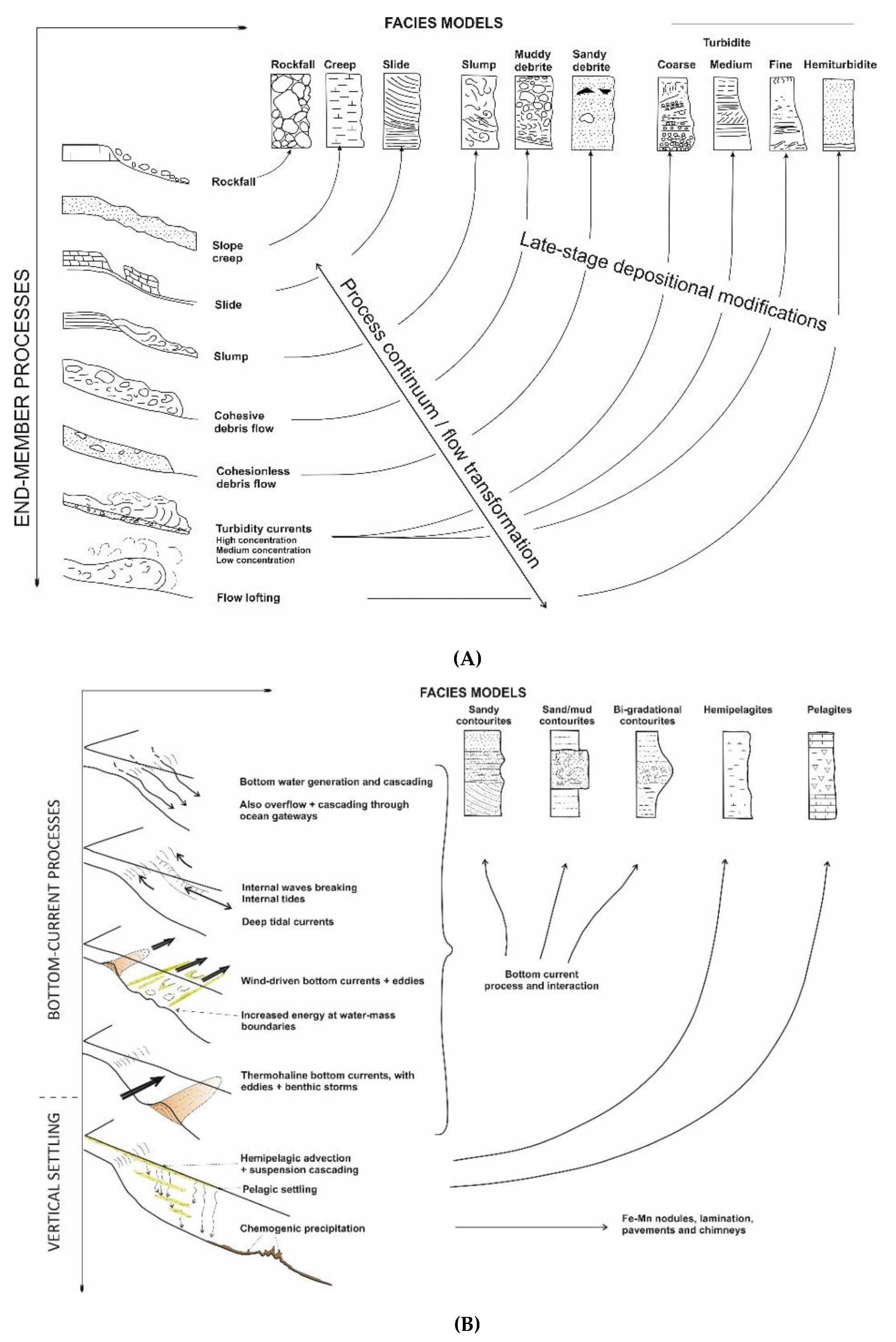
However, there are many subtleties in both process and facies, meaning the picture is more complex, and, hence, controversy arises. Firstly, there are several different types and scales of turbidity current and bottom current, with each of these being able to transport and modify everything from coarse sand and gravel to fine silt and clay-sized material. Both turbidity currents and bottom currents carry (finer) sediment as suspended load and transport (coarser) sediment via bed-load traction across the seafloor. Secondly, there is a continuum between these different processes and facies, which are therefore end-members on a natural spectrum of process and deposit (Figure 1).
The processes of sediment transport and deposition in the natural environment rarely conform to a particular end-member of that spectrum, meaning the deposit will not fit exactly the idealised facies model. Thirdly, all three types can be closely interbedded, particularly in continental margin sedimentary successions. Strong bottom currents are capable of reworking earlier-deposited sediments, winnowing and eroding the sea-floor and of preventing deposition, thereby causing hiatuses and/or hardgrounds in the sediment record. Turbidity currents are equally able to erode or modify seafloor sediments. Pelagic or hemipelagic sedimentation dominates where other processes are absent or rare, but all trace of these deposits can be absent or removed where turbidites dominate or where strong bottom currents have prevented deposition and created a widespread hiatus in sedimentation.
It is in part for these reasons that the distinction between turbidites, contourites and hemipelagites in modern and ancient deep-water systems has long been a matter of controversy [5,6]. The debate is further fuelled by a plethora of published literature that seeks to provide a definitive interpretation of ancient sediment series, either on land or in deep subsurface cores, on the basis of insufficient evidence. There remain, therefore, markedly different sets of criteria published in the literature for distinguishing between the different deep-water facies [7]. Anyone whose work involves deep-water systems and their sediments should be aware of these differences in opinion.
1.2. A Brief History
An extensive body of work on deep-water processes and sediments has been built over the past 150 years since the voyage of HMS Challenger (1872–1876), during which the first systematic study of seafloor sediments was made [8,9]. For many decades since that pioneering expedition, and through the first half of the twentieth century, the deep sea was considered entirely pelagic in nature. Some of the major advances made in understanding pelagic and hemipelagic deposits, both on the present-day seafloor and in ancient deposits on land, have been summarised by [10].
Turbidites were first recognised in the 1950s [11] and the first facies model was developed in [12]. Since that time, turbidites have been one of the better known and most intensively studied deep-water sediment facies. They are now very well known from sediment cores recovered from modern deep-water systems, subsurface (hydrocarbon) boreholes and ancient outcrops now exposed on land. Each new study of a particular turbidite system reveals specific deposit characteristics and facies for that system. The most commonly observed facies have been variously synthesised into a range of facies schemes proposed by [1,2,13,14,15,16,17,18,19], amongst others.
Contourites were first identified a decade later in the early 1960s by Bruce Heezen and co-workers at Woods Hole Oceanographic Institute, USA. The now seminal paper of [20] demonstrated the very significant effects of contour-following bottom currents in shaping sedimentation on the deep continental rise off eastern North America. The deposits of these semi-permanent alongslope currents soon became known as contourites, and the first clear facies models were put forward in [21,22]. The demarcation of slope-parallel, elongate and mounded sediment bodies made up largely of contourites became known as contourite drifts [23,24].
1.3. Synthesis and Distinction
This paper aims to provide a state-of-the-art synthesis of turbidites, contourites and hemipelagites in a fast-moving field of research. It draws on diverse published literature over the past two decades and on synthesis work by the current authors on turbidites [17,25,26] and contourites [17,27,28,29,30,31]. We then propose a methodology and set of criteria for the distinction between the different deposits.
2. Deep-Water Processes
2.1. Turbidity Currents
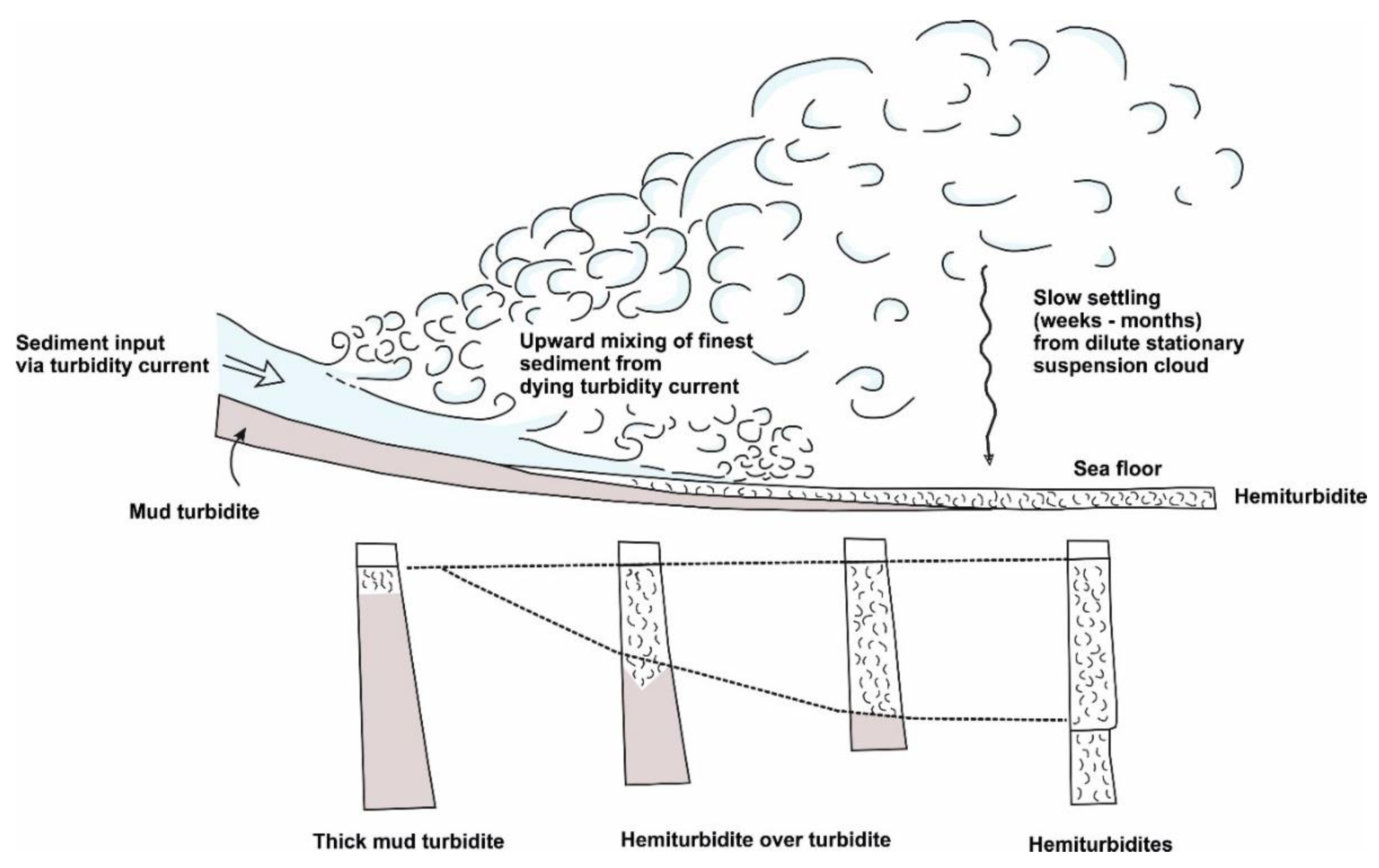
As noted above, it is important to recognise that turbidity currents are part of a process continuum across the spectrum of processes [17]. Mass transport events (e.g., slides and slumps) in proximal slope regions may evolve downslope into debris flows and thence into turbidity currents (Figure 2). Low-concentration turbidity currents can feed material into semi-permanent bottom currents, or, through a process of dilution and flow lofting (Figure 3), lead to a process of hemiturbiditic settling [32,33]. This sort of evolution is part of downslope flow transformation [1]. In addition, gravitational transformation within individual flow events, especially those that are coarse-grained and high-concentration, leads to internal stratification due to vertical gravity segregation. Both types of transformation can result in composite beds with abrupt textural breaks, known as hybrid beds [1,34,35,36,37], or in the separation of the flow into two parts, yielding spatially separated deposits.
Within this spectrum of processes, turbidity currents are one of the most important ways by which fine, medium and coarse-grained material are transferred from shallow to deep water. They are turbulent suspensions of mud and sand (and gravel in some cases) in water which are propelled by the downslope component of gravity acting on the excess density. They may occur as (a) relatively short-lived surge events that travel for only a matter of kilometres downslope or (b) relatively long-lived uniform or steady flows. Surge events may evolve into uniform flows through a process of flow ignition such that an autosuspension process [38] of self-maintenance is generated in the flow. Alternatively, they may be fed by a steady discharge due to prolonged input from, for example, a hyperpycnal flow [39,40]. The uniform flow type permits very long distance transport over tens to several thousands of kilometres, both downslope, over gradients of >5° to <0.5°, and across flat abyssal plains. They can even travel a certain distance in an upslope direction before they come to a halt by a combination of frictional resistance, loss of sediment from the base of the flow and reverse gravitational pull as the flow moves upslope.
Turbidity current properties are becoming better known from observational and experimental data [41,42,43,44,45,46] coupled with theoretical modelling [47,48,49], although there is still a range of uncertainty over some estimates. Based on a considerable volume of earlier work [16,17,50,51,52,53,54,55,56], as well as more recent studies, we can summarise the principal properties as follows (see also [1,26]. Flow velocities have been calculated at 5–25 m s−1 for coarse-grained high-concentration flows, and may exceed 25 m s−1 in some cases. At the other end of the spectrum, fine-grained low-concentration flows may travel for many hundreds of kilometres at velocities <0.5 m s−1. Flow concentration also shows a wide range of values, although this is much more difficult to measure precisely. High-concentration turbidity currents show concentrations of 100–500 kg m−3; above these concentrations they can be referred to as other types of sediment gravity flow (e.g., concentrated density flow, inflated sandflow and debris flow) [1]. Powerful events can result in fast and dense near-bed layers connected to seabed remobilization [43]. At the low end of the spectrum, large dilute mud-rich turbidity currents have very low concentrations of around 0.025–2.5 kg m−3.
Individual turbidity currents are discrete events with very variable recurrence intervals (100–105 y) and of very different sizes. The largest flows are known to overtop channel margins in excess of 500 m in height on many of the large elongate fans (e.g., Bengal, Indus, Amazon and Laurentian). These flows are likely to be several kilometres in width and probably tens of kilometres in length. Much smaller turbidity currents also occur in, for example, lakes and reservoirs. Turbidity currents can be channel-confined or flow across open slopes with little apparent confinement. They can deposit beds between <0.01 m and >10 m in thickness. Mean accumulation rates, therefore, are also very variable, being typically from 0.1 m to >1 m ka−1. The frequency of the occurrence of turbidity currents ranges from 1 ka (approximately) for the distal Bengal fan to one every few years for parts of the Amazon and Congo fan systems, or more frequently still for offshore active rivers and in some lacustrine environments.
Hemiturbiditic sedimentation [32,33] involves flow lofting and upward dispersion from a dilute turbidity current during its final stages of deposition and/or following interaction with a positive topographic obstacle. The fine-grained material carried by the turbidity current disperses above and beyond the final deposit of the normal turbidite, mixes with any background pelagic or hemipelagic material, and deposits slowly by vertical settling. Deposition is episodic (geologically an event deposit) but accumulation is sufficiently slow that a restricted ichnofaunal bioturbation continues throughout. Insufficient data exist to estimate mean rates of accumulation.
2.2. Bottom Currents
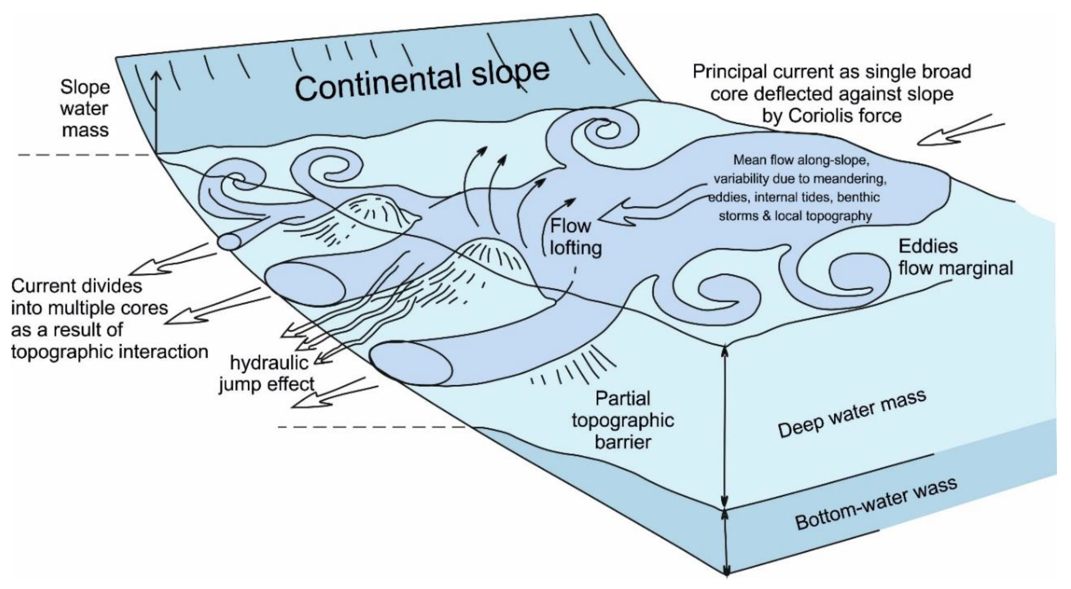
There are at least three different bottom current types that can be recognised as operating in deep-water settings [6,57,58], including (a) wind-driven bottom currents, (b) thermohaline bottom currents and (c) deep-water tidal bottom currents, both barotropic and baroclinic. Internal waves (including baroclinic tides) oscillate along the interface between two water masses of different densities. These are common throughout the oceans but are especially marked and energetic at the depth of the thermocline [59]. Bottom currents are also affected by intermittent processes such as giant eddies, benthic storms, flow cascading and tsunamis (Figure 4). All of these currents and processes are capable of affecting seafloor sediment through their erosion, transport and deposition [6,60,61,62,63,64,65]. Based on a large volume of work, as summarised in these papers, their principal characteristics are as follows.
2.2.1. Thermohaline and Wind-Driven Bottom Currents
The principal characteristics of both thermohaline and wind-driven bottom currents are similar, particularly with regard to how they most affect seafloor erosion and contourite deposition [6,28,29,57,62,64]. They are semi-permanent features in the ocean basins, often long-lived through geological time. They act continuously in affecting sedimentation, rather than as episodic turbidity current events, as described above. They have a net flow alongslope but can also flow upslope, downslope and around and over topographic obstacles or irregularities. After generation near the surface in the source area, they cascade downslope until they find the appropriate density layer for their salinity–temperature properties. At this level they turn, under the influence of the Coriolis force, to flow alongslope.
Bottom currents show (a) broad sluggish movement of water (mean velocity < 0.1 m·s−1) over low gradient slopes and in ocean basins, (b) more constricted intermediate velocity flows (0.1–0.3 m·s−1) over steeper slopes and around topographic obstacles and (c) highly constricted high velocity flows (> 0.3 m·s−1) through narrow gateways and passages and over shallow sills. These velocities may exceed 1 m·s−1 where the flow is particularly restricted or the slope especially steep (nearly 3 m·s−1 has been measured in the Gibraltar Gateway, for example). Mean flow velocity decreases from the core to the margins of the current. Flow velocity is directly affected by changes in slope gradient and other topographic irregularities along its course, and also by current meandering and subdivision into two or more strands around obstacles. Flow concentration is still poorly known but is almost certainly several orders of magnitude lower than those of turbidity currents. Estimates show a range of 0.025–0.25 g m−3, with a tenfold increase under benthic storm conditions (see below).
Bottom currents are highly variable in location, direction and velocity over relatively short timescales (from hours to months). Velocity increase, decrease and flow reversal occur as a result of deep tidal effects. Seasonal changes can result from variation in properties of the water masses generated in the source regions. Large eddies develop at the flow margins, where they peel off and move at high angles or in a reverse direction to the main flow. Eddy kinetic energy, sea-surface topographic variations and surface current instabilities can all be transmitted through the water column and so result in a marked variation in kinetic energy imparted to the seafloor. Such variation can lead to an alternation of short (days to weeks) episodes of higher velocity benthic storms, and longer periods (weeks to months) of lower velocity. Benthic storms can result in further erosion and resuspension of large volumes of sediment, the incorporation of this sediment into the bottom current as suspended sediment load and transport downstream. Deposition occurs during the quieter low-velocity periods. Bottom currents also show longer-period variability (from decadal to millennial), with some of this being able to be attributed to changes in climate and sea-level, for example at the scale of Milankovitch cyclicity, e.g., [66,67].
2.2.2. Deep-Water Tidal Bottom Currents
The specific characteristics of tidal currents in deep water are less well known [6,60]. They have been a continuous process throughout geological time, with a distinctive tidal periodicity. This can lead to alternating normal and reverse current directions and to periods of higher and lower velocity. The focussing effect of deep-ocean channels and gateways leads to maximum current velocities of 0.25–0.5 m s−1 in many slope canyons down to water depths of at least 4600 m, and maximum current velocities as high as 0.75 m s−1 in some cases. These flows may operate at right angles to alongslope bottom currents. However, where the tidal bottom current is directed in parallel with alongslope bottom currents, for example through contourite channels or gateways, the tidal component is added to the alongslope bottom current [68]. This may serve to alternately increase and decrease the mean bottom-current velocity.
2.3. Pelagic and Hemipelagic Settling
Pelagic settling is a process of vertical settling under the influence of gravity by which primary biogenic material and very fine-grained terrigenous or other detritus in the surface waters fall slowly to the seafloor. The rate of fall and hence of sediment accumulation is increased by both flocculation and by organic pelletisation, especially in high productive areas. In oligotrophic open-ocean systems, the process is quite continuous and accumulation is typically very slow, i.e., < 1 cm ka−1. However, in high productive margin areas, the process can occur as pulsed blooms or be seasonal [69]. In this case, sediment is mainly deposited during the onset of eutrophic periods where flocculation of blooming primary producers and production of large faecal pellets by growing zooplankton are favoured.
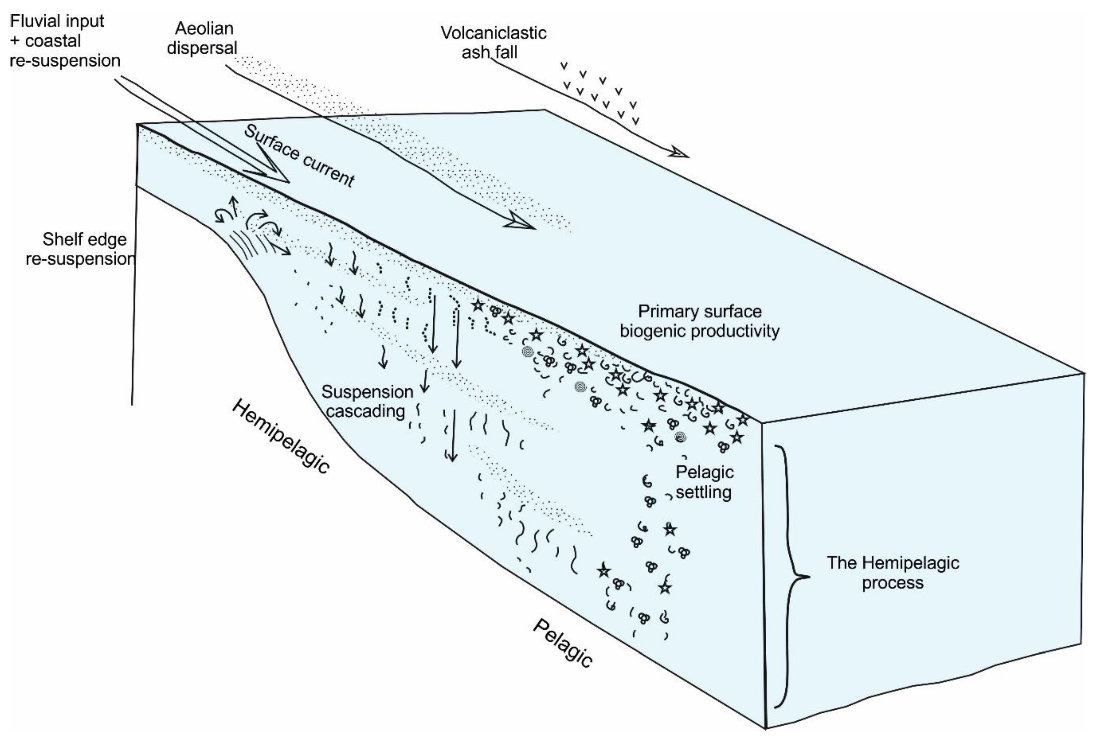
Hemipelagic deposition [70] is a complex process involving both vertical settling and slow lateral advection through the water column (Figure 5). The driving forces behind this lateral advection include the inertia of river plumes (both within the water column and at the surface), glacial meltwater diffusion, turbid layer plumes, internal tides and waves and other slowly moving midwater currents. Cross-shelf and/or shelf-to-slope advection of selected fine particles, seafloor re-suspension and off-shelf spillover of fluid mud may also contribute to this process [71]. Between 1000 and 2000 m water depth, modern slope sediments are generally enriched in organic carbon older than 1000–2000 years. Hemipelagic deposition is a continuous process with very variable rates depending on the nature of biogenic and terrigenous inputs, e.g., 2 cm ka−1 on continental margins with little terrigenous input, 10 cm·ka−1 for black shale hemipelagites in areas of high upwelling and over 20 cm·ka−1 for high latitude glaciomarine hemipelagites.
2.4. Flow Transformation, Process Interaction and Reworking
As already noted, flow transformations commonly occur within turbidity currents and related mass gravity flows via downslope evolution of flow type (debris flow to high-concentration turbidity current to low-concentration turbidity current to a flow-lofted turbidity cloud) and via gravitational within-flow segregation (debris flow, turbidity current and grain flow alternation) [1,34,72,73,74].
Close interaction between different processes is also common (e.g., [1,17,57,60,61]). Both turbidity currents and bottom currents will directly affect the slow settling of hemipelagic material, incorporating this fine-grained, often biogenic, material into their deposits. Bottom currents will similarly pirate the fine suspended load of distal turbidity currents [60] and of the upper parts of flows that have over-spilled channel levees. The sudden introduction of turbidity current material into bottom currents will affect the nature and concentration of the flow as well as the composition of the deposit. Both interbedded and hybrid facies will result. Deep tidal currents have the potential to interact with and modify the properties (e.g., velocity) of thermohaline and wind-driven bottom currents, especially where their velocity is enhanced in restricted passageways or channels [68].
Downslope turbidity currents, alongslope bottom currents and deep tidal currents have the potential to rework any previously deposited sediment on the seafloor. The extent of reworking, the distance of transport as bedload and the degree of resuspension and incorporation into the over-riding flow will depend on both the properties of the flow (speed, capacity and competence) and the nature of the sediment (grain-size, competence and consolidation).
3. Turbidite Deposits
3.1. Definition and Turbidite Facies
Turbidites are defined as all those sediments deposited by turbidity currents. They are geologically instantaneous event deposits, although the deposition of a single turbidite bed may take minutes (gravels and coarse sands) to a few days (fine silts and muds). Turbidites have been one of the better known and most intensively studied deep-water sediment facies since they were first recognised in the 1950s [11] and the first facies model was developed in [12]. They are now very well known from sediment cores recovered from modern deep-water systems, subsurface (hydrocarbon) boreholes and ancient outcrops exposed on land. They include a very wide range of deposit types, from very thin-bedded (<3 cm) silt-mud layers to very thick-bedded (1–10 m, rarely more) graded gravel–sand–mud units.
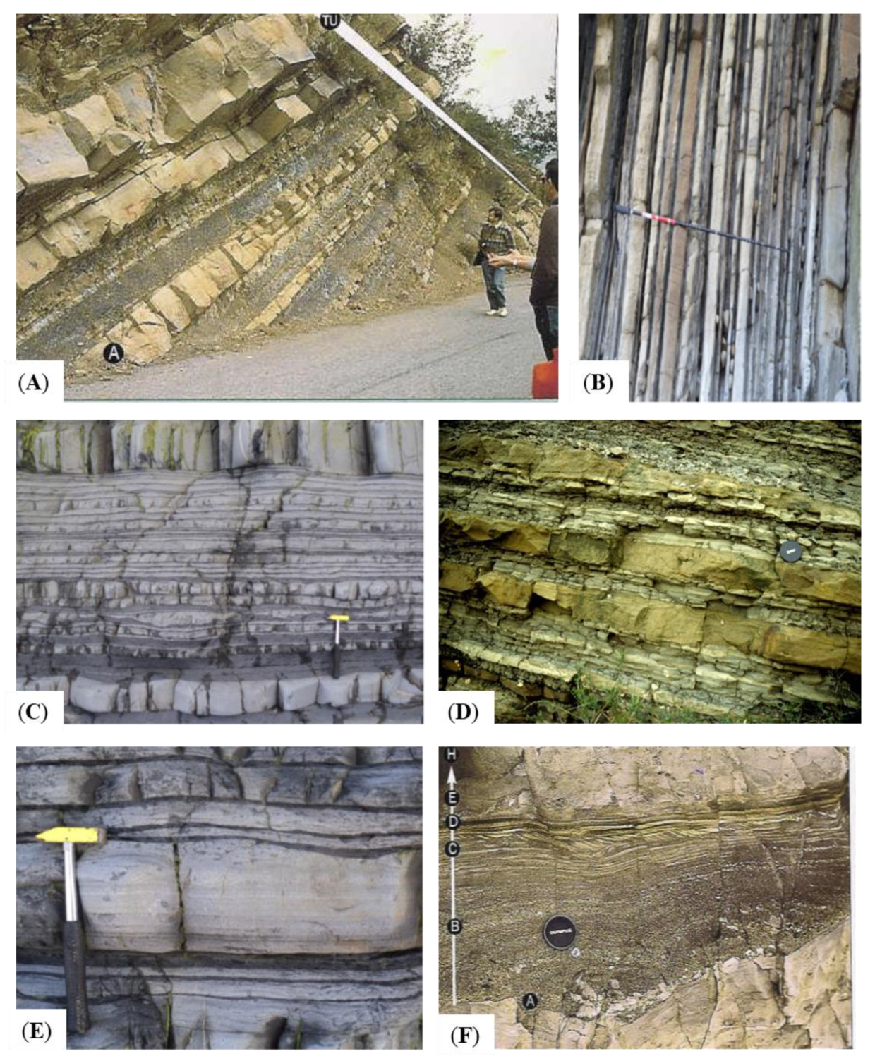
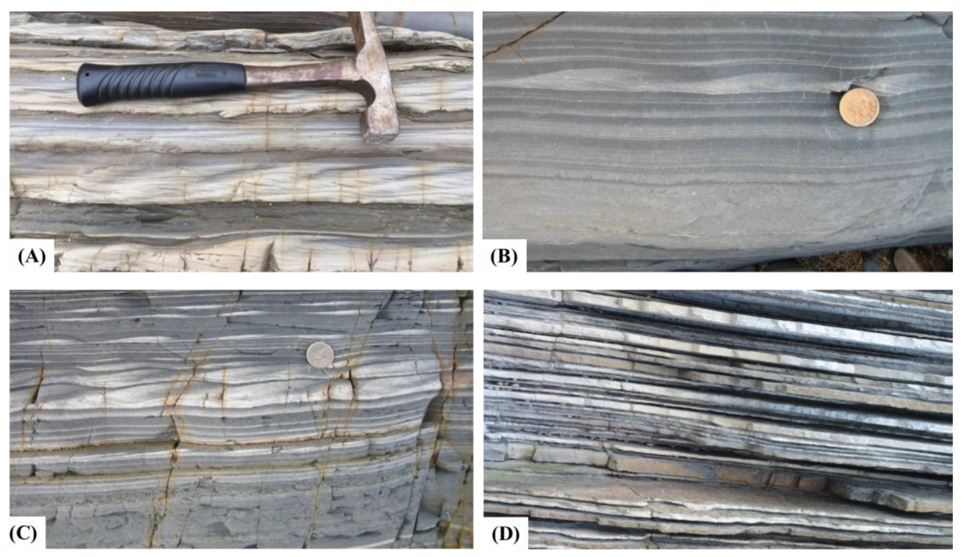
There are very many different individual turbidite facies recognised. The most common of these have been variously synthesised into a range of facies schemes proposed by [1,2,13,14,15,16,17,18,19], amongst others. We show the principal facies models for turbidites in Figure 6, Figure 7, Figure 8, Figure 9, Figure 10, Figure 11 and Figure 12. The deposit characteristics, as described below, are illustrated with photographs in Figure 7, Figure 9 and Figure 12. They are based on a long and extensive history of turbidite study and publications, as synthesised in [1,2,13,14,15,16,17,75,76,77], amongst others.
3.2. Turbidite Characteristics
Bedding. Turbidites generally show very well-defined bedding. Distinct beds with sharp bases and sharp to gradational tops are the norm. Interbedding of well-defined sandstone and mudstone beds is one of the distinctive characteristics by which turbidites are recognised. Individual beds vary widely in thickness, from <1 cm to >10 m, whereas the frequency of bed thickness typically follows a power-law distribution in many turbidite successions.
Structures. Primary sedimentary structures indicative of deposition by unidirectional currents are very common, especially in thin- to thick-bedded turbidites. These include parallel and cross-lamination/bedding, lenticular and discontinuous lamination (in thin and very thin beds) and spaced to indistinct lamination (in thick and very thick beds). Large-scale cross-bedding or dune-cross-bedding is rare, except where it occurs by flow by-passing on the channel floor. Parts of beds as well as whole beds may be entirely structureless, at least to the naked eye. This is especially true for thick and very thick beds, which may also show well-developed water-escape structures (pipes, dishes and convolute lamination) indicative of very rapid deposition. The bases of beds commonly show loads, flame structures and scours (flutes and grooves). Sedimentary structures are typically organised systematically into sequences through normally-graded beds. These form the basis of the turbidite facies models described below.
Bioturbation. Turbidites commonly develop a top-down ichnofacies, reworking the upper parts of a bed while leaving the lower parts unaffected. Bioturbation is best developed where the repeat frequency of turbidite events is relatively low, meaning the turbidites are interbedded with more slowly-accumulated hemipelagites and/or contourites. Detailed studies have revealed distinctive ichnofacies for different turbidite settings [79,80,81,82]. In a submarine fan environment, thick-bedded sandstones of channel axes are characterised by low-intensity and low-diversity Ophiomorpha and Thalassinoides ichnofacies. Intensity of burrowing and diversity of the assemblage increases across the channel margin (Pychosiphon–Thalassinoides ichnofacies) to the overbank-levee environments. In these thin-bedded sand-mud turbidites, a diverse Planolites–Chondrites ichnofacies dominates. In a slope apron environment, typified by the Nereites ichnofacies, bioturbation is generally more intense and diverse. The Ophiomorpha sub-ichnofacies (with Diplocriterion and Scolicia) characterises the mid-upper slope turbidites, whereas the Paleodictyon sub-ichnofacies characterises the distal slope.
Texture. Sedimentary textures of turbidites yield important information on the capacity and competence of the turbidity current, as well as on the distance of transport and likely provenance. Mean grain size ranges from gravel to sand to silt/clay sizes, for coarse, medium and fine-grained turbidites, with isolated clasts in excess of 1 m length in some examples. Sorting is equally variable, but generally better (i.e., moderate to well-sorted) for fine- and medium-grained turbidites. Normal grading is the most common feature observed, either through the whole bed or at the top/base only, although completed ungraded beds also occur. In coarse-grained turbidites there may be a basal zone of reverse-grading overlain by a normally graded or ungraded bed. In fine-grained turbidites, graded silt-laminated units are typical in which the alternation of silt and mud laminae is the result of shear sorting through the basal boundary layer of the flow during deposition [52].
Grain-size breaks. Abrupt changes in grain size across an intra-bed surface are a common feature of turbidites everywhere [83,84]. Five types were recognised in [85] between coarse and fine sand, medium and fine sand and between sand and mud. We would add two further marked breaks, namely, between gravel and sand and between silt and mud.
Fabric. Turbidites commonly show well-developed long-axis grain or clast alignment parallel to the flow direction. Grain and clast imbrication shows up-flow inclination. Strong flow-parallel and bed parallel clay and silt alignment is typical of mud turbidites.
Composition. Turbidites are most commonly siliciclastic, bioclastic, volcaniclastic or of mixed composition. More rarely, they are composed of chemiclastic material, i.e., reworked evaporites. They are characterised by (a) allochthonous elements introduced into an area so that the turbidite composition may differ markedly from that of in situ interbedded facies and (b) material derived from a shallow water and/or continental provenance.
3.3. Turbidite Facies Models
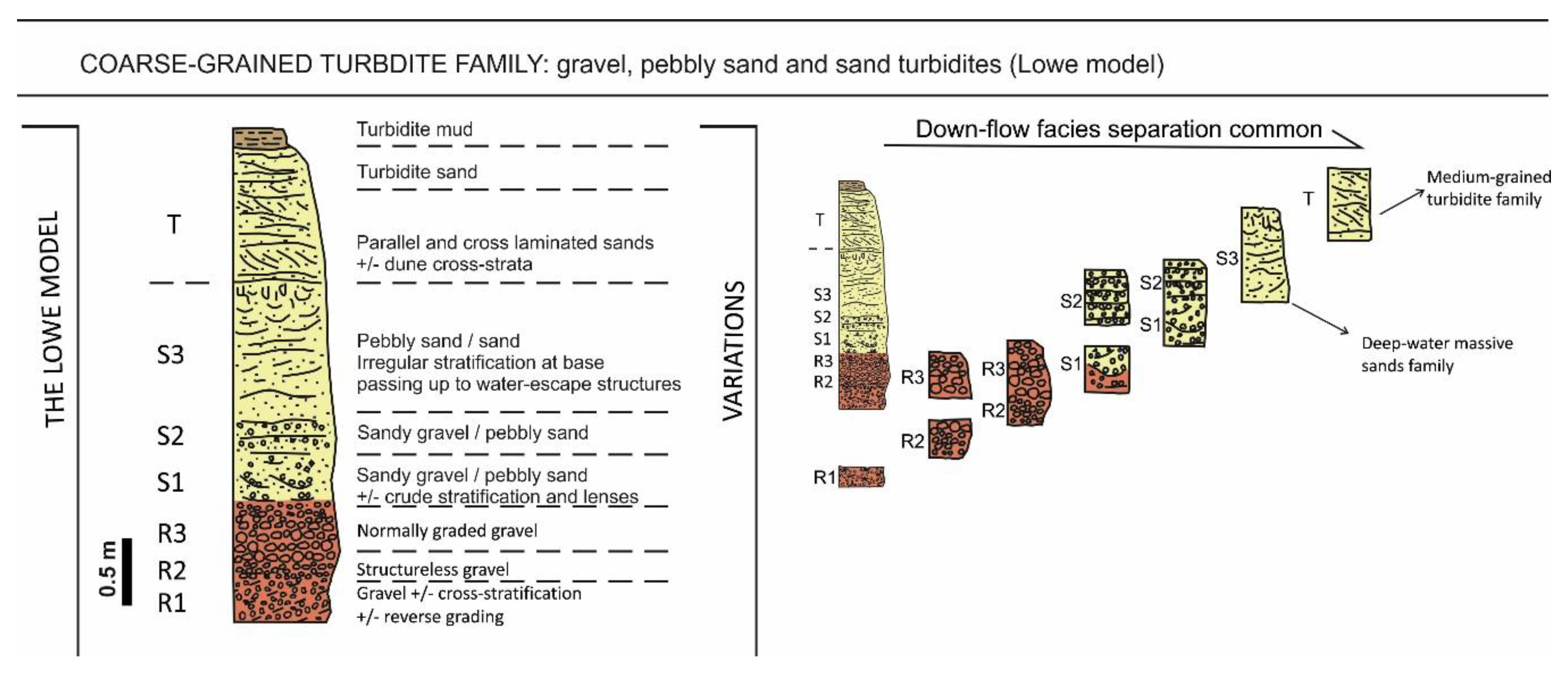
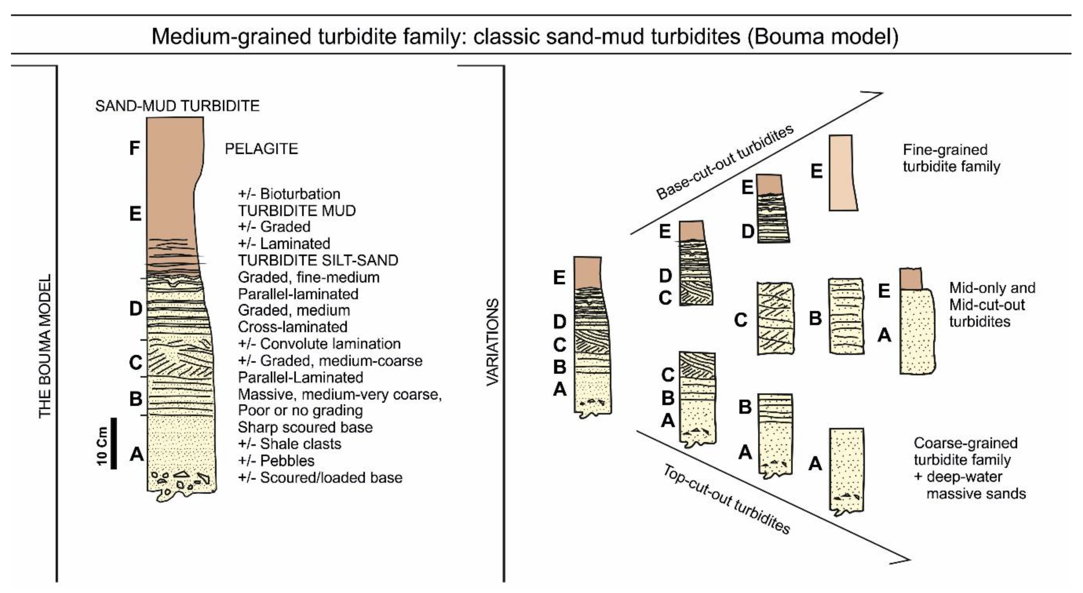
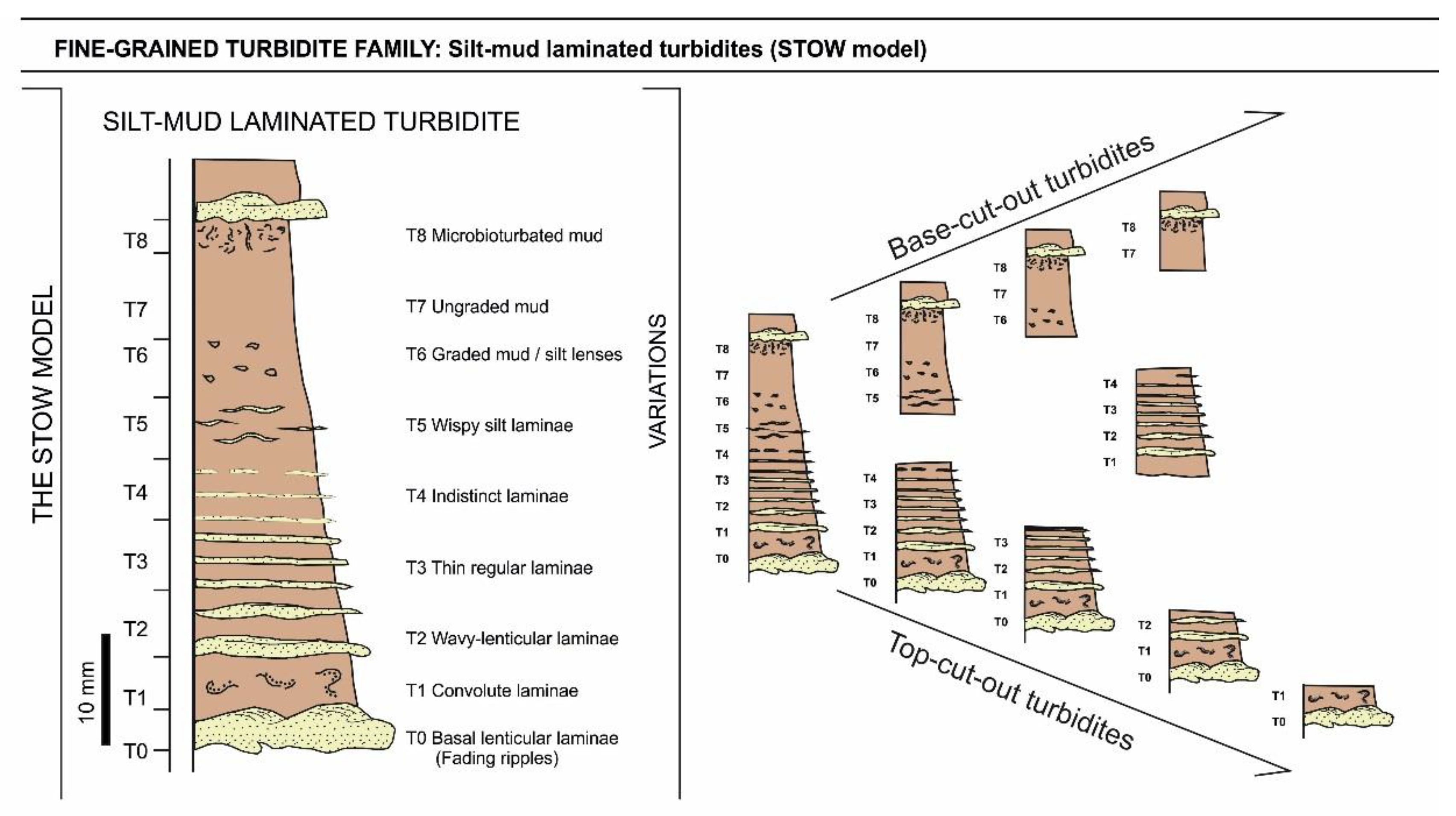
These composite characteristics from multiple datasets have been synthesised into facies models for coarse-grained turbidites [25,34,78,86], medium-grained turbidites [12,87], and fine-grained turbidites [21,88,89]. For convenience, these are referred to as the Lowe, Bouma, and Stow sequences or facies models, after the authors who first established each respective scheme. Each of these facies models shows a characteristic sequence of sedimentary structures and grading which reflects deposition from a single turbidity current event (Figure 6, Figure 7, Figure 8, Figure 9, Figure 10 and Figure 11). They are event deposits. The different structures are referred to as divisions within the sequence. The Stow sequence (T0–T8) (Figure 10) is more or less equivalent to the D-E divisions of the Bouma sequence (A–E) (Figure 8), or the E1–3 divisions of [88].
Complete sequences are generally present in <10% of observed turbidites. More common are partial sequences in which the same order of divisions is preserved but not all are present in any one bed. For each sequence, the lower divisions represent deposition from the current when it is more energetic and the upper divisions when it is less energetic. For a single turbidity current, this can be achieved from more proximal to more distal, respectively, and also from channel axis to overbank. The same high to low energy regime applies to Lowe, Bouma and Stow turbidites. In some cases, Lowe divisions are overlain by Bouma divisions in a single bed or Bouma divisions by Stow divisions. Rarely, all three can occur in megaturbidites.
Fine-grained and medium-grained turbidites are best characterised by the Stow and Bouma models. These are shown, together with a typical range of partial sequences, in Figure 8, Figure 9, Figure 10 and Figure 11. Modern and ancient examples of both types are shown in Figure 9 and Figure 12. They represent deposition from uniform turbidity currents in the depletive regime of the Kneller matrix [90]. They are the most abundant and widespread types of turbidite in both marine and lacustrine settings. Coarse-grained turbidites are best characterised by the Lowe model (R1–S3) (Figure 6). All three models include distinct grain-size breaks, although these are not generally indicated on standard figures. For the Stow sequence, the most marked break is between the T0 and T1 divisions; for the Bouma sequence, between sand and mud in partial sequences (AE and CE divisions); and for the Lowe sequence, between gravel and sand divisions (R3–S1).
Variations from the Standard Models
There are several variations from the standard facies models described above, in addition to the widespread occurrence of partial sequences. These variations may arise due to (a) flow transformations during a single downslope event, between debris flows and within high to low concentration turbidity currents, (b) the actual process and rate of deposition through the traction carpet or boundary layer and (c) the well-documented process-facies continuum of turbidity currents and turbidites, as outlined above.
In terms of composition, the Lowe, Bouma and Stow models were developed from siliciclastic systems but have been shown to apply equally to bioclastic and volcaniclastic turbidites [91,92,93]. Some differences have been documented for calcareous bioclastic turbidites. For example, calcarenite turbidites may display a large-scale dune cross-bedded division, which is typically missing from siliciclastic turbidites. Calcilutite turbidites show a less distinct silt laminated division than siliciclastics, and a more gradual, often reverse-graded, upward transition into hemipelagic or pelagic ooze [55,91]. Too few examples of chemiclastic turbidites have been described to establish what differences they may display [94].
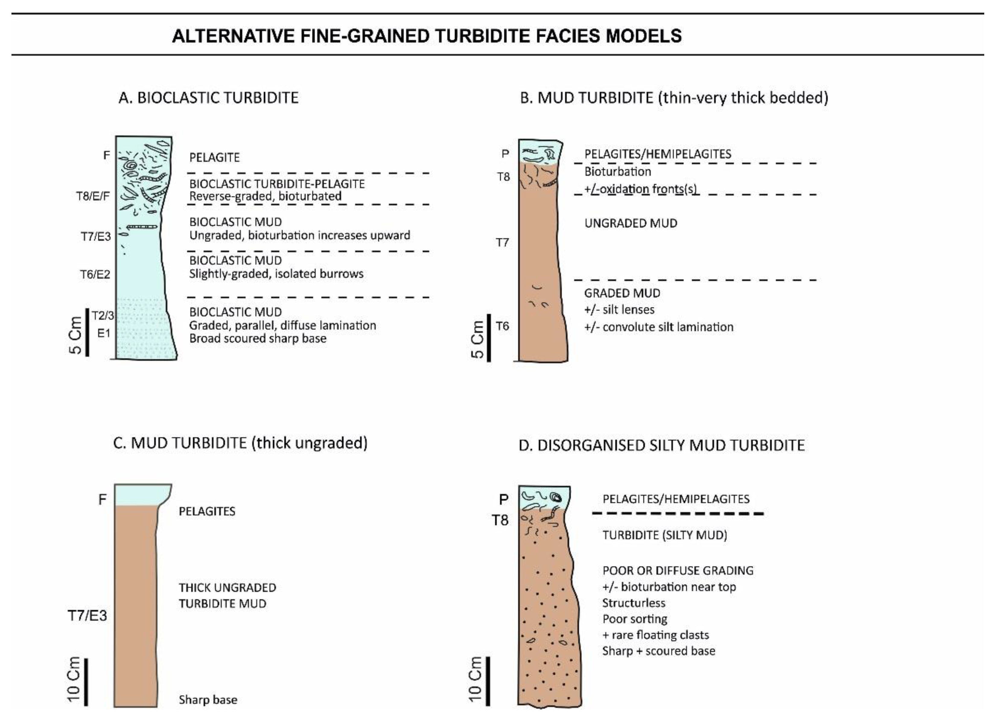
In distal turbidite environments and channel levee-overbank settings, silt beds (>70% silt-sized particles) are more abundant than sands and commonly occur as thin or medium-bedded turbidites. These silt beds exhibit the same suite of structures (the Bouma sequence) as sand-mud turbidites. Ungraded structureless silts are found more proximally and can be attributed to AE-division Bouma turbidites. Strachan et al., 2016 [36] describes other variations of silt and silty-sand turbidites with a wide ranging of grading styles, including ungraded, reverse and normal-graded silt turbidites from proximal settings (Figure 8).
Medium- to very-thick-bedded mud turbidites are known from a variety of environments, including ponded basins [72,95,96,97], channel-fill successions [17], open slope and base-of slope settings [70] and distal fan lobes [98]). Thick mud turbidites may appear completely structureless or homogeneous and are also known as homogenites or unifites. In distal and basin plain settings they may be associated with hemiturbidites, the result of very slow deposition from the suspension cloud that develops above and beyond the feather edge of true turbidite deposition [32,33]. Hemiturbidites have the same composition as the associated mud turbidites but are structureless, ungraded and very fine-grained, and are bioturbated throughout. Very-thick-bedded and structureless sand turbidites are also common in certain settings (e.g., channel-fill and confined basins). These beds are part of the deep-water massive sand facies association [99].
There is a group of thin-, medium- and thick-bedded turbidites that do not show clear Stow or Bouma sequences, have absent or very indistinct lamination and do not have a clear separation between their sand/silt and mud fractions [26,55]. Some show distinctive normal grading whereas others have poor grading and abundant small mudstone clasts. We interpret these as the deposits of immature, surge-type turbidity currents. They may have developed from cohesive debris flows.
4. Contourite Deposits
4.1. Definition and Facies
Contourites are defined as all those sediments deposited or substantially reworked by the persistent action of bottom currents [28,57,100,101]. The term ‘contourite’ was originally used specifically for sediments deposited in the deep sea by contour-parallel (alongslope) bottom currents driven by thermohaline circulation. It has since been widened to embrace a range of sediments affected by different types of current, including those that act in shallower water [101]—i.e., upper slope and outer shelf depths—as well as in large lakes and inland seas. These are referred to as shallow-water and lacustrine contourites, respectively.
A wide range of different contourite facies are now recognised, as illustrated in Figure 13. These range in grain size from fine muds, through silts and sands, to sand and gravel lag deposits, and are often poorly sorted mixtures of different grain size fractions. In composition they are equally varied, including siliciclastic, bioclastic (calcareous and siliceous), volcaniclastic, and chemogenic (manganiferous) varieties, commonly displaying a mixed composition.
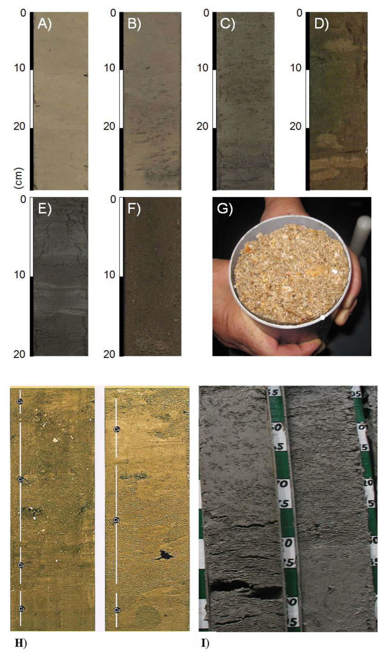
Siliciclastic contourites are well known from a wide range of marine settings, including continental slopes, abyssal plains and shallow-marine and high-latitude settings, and are most easily recognised as part of large-scale contourite drift deposits. They commonly occur as thick featureless units which are poorly bedded, with a more or less cyclic alternation of muddy, silty and sandy facies, characterised as bi-gradational sequences (Figure 13). In any one location they tend to show a very uniform, monotonous aspect in terms of colour, texture and composition. They are generally highly bioturbated, often with an indistinct mottled appearance, and may further show distinct burrows of varied (deep-water) ichnofacies [103,104]. There may be rare primary lamination present (partly destroyed by bioturbation), diffuse and indistinct, in places marked by colour change and in places by irregular winnowed concentrations of coarser material.
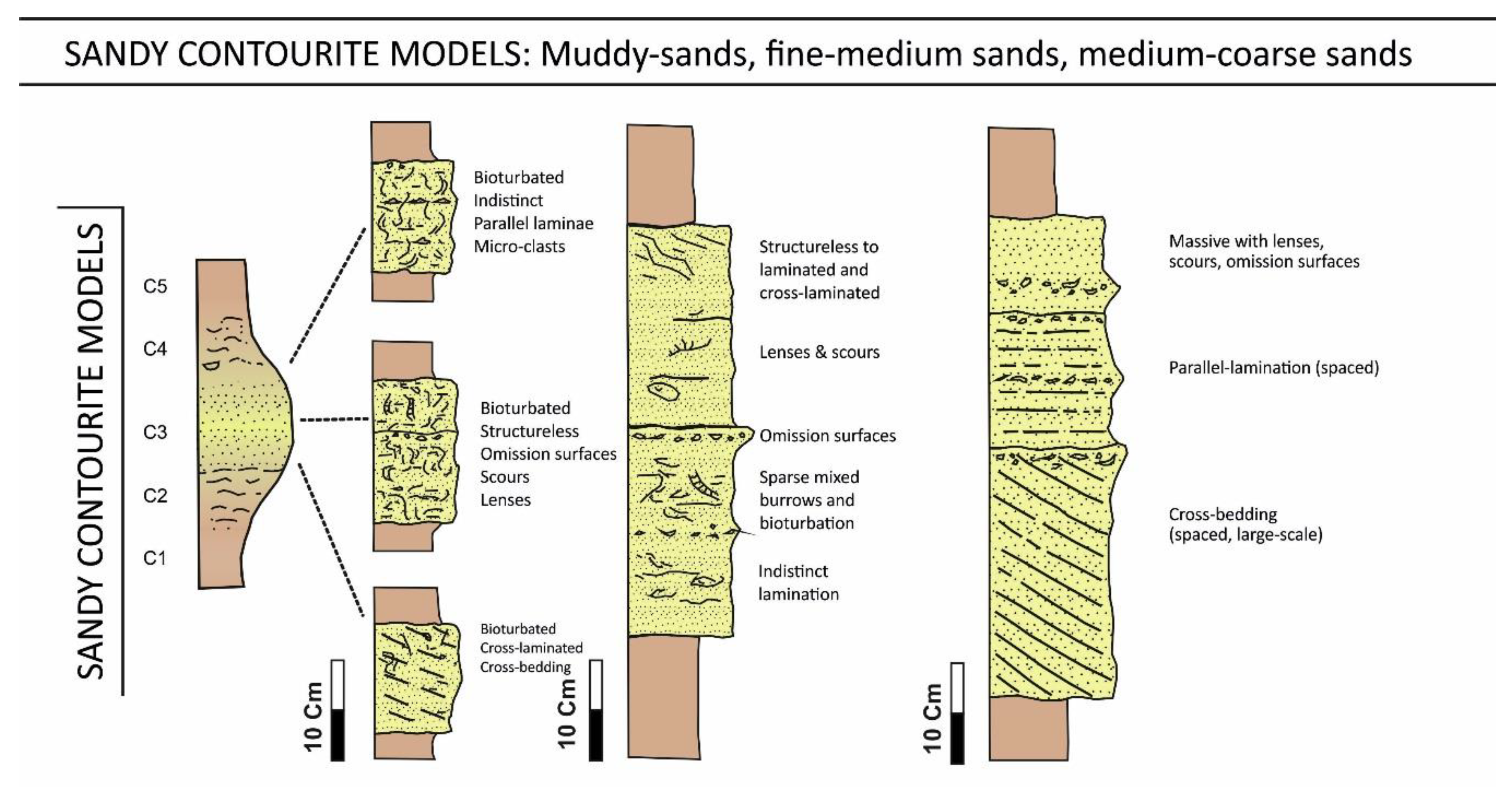
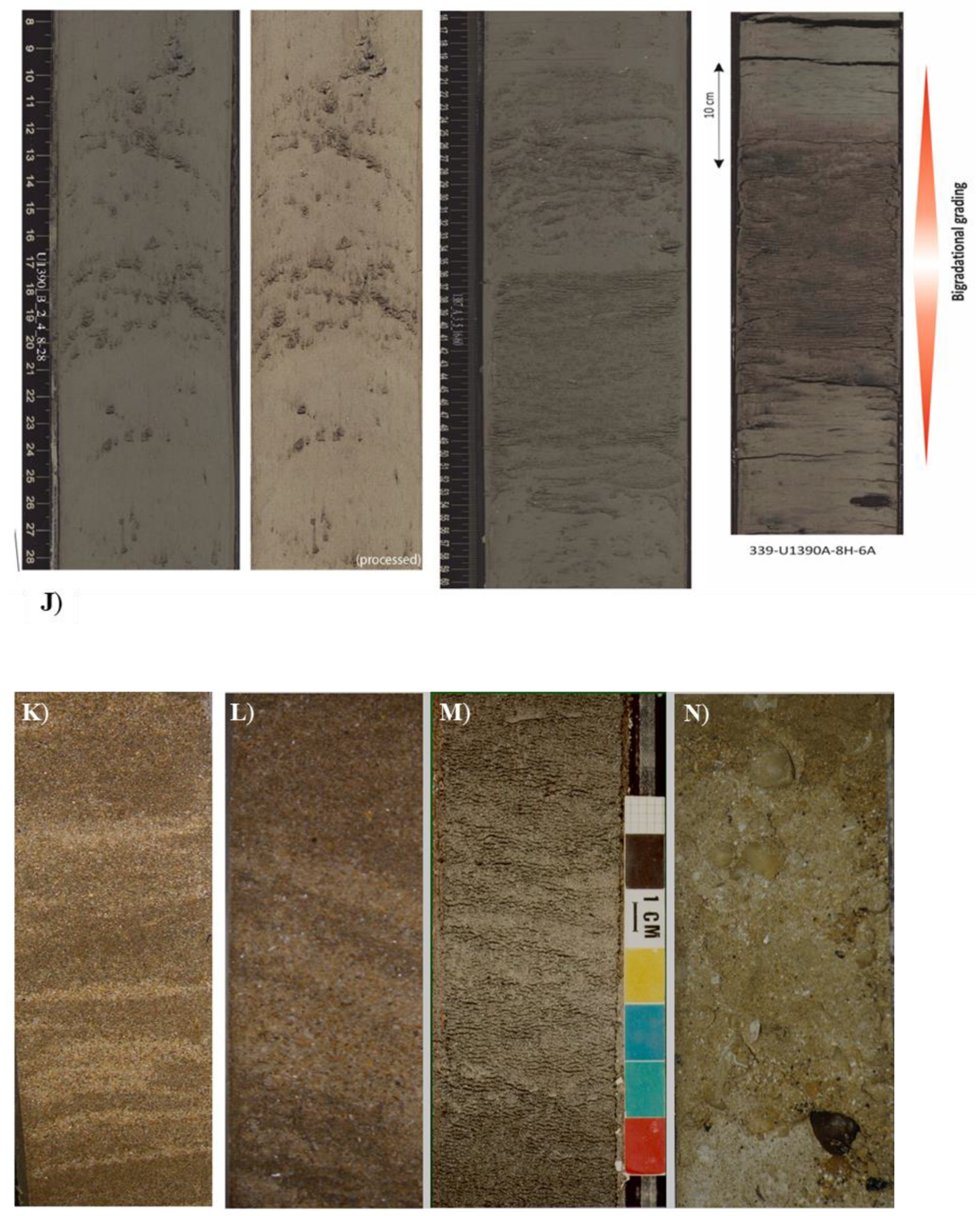
Sandy contourites (Figure 14) are known to make up thin to thick (5–500 m thick) sheeted drifts, covering extensive areas of the seafloor over the outer shelf/upper slope, across slope terraces and in oceanic gateways and flooring contourite channels. In such areas, the seafloor is typically ornamented by a range of current-induced bedforms (ripples, dunes and furrows) and the underlying sediment may preserve internal sedimentary structures such as cross-lamination, large-scale cross-bedding and parallel lamination. Structureless and bioturbated sands are also common.
Calcareous bioclastic contourites are prevalent wherever the dominant supply to the bottom-current and drift systems is made up of carbonate material. This may be from erosion and downslope reworking of carbonate banks and bioherms, or from pelagic fall-out, especially in regions underlying high primary productivity. Apart from compositional differences, their characteristics are otherwise similar to those of siliciclastic contourites. These calcicontourites are well known from ancient contourite successions exposed on land, which are described in a subsequent section.
We show the principal facies models for contourites in Figure 13 and Figure 14. The deposit characteristics, as described below, are illustrated with photographs in Figure 15 and Figure 16. As for turbidites (above), these are based on a long and extensive history of contourite study and publications, as synthesised in [1,3,15,17,28,77,106,107,108,109], amongst others.
4.2. Contourite Characteristics
Bedding. Contourite bedding is poorly developed or indistinct in thick muddy successions developed under low-energy bottom-current systems but becomes more evident with an increased silt and sand component delivered by higher-energy currents. The sand supply is influenced by long-term (5000–20,000 y) fluctuations in mean bottom-current velocity, as well as by variation in sediment supply, either turbidite or pelagic influx. Sand-rich contourite successions are generally well-bedded due to common mud-rich interbeds.
Structures. Contourites recovered from mud-rich drift systems are characterised by a notable absence of clear, distinct lamination and by the presence of common to abundant pervasive bioturbation. In some cases they appear completely homogeneous, whereas in other cases they show indistinct and discontinuous parallel lamination, partial grain alignment, sub-horizontal to irregular erosion surfaces, thin layers and lenses of coarser material. Cross-lamination is only rarely present in silts and fine sands.
The paucity of cross-lamination is somewhat surprising as the present-day seafloor beneath bottom currents is commonly covered with ripples, dunes, lineation and other current-induced bedforms. However, the presence of pervasive bioturbation rather than lamination might be explained by relatively low rates of semi-continuous contourite accumulation, meaning bioturbation is able to keep pace with deposition and effectively destroy most primary lamination. For muddy contourites, the low current velocities and sediment concentrations are insufficient to result in any clear primary lamination, although minor erosion/non-depositional surfaces and silty/sandy lens and layers are evidence of repeated and alternating phases of erosion, winnowing and deposition.
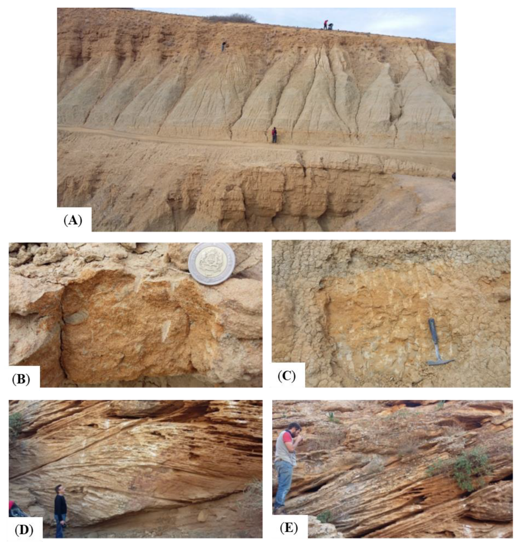
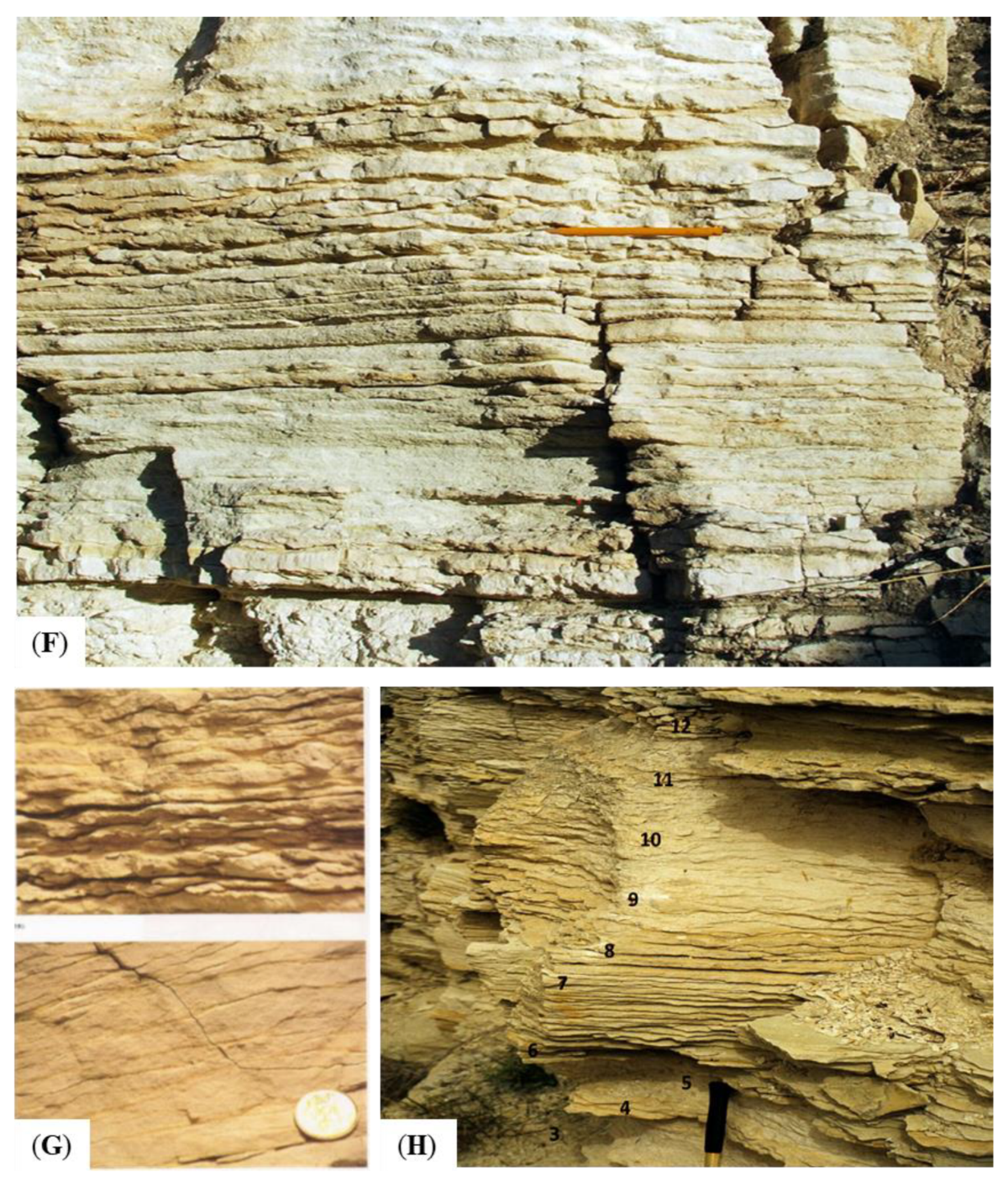
Laminated and cross-laminated sandy contourites are known from beneath higher-velocity bottom currents with large-scale bedforms (e.g., dunes) evident on the sea-floor. The lamination is distinct, typically diffuse and widely-spaced, and may be associated with limited bioturbation. The presence of such structures clearly indicates bedload tractional movement of granular sediments by the bottom current. Preservation of the primary lamination is due to rapid sedimentation, high current velocity, and/or the dearth of organic matter. Ancient contourites with cross-lamination preserved have been documented from the Miocene in Morocco [110] and Oligocene in Cyprus [111].
Bioturbation. Pervasive bioturbation has long been recognised as a distinctive feature of contourites [28,100,103], with well-developed bioturbation common throughout the beds (rather than top-down as for turbidites (see above)). There is a clear link between ichnofacies assemblage and a combination of current strength and organic matter supply. Strong bottom currents deposit sand-rich contourites which are relatively poor in organic matter and which have common omission surfaces and hiatuses. Long-term omission yields indurated discontinuity surfaces marked by a stiff- to hard-ground ichnofacies; where overlain by sand, a typical Glossifungites ichnofacies is present, and, where covered by mud, a sharp-walled piped zone results. The upper parts of sandy contourite layers contain biodeformational structures resulting from ploughers and passively ventilated tube systems. These burrows become overprinted by deeper penetrating ones like Skolithos, Scolicia and Planolites, in addition to the U-shaped Teichichnus deep-dwelling crustacean burrows such as Thalassinoides and Gyrolithes.
Weak bottom currents deposit mud-rich contourites that are generally richer in organic matter. Within such organic-rich muds, oxygen consumption by benthic animals and bacteria may lead the anoxia of pore water at shallow burial depths. The ichnofauna is both small in size of individuals and low in diversity (including monospecific populations). Chondrites and Trichichnus are often dominant, together with Phycosiphon, Planolites and less specific ‘mycellia’ traces. Pyritisation is common. Where omission surfaces occur, vertical tubes and Glossifungites ichnofacies are evident.
Contourite bi-gradational sequences (see below) show a distinctive variation in ichnofacies linked to current strength through the sandy (larger and more diverse assemblage), silt-mottled and muddy sequence divisions (smaller and less diverse assemblage).
Texture. The sedimentary texture of contourites provides important information on the nature of transport and deposition by bottom currents [63]. Mean grain size, and in particular, the sortable silt component, is a key indicator of flow speed [112,113]. Bivariate cross plots (e.g., mean size versus sorting) reveal the carrying capacity and degree of winnowing, as well as the input of external material to the bottom current [105]. Grain-size distribution spectra are more or less unimodal, and, on cumulative frequency plots, commonly show a tripartite subdivision into a coarser-grained bedload fraction moved by traction, an intermediate fraction moved as saltation load, and a finer-grained fraction transported wholly in suspension. Still coarser-grained contourites (coarse sand and gravel-rich) are moved wholly and intermittently as bedload.
The dominant grain size of mud-rich contourite drift deposits is clayey silt and silty clay (125–0.5 μm). They commonly show poor sorting (1.4–2.5 phi) and may contain significant (up to 15%) sand-size material (>63 μm). The sand fraction is typically made up of biogenic tests (calcareous or siliceous) or ice-rafted material at high latitudes. Sandy contourites are mostly fine- to medium-grained and are more rarely coarse-grained or pebbly. In many cases, they are only moderately to poorly sorted (0.8–2 phi), partly as a result of bioturbational mixing with mud grade material, whereas the laminated sands may be moderately well-sorted (0.5–0.7 phi).
Bi-gradational grading is the norm for most mud–sand contourite successions (see Contourite Facies Models below). Individual bi-gradational units are typically between 0.5 m to 3.0 m in thickness. They are less evident in finer-grained mud-dominated successions and are more truncated (or absent) in sand-rich successions.
Fabric. The sedimentary fabric or microfabric of contourites is still poorly known, and some conflicting results have been published. There is some evidence that grain alignment of silts and fine magnetic particles (using anisotropy of magnetic susceptibility measurements) shows flow-parallel trends. However, other data indicate a more chaotic grain orientation. A recent detailed study using scanning electron microscopy with automated image analysis has revealed that both silt and clay microfabrics show a combination of preferred bed-parallel alignment, semi-random/preferred and wholly random grain orientation. This is interpreted as the result of flow shear during deposition creating a weak to strong fabric, depending on current strength, and pervasive bioturbation tending to disrupt that fabric [114].
Composition. Contourites vary in composition from one region to another, as evidenced by the different facies types, e.g., siliciclastic, calcareous, volcaniclastic, and others (see above). Quite commonly, they display a mixed terrigenous-biogenic composition which can be quite uniform throughout any one contourite depositional system. This uniform admixture of components indicates a range of sources and supply routes, as well as depositional mixing of components, which has been persistent across time. These include (a) the vertical settling of pelagic material from the surface, (b) slow horizontal advection and suspension cascading of hemipelagic material, (c) downslope input from turbidity currents and hyperpycnal plumes, (d) downslope flux via spillover processes and (e) alongslope supply via the bottom current from material that has been eroded, winnowed and re-suspended from the seafloor upstream from or adjacent to the site of deposition.
Certain processes and hence component inputs will dominate in different contourite settings. In most cases, the sand-sized fraction will show partial fragmentation, rounding and iron-staining, which is all indicative of bottom-current transport as saltation load and bedload.
4.3. Contourite Facies Models
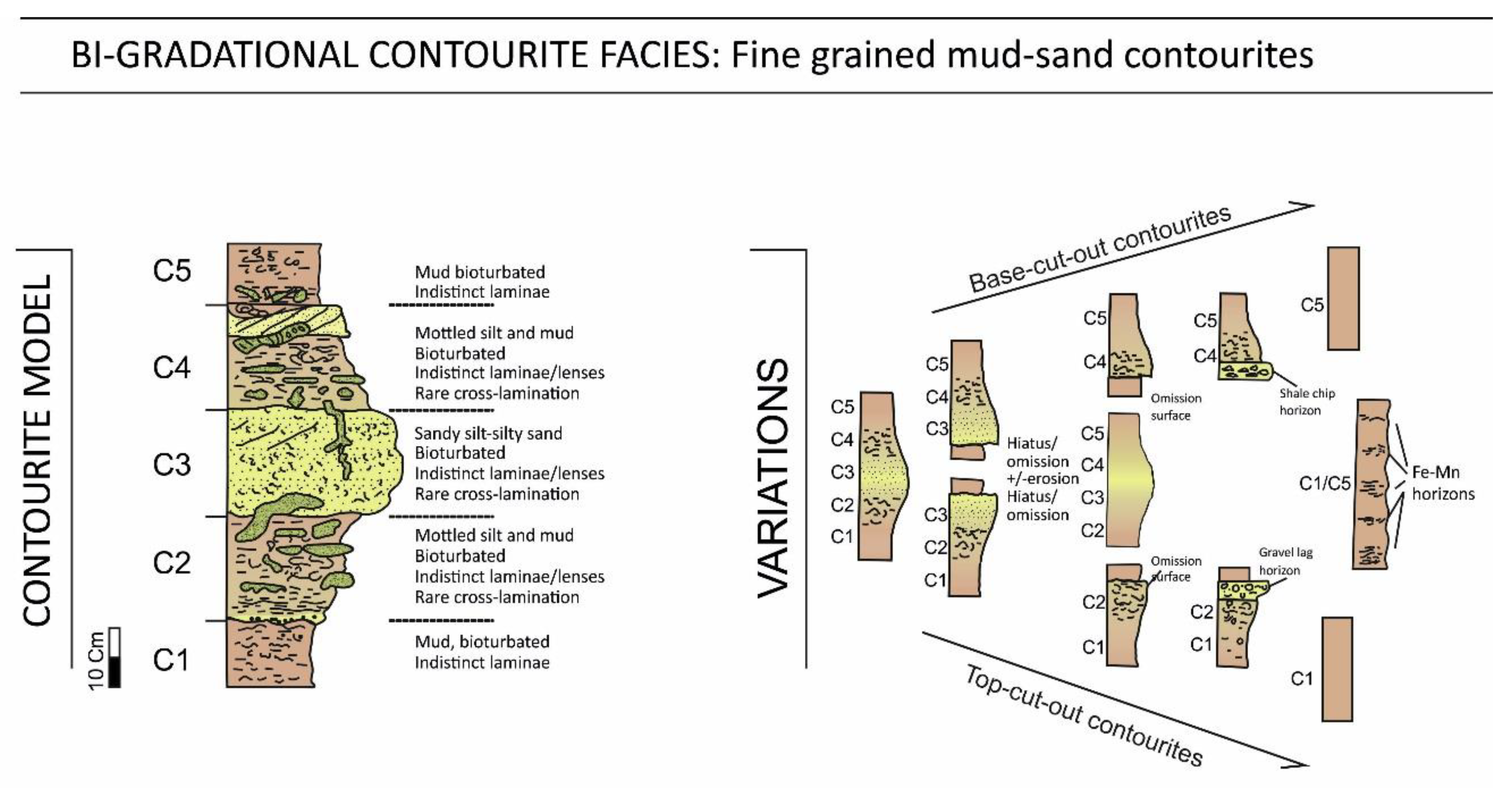
Separate facies models for muddy and sandy contourites were originally proposed in the late 1970s [100,115]. Subsequent work demonstrated that these muddy and sandy facies, together with intervening silty contourites, commonly occur in composite sequences or partial sequences a few decimetres in thickness (typical range 0.5–3 m). The now standard bi-gradational facies model shows overall negative grading (coarsening-up) from muddy through silt-mottled to sandy contourites and then positive grading (fining-up) back through silt-mottled to muddy contourite facies [116]. Well-defined sedimentary structures are generally absent, in part because they have been thoroughly destroyed by bioturbation. There may be an indistinct and discontinuous parallel lamination and lenses of coarser material. Primary structures, including rare cross-lamination, are more evident in coarse silts and sands than in finer-grained facies. This model applies to all compositional types.
Components of a complete sequence are referred to by the notation C1–5, as illustrated in Figure 13, after [28]. Partial sequences are very common in which divisions occur in the same order but with the omission of one or more divisions. Top-cut-out sequences reflect the abrupt truncation of the full sequence, whereas base-cut-out sequences reflect the gradual onset in deposition after a period of erosion. Partial sequences can occur downstream of a narrow gateway or channel, with middle-only sequences deposited proximally and top/base only sequences more distally. Base-only partial sequences are referred to as C1, C1–2 or C1–3, and top-only sequences as C3–5, C4–5 or C5, as appropriate.
The principal controls on deposition of the bi-gradational sequence are (a) long-term variation in mean bottom-current velocity and (b) episodic variation of sediment input [63,66,116,117]. A lower mean current speed leads to mud transport and deposition (C1 and C5 divisions), whereas higher speeds deposit sands (C3 division). Alternatively, a periodic supply of coarser (sandy) material can be from lateral input by turbidity currents, for example, or by enhanced vertical settling of sand-sized biogenic material during periods of high surface productivity. Contourite sequences show a more or less regular cyclicity, typically between 5000 and 20,000 years, which may be related to an interaction of the two dominant controls.
Contourite sands occur as part of the bi-gradational sequence or partial sequences (the C3 division) in mud-rich drifts, where they are relatively poorly-sorted and bioturbated, with or without some lamination and cross-lamination preserved. However, they also occur independently in sand sheets and contourite channels, where they are not part of a standard contourite sequence. Three different sandy contourite types (or facies models) are recognised (Figure 14), namely, (a) fine-grained bioturbated sandy facies, with some mud; (b) fine to medium-grained, clean (mud-free) sands that are mostly structureless sands with rare bioturbation and lamination; and (c) medium- to coarse-grained, laminated and cross-bedded sands that are mud-free and generally without bioturbation. They may contain pebbly horizons.
5. Hemipelagic Deposits
5.1. Definition and Facies
Hemipelagites are fine-grained sediments, typically muds and sandy muds, which comprise mixtures of terrigenous and biogenic material, of which the terrigenous component is silt-rich. They are deposited by a combination of vertical settling and very slow lateral advection [70]. Hemipelagites are one of the principal marine sediment types covering large tracts of continental margins worldwide and forming the ‘background’ facies of many deep-water successions [1,4,17]. Many black-shale source rocks and organic-rich shale–gas reservoirs are largely of hemipelagic origin, although other processes may also be involved in the deposition of black shales [118].
More specifically, hemipelagites are defined as fine-grained sediments that are typical of marginal outer shelf and slope settings. They comprise an admixture of biogenic pelagic material (generally >10%) and terrigenous or volcaniclastic material (generally >10%), in which a significant proportion (>40%) of the terrigenous (or volcaniclastic) fraction is silt-size or greater (>4 μm).
This definition follows closely that from several earlier attempts to characterise the widespread ‘background’ sediment in many deep-water settings that are similar to open-ocean pelagic facies, but with a greater input from siliciclastic (and/or volcaniclastic) material from land [17,119,120]. They also have a far greater rate of sedimentation (typically 5–15 cm ka−1) than pelagic sediments (typically <1 cm ka−1) and are more likely to preserve organic carbon [118,121].
Hemipelagites have close similarities with other deep-water facies with which they are commonly associated, including (a) pelagites, both biogenic oozes and abyssal red clays; (b) muddy contourites; (c) fine-grained turbidites; and (d) hemiturbidites. There is a complete gradation between hemipelagites and muddy contourites, as bottom-current velocity increases, and open ocean pelagites, with increasing distance from land and diminishing terrestrial input. Hemiturbidites are sediments with partly muddy turbidite and partly hemipelagite characteristics [32].
5.2. Hemipelagic Characteristics
Bedding. There is an absence or indistinctness of beds in thick successions of modern hemipelagites, where the subtle, often cyclic, variation in composition can lead to a cyclic colour variation (bedding) [1,17,70]. Typically, the composition varies between more and less carbonate/biogenic-rich or more and less organic-carbon-rich, yielding darker and lighter-coloured beds with intensely bioturbated and gradational contacts. However, burial, compaction and diagenesis can then produce a much more distinctly bedded succession. Furthermore, where hemipelagites are interbedded with other facies (turbidites, for example), the overall succession becomes well bedded.
Structures. Primary sedimentary structures are completely absent in those hemipelagites deposited in oxygenated water. There is no current activity and a complete bioturbational overturn has served to homogenise the sediment. Where bottom waters are low in oxygen, then parallel lamination may be preserved, with low to absent bioturbation [122,123]. This is most typically a fissile lamination with laminae showing a sub-parallel, wavy, anastomosing pattern [124]. Lamination is best developed in completely anoxic conditions and under high rates of sedimentation, but shows no evidence of current influence.
Bioturbation. Pervasive, high-intensity and diverse bioturbation is typical for hemipelagites deposited under normal oxygenated conditions, commonly with depth-related zonation or tiering evident [125,126]. It is characterised by the Zoophycos and Nereites ichnofacies, within which traces include Zoophycos, Chondrites, Planolites, Thalassinoides and Phycosiphon, as well as many others. Trace fossil zonation, with multiple tiering, is most evident in more rapidly deposited hemipelagites, especially where they are interbedded with turbidites. Complete bioturbational mottling is more common under slow rates of deposition. During the transition from fully oxygenated to low-oxygen and anoxic conditions, ichnofossils decrease in size, abundance and diversity, from a highly mixed assemblage through to no bioturbation [127].
Texture. Grain size characteristics of hemipelagites are strongly influenced by their composition as well as by distance from source. They are mostly fine-grained (mean 5–35 μm) and poorly sorted, and have a broad spread of grain sizes, including bimodal, trimodal and polymodal distributions. Skewness is normal to slightly fine-skewed, and most distributions are more or less platykurtic. The fine silt mode (5–10 μm) is most common, reflecting dominant nannofossil contribution. Modes at medium to coarse silt sizes reflect specific inputs of fluvial, eolian, volcanic or glacial material, whereas coarse silt and fine sand modes are more likely related to different biogenic pelagic components (foraminifers, radiolarians and diatoms). Coarser grains are introduced, in particular, by ice rafting at high latitudes and by volcaniclastic activity.
Fabric. Contrary to earlier studies that suggested a well-aligned fabric [70], more recent work indicates that hemipelagites are characterised by random to semi-random silt and clay fabrics [114]. The lack of a well-aligned microfabric is further accentuated by the presence of isolated large grains as well as by intense bioturbation.
Composition. Hemipelagites, by definition, have a mixed composition [70,119,128]. Biogenic components are dominated by open ocean planktonic microfossils, either calcareous (nannofossils and foraminiferans) or siliceous (radiolarians and diatoms). More minor amounts of other biogenic material, including sponge, spicules, dinoflagellates, silicoflagellates, benthic foraminiferans and a variety of macrofossils, may also be present. Terrigenous components depend on the source area and supply. Clay minerals and silt-sized siliciclastics (quartz and feldspar, etc.) are derived from river plumes and winds; the latter may also introduce chemogenic particles. Lithic grains and an immature mineral assemblage are typical of ice-rafted debris. Volcaniclastic particles may dominate in island arc settings around volcanic seamounts and plateaus. Chemogenic components form authigenically in slowly accumulating hemipelagites, including ferromanganese nodules, phosphorites and glauconite.
Total organic carbon content, although generally very low, may be significantly higher (1–10%) in areas of enhanced preservation of organic matter [129,130]. These include regions of high primary productivity in surface waters (upwelling zones), low bottom-water oxygenation (semi-enclosed basin and, mid-water oxygen minima) and high influx of organic matter from land or via turbidity currents. High total organic carbon is especially characteristic of laminated hemipelagites deposited under anoxic conditions.
5.3. Hemipelagic Facies Models
Hemipelagite is often considered to be a rather elusive sediment facies and almost a bucket-term for a wide range of sediment types that form background deposits over large tracts of the continental shelf and slope and in many marginal or confined basins. An estimated 15–20% of the present-day seafloor is composed of hemipelagites, and, volumetrically, they are still more abundant because of their great thicknesses along continental margins. Many modern examples have been described from around the world, some of which are summarised in [70]. Limestone-marl cyclic sedimentation is commonly reported from ancient successions (see papers in [131,132]) in which the marlstone units are hemipelagic and the limestones pelagic in nature. Interbedded turbidites and hemipelagites have been described in detail in [91,133], together with the distinguishing features between the two facies types.
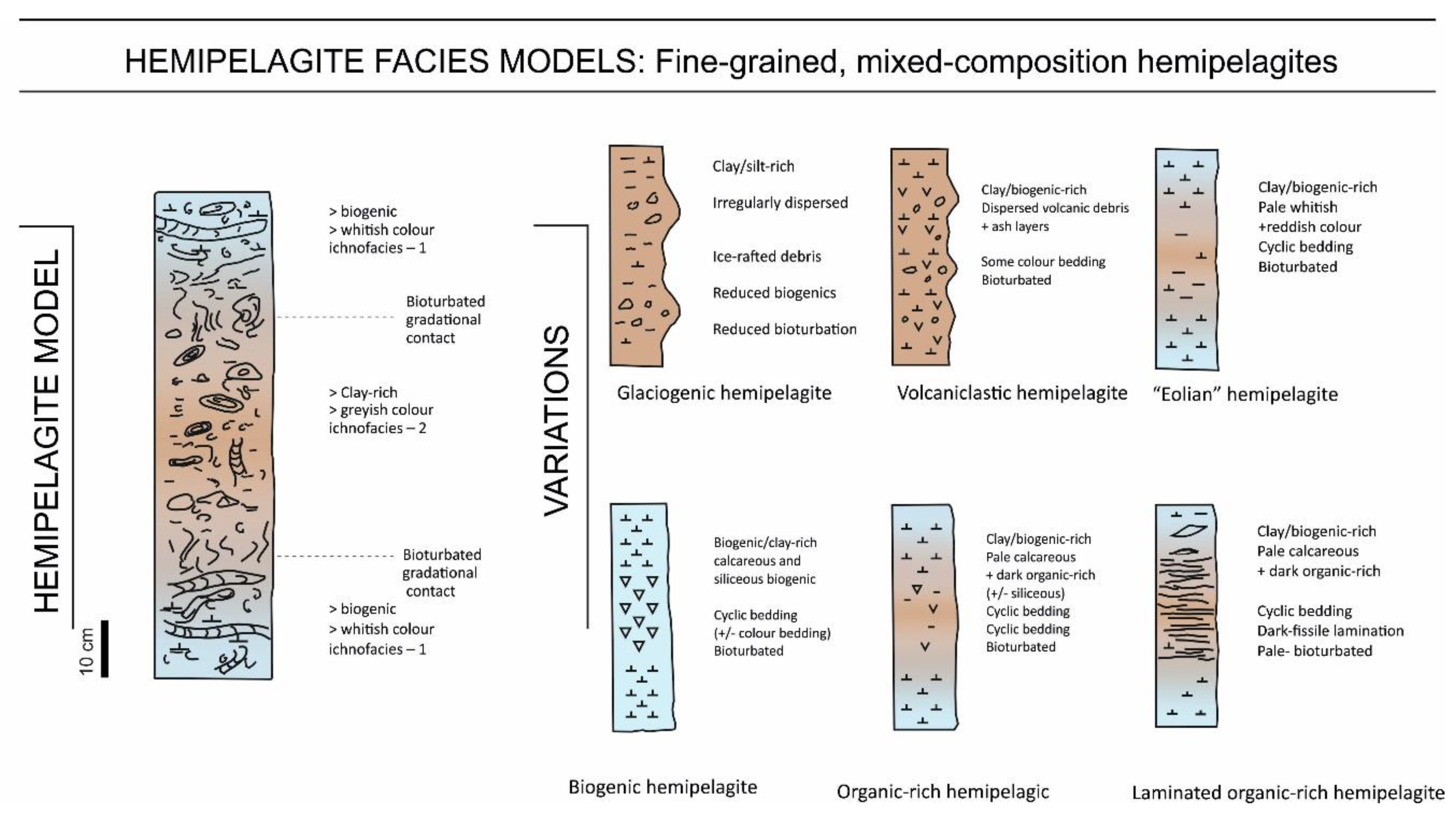
There have been, however, few attempts to develop a comprehensive facies model for hemipelagites [4,15,115]. A more recent refinement of the model elucidates the detailed facies characteristics and better represents the variety of hemipelagic facies that exist [70]. Further detailed observations of a typical hemipelagic succession offshore of SW Iberia are provided by [134]. The composite facies model shown in Figure 17, together with its several variations, has been compiled from this earlier work and represents the detailed characteristics outlined above.
Hemipelagites are fine-grained sediments, widespread over the shelf, slope and marginal basin settings. The standard facies model in Figure 17 shows indistinct bedding based on compositional (and colour) variation, with gradational contacts between beds due to extensive bioturbational mixing. Compaction, burial and diagenesis commonly accentuate such differences and yield a more well-bedded succession but retain the cyclicity in composition/colour. There are no primary sedimentary structures but a pervasive bioturbation with a high diversity of trace fossils in the Zoophycos-Nereites ichnofacies occurs. A tiered trace-fossil zonation is common where the rate of accumulation is more rapid. The mean size is fine (5–35 μm) and the sediment poorly sorted, with a bimodal to polymodal, mesokurtic to platykurtic distribution. The microfabric is random to semi-random. Composition is mixed biogenic and terrigenous, mostly supplied from the surface waters by vertical settling and slow lateral advection.
Variations from the standard model are also shown in Figure 17 and Figure 18. These illustrate some of the variability that exists due to compositional differences. Glacigenic hemipelagites at high latitudes are dominated by terrigenous material derived from ice rafting and by very poor sorting. Biogenic-rich hemipelagites are typical of low latitudes and upwelling zones, with little fluvial supply. Horizons with a reddish hue may indicate periods of time with a greater influx of wind-blown material (rich in iron-III). Volcaniclastic hemipelagites have an interspersed and poorly-sorted admixture of volcanic debris. Organic-rich hemipelagites have a darker grey–black colour and may display distinctive fissile lamination, with an absence of bioturbation where deposited under anoxic conditions. Cyclic variation of composition and colour is the norm for all types of hemipelagites, and is most commonly linked to climatic cyclicity.
6. Hybrid Deposits
Hybrid deposits (in deep-water) can be defined as those sediments showing characteristics intermediate between the deposits that are typical of other deep-water facies, namely, turbidites, contourites and hemipelagites. They result from process interaction, flow transformation and seafloor reworking of earlier deposits. A range of different types have been identified, but they are not necessarily easy to recognise from their mixed characteristics.
Hemiturbidites were first described from the distal Bengal Fan in the Indian Ocean [32], where they result from the progressive dilution and flow lofting of very low-concentration turbidity currents [33] and upward mixing into the overlying water column, leading to a process of mixed hemipelagic and turbiditic settling. The generally thick-bedded deposits are very fine-grained silty muds, with a mixed turbidite–hemipelagite composition and pervasive bioturbation throughout.
Hybrid event beds, as defined by [34], are the result of flow transformation within downslope gravity flows (or composite flows). These flows show an increase in concentration distally, meaning the high-concentration turbidity current transforms, in part, into a mudflow or debris flow. The resultant hybrid event bed typically shows a massive or laminated sandstone turbidite overlain by a debrite, as well as other hybrid variations [1,37]. A similar process of flow transformation was proposed by [72] to explain very thick-bedded structureless muds in distal basin-plain settings. In this case, a low-concentration turbidity current transforms into a highly-concentrated mudflow.
Bottom-current reworked pelagites and hemipelagites commonly occur where weak bottom currents interact with the background vertical settling processes in the open ocean, and gently winnow and rework the deposits. This may be evident from local winnowing and concentration of foraminiferal sands, regional variations in thickness, and/or widespread hiatuses. Reeder et al. [135] has interpreted the relatively high rates of hemipelagic accumulation in the Sicily gateway as the result of bottom-current lofting and re-suspension of the bottom-current load into the overlying water column. Marked thickness variations in mid-ocean pelagic successions, as noted by [136], can be interpreted as a weak bottom-current influence on an otherwise normal pelagite facies.
Bottom-current reworked turbidites have proved more difficult to identify with certainty. Some good modern examples have been described from the Columbia gateway in the SW Atlantic [137,138,139], the Tanzanian margin [140] and the Sicily gateway in the Mediterranean [135]. Some of the sediments described from mixed drift systems, such as those on the Antarctic Peninsula margin [141] and Tanzanian margin [140], have been interpreted as the result of sediment supply from turbidity currents, followed by the capture of the fine suspended cloud by active bottom currents. This material is then deposited at varying distances from the supply channel across the adjacent levees or mixed drift bodies in a down-current direction. They show clear, but somewhat irregular lamination coupled with bioturbation where lamination is less pronounced. Bulk grain-size analysis shows a very poorly sorted silty clay grain size, although individual silty laminae are no doubt slightly coarser grained. A mixed turbidite/contourite facies type seems reasonable.
We therefore recognise three different types of these hybrid turbidite–contourite beds that result from (a) short lateral diversion of a turbidity current by a bottom current (e.g., forming asymmetric levees), with little change to the fine-grained turbidite deposited; (b) longer-distance bottom-current transport of sediment captured from the top/tail of a turbidity current, yielding a deposit with turbidite composition and contourite characteristics (e.g., mixed drifts); and (c) reworking of the tops of already deposited turbidites by strong bottom currents, which can cause winnowing and cleaning of the turbidite sands, removal of the upper turbidite divisions or the superposition of contourite sands, muds and/or bioturbation.
7. Discussion
7.1. Controversy
The processes and facies characteristics of turbidites, contourites and hemipelagites, as outlined above, are each quite different from one another, much like apples and oranges! In theory, therefore, it should be relatively easy to distinguish between them. Turbidity currents are single, episodic events that result in a geologically instantaneous deposit (over minutes to days). For the most part, they are relatively high-energy, downslope currents capable of marked seafloor erosion as well as deposition. Bottom currents are continuous over long periods of time (over millions of years), with relatively slow accumulation of contourite deposits under low-energy alongslope currents, except where higher flow velocity causes a temporary hiatus or erosion. Hemipelagic settling is a continuous low-energy process that takes place in the absence of current activity, such that hemipelagites accumulate very slowly and continuously (over millions of years).
The facies models for the three sediment types, therefore, are distinct and different from each other, and, in many cases, it is quite easy to distinguish between them. However, this is not always so, such that a definitive interpretation may not be possible from the data available, especially when that data is only the small-scale observation of sediment facies and structures in a core or outcrop. It is strongly recommended here that purely speculative interpretations without sufficient evidence are not made. Difficulty and controversy arise for several reasons:
(1) The processes themselves show a degree of overlap as part of a process continuum, meaning the deposit characteristics also overlap as part of a facies continuum. This is particularly true for distinguishing between fine-grained turbidites and silty-muddy contourites, and also for distinguishing between muddy contourites and hemipelagites.
(2) The three facies types commonly occur closely interbedded in continental margin deposits. Episodic turbidites are blanketed by hemipelagites in some slope settings, and interbedded with contourites in other cases. Muddy contourites deposited by weak bottom currents are almost indistinguishable from interbedded hemipelagites.
(3) Strong bottom currents can winnow, erode and partially or completely rework turbidites. However, very similar erosion and reworking of turbidites can be caused by subsequent by-passing turbidity currents flowing over the pre-existing deposit. It is not easy to distinguish between these two events, especially where the composition of material moved or reworked by the different currents is the same.
(4) There is a significant amount of contradictory information in the literature. Some authors claim that traction structures are widespread in all contourites, as though tractional movement of sediment were the preserve of bottom currents (e.g., [6,142]). In fact, neither contention is true. Primary structures are either not present or largely destroyed by bioturbation in finer-grained contourites, whereas they may be preserved in sandy contourites. The lamination and cross-lamination in turbidites is also the result of bedload traction. The simplistic diagrams showing sedimentary structures interpreted as diagnostic of contourites (e.g., [6,142,143]) are very misleading, as all the structures depicted can equally be generated by turbidity currents and many by other processes as well.
(5) Individual sedimentary characteristics, such as parallel lamination, cross-bedding and structureless muds/sands, can occur in almost every environment. Even combinations of several features are not definitive. Heterolithic facies with silt/sand laminae and micro-cross-lamination with interlaminated mud (e.g., fading ripples) are typical of fine-grained turbidites, but similar facies are also common in tidal and deltaic settings. Dune cross-bedded sands may be typical of some sandy contourites, and only rare in turbidites, but they are also common on the floors of turbidity current channels, in estuarine and other shallow-water nearshore and shelf deposits and in fluvial and eolian environments.
However, as evidenced in this paper, much progress has been made over the past decade in distinguishing between end-member facies in terms of their sedimentary structures, facies sequences, ichnofacies, sediment textures, composition and microfabric. However, equally, it must be acknowledged that clear distinction is not always possible on the basis of sedimentary characteristics alone. In any particular study, the only scientifically valid method to follow, in the absence of definitive evidence, is not to make a single interpretation but to acknowledge and highlight any uncertainties.
7.2. Comparing Apples and Oranges
The wide range of facies types within each of the main groups (turbidites, contourites and hemipelagites) is not always fully recognised. Coarse-, medium- and fine-grained turbidites are completely different from one another; for example, a 2 m thick structureless sand and a 2 mm thick wispy silt lamina may both be turbidites, the one very proximal and the other very distal. Taking our apples and oranges metaphor (above), it is tempting to assume that these two facies must be from altogether different groups, i.e., turbidites (apples) and contourites (oranges). In fact, they are simply different types of turbidites (apples).
We suggest that this error is very often made when attempting to interpret ancient successions on the basis of the appearance of sediment facies or sedimentary structures alone. Very many fine-grained turbidites have been erroneously interpreted as contourites, as carefully documented in [27,28,92,100]. The problems of misinterpretation continue, however, to be exacerbated by the contradictory information in the literature, as highlighted above. Most of the sedimentary structures attributed to contourites by [143,144], especially those depicting thin and very thin beds, are almost certainly due to fine-grained turbidites in our view. We see ample evidence for these structures in turbidite systems (see above), but very few recorded from present-day contourite drifts.
A further complication arises in determining the depositional process for medium- and thick-bedded sandy facies in deep-water. Parallel-lamination is the norm for turbidite beds with Bouma B-division structures; ripple cross-lamination is typical of Bouma C-division turbidites; and dune-cross bedding is common for by-pass turbidites on channel floors. However, all these structures are now known to occur in sandy contourites [105]. In this case, the apples (turbidites) and oranges (contourites) may actually appear almost identical in their sedimentary characteristics. Guessing an interpretation on the basis of these data alone is not valid. Other criteria must be used where available.
The Miocene sand-rich succession in the Rifean Corridor, Morocco, with extensive parallel and cross-bedding, was interpreted to be of contourite origin on the basis of careful geological scrutiny and multiple criteria [145]. These included unidirectional cross-bedding and bioturbation, microfossil evidence for deposition at a water depth of 150–300 m, associated facies with bi-gradational sequences typical of mixed contourites, location of the sandstone bodies within a narrow former oceanic gateway between the Atlantic Ocean and Mediterranean Sea, the elongation of these bodies along the length of the gateway and the association of the bodies with several regional hiatuses in the sedimentary record, as well as elongate mounded drifts and moats identified in seismic profiles at the western mouth of the gateway. The authors further concluded that the Rifean Corridor bottom current may have been modulated by a strong deep tidal component.
This interpretation is an example of applying multiple criteria and a three-scale approach, as discussed below.
7.3. Three Scales of Interpretation
Whereas most turbidites or debrites can be readily identified as such even with cursory field examination, there are others that are so easily designated. Thick structureless sands, parallel-laminated sands and ripple-laminated sands, for example, are found in almost every depositional environment from fluvial to deltaic and from coastal to deep marine. Structureless and bioturbated muds are also commonplace. It is still notoriously difficult to recognize contourite deposits and the influence of bottom currents in ancient successions, and even more so to recognise where a turbidite has been modified by a bottom current or where internal tides and waves have affected the seafloor sediment [143]. There are several simplified schemes published that purport to provide diagnostic criteria for recognizing and differentiating between different deep-water facies (e.g., [60,61,142]. However, careful scrutiny shows them to be wanting and inconclusive [27,29,57,100].
A logical and scientifically valid three-scale approach is now well accepted by many deep-water specialists for the field identification of ancient contourites [87,91,99,138,139,145,146]. We here propose that this same approach should be followed wherever possible for all three types of deep-water facies, and have therefore modified and extended the set of criteria to be fulfilled and questions answered, as presented below. This method clearly acknowledges the need to consider all evidence at the small scale (in the field, borehole and through laboratory analysis); at the medium scale (depositional body, formation and region); and at the large scale (sedimentary system, oceanographic and tectonic setting). A similar three-scale approach has also been established for assessing seismic criteria in the recognition of contourite systems [141,147,148].
A sequential workflow procedure is suggested below, working from the small to medium to large scale. Of course, it is equally valid to work the other way round, from the large scale to the small scale, or to make observations concurrently. Equally, it is not always possible to consider all attribute types and at all scales of observation, but the more that are available for scrutiny, then the more reliable the interpretation will become.
7.3.1. Small Scale (Field, Borehole and Laboratory Analysis)
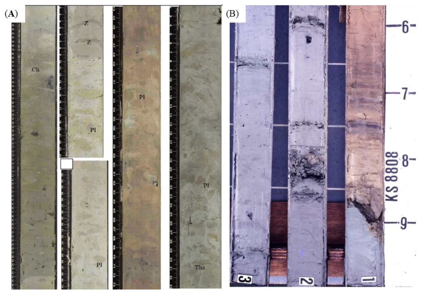
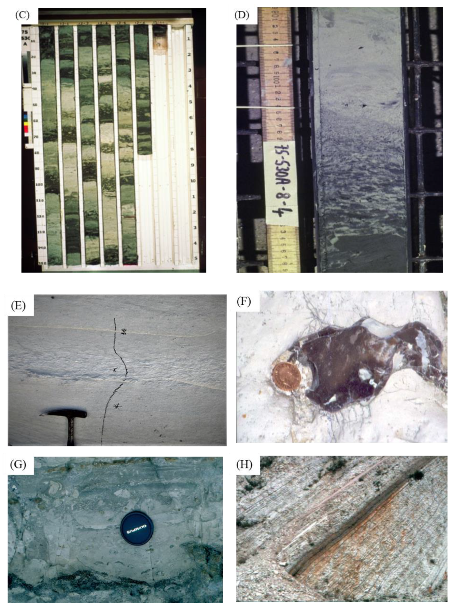
1. Do the sediments have the range of features as described in the text above (Section 3, Section 4 and Section 5) and illustrated in the facies photographs (Figure 7, Figure 9, Figure 12, Figure 15, Figure 16 and Figure 18) that are typical of turbidites, contourites or hemipelagites? This necessitates observation of a combination of features, rather than a single attribute, and also multiple observations of a particular characteristic, rather than only one or two examples. More specifically:
(a) Sedimentary structures: An assemblage of structures, rather than single structures, is required for more definitive diagnosis, especially the presence of a sequence of structures that match those of the idealised facies models and their variation as partial sequences. Note that structures such as ripple cross-lamination are formed by tractional grain movement at the base of many flow types—turbidity currents, bottom currents, and deep tidal currents, for example.
(b) Textures: These are very variable for all three facies types. Single observations of textural parameters (mean size, sorting and skewness, etc.) are not, therefore, adequate. Multiple analyses are required. Good progress is being made in characterising different facies types through bi-variate cross plots of textural attributes—e.g., mean-size versus sorting, sorting versus skewness, the coarsest one-percentile (C) versus median (M) (CM plots) [105,149]. Distinguishing between facies in this way seems to be better for silt to medium sand grades, but is more equivocal for both finer and coarser grain sizes.
(c) Grading: This is an important distinguishing feature, where present. Many turbidites show normal grading or graded laminated beds but others do not. In ancient turbidites in particular, the sand and mud divisions of single beds have a sharp grain-size break rather than a gradational contact. Many contourites show bi-gradational sequences (i.e., reverse to normal grading), but others, especially many sandy contourites, do not. Hemipelagites show no systematic grading.
(d) Composition: There are no easy general rules for distinguishing facies on the basis of composition alone. This depends principally on the nature of the source and supply of material, which can vary widely within and between the different facies. Where there are marked differences in composition between beds or facies within a single succession, this then should be investigated in terms of potentially different processes and supply routes.
(e) Bioturbation and trace fossils: Turbidites generally show intermittent episodes of bioturbation in between events; the bioturbation penetrates from the top of a turbidite bed downwards. Contourites (especially finer-grained facies) show persistent and pervasive bioturbation throughout more or less continuous sedimentation; there may be omission surfaces and/or a more restricted ichnofacies. Sandy contourites (especially coarser-grained ones) show less bioturbation. Hemipelagites generally show pervasive, tiered and diverse bioturbation and ichnofacies assemblages. Dysoxic to anoxic bottom water conditions will restrict or prevent bioturbation of all deep-water facies.
2. Are there any clear paleocurrent measurements available that indicate a predominantly alongslope or downslope flow direction? Hemipelagites show no evidence of current activity. However, it must be noted that interpretation of paleocurrent evidence is fraught with difficulties. Turbidites can show very variable patterns due to flow instability and reflection, channel meandering, flow-stripping across levees and Coriolis deflection. Sandy contourites within contourite channels are also known to show variable directions due to channel margin interference and interaction with other processes such as deep tidal currents, and with mesoscale and macroscale eddies. It is therefore essential to obtain multiple measurements rather than simply a few, and to establish general flow trends. Especially where different facies are interbedded, they may show differences in dominant flow direction.
3. Where there is a possibility of interbedded turbidite/contourite sequences, can a distinction be made between the two facies present on the basis of character, composition and/or paleocurrent evidence? Where there is a possibility of mixed hemipelagite–pelagite/contourite/turbidite sequences, is there sufficient evidence for the influence of bottom currents or turbidity currents during sedimentation? Note that interbedding of different facies types is likely to be the norm on many continental margins, meaning this facies pattern should be specifically examined.
4. Can any cyclicity present be clearly related to long-term variation in bottom-current velocity or sediment supply, or to short-term terrigenous sediment input or biogenic productivity? Can the nature and duration of such cyclicity be precisely identified through biostratigraphical chronology, magnetostratigraphy, or by tuning to the astronomical time-scale?
5. Is there sufficient combined evidence to allow a most-likely interpretation at this stage? In many cases, this will not be possible, and it is therefore important not to force an interpretation that has a high degree of uncertainty. Several options can be presented and either probability or uncertainty factors noted. Particular care must be taken for inferred reworked turbidites, for which we currently lack definitive criteria, and also for indistinct muddy contourites, which are not easily differentiated from hemipelagites.
At this stage, further observations and/or analytical work may be required as well as interrogation of the evidence from medium- and large-scale observations.
7.3.2. Medium Scale (Depositional Body, Formation or Region)
1. Do regional trends in facies occurrence, paleocurrent directions, textures, and mineralogical or geochemical tracers exist that would support (a) a generally alongslope bottom-current origin; (b) a downslope turbidity-current supply route; or (c) vertical settling in the absence of current activity? This can best be interrogated on the basis of careful regional mapping in the field, data from multiple boreholes in the subsurface and high-resolution seismic data where available. Laboratory analyses from this wide dataset will need to be collated.
2. Is there any evidence of (a) bottom-current activity, such as widespread unconformities, condensed sequences, regional variation in thickness (allowing reconstruction of mound-like geometry) and drift geometry; (b) turbidity current activity, such as localised channel erosion, abundant shale clasts and associated mass-transport deposits; or (c) a complete absence of anything other than slow continuous and pervasive hemipelagic sedimentation? This requires a similar approach to that for (1) above. In addition, biostratigraphic data is needed, for example, from micropaleontological analyses.
3. Is it possible to reconstruct the shape and 3D geometry of the whole sedimentary body? If so, are the elongation and propagation trends parallel or perpendicular to the inferred margin? Or is the geometry a widespread drape over underlying topography? Both surface mapping and subsurface seismic data will be required to answer these questions.
4. Are the associated facies, paleontological data and rates of accumulation compatible with a deep-water depositional setting interpretation? It is important to interrogate and confirm the depositional setting and to consider facies associations and medium-scale vertical sequences of facies or bed thicknesses. Even where it is difficult to gather evidence from putative turbidites or contourites, it may be easier to observe that the interbedded associated facies are dominantly of deep-water pelagic and hemipelagic type. Vertical trends of turbidite bed thickness have been extensively studied and documented, so that thinning-up, thickening-up, and compensation cycles can be recognised. Regular cyclicity with orbital periodicity is well known for hemipelagite–pelagite successions. Work is currently ongoing with regard to bed thickness and cyclicity variation in contourites, but the need for precise chronology is paramount.
5. Is there any seismic evidence for depositional setting and style? Consider, in particular, the small- and medium-scale seismic criteria listed by [141,148], such as seismic facies, architectural elements and progradational/aggradational patterns. However, it is important to note that features such as giant sediment waves (1–3 km wavelength) (typical as a recognised seismic facies) may be formed as the result of both bottom current and turbidity current activity [150]. Their link to downslope creep processes (perhaps of hemipelagic sediments) is less well established.
7.3.3. Large Scale (System, Ocean or Continent)
1. Do the conclusions from Stages 1 and 2 above fit with what is known from other independent lines of evidence concerning major oceanographic or paleoceanographic features and continental reconstructions? Are bottom currents or turbidity currents to be expected in the depositional setting reconstructed, and are interbedded facies to be expected?
2. What kind of bottom-current systems might have existed in the study area at the time of deposition, taking into account constraints imposed by known paleoclimatic conditions and inferred basin location and geometry?
3. Was there an obvious sediment source and downslope supply route for turbidity currents?
4. Is there any independent seismic evidence for the oceanographic setting, shelf-slope geometry and potential water depth at the time of deposition? Consider, in particular, the large- and medium-scale seismic criteria listed by [114].
8. Conclusions
Significant progress has been made in the last two decades in distinguishing between turbidites, contourites and hemipelagites in modern and ancient deep-water systems. However, there is still much controversy surrounding classification, especially where the interpretation of ancient series is concerned. There are four main reasons for this: (1) the transport-depositional processes show a degree of overlap as part of a continuum, meaning the deposit characteristics also overlap; (2) the three facies commonly occur interbedded within continental margin deposits, meaning interpretation based on occurrence is not always possible; (3) there are many published examples of speculative interpretations of ancient sediments where the evidence is limited (e.g., sedimentary structures alone) and the conclusions erroneous; and (4) several sets of conflicting criteria for facies interpretation exist in the literature, especially for contourites but also for sandy turbidites and debrites.
There is good agreement now on the nature of the end-member processes and their physical parameters.
- Turbidity currents are episodic short-duration events (lasting hours to days) which show wide variation in flow size, speed and concentration. They are turbulent suspensions of mud and sand in water which are propelled downslope by gravity acting on the excess density. They can develop internal segregation in terms of process and sediment concentration, as well as downslope flow transformation.
- Bottom currents are semi-continuous long-duration processes (lasting thousands to millions of years) which are generally low-concentration and which have a relatively low flow speed. They can be driven by surface winds, thermohaline circulation and tides. They are affected by intermittent eddies, benthic storms, flow cascading and tsunamis.
- Hemipelagic deposition is a continuous process through geological time, involving both vertical settling and slow lateral advection through the water column. Together with pelagic settling, these are ‘background’ processes which are only evident in the absence of either turbidity currents or bottom currents.
These end-member processes lead to deposits that are characterised by specific sedimentary features, including sedimentary structures, facies sequences, ichnofacies, sediment textures, composition and microfabric. These characteristics are best summarised in terms of standard facies models or sequences and the variations from these models that are typically encountered in natural systems. We have synthesised data on the principal facies models and illustrated each type with photographs of modern and ancient examples from well-established systems.
- Turbidites, including coarse-, medium-, and fine-grained turbidites, characterised by the Lowe, Bouma and Stow sequences respectively. We note that it is not always possible to distinguish between facies at the fine end of the spectrum, i.e., muddy turbidites, contourites and hemipelagites. Equally, some of the sand-only turbidites and contourites may show very similar features.
- Contourites, including bi-gradational mud–sand and sandy contourite facies models. The bi-gradational sequence (C1–C5) is well established, whereas the sandy contourite models are relatively new. Contourites are much less well known than turbidites from ancient series on land or in the subsurface. This is an important area for future research.
- Hemipelagites have a simple cyclic facies model, showing compositional and colour variation. There is a wide range of types depending on dominant sediment supply, i.e., biogenic, terrigenous, volcaniclastic and glacigenic. Organic-rich black-shale hemipelagites have different and specific characteristics.
It must be recognised that clear distinction is not always possible on the basis of sedimentary characteristics alone, and that uncertainties should be highlighted in any interpretation. It is far better to declare a lack of sufficient evidence than to make a speculative interpretation that may be misleading to subsequent workers. Wherever possible, a three-scale approach to distinction for all deep-water facies types should be attempted, including large-scale (oceanographic and tectonic setting), regional-scale (architecture and association), and small-scale (sediment facies) observations. It is only by using this rigorous scientific method that a valid outcome can be achieved.
The authors are aware of further work that is currently in progress on microfacies characterisation of deep-water carbonates, microfabric discrimination of fine-grained clastic facies, textural discrimination of turbidites and contourites and the distinctive nature of facies cyclicity and meso-scale sequences (5–50 m). All of these approaches are expected to yield important data and results for this ongoing debate. Future approaches to the deep-water sedimentary systems that we believe will be especially significant include (a) direct long-term seafloor observations, measurement and sampling; (b) establishing a sound evidential link between the process of deposition and nature of the deposit; (c) resolving the nature and effects of process interaction; and (d) working towards a clearer understanding of the broader societal impact of our deep-sea research. Finally, we should always read published work (including this paper) with a critical mind.
Author Contributions
This paper is a wide-ranging review compilation. It is based on many years of work by D.S., and, more recently, by Z.S. on the topic of contourites. The original draft was written by D.S. and then modified after discussion with Z.S. The figures have been jointly compiled and drafted. All authors have read and agreed to the published version of the manuscript.
Funding
The compilation of this review paper received no specific external funding. However, the data and ideas were collected over many years and were the result of a wide range of funding.
Acknowledgments
Huge thanks are due, in particular, to the very many students and colleagues who have contributed to our deep-water research efforts over the years, on land, at sea and in subsurface cores. The manuscript has benefited much from the input of several careful and detailed reviewers.
Conflicts of Interest
The authors declare no conflict of interest. The funders had no role in the design of the study; in the collection, analyses, or interpretation of data; in the writing of the manuscript; or in the decision to publish the results.
References
- Pickering, K.; Hiscott, R. Deep Marine Systems: Processes, Deposits, Environments, Tectonics and Sedimentation; Wiley & American Geophysical Union: Washington, DC, USA, 2016. [Google Scholar]
- Huneke, H.; Mulder, T. Deep-Sea Sediments; Elsevier: Amsterdam, The Netherlands, 2011. [Google Scholar]
- Rebesco, M.; Camerlenghi, A. Contourites; Elsevier: Amsterdam, The Netherlands, 2008; Volume 60, pp. 457–489. [Google Scholar]
- Stow, D.A.V. Fine-grained sediments in deep water: An overview of processes and facies models. Geo-Mar. Lett. 1985, 5, 17–23. [Google Scholar] [CrossRef]
- Shanmugam, G. 50 years of the turbidite paradigm (1950s—1990s): Deep-water processes and facies models—A critical perspective. Mar. Pet. Geol. 2000, 17, 285–342. [Google Scholar] [CrossRef]
- Shanmugam, G. Deep-water bottom currents and their deposits. In Developments in Sedimentology; Elsevier BV: Amsterdam, The Netherlands, 2008; Volume 60, pp. 59–81. [Google Scholar]
- Rebesco, M.; Camerlenghi, A.; Van Loon, A.J. Contourite research. In Developments in Sedimentology; Elsevier BV: Amsterdam, The Netherlands, 2008; Volume 60, pp. 1–10. [Google Scholar]
- Murray, S.J.; Renard, A.F. Report on Deep-sea Deposits Based on the Specimens Collected During the Voyage of H.M.S. Challenger in the Years 1872 to 1876; H.M. Stationery Office: Richmond, UK, 1891.
- Murray, J.; Hjort, J. The Depths of the Ocean; A General Account of the Modern Science of Oceanography Based Largely on the Scientific Researches of the Norwegian Steamer Michael Sars in the North Atlantic; Smithsonian Institution, Macmillan and Co.: Lonodon, UK, 1912. [Google Scholar]
- Jenkyns, H.C.; Clayton, C.J. Black shales and carbon isotopes in pelagic sediments from the Tethyan Lower Jurassic. Sedimentology 1986, 33, 87–106. [Google Scholar] [CrossRef]
- Kuenen, P.H.; Migliorini, C.I. Turbidity Currents as a Cause of Graded Bedding. J. Geol. 1950, 58, 91–127. [Google Scholar] [CrossRef]
- Bouma, A.H. Sedimentology of Some Flysch Deposits; A Graphic Approach to Facies Interpretation; Elsevier: Amsterdam, The Netherlands, 1962. [Google Scholar]
- Mutti, E. Turbidite Sandstones. Milan; Agip, Istituto di geologia, Università di Parma: Parma, Italy, 1992. [Google Scholar]
- Ghibaudo, G. Subaqueous sediment gravity flow deposits: practical criteria for their field description and classification. Sedimentology 1992, 39, 423–454. [Google Scholar] [CrossRef]
- Stow, D.A.V. Deep clastic seas. In Sedimentary Environments and Facies; Reading, H.G., Ed.; Blackwell: Oxford, UK, 1986; pp. 339–444. [Google Scholar]
- Stow, D.A.V. Deep sea processes of sediment transport and deposition. In Sediment Transport and Depositional Processes; Pye, K., Ed.; Blackwell: Oxford, UK, 1994; pp. 257–291. [Google Scholar]
- Stow, D.A.V.; Reading, H.G.; Collinson, J. Deep seas. In Sedimentary Environments and Facies, 3rd ed.; Reading, H.G., Ed.; Blackwell: Oxford, UK, 1996; pp. 380–442. [Google Scholar]
- Pickering, K.T.; Clark, J.D.; Smith, R.D.A.; Hiscott, R.N.; Lucchi, F.R.; Kenyon, N.H. Architectural element analysis of turbidite systems, and selected topical problems for sand-prone deep-water systems. In Atlas of Deep Water Environments; Springer Science and Business Media LLC: Berlin/Heidelberg, Germany, 1995; pp. 1–10. [Google Scholar]
- Mulder, T.; Cochon, P. Classification of offshore mass movements. J. Sediment. Res. 1996, 66, 43–57. [Google Scholar]
- Heezen, B.C.; Hollister, C.D.; Ruddiman, W.F. Shaping of the continental rise by deep geostrophic contour currents. Science 1966, 152, 502–508. [Google Scholar] [CrossRef] [PubMed]
- Stow, D.A.V. Late Quaternary Stratigraphy and Sedimentation on the Nova Scotian Outer Continental Margin. Unpublished Ph.D. Thesis, Dalhousie University, Halifax, NS, Canada, 1977; p. 360. [Google Scholar]
- Stow, D.A.V. Distinguishing between fine-grained turbidites and contourites on the Nova Scotian deep water margin. Sedimentology 1979, 26, 371–387. [Google Scholar] [CrossRef]
- Hollister, C.D.; Heezen, B.C. Geological effects of ocean bottom currents: Western North Atlantic. In Studies in Physical Oceanography; Gordon, A.L., Ed.; Gordon and Breach: New York, NY, USA, 1972; Volume 2, pp. 37–66. [Google Scholar]
- McCave, I.N.; Tucholke, B.E. Deep current-controlled sedimentation in the western North Atlantic. In The Western North Atlantic Region; Geological Society of America: Boulder, CO, USA, 1986; pp. 451–468. [Google Scholar]
- Stow, D.A.; Mayall, M. Deep-water sedimentary systems: New models for the 21st century. Mar. Pet. Geol. 2000, 17, 125–135. [Google Scholar] [CrossRef]
- Stow, D.A.V.; Omoniyi, B. Thin-bedded turbidites: Overview and petroleum perspective. In Rift-related coarse-Grained Submarine Fan Reservoirs; the Brae Play, South Viking Graben, North Sea; Turner, C.C., Cronin, B.T., Eds.; American Association of Petroleum Geologists: Tulsa, OK, USA, 2018; Volume 115, pp. 257–282. [Google Scholar]
- Stow, D.A.V.; Faugères, J.-C. Contourite facies and the facies model. In Developments in Sedimentology; Elsevier BV: Amsterdam, The Netherlands, 2008; Volume 60, pp. 223–256. [Google Scholar]
- Stow, D.A.V.; Faugères, J.-C.; Howe, J.A.; Pudsey, C.J.; Viana, A.R. Bottom currents, contourites and deep-sea sediment drifts: Current state-of-the-art. Geol. Soc. Lond. Memoirs 2002, 22, 7–20. [Google Scholar] [CrossRef]
- Stow, D.; Smillie, Z.; Esentia, I. Deep-Sea bottom currents: Their nature and distribution. In Encyclopedia of Ocean Sciences; Elsevier BV: Amsterdam, The Netherlands, 2018. [Google Scholar]
- Stow, D.; Smillie, Z.; Pan, J.; Esentia, I. Deep-Sea contourites: Sediments and cycles. In Encyclopedia of Ocean Sciences; Elsevier BV: Amsterdam, The Netherlands, 2019; pp. 111–120. [Google Scholar]
- Bankole, S.A.; Buckman, J.; Stow, D.; Lever, H. Automated image analysis of mud and mudrock microstructure and characteristics of hemipelagic sediments: IODP expedition 339. J. Earth Sci. 2019, 30, 407–421. [Google Scholar] [CrossRef]
- Stow, D.A.V.; Wetzel, A. Hemiturbidite: A new type of deep water sediment. Proc. ODP Sci. Results 1990, 116, 25–34. [Google Scholar]
- Sparks, R.S.J.; Bonnecaze, R.T.; Huppert, H.E.; Lister, J.R.; Hallworth, M.A.; Mader, H.; Phillips, J. Sediment-laden gravity currents with reversing buoyancy. Earth Planet. Sci. Lett. 1993, 114, 243–257. [Google Scholar] [CrossRef]
- Haughton, P.; Davis, C.; McCaffrey, W.; Barker, S. Hybrid sediment gravity flow deposits – Classification, origin and significance. Mar. Pet. Geol. 2009, 26, 1900–1918. [Google Scholar] [CrossRef]
- Talling, P.J.; Paull, C.K.; Piper, D.J. How are subaqueous sediment density flows triggered, what is their internal structure and how does it evolve? Direct observations from monitoring of active flows. Earth-Sci. Rev. 2013, 125, 244–287. [Google Scholar] [CrossRef] [Green Version]
- Strachan, L.J.; Bostock, H.C.; Barnes, P.M.; Neil, H.L.; Gosling, M. Non-cohesive silt turbidity current flow processes; insights from proximal sandy-silt and silty-sand turbidites, Fiordland, New Zealand. Sediment. Geol. 2016, 342, 118–132. [Google Scholar] [CrossRef]
- Bonzetti, G.; Cronin, B.T.; Jones, M.A. Deepwater conglomeratic megabeds: Analogues for event beds of the Brae Formation, S Viking Graben, North Sea. In Rift-Related Coarse-Grained Submarine Fan Reservoirs; The Brae Play, South Viking Graben, North Sea; Turner, C.C., Cronin, B.T., Eds.; American Association of Petroleum Geologists: Tulsa, OK, USA, 2018; Volume 115. [Google Scholar]
- Bagnold, R.A. Auto-suspension of transported sediment; turbidity currents. Proc. R. Soc. Lond. Ser. A Math. Phys. Sci. 1962, 265, 315–319. [Google Scholar]
- Mulder, T.; Migeon, S.; Savoye, B.; Faugeres, J.-C. Inversely graded turbidite sequences in the deep Mediterranean: a record of deposits from flood-generated turbidity currents? Geo-Mar. Lett. 2001, 21, 86–93. [Google Scholar]
- Mulder, T.; Syvitski, J.P.; Migeon, S.; Faugeres, J.-C.; Savoye, B. Marine hyperpycnal flows: Initiation, behavior and related deposits. A review. Mar. Pet. Geol. 2003, 20, 861–882. [Google Scholar] [CrossRef]
- Sequeiros, O.E.; Naruse, H.; Endo, N.; García, M.H.; Parker, G. Experimental study on self-accelerating turbidity currents. J. Geophys. Res. Space Phys. 2009, 114. [Google Scholar] [CrossRef]
- Baker, M.L.; Baas, J.H.; Malarkey, J.; Jacinto, R.S.; Craig, M.J.; Kane, I.A.; Barker, S. The effect of clay type on the properties of cohesive sediment gravity flows and their deposits. J. Sediment. Res. 2017, 87, 1176–1195. [Google Scholar] [CrossRef] [Green Version]
- Paull, C.K.; Talling, P.J.; Maier, K.L.; Parsons, D.; Xu, J.; Caress, D.W.; Gwiazda, R.; Lundsten, E.M.; Anderson, K.; Barry, J.P.; et al. Powerful turbidity currents driven by dense basal layers. Nat. Commun. 2018, 9, 4114. [Google Scholar] [CrossRef] [PubMed] [Green Version]
- Maier, K.L.; Gales, J.A.; Paull, C.K.; Rosenberger, K.; Talling, P.J.; Simmons, S.M.; Gwiazda, R.; McGann, M.; Cartigny, M.J.B.; Lundsten, E.; et al. Linking direct measurements of turbidity currents to submarine canyon-floor deposits. Front. Earth Sci. 2019, 7, 144. [Google Scholar] [CrossRef]
- Symons, W.O.; Sumner, E.J.; Paull, C.K.; Cartigny, M.J.; Xu, J.; Maier, K.L.; Lorenson, T.D.; Talling, P.J. A new model for turbidity current behavior based on integration of flow monitoring and precision coring in a submarine canyon. Geology 2017, 45, 367–370. [Google Scholar] [CrossRef] [Green Version]
- Clare, M.A.; Le Bas, T.; Price, D.M.; Hunt, J.E.; Sear, D.; Cartigny, M.J.B.; Vellinga, A.; Symons, W.; Firth, C.; Cronin, S. Complex and cascading triggering of submarine landslides and turbidity currents at volcanic islands revealed from integration of high-resolution onshore and offshore surveys. Front. Earth Sci. 2018, 6, 223. [Google Scholar] [CrossRef]
- Meiburg, E.; Nasr-Azadani, M.M. Gravity and Turbidity Currents: Numerical Simulations and Theoretical Models’, in Mixing and Dispersion in Flows Dominated by Rotation and Buoyancy; Clercx, H.J.H., Van Heijst, G.F., Eds.; Springer International Publishing AG: Cham, Switzerland, 2018; pp. 129–180. [Google Scholar]
- Lai, Y.G.; Huang, J.C.; Wu, K.W. Reservoir turbidity current modeling with a two-dimensional layer-averaged model. J. Hydraul. Eng. 2015, 141, 04015029. [Google Scholar] [CrossRef]
- Sansom, P. Turbidites v Contourites: hybrid systems of the Tanzanian margin. In Proceedings of the PESGB/HGS African Conference, London, UK, 31 August–1 September 2017. [Google Scholar]
- Lowe, N.R. Subaqueous liquefied and fluidized sediment flows and their deposits. Sedimentology 1976, 23, 285–308. [Google Scholar] [CrossRef]
- Varnes, D.J. Slope Movement Types and Processes. In Landslides, Analysis and Control, Transportation Research Board, Special Report No. 176; National Academy of Sciences: Washington, DC, USA, 1978; pp. 11–33. [Google Scholar]
- Stow, D.A.V.; Bowen, A.J. A physical model for the transport and sorting of fine-grained sediment by turbidity currents. Sedimentology 1980, 27, 31–46. [Google Scholar] [CrossRef]
- Bowen, A.J.; Normark, W.R.; Piper, D.J.W. Modelling of turbidity currents on Navy Submarine Fan, California Continental Borderland. Sedimentology 1984, 31, 169–185. [Google Scholar] [CrossRef]
- Komar, P.D. The hydraulic interpretation of turbidites from their grain sizes and sedimentary structures. Sedimentology 1985, 32, 395–407. [Google Scholar] [CrossRef]
- Piper, D.J.W.; Stow, D.A.V. Fine-grained turbidites. In Cycles and Events in Stratigraphy; Einsele, G., Ricken, W., Seilacher, A., Eds.; Springer-Verlag: Berlin/Heidelberg, Germany, 1991; pp. 360–376. [Google Scholar]
- Pantin, H.M.; Leeder, M.R. Reverse flow in turbidity currents: The role of internal solitons. Sedimentology 1987, 34, 1143–1155. [Google Scholar] [CrossRef]
- Rebesco, M.; Hernández-Molina, F.J.; Van Rooij, D.; Wahlin, A. Contourites and associated sediments controlled by deep-water circulation processes: State-of-the-art and future considerations. Mar. Geol. 2014, 352, 111–154. [Google Scholar] [CrossRef] [Green Version]
- Esentia, I.; Stow, D.; Smillie, Z. Contourite drifts and associated bedforms. In Submarine Geomorphology; Springer: Cham, Switzerland, 2018; pp. 301–331. [Google Scholar]
- Ma, X.; Yan, J.; Hou, Y.; Lin, F.; Zheng, X. Footprints of obliquely incident internal solitary waves and internal tides near the shelf break in the northern South China Sea. J. Geophys. Res. Oceans 2016, 121, 8706–8719. [Google Scholar] [CrossRef] [Green Version]
- Shanmugam, G. Deep-water bottom currents. In Handbook of Petroleum Exploration and Production; Elsevier: Amsterdam, The Netherlands, 2006; Volume 5, pp. 85–139. [Google Scholar]
- Shanmugam, G. New Perspectives on Deep-Water Sandstones Origin, Recognition, Initiation and Reservoir Quality, 1st ed.; Elsevier: Amsterdam, The Netherlands, 2012. [Google Scholar]
- McCave, I. Size sorting during transport and deposition of fine sediments. In Developments in Sedimentology; Elsevier BV: Amsterdam, The Netherlands, 2008; Volume 60, pp. 121–142. [Google Scholar]
- Stow, D.A.V.; Hunter, S.; Wilkinson, D.; Hernández-Molina, F.J. The nature of contourite deposition. In Contourites; Rebesco, M., Camerlenghi, A., Eds.; Elsevier: Amsterdam, The Netherlands, 2008; Volume 60, pp. 143–156. [Google Scholar]
- Zenk, W. Abyssal and contour currents. In Developments in Sedimentology; Elsevier BV: Amsterdam, The Netherlands, 2008; Volume 60, pp. 35–57. [Google Scholar]
- Rebesco, M.; Taviani, M. 4 A turbulent story: Mediterranean contourites and cold-water corals. In Mediterranean Cold-Water Corals: Past, Present and Future: Understanding the Deep-Sea Realms of Coral; Orejas, C., Jiménez, C., Eds.; Springer International Publishing: Cham, Switzerland, 2019; pp. 35–46. [Google Scholar]
- Huneke, H.; Stow, D. Identification of ancient contourites: problems and palaeoceanographic significance. In Developments in Sedimentology; Elsevier BV: Amsterdam, The Netherlands, 2008; Volume 60, pp. 323–344. [Google Scholar]
- Lofi, J.; Voelker, A.H.L.; Ducassou, E.; Hernández-Molina, F.J.; Sierro, F.J.; Bahr, A.; Galvani, A.; Lourens, L.J.; Pardo-Igúzquiza, E.; Pezard, P.; et al. Quaternary chronostratigraphic framework and sedimentary processes for the Gulf of Cadiz and Portuguese Contourite Depositional Systems derived from Natural Gamma Ray records. Mar. Geol. 2016, 377, 40–57. [Google Scholar] [CrossRef]
- Stow, D.; Hernández-Molina, F.; Llave, E.; Bruno, M.; García, M.; Del Río, V.D.; Somoza, L.; Brackenridge, R. The Cadiz Contourite Channel: Sandy contourites, bedforms and dynamic current interaction. Mar. Geol. 2013, 343, 99–114. [Google Scholar] [CrossRef] [Green Version]
- Shannon, L.V.; Nelson, G. The Benguela: Large Scale Features and Processes and System Variability. In The South Atlantic; Springer Science and Business Media LLC: Berlin/Heidelberg, Germany, 1996; pp. 163–210. [Google Scholar]
- Stow, D.A.V.; Tabrez, A.R. Hemipelagites: processes, facies and model. Geol. Soc. Lond. Spéc. Publ. 1998, 129, 317–337. [Google Scholar] [CrossRef]
- Biscaye, P.E.; Flagg, C.N.; Falkowski, P.G. The shelf edge exchange processes experiment, SEEP-II: An introduction to hypotheses, results and conclusions. Deep. Sea Res. Part II Top. Stud. Oceanogr. 1994, 41, 231–252. [Google Scholar] [CrossRef]
- McCave, I.N.; Jones, K.P.N. Deposition of ungraded muds from high-density non-turbulent turbidity currents. Nature 1988, 333, 250–252. [Google Scholar] [CrossRef]
- Talling, P.J.; Amy, L.A.; Wynn, R.B.; Peakall, J.; Robinson, M. Beds comprising debrite sandwiched within co-genetic turbidite: origin and widespread occurrence in distal depositional environments. Sedimentology 2004, 51, 163–194. [Google Scholar] [CrossRef]
- Talling, P.J.; Wynn, R.B.; Schmmidt, D.N.; Rixon, R.; Sumner, E.; Amy, L. How did thin submarine debris flows carry boulder-sized intraclasts for remarkable distances across low gradients to the far reaches of the Mississippi Fan? J. Sediment. Res. 2010, 80, 829–851. [Google Scholar] [CrossRef]
- Nilsen, T.H.; Shew, R.D.; Steffens, G.S.; Studlick, J.R.J. Atlas of Deep-Water Outcrops; American Association of Petroleum Geologists: Tulsa, OK, USA, 2008. [Google Scholar]
- Turner, C.C.; Cronin, B.T. Rift-Related Coarse-Grained Submarine Fan Reservoirs; The Brae Play, South Viking Graben, North Sea; The American Association of Petroleum Geologists: Tulsa, OK, USA, 2018. [Google Scholar]
- Stow, D.A.V. Turbidites and Associated Sediments; Blackwell: Oxford, UK, 1991. [Google Scholar]
- Lowe, N.R. Sediment gravity flows: II Depositional models with special reference to the deposits of high-density turbidity currents. J. Sediment. Res. 1982, 52, 279–297. [Google Scholar]
- Uchman, A.; Janbu, N.E.; Nemec, W. Trace fossils in the Cretaceous-Eocene flysch of the Sinop-Boyabat Basin, Central Pontides, Turkey. Annals Societates Geologorum Poloniae 2004, 74, 197–235. [Google Scholar]
- Heard, T.G.; Pickering, K.T. Trace fossils as diagnostic indicators of deep-marine environments, Middle Eocene Ainsa-Jaca basin, Spanish Pyrenees: Trace fossils as diagnostic indicators of deep-marine environments. Sedimentology 2007, 55, 809–844. [Google Scholar] [CrossRef]
- Heard, T.G.; Pickering, K.T.; Clark, J.D. Ichnofabric characterization of a deep-marine clastic system: a subsurface study of the Middle Eocene Ainsa System, Spanish Pyrenees. Sedimentology 2014, 61, 1298–1331. [Google Scholar] [CrossRef]
- Riahi, K.; Van Vuuren, D.P.; Kriegler, E.; Edmonds, J.; O’Neill, B.C.; Fujimori, S.; Bauer, N.; Calvin, K.; Dellink, R.; Fricko, O.; et al. The Shared Socioeconomic Pathways and their energy, land use, and greenhouse gas emissions implications: An overview. Glob. Environ. Chang. 2017, 42, 153–168. [Google Scholar] [CrossRef] [Green Version]
- Sumner, E.J.; Talling, P.J.; Amy, L.A.; Wynn, R.B.; Stevenson, C.J.; Frenz, M. Facies architecture of individual basin-plain turbidites: Comparison with existing models and implications for flow processes. Sedimentology 2012, 59, 1850–1887. [Google Scholar] [CrossRef]
- Talling, P.J.; Masson, D.G.; Sumner, E.J.; Malgesini, G. Subaqueous sediment density flows: Depositional processes and deposit types. Sedimentology 2012, 59, 1937–2003. [Google Scholar] [CrossRef]
- Stevenson, C.J.; Talling, P.J.; Masson, D.G.; Sumner, E.J.; Frenz, M.; Wynn, R.B. The spatial and temporal distribution of grain-size breaks in turbidites. Sedimentology 2014, 61, 1120–1156. [Google Scholar] [CrossRef]
- Cronin, B.T. Lithofabric classification and distribution of coarse-grained deepwater clastic depositional systems. In Rift-Related Coarse-Grained Submarine Fan Reservoirs; The Brae Play, South Viking Graben, North Sea; Turner, C.C., Cronin, B.T., Eds.; American Association of Petroleum Geologists: Tulsa, OK, USA, 2018; Volume 115, pp. 39–96. [Google Scholar]
- Walker, R.G. The origin and significance of the internal sedimentary structures of turbidites. Proc. Yorks. Geol. Soc. 1965, 35, 1–32. [Google Scholar] [CrossRef]
- Piper, D.J.W. Turbidite, muds and silts on deep-sea fans and abyssal plains. In Sedimentation in Submarine Canyons, Fans and Trenches Dowden; Stanley, D.J., Kelling, G., Eds.; Hutchinson and Ross: Stroudsburgh, PA, USA, 1978; pp. 163–176. [Google Scholar]
- Stow, D.A.; Shanmugam, G. Sequence of structures in fine-grained turbidites: Comparison of recent deep-sea and ancient flysch sediments. Sediment. Geol. 1980, 25, 23–42. [Google Scholar] [CrossRef]
- Kneller, B.C.; Branney, M.J. Sustained high-density turbidity currents and the deposition of thick massive sands. Sedimentology 1995, 42, 607–616. [Google Scholar] [CrossRef]
- Stow, D.A.V.; Alam, M.; Piper, D.J.W. Sedimentology of the Halifax Formation, Nova Scotia: Lower Palaeozoic fine-grained turbidites. Geol. Soc. Lond. Spéc. Publ. 1984, 15, 127–144. [Google Scholar] [CrossRef]
- Stow, D.A.; Taira, A.; Ogawa, Y.; Soh, W.; Taniguchi, H.; Pickering, K.T. Volcaniclastic sediments, process interaction and depositional setting of the Mio-Pliocene Miura Group, SE Japan. Sediment. Geol. 1998, 115, 351–381. [Google Scholar] [CrossRef]
- Eberli, G.P. Calcareous turbidites and their relationship to sea-level fluctuations and tectonism. In Cycles and Events in Stratigraphy; Einsele, G., Ricken, W., Seilacher, A., Eds.; Springer-Verlag: New York, NY, USA, 1991; pp. 340–359. [Google Scholar]
- Stow, D.A.; Braakenburg, N.E.; Xenophontos, C. The Pissouri Basin fan-delta complex, southwestern Cyprus. Sediment. Geol. 1995, 98, 245–262. [Google Scholar] [CrossRef]
- Stanley, D.J.; Blanpied, C. Uniform Mud (Unifite) Deposition in the Hellenic Trench, Eastern Mediterranean. Smithson. Contrib. Mar. Sci. 1981, 13, 1–40. [Google Scholar] [CrossRef]
- Wynn, R.B.; Weaver, P.P.E.; Ercilla, G.; Stow, D.A.V.; Masson, D.G. Sedimentary processes in the Selvage sediment-wave field, NE Atlantic: new insights into the formation of sediment waves by turbidity currents. Sedimentology 2000, 47, 1181–1197. [Google Scholar] [CrossRef]
- Tripsanas, E.K.; Bryant, W.R.; Phaneuf, B.A. Slope-instability processes caused by salt movements in a complex deep-water environment, Bryant Canyon area, northwest Gulf of Mexico. AAPG Bull. 2004, 88, 801–823. [Google Scholar] [CrossRef]
- Stow, D.A.V.; Amano, K.; Balson, P.S. Sediment facies and processes on the distal Bengal Fan, Leg 116. Proc. Ocean Dril. Proj. 1990, 116, 377–396. [Google Scholar]
- Stow, D.A.; Johansson, M. Deep-water massive sands: nature, origin and hydrocarbon implications. Mar. Pet. Geol. 2000, 17, 145–174. [Google Scholar] [CrossRef]
- Stow, D.; Lovell, J. Contourites: Their recognition in modern and ancient sediments. Earth-Sci. Rev. 1979, 14, 251–291. [Google Scholar] [CrossRef]
- Viana, A.; Faugeres, J.-C.; Stow, D. Bottom-current-controlled sand deposits—a review of modern shallow- to deep-water environments. Sediment. Geol. 1998, 115, 53–80. [Google Scholar] [CrossRef]
- Faugères, J.-C.; Gonthier, E.; Stow, D.A.V. Contourite drift molded by deep Mediterranean outflow. Geology 1984, 12, 296. [Google Scholar] [CrossRef]
- Wetzel, A.; Werner, F.; Stow, D. Bioturbation and biogenic sedimentary structures in contourites. In Developments in Sedimentology; Elsevier BV: Amsterdam, The Netherlands, 2008; Volume 60, pp. 183–202. [Google Scholar]
- Rodríguez-Tovar, F.J.; Dorador, J.; Hodell, D.A. Trace fossils evidence of a complex history of nutrient availability and oxygen conditions during Heinrich Event 1. Glob. Planet. Chang. 2019, 174, 26–34. [Google Scholar] [CrossRef]
- Brackenridge, R.E.; Stow, D.A.V.; Hernández-Molina, F.J.; Jones, C.; Mena, A.; Alejo, I.; Ducassou, E.; Llave, E.; Ercilla, G.; Nombela, M.A.; et al. Textural characteristics and facies of sand-rich contourite depositional systems. Sedimentology 2018, 65, 2223–2252. [Google Scholar] [CrossRef] [Green Version]
- Stow, D.A.V.; Faugères, J.C. Contourites and bottom currents. Sediment. Geol. 1993, 82, 79–87. [Google Scholar]
- Stow, D.A.V.; Faugeres, J.C. Contourites, turbidites and process interaction. Sediment. Geol. 1998, 115, 1–386. [Google Scholar] [CrossRef]
- Viana, A.; Rebesco, M. Economic and Palaeoceanographic Significance of Contourite Deposits; The Geographical Society of London: London, UK, 2007. [Google Scholar]
- Hernández-Molina, F.; Sierro, F.; Llave, E.; Roque, C.; Stow, D.; Williams, T.; Lofi, J.; Van Der Schee, M.; Arnáiz, A.; Ledesma, S.; et al. Evolution of the gulf of Cadiz margin and southwest Portugal contourite depositional system: Tectonic, sedimentary and paleoceanographic implications from IODP expedition 339. Mar. Geol. 2016, 377, 7–39. [Google Scholar] [CrossRef]
- Capella, W.; Barhoun, N.; Flecker, R.; Hilgen, F.; Kouwenhoven, T.; Matenco, L.; Sierro, F.; Tulbure, M.; Yousfi, M.; Krijgsman, W. Palaeogeographic evolution of the late Miocene Rifian Corridor (Morocco): Reconstructions from surface and subsurface data. Earth-Sci. Rev. 2018, 180, 37–59. [Google Scholar] [CrossRef] [Green Version]
- Hüneke, H.; Hernandez-Molina, F.J.; Rodríguez-Tovar, F.J.; Llave, E.; Chiarella, D.; Mena, A.; Stow, D.A.V. Diagnostic criteria for calcareous contourites, turbidites and pelagites in the Eocene-Miocene slope succession, southern Cyprus. Sedimentology 2019, in press. [Google Scholar]
- McCave, I.N.; Manighetti, B.; Robinson, S.G. Sortable silt and fine sediment size/composition slicing: Parameters for palaeocurrent speed and palaeoceanography. Paleoceanogrphy 1995, 10, 593–610. [Google Scholar] [CrossRef] [Green Version]
- McCave, I.; Thornalley, D.; Hall, I. Relation of sortable silt grain-size to deep-sea current speeds: Calibration of the ‘Mud Current Meter’. Deep. Sea Res. Part I Oceanogr. Res. Pap. 2017, 127, 1–12. [Google Scholar] [CrossRef]
- Bankole, S.A. Methods, Microstructure and Mudrocks: Towards an Improved Understanding of Deep-Water Mudrocks. Ph.D. Thesis, Heriot-Watt University, Edinburgh, UK, 2018. [Google Scholar]
- Stow, D.A.V. Bottom currents and contourites in the North Atlantic. (I.G.B.A.). Bull. Inst. Geol. Bassin Aquitaine 1982, 31, 151–166. [Google Scholar]
- Gonthier, E.G.; Faugeres, J.-C.; Stow, D.A.V. Contourite facies of the Faro Drift, Gulf of Cadiz. Geol. Soc. Lond. Spéc. Publ. 1984, 15, 275–292. [Google Scholar] [CrossRef]
- Stow, D.A.; Faugeres, J.-C.; Gonthier, E. Facies distribution and textural variation in Faro Drift contourites: Velocity fluctuation and drift growth. Mar. Geol. 1986, 72, 71–100. [Google Scholar] [CrossRef]
- Stow, D.; Huc, A.-Y.; Bertrand, P. Depositional processes of black shales in deep water. Mar. Pet. Geol. 2001, 18, 491–498. [Google Scholar] [CrossRef]
- Berger, W.H. Deep-Sea Sedimentation. In The Geology of Continental Margins; Springer Science and Business Media LLC: Berlin/Heidelberg, Germany, 1974; pp. 213–241. [Google Scholar]
- Stow, D.A.V.; Piper, D.J.W. Deep-water fine-grained sediments; history, methodology and terminology. Geol. Soc. Lond. Spéc. Publ. 1984, 15, 3–14. [Google Scholar] [CrossRef]
- Seibold, E.; Berger, W. The Sea Floor: An Introduction to Marine Geology; Springer International Publishing: Cham, Switzerland, 2017. [Google Scholar]
- Kemp, A. Sedimentary fabrics and variation in lamination style in Peru continental margin upwelling sediments. Proc. Ocean Dril. Program Sci. Rep. 1990, 112, 43–58. [Google Scholar]
- Brodie, I.; Kemp, A. Variation in biogenic and detrital fluxes and formation of laminae in late Quaternary sediments from the Peruvian coastal upwelling zone. Mar. Geol. 1994, 116, 385–398. [Google Scholar] [CrossRef]
- Stow, D.A.V.; Atkin, B.P. Sediment facies and geochemistry of Upper Jurassic mudrocks in the central North Sea area. In Petroleum Geology of NW Europe; Brooks, J., Glennie, K., Eds.; Graham and Trotman: London, UK, 1987; pp. 797–808. [Google Scholar]
- Uchman, A.; Wetzel, A. Deep-Sea Ichnology: The Relationships Between Depositional Environment and Endobenthic Organisms. In Developments in Sedimentology; Elsevier BV: Amsterdam, The Netherlands, 2011; Volume 63, pp. 517–556. [Google Scholar]
- Wetzel, A. Bioturbation in deep-sea fine-grained sediments: Influence of sediment texture, turbidite frequency and rates of environmental change. Geol. Soc. Lond. Spéc. Publ. 1984, 15, 595–608. [Google Scholar] [CrossRef]
- Wignall, P.B. Black Shales; Clarendon Press: Oxford, UK, 1994. [Google Scholar]
- Flügel, E. Microfacies Analysis of Limestones; Springer Science and Business Media LLC: Berlin/Heidelberg, Germany, 1982. [Google Scholar]
- Stow, D.; Dean, W.; Hay, W.; Sibuet, J.-C. Middle Cretaceous Black Shales at Site 530 in the Southeastern Angola Basin. Initial Rep. Deep Sea Dril. Proj. 1984, 75, 809–817. [Google Scholar]
- Huc, A.; Bertrand, P.; Stow, D.; Gayet, J.; Vandenbroucke, M. Organic sedimentation in deep offshore settings: the Quaternary sediments approach. Mar. Pet. Geol. 2001, 18, 513–517. [Google Scholar] [CrossRef]
- Einsele, G.; Ricken, W.; Seilacher, A. Cycles and Events in Stratigraphy; Springer-Verlag: Berlin/Heidelberg, Germany, 1991. [Google Scholar]
- De Boer, P.L.; Smith, D.G. Orbital Forcing and Cyclic Sequences; Blackwell: Oxford, UK, 1994. [Google Scholar]
- Hesse, R. Turbiditic and non-turbiditic mudstone of Cretaceous flysch sections of the East Alps and other basins. Sedimentology 1975, 22, 387–416. [Google Scholar] [CrossRef]
- Bankole, S.; Buckman, J.; Stow, D. Maximising information on mudrock microstructure through high-resolution scanning electron microscopy. In Proceedings of the InterPore 10th Annual Meeting and Jubilee, New Orleans, LA, USA, 14–17 May 2018. [Google Scholar]
- Reeder, M.S.; Stow, D.A.V.; Rothwell, R.G. Late Quaternary turbidite input into the east Mediterranean basin: new radiocarbon constraints on climate and sea-level control. Geol. Soc. Lond. Spéc. Publ. 2002, 191, 267–278. [Google Scholar] [CrossRef]
- Dennielou, B. Dynamique Sédimentaire sur le Plateau des Açores pour les Derniers 400 ka: Distribution, Lithologie, Flux et Processus. Implications Paléocéanographiques. Ph.D. Thesis, Université de Bretagne Occidentale, Brest, France, 1997; p. 344. [Google Scholar]
- Masse, L.; Faugères, J.; Hrovatin, V. The interplay between turbidity and contour current processes on the Columbia Channel fan drift, Southern Brazil Basin. Sediment. Geol. 1998, 115, 111–132. [Google Scholar] [CrossRef]
- Faugères, J.-C.; Lima, A.F.; Massé, L.; Zaragosi, S. The Columbia Channel-levee system: a fan drift in the southern Brazil Basin. Geol. Soc. Lond. Memoirs 2002, 22, 223–238. [Google Scholar] [CrossRef]
- Faugères, J.-C.; Zaragosi, S.; Mézerais, M.L.; Massé, L. The Vema contourite fan in the South Brazilian basin. Geol. Soc. Lond. Memoirs 2002, 22, 209–222. [Google Scholar] [CrossRef]
- Sansom, P. Hybrid turbidite–contourite systems of the Tanzanian margin. Pet. Geosci. 2018, 24, 258–276. [Google Scholar] [CrossRef]
- Rebesco, M.; Pudsey, C.J.; Canals, M.; Camerlenghi, A.; Barker, P.F.; Estrada, F.; Giorgetti, A. Sediment drifts and deep-sea channel systems, Antarctic Peninsula Pacific Margin. Geol. Soc. Lond. Memoirs 2002, 22, 353–371. [Google Scholar] [CrossRef]
- Martín–Chivelet, J.; Fregenal–Martínez, M.A.; Chacón, B. Traction structures in contourites. In Developments in Sedimentology; Elsevier BV: Amsterdam, The Netherlands, 2008; Volume 60, pp. 157–182. [Google Scholar]
- Shanmugam, T.D.S.G. Process sedimentology and reservoir quality of deep-marine bottom-current reworked sands (sandy contourites): An example from the Gulf of Mexico. AAPG Bull. 1993, 77, 1241–1259. [Google Scholar]
- Shanmugam, G.; Spalding, T.D.; Rofheart, D.H.; Armentrout, J.M. Deep-Marine bottom-current reworked sand (pliocene and pleistocene), ewing bank 826 field, Gulf of Mexico. In Turbidites and Associated Deep-Water Facies; Society for Sedimentary Geology: Tulsa, OK, USA, 1995; Volume 20, pp. 25–54. [Google Scholar]
- Capella, W.; Hernández-Molina, F.; Flecker, R.; Hilgen, F.; Hssain, M.; Kouwenhoven, T.; Van Oorschot, M.; Sierro, F.; Stow, D.; Alexandre, J.T.; et al. Sandy contourite drift in the late Miocene Rifian Corridor (Morocco): Reconstruction of depositional environments in a foreland-basin seaway. Sediment. Geol. 2017, 355, 31–57. [Google Scholar] [CrossRef] [Green Version]
- Lovell, J.; Stow, D. Identification of ancient sandy contourites. Geology 1981, 9, 347. [Google Scholar] [CrossRef]
- Rebesco, M.; Özmaral, A.; Urgeles, R.; Accettella, D.; Lucchi, R.G.; Rüther, D.; Winsborrow, M.; Llopart, J.; Caburlotto, A.; Lantzsch, H.; et al. Evolution of a high-latitude sediment drift inside a glacially-carved trough based on high-resolution seismic stratigraphy (Kveithola, NW Barents Sea). Quat. Sci. Rev. 2016, 147, 178–193. [Google Scholar] [CrossRef] [Green Version]
- Faugères, J.-C.; Stow, D.A.; Imbert, P.; Viana, A. Seismic features diagnostic of contourite drifts. Mar. Geol. 1999, 162, 1–38. [Google Scholar] [CrossRef]
- Alonso, B.; Ercilla, G.; Casas, D.; Stow, D.A.; Rodríguez-Tovar, F.J.; Dorador, J.; Hernández-Molina, F.-J. Contourite vs gravity-flow deposits of the Pleistocene Faro Drift (Gulf of Cadiz): Sedimentological and mineralogical approaches. Mar. Geol. 2016, 377, 77–94. [Google Scholar] [CrossRef]
- Wynn, R.B.; Stow, D.A. Recognition and interpretation of deep-water sediment waves: implications for palaeoceanography, hydrocarbon exploration and flow process interpretation. Mar. Geol. 2002, 192, 1–3. [Google Scholar] [CrossRef]
Figure 1.
Processes and facies in deep-water sedimentary systems. (A) Downslope, Modified from [4]; (B) Alongslope and vertical settling.
Figure 1.
Processes and facies in deep-water sedimentary systems. (A) Downslope, Modified from [4]; (B) Alongslope and vertical settling.

Figure 2.
Schematic view (partial 3D) of a turbidity current, identifying the head, body and tail regions. High-concentration flows commonly develop a distinctive dense basal layer towards the flow front.
Figure 2.
Schematic view (partial 3D) of a turbidity current, identifying the head, body and tail regions. High-concentration flows commonly develop a distinctive dense basal layer towards the flow front.

Figure 3.
Schematic view (2D) of the flow-lofting process at the most distal end of a turbidity current. Deposition of distal mud turbidites and hemiturbidites as shown. Modified from [32].
Figure 3.
Schematic view (2D) of the flow-lofting process at the most distal end of a turbidity current. Deposition of distal mud turbidites and hemiturbidites as shown. Modified from [32].

Figure 4.
Schematic view (3D) of a bottom (contour) current, identifying the current core, eddies and strands within a deep-water mass. Typical physical parameters as shown. Modified from [63].
Figure 4.
Schematic view (3D) of a bottom (contour) current, identifying the current core, eddies and strands within a deep-water mass. Typical physical parameters as shown. Modified from [63].

Figure 5.
Schematic view (3D) of the hemipelagic and pelagic processes, identifying sediment supply from terrigenous and biological sources as well as its dispersion and settling through the water column. Typical physical parameters as shown.
Figure 5.
Schematic view (3D) of the hemipelagic and pelagic processes, identifying sediment supply from terrigenous and biological sources as well as its dispersion and settling through the water column. Typical physical parameters as shown.

Figure 6.
The coarse-grained turbidite family for gravel, pebbly sand and sandy turbidites. The ideal Lowe facies model showing the complete sequence of divisions R2–S3 [78], and typical partial sequences found commonly in nature, is given.
Figure 6.
The coarse-grained turbidite family for gravel, pebbly sand and sandy turbidites. The ideal Lowe facies model showing the complete sequence of divisions R2–S3 [78], and typical partial sequences found commonly in nature, is given.

Figure 7.
Coarse-grained turbidite/debrite family: photographic examples. (A) Very thick-bedded structureless sandstone turbidite succession (deep-water massive sands), Carpathian Flysch, Romania. (B) Clast-supported conglomerate turbidite with clast-alignment and erosive, reverse-graded base, Dana Point, California. (C) Shale-clast-rich sandstone, turbidite-debrite transition, Carmelo, California. (D) Sandy, matrix-supported conglomerate (to boulder-rich sandstone) non-cohesive debrite, Tabernas Basin, SE Spain. (E) Matrix-supported cohesive debrite, near Benidorm, SE Spain. (F) Deep-water massive sandstone turbidite with water-escape dish-structures, Cantua Basin, California. (G) Deep-water massive sandstone turbidite, structureless, Peira Cava, SE France. (H) Deep-water massive sandstone turbidite, structureless, with patchy grain-size variation, Peira Cava, SE France.


Figure 8.
The medium-grained turbidite family for sand and sand–mud turbidites. The ideal Bouma facies model showing the complete sequence of divisions A–E [12], and typical partial sequences found commonly in nature, is given. F is now commonly used for pelagites above a turbidite
Figure 8.
The medium-grained turbidite family for sand and sand–mud turbidites. The ideal Bouma facies model showing the complete sequence of divisions A–E [12], and typical partial sequences found commonly in nature, is given. F is now commonly used for pelagites above a turbidite

Figure 9.
Medium-grained turbidite family: photographic examples. (A) Sandstone turbidite succession (thin-, medium- and thick-bedded) interbedded with fine-grained turbidites (mud-rich), Annot Basin, SE France. (B) Sandstone–mudstone turbidite succession, thin- and medium-bedded, Zumaia Formation, N Spain. Scale stick 1.5 m. (C) Sandstone–mudstone turbidite succession, thin-bedded, Aberystwyth Grit Formation, Wales. (D) Sandstone–mudstone turbidite succession, thin- and medium-bedded, Apennines, Italy. (E) Example from Aberystwyth Grit Formation, Wales, showing Bouma sequence A–E turbidite. (F) Example from Misaki Formation, Japan, showing Bouma sequence A–E turbidite. (G) Example from Mzia Field, offshore Tanzania, showing sandy turbidites interbedded with fine-grained mud–silt turbidites. Core width 10 cm, scale bar in inches. (H) Example from North Brae Field, UK North Sea, showing sandy turbidites interbedded with fine-grained mud–silt turbidites. Core width 10 cm.


Figure 10.
The fine-grained turbidite family for silt and mud turbidites. The ideal Stow facies model showing the complete sequence of divisions T0–T8 [21,89], and typical partial sequences found commonly in nature, is given.

Figure 11.
Alternative fine-grained turbidite facies models.

Figure 12.
Fine-grained turbidite family, variously interbedded with other turbidite and related facies: photographic examples. (A) Very-thin-bedded turbidites (sand/silt to mud) with partial Stow sequences. Note distinctive faded-ripple basal divisions (Stow T0), long-wavelength low-amplitude ripples (lenticular lamination, Stow T2) and parallel silt–mud lamination (Stow T3). (B) Very-thin-bedded turbidites (silt to mud) with partial Stow sequences (as above). Note also that the lower bed is a disorganised fine-grained turbidite. (C) Very-thin-bedded turbidites (silt to mud) with partial Stow sequences (as above), including upper muddy divisions (Stow T4–6). (D)—Thin-bedded and very-thin-bedded turbidite succession (sand, silt and mud), Aberystwyth Grits, Wales. Width of view is 0.75 m.

Figure 13.
The bi-gradational contourite family for fine-grained mud–sand contourites. The ideal bi-gradational facies model showing the complete sequence of divisions C1–C5 [28,102] and typical partial sequences found commonly in nature is given.

Figure 14.
The sandy contourite family for muddy sands, fine-to-medium sands and medium-to-coarse sands. After [105].
Figure 14.
The sandy contourite family for muddy sands, fine-to-medium sands and medium-to-coarse sands. After [105].

Figure 15.
Contourite family: photographic examples of modern contourites, core sections. Locality: (A–H) and (J–M) are from the Gulf of Cadiz, N Atlantic while (I,N) are from the Hebridean margin, NE Atlantic. (A–G) from [105]. (A) Muddy contourite, bioturbated. (B) Silty mud contourite, bioturbated and with thin silt lenses. (C) Muddy silt contourite, bioturbated and with thin silt lenses. (D) Muddy sand contourite, bioturbated and with irregular lenses. (E) Muddy fine sand contourite, with parallel lamination. (F) Muddy fine sand contourite, structureless. (G) Medium to coarse-grained sand collected as grab sample from seafloor contourite. (H) Part of bi-gradational contourite sequence (divisions as shown). (I) Muddy and silty contourites. (J) Core sections from contourite depositional system drilled during the Integrated Ocean Drilling Program (IODP) Expedition 339, showing muddy and silty contourites with indistinct lamination, and complete bi-gradational contourite sequence (right). (K–L) Sandy contourites, with parallel and cross-bedding. (M) Sandy contourite, structureless and muddy, Campos slope, offshore Brazil. (N) Pebbly sand contourite, Barra contourite sand sheet.


Figure 16.
Contourite family: photographic examples of ancient contourites. (A) Miocene siliciclastic contourite succession, Rifean Gateway, Morocco. The view shows large-scale alternation of more mud-rich (grey) and more sand-rich (brown) contourites, as well as small-scale contourite cyclicity. (B) Detail from (a) above of sandy contourite, poorly sorted and structureless. (C) Detail from (a) above of muddy/silty contourite, poorly sorted and structureless. Note that surface mud wash has been partly scraped away to show a mud (grey) to silt (brown) sequence. (D,E) Sandy contourite succession, siliciclastic, Rifean Gateway, Morocco. The view shows large-scale cross-stratification and parallel stratification. It is interpreted as deep tidal bottom currents enhancing flow speed of thermohaline bottom currents. (F) Oligo-Miocene carbonate contourite succession, Petra tou Romiou, southern Cyprus. A pencil lying along typical lenticular calcarenite contourite facies is shown. (G) Oligo-Miocene carbonate contourite succession, Petra tou Romiou, southern Cyprus. Bi-gradational sequence from calcilutite/calcisiltite near base (hammer handle, sampling numbers 3–4) to lenticular calcarenite (numbers 6–9) to calcilutite/calcisiltite (sampling number 10). (H) Detail of lenticular calcarenite contourites.


Figure 17.
Hemipelagite facies models. The standard model shows simple compositional cyclicity between more clay-rich and more biogenic-rich parts. Variations depend on the input of different components.
Figure 17.
Hemipelagite facies models. The standard model shows simple compositional cyclicity between more clay-rich and more biogenic-rich parts. Variations depend on the input of different components.

Figure 18.
Hemipelagite and pelagite family: photographic examples. (A) Typical bioturbated and colour-varied hemipelagites, IODP Site 1385 (Expedition 339), offshore SW Portugal. (B) Carbonate-rich (whitish) and clay-rich (brownish) hemipelagite–pelagite facies, central Argentine Abyssal Plain. Dark grey/black horizons are iron–manganese-rich layers, which may indicate the influence of weak bottom currents. (C) Bioturbated hemipelagites–pelagites (whitish) interbedded with graded mud turbidites (dark brown), Plio-Pleistocene, DSDP Site 530, SE Angola Basin, S Atlantic. (D) Detail from succession as above, hemipelagite over turbidite with intense bioturbation. (E) Pelagite (micritic limestone), Eocene, Petra tou Romiou, southern Cyprus. Some evidence for interbedding with fine calcareous contourites, i.e., small bi-gradational sequence from calcilutite to calcisiltite and back to calcilutite (marked with a black line). (F) Pelagite, white micritic limestone (chalk) and black chert nodule (from siliceous pelagite), Durdle Door, Dorset, southern England. (G) Hemipelagite (pale) interbedded and inter-bioturbated with volcaniclastic ash layers (dark). Some evidence of possible transport by bottom currents. Miocene Misaki Formation, Miura, Japan. (H) Pelagites: interbedded limestone (white) and organic-rich chert (black) beds, Cretaceous, central Umbria, Italy. Core width 10 cm in (a–d).


© 2020 by the authors. Licensee MDPI, Basel, Switzerland. This article is an open access article distributed under the terms and conditions of the Creative Commons Attribution (CC BY) license (http://creativecommons.org/licenses/by/4.0/).
Share and Cite
MDPI and ACS Style
Stow, D.; Smillie, Z. Distinguishing between Deep-Water Sediment Facies: Turbidites, Contourites and Hemipelagites. Geosciences 2020, 10, 68. https://0-doi-org.brum.beds.ac.uk/10.3390/geosciences10020068
AMA Style
Stow D, Smillie Z. Distinguishing between Deep-Water Sediment Facies: Turbidites, Contourites and Hemipelagites. Geosciences. 2020; 10(2):68. https://0-doi-org.brum.beds.ac.uk/10.3390/geosciences10020068
Chicago/Turabian StyleStow, Dorrik, and Zeinab Smillie. 2020. "Distinguishing between Deep-Water Sediment Facies: Turbidites, Contourites and Hemipelagites" Geosciences 10, no. 2: 68. https://0-doi-org.brum.beds.ac.uk/10.3390/geosciences10020068
Note that from the first issue of 2016, this journal uses article numbers instead of page numbers. See further details here.