Water Removal from LOHC Systems


1
Institute of Separation Science and Technology, Friedrich-Alexander-Universität Erlangen-Nürnberg, Egerlandstraße 3, 91058 Erlangen, Germany
2
Forschungszentrum Jülich GmbH, Helmholtz Institute Erlangen-Nürnberg for Renewable Energy (IEK-11), Egerlandstraße 3, 91058 Erlangen, Germany
3
Institute for Technical Thermodynamics, University of Rostock, Albert-Einstein-Str. 2, 18059 Rostock, Germany
4
Institute of Chemical Engineering & Technology, University of the Punjab, Lahore 54590, Pakistan
*
Author to whom correspondence should be addressed.
Hydrogen 2020, 1(1), 1-10; https://0-doi-org.brum.beds.ac.uk/10.3390/hydrogen1010001
Submission received: 11 July 2020
/
Revised: 24 September 2020
/
Accepted: 28 September 2020
/
Published: 10 October 2020
Abstract
:Liquid organic hydrogen carriers (LOHC) store hydrogen by reversible hydrogenation of a carrier material. Water can enter the system via wet hydrogen coming from electrolysis as well as via moisture on the catalyst. Removing this water is important for reliable operation of the LOHC system. Different approaches for doing this have been evaluated on three stages of the process. Drying of the hydrogen, before entering the LOHC system itself, is preferable. A membrane drying process turns out to be the most efficient way. If the water content in the LOHC system is still so high that liquid–liquid demixing occurs, it is crucial for water removal to enhance the slow settling. Introduction of an appropriate packing can help to separate the two phases as long as the volume flow is not too high. Further drying below the rather low solubility limit is challenging. Introduction of zeolites into the system is a possible option. Water adsorbs on the surface of the zeolite and moisture content is therefore decreased.
1. Introduction
A number of potential solutions for the storage of hydrogen have been suggested, such as compression [1], liquefaction [2], adsorption [3], metal hydrides [4], methanization [5,6], and direct feeding into the natural gas grid [7]. However, all these approaches suffer from certain drawbacks such as low energy density, small capacity, or high losses. Liquid organic hydrogen carrier (LOHC; sometimes also called liquid organic hydrides) is a technology for the storage of hydrogen, which can overcome many of the limitations related to other storage approaches and has therefore drawn rising attention in recent years. [8,9,10] The LOHC concept is based on the reversible hydrogenation of an unsaturated, usually aromatic compound at pressures of 20–50 bar. For hydrogen release, the saturated compound is dehydrogenated at ambient pressure or slightly above. Both reactions are performed catalytically at temperatures of about 200 to 250 °C and 250 to 310 °C, respectively. One of the big advantages of the LOHC approach is that hydrogen can be stored at ambient conditions and no losses occur during the storage period. This favors LOHCs especially for long-term storage applications. [3] Dibenzyl toluene (H0-DBT; also known under the brand name Marlotherm SH) exhibits good properties for LOHC applications [11] and has therefore come into the focus of current research in this field [12,13].
If LOHCs should store excess electrical energy (from preferably renewable sources), the hydrogen would most likely by produced by electrolysis of water. Electrolysis is usually performed at slightly elevated temperatures of about 50–80 °C [14] or even higher in case of high-temperature electrolysis [15]. The hydrogen produced by electrolysis is often saturated with water vapor. Due to the elevated temperature, the corresponding amount of water is not negligible. Furthermore, water can initially be on the surface of the hydrogenation catalyst, e.g., due to formation during activation of the catalyst in a hydrogen-rich, reductive atmosphere. This water is transported into the storage tank and subsequently into the dehydrogenation unit. Water in the system can cause some serious problems:
- (1)
- emulsions can form, and the aqueous phase could cause corrosion,
- (2)
- water droplets that are transferred into the dehydrogenation reaction can cause damage to the catalyst or form vapor bubbles that have a negative effect on heat transfer,
- (3)
- the presence of water in the dehydrogenation reaction might favor decomposition during dehydrogenation.
To overcome these issues, it is desirable to remove the water from the system. Sufficient drying of the hydrogen before entering the hydrogenation unit would be preferable. However, very low dew points are required and water brought into the system via the catalyst or initially present in the LOHC material should also be considered.
Most of the existing literature aims at removing organics from water [16,17,18]. On the other hand, there is only a limited amount of works regarding removal of water from aromatics and other organics. Yet, particularly, the aspect of drying organics has been subject to some research. Williams and Lawton conducted a study on several desiccants for drying organic solvents [19]. They provide recommendations on drying agents. However, their work rather aims at methods for synthesis laboratories and not for large-scale processes. Drying of toluene, which is chemically similar to dibenzyl toluene and discussed as a LOHC material itself, was studied by Joshi and Fair. [20] They evaluated molecular sieves for their suitability to dry moist toluene. Water removal in previous process steps of the LOHC technology is not discussed in literature, but there are some related works. One example, with some scientific works on it [21,22] is the drying of natural gas, which has many similarities with drying of hydrogen.
This study, therefore, presents concepts for removal of water from hydrogen as well as for separation of water/LOHC emulsions and for the drying of homogeneous LOHC phases containing residual amounts of water.
2. Experimental
2.1. Drying of Hydrogen
For the membrane drying tests, a commercially available Nafion membrane (producer: DuPont, Wilmington, DE, USA, thickness 127 µm) was used in a laboratory-scale membrane module (area: 7.1 cm2; support: sintered stainless steel 1.4404, thickness 3 mm, and pores 0.5 µm) without flow control. Based on this setup, measurements were made concerning pressure resistance, retention time, and reduction in the water content of a humidified helium gas stream with nitrogen 5.0 as sweep gas.
Performance tests were conducted with the scaled-up setup for a PEM electrolysis unit operated at a temperature of 65 °C, a pressure of 24 bar, and a hydrogen mass flow of 70 g/h.
2.2. Liquid–Liquid Phase Separation
Different packings, introduced into the stream of a LOHC/water emulsion, were evaluated for their capability of separating the two phases. The emulsions were produced by stirring 990 mL LOHC (in its hydrogenated or dehydrogenated form, respectively) and 10 mL water at 22 ± 1 °C. The milky mixture was than pumped at a volume flow of 3.5 cm3 min−1 (corresponding to a superficial velocity of 0.9 cm min−1) through a tube with a diameter of 2.2 cm that contained a sample of the packing with a length of 50 cm. Three packings were studied, which were all provided by Raschig (Ludwigshafen, Germany). A structured metal packing was selected as the first packing type. Furthermore, two anisotropic packings were evaluated: a wire mesh packing and glass wool packing.
2.3. Drying of Homogeneous LOHC
Dry zeolites 3A, 4A, and 13X, provided by Kurt-Obermeier GmbH (Bad-Berleburg, Germany), have been introduced into different samples of hydrogenated H18-DBT saturated with water at (the water content was confirmed by Karl Fischer titration before the experiment). The mass ratio of zeolite to LOHC sample was in the range of 0.3–1.0‰ (on a mass base). At higher ratios, the water concentration dropped below the detection limit (water content below 10 ppm). Additionally, in these experiments, there should only be a liquid, but no gas phase, to avoid water loss due to evaporation. Stirring of the sample was not feasible. Otherwise, the zeolite particles would have been powdered.
After every week, a sample was withdrawn and its water content was measured using Karl-Fischer titration (Mettler Toledo-C20 Compact KF coulometer) until a constant value was reached. This was the case after about 15 days.
3. Results and Discussion
3.1. Drying Requirements
To avoid the formation of an aqueous phase, the water content has to remain below a certain threshold. This upper limit is mainly determined by the solubility of water in the LOHC. The solubility in the dehydrogenated form is significantly higher. However, solubility in the hydrogenated form is crucial, because this is the part of the system where the amount of water is likely to be the highest. At room temperature, only about 0.1 mol-% (equivalent to 0.006 mass-%) is soluble in fully hydrogenated H18-DBT [23].
1 mol H0-DBT can store up to 9 mol hydrogen forming the hydrogenated form H18-DBT. Hence, the water content in the hydrogen must be below about 0.011 mol-% (i.e., 110 ppm) to avoid formation of an aqueous phase, even if there is no other source of water. In addition to the moisture from electrolysis, there can also be an initial water content in the dehydrogenated H0-DBT entering the hydrogenation unit. Solubility in dehydrogenated H0-DBT is higher than in hydrogenated H18-DBT. Thus, it would already be possible that this water causes an emulsion with the hydrogenated material, even if the mixture with dehydrogenated H0-DBT is homogenous. Such high water contents are unlikely, but nameable amounts are still realistic. During dehydrogenation, water is nearly completely evaporated and leaves the reactor together with the hydrogen. However, also parts of the LOHC are evaporated and have to be removed to avoid losses and ensure sufficient hydrogen purity. When the LOHC is condensed, nameable shares of water are condensed as well and thus transferred back into the LOHC. The exact amount of water that is cycled with the LOHC is depending on the process parameters applied, but certain cycling has to be taken into account in any case.
An electrolysis operated at 50–80 °C produces a hydrogen stream with dew points of up to 50–80 °C. The corresponding amount of water is depending on the pressure. For a dew point of 60 °C and a pressure of 30 bar, the concentration of water is 0.7 mol-% (i.e., 7000 ppm). Even if the hydrogen is not fully saturated with water, the water content is still high enough to cause the formation of an emulsion. Drying is therefore necessary.
In this study, it was assumed that the dew point should be below −10.4 °C (corresponding to 55 ppm at 50 bar). This would be half of the water that would be necessary to form an emulsion. The safety factor of 2 was chosen to compensate for the other potential water sources mentioned above.
3.2. Drying of Hydrogen
A number of options exist for drying the hydrogen stream. The most important ones in this context are
- (1)
- condensation by temperature reduction,
- (2)
- adsorption on, e.g., a zeolite and
- (3)
- permeation through a membrane.
Reducing the temperature is the easiest way of removing a huge share of the water. However, even though cooling to 30 °C leads to condensation of about 83.8% of the water, the residual water content is still significant above the target. Active cooling is therefore required. To reduce the energy demand of the respective refrigeration system, it was assumed that the hydrogen is previously cooled to 30 °C by heat transfer to the ambience over cooling fins. For a chiller system with an energy efficiency ratio of 2.4, further cooling to −10.4 °C would require about 0.5 kJ/(mol-H2). This corresponds to only 0.19% of the lower heating value of the hydrogen. More than 95% of this energy is needed for cooling the hydrogen. The rest is mainly attributed to the condensation enthalpy. The contribution of cooling the water is negligible.
A big advantage of this drying technique is the very small hydrogen loss caused by it due to the very small solubility of hydrogen in water. The disadvantages are the need to operate a refrigeration machine within the LOHC system and the fact that water would not only condense but also crystallize. This complicates withdrawing the water during operation. Furthermore, the ice crystals might cause issues in valves and other fittings and low performance of the heat exchangers. It was therefore concluded that passive cooling to temperatures slightly above ambient is a reasonable way of predrying, but complete drying by active cooling is not meaningful.
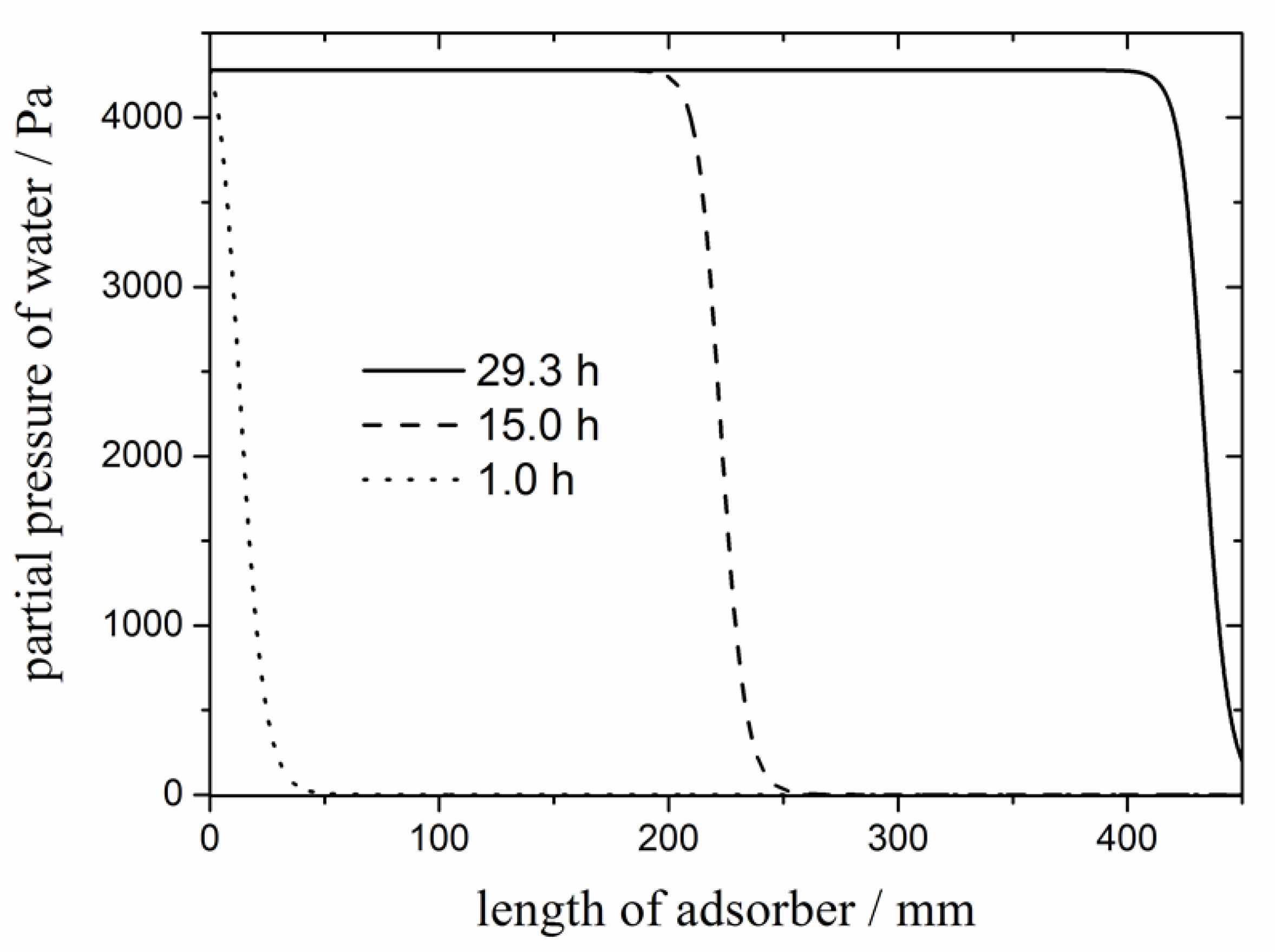
The second option is adsorption of water on a high surface material. Dry zeolites can take up water from a gas stream at ambient temperature without adsorbing nameable amounts of hydrogen [24]. However, the zeolite needs to be regenerated from time to time. Drying a hydrogen stream of 190 g/h with a water content of 850 ppm (corresponding to saturation at 30 °C) by a zeolite 4A bed with a diameter of 5 cm and a length of 45 cm would require replacement after about 29.3 h (Figure 1; calculations based on isotherm data taken from [25]). For a technical process, this duration until breakthrough is somewhat short. Yet, larger adsorber beds can increase this duration. Taking into account that capacity scales with the square of the adsorber bet diameter (and that 5 cm is not a very thick adsorber) operation over several days without regeneration seems possible. However, regular regeneration of the zeolite packing will be required.
Replacing a disposable zeolite packing does not seem to be a viable option. Hence, regeneration within the system is required. Two principle operation modes are possible: pressure swing and temperature swing adsorption. This means that either pressure is reduced for desorption or temperature is increased. In many cases, a combination of both is applied. In the context of an LOHC system, temperature increase is an interesting option, since the heat released by the exothermal hydrogenation reaction might be used for desorption. A process simulation showed that the energy demand for regeneration corresponds to about 0.21% of the lower heating value of the hydrogen (assumption: reduction to 33 g water per 1 kg zeolite). This is slightly worse than for drying based on refrigeration. However, the difference is still within the margin of uncertainty.
A further drawback of adsorption-based drying is the fact that desorption would require a sweep gas. Dry nitrogen would be a possibility, but is not a preferable solution for technical applications. Utilization of a share of the dried hydrogen is more reasonable. At elevated temperatures, this hydrogen can take up large amounts of hydrogen. Subsequently, it is dried again by condensation.
The last major alternative is a membrane process. Permeation causes a pressure drop, which is undesired for hydrogen. Thus, it is preferable to use a membrane that is selectively permeated by water. Sulfonated tetrafluoroethylene (usually known as Nafion®) is a potential membrane material for this purpose and already used in PEM electrolysis systems [26]. A partial pressure for water below the desired one in the hydrogen stream is required on the permeate site of the membrane. Hence, a dry sweep gas must be circulated on the permeate site. To recycle this sweep gas, it has to be dried as well. Cryogenic drying is not an option, because the issues described above would be even more severe due to the lower water content. Adsorption on a zeolite is a more reasonable option. In contrast to direct adsorptive drying, the zeolite is not in direct contact with hydrogen and losses during desorption can therefore be reduced. Furthermore, start-up might be faster, since the pressure of all hydrogen-containing parts remains constant during regeneration. The energy demand for the respective membrane option seems to be the smallest for all options under consideration (about 0.18 % of the lower heating value).
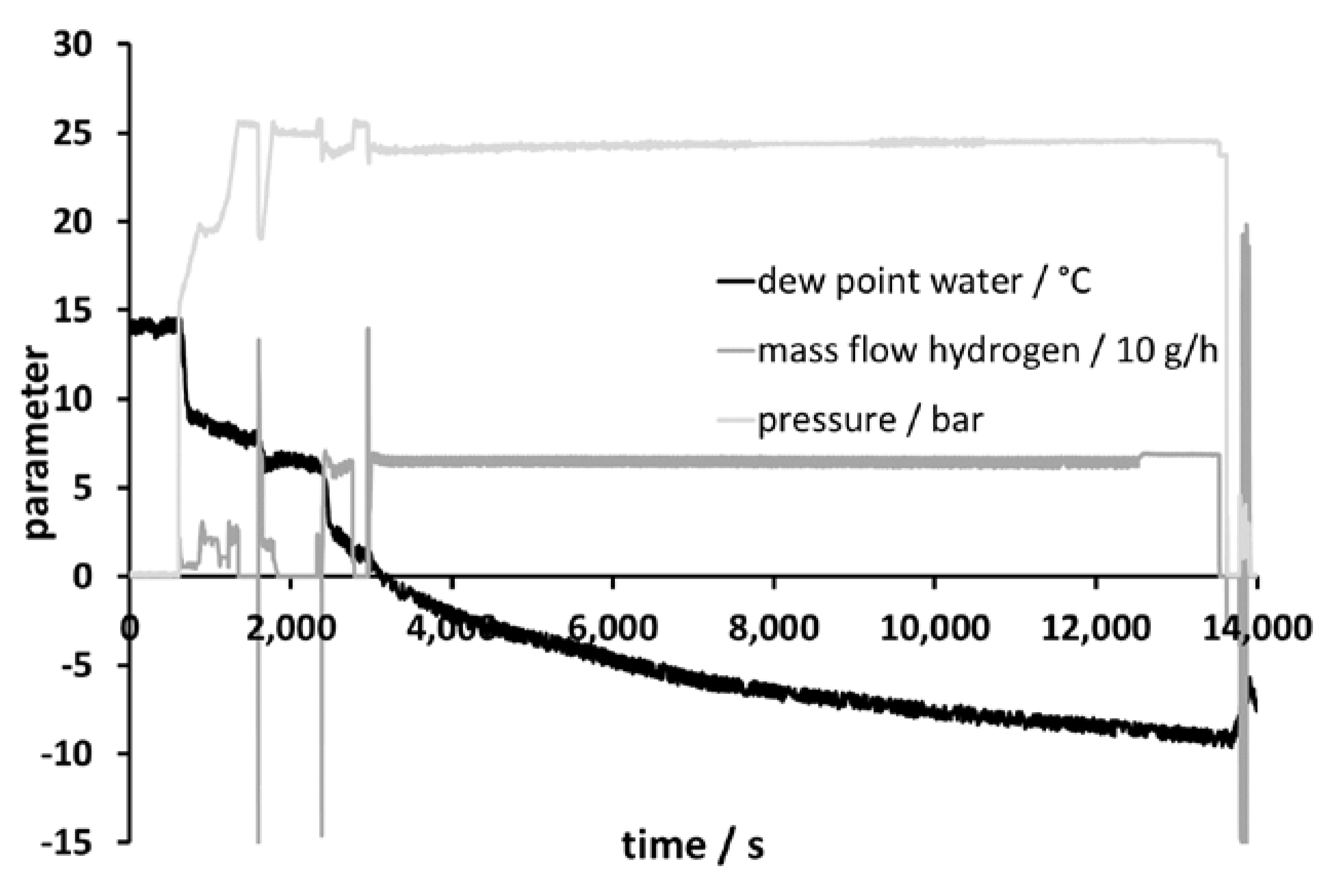
Figure 2 shows the behavior of the membrane system during start-up. The system required about 20 min to reach steady state. This should be taken into consideration for dynamic operation of LOHC systems fed with hydrogen from electrolysis driven by fluctuating sources. In a modified version of this approach, hydrogen could function as the sweep gas. This has the advantage of reduced hydrogen permeation through the membrane, because the hydrogen partial pressures on both sides of the membrane would be similar.
After the laboratory-scale tests, a membrane simulation based on a discretization of partial pressure fractions was performed and linked to the experimental results. Based on this, upscaling to the boundary conditions of the real electrolysis with flow control could be done.
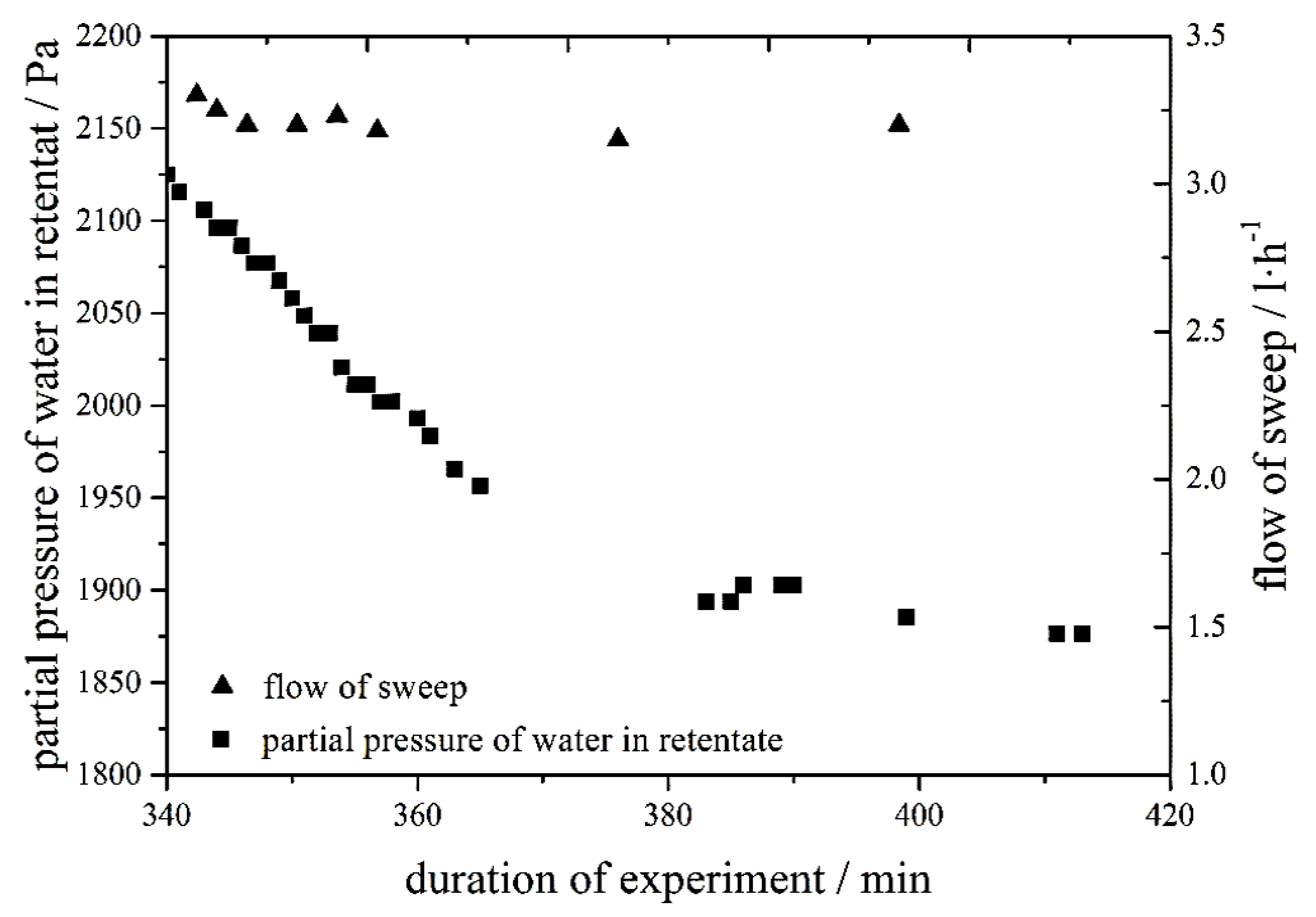
With the scaled-up setup, the predefined solubility boundary condition of 100 ppm could be achieved. As can be seen in Figure 3, the time needed to reach a stationary operation mode has increased compared to the small, laboratory-scale unit. For technical apparatuses, it might therefore be reasonable to avoid full dynamic operation, but rather work within a certain range around a standard operation point.
The membrane tests have been performed with a Nafion™-based membrane. However, there is a huge number of other membrane materials that can be used for drying of gas streams. Yet, the high permeability of hydrogen causes a high loss of hydrogen with most other materials. Thus, Nafion was chosen for this investigation. The permeation coefficients of water in Nafion are, depending on the conditions, up to 500,000 times larger than the permeation coefficient of hydrogen [27]. It can thus be concluded that sufficient selectivities are realistic.
3.3. Liquid–Liquid Phase Separation
If the drying of the hydrogen was not sufficient (e.g., during start-up) or water is introduced to the system via the catalyst, a liquid–liquid phase separation can occur. Even with highly dry hydrogen taken from a gas bottle such a phase separation can be observed. During the first hours of hydrogenation with a new catalyst, the solution is homogeneous, but after cooling to ambient temperature, an emulsion is formed due to the lower solubility. The phase separation opens an opportunity for rather easy water removal by decantation of the aqueous phase. Nevertheless, the two liquid phases have to be separated first. Especially emulsions of water in hydrogenated H18-DBT are quite stable and settling often takes several days. To achieve phase separation in a reasonable timeframe, measures to enhance settling are required.
For the structured packing, no phase separation could be observed optically, neither for an emulsion of water in hydrogenated nor in dehydrogenated H0/18-DBT. With the mesh packing, the phases separated, but still visible droplets of water were still observed within the organic phase. The best phase separation was observed with the glass wool packing. Here, total phase separation occurred and no droplets were visible in any of the phases.
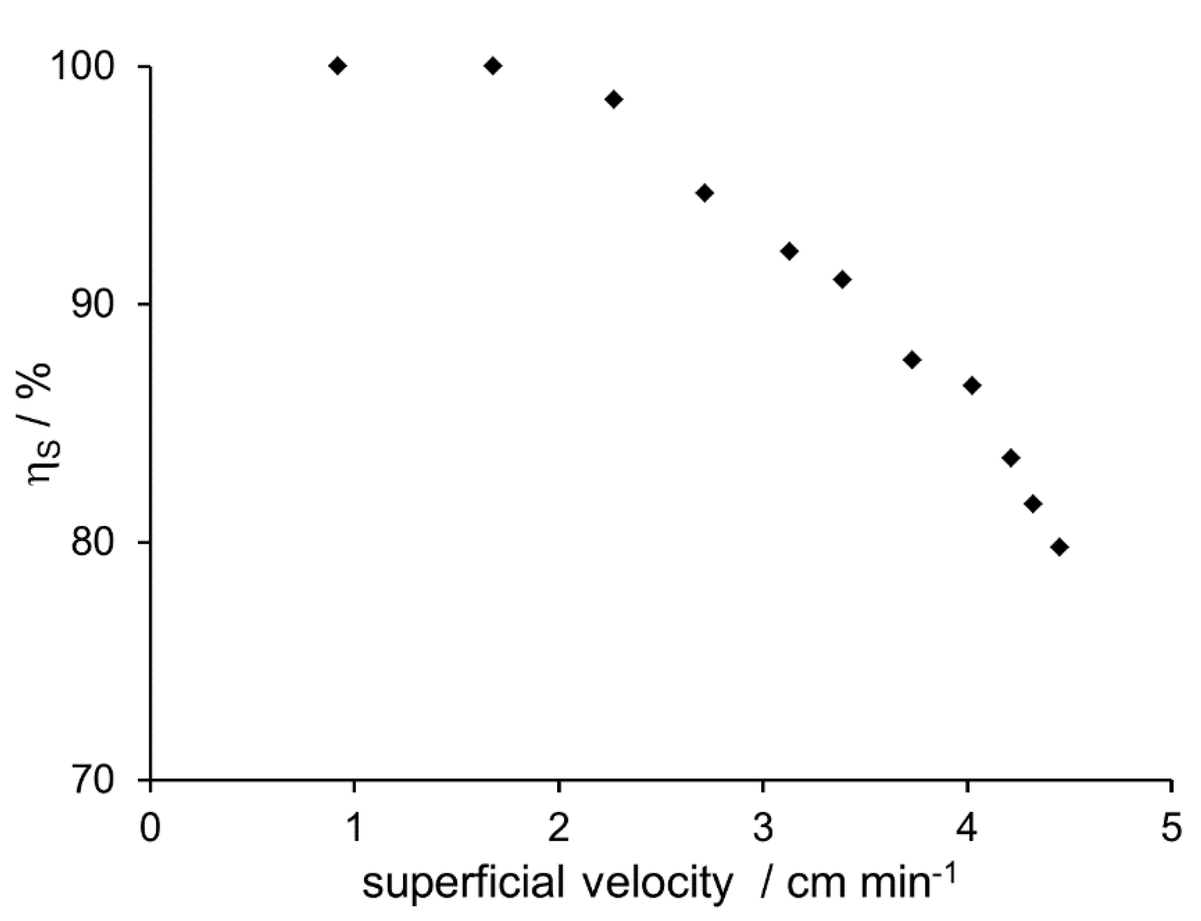
To ensure the capability of the glass wool for phase separation, the volume flow of the emulsion was increased. Optically, full separation was achieved even when the superficial velocity was increased by a factor of 5. However, to ensure that total phase separation was reached, the water content of the organic phase was measured by Karl-Fischer titration (Mettler Toledo C20, Columbus, OH, USA). As long as the water content is equal to the saturation limit, full phase separation can be assumed. If the measured water content is higher, small droplets (below the visible detection limit) must be present and phase separation thus is not complete. To evaluate the quality of the phase separation, the separation efficiency was defined:
where is the amount of water that can thermodynamically be solved and is the amount of water actually measured. If the ratio becomes smaller than unity (or 100%) phase separation is not complete but water droplets exist within the organic phase.
Up to a volume flow of 6.5 mL min−1 (corresponding to a superficial velocity of about 2 cm min−1), the water content equals the solubility. However, at higher speeds, water content increased corresponding to decreasing separation efficiency (Figure 4). Thus, it can be concluded that volume flow may not exceed a certain threshold, equivalent to a superficial velocity of about 2 cm min−1.
When dealing with the phase separation, a further aspect should be considered. Density of H0/18-DBT is depending on the degree of hydrogenation. In case of hydrogenated H18-DBT, the LOHC would form the upper phase. In case of dehydrogenated H0-DBT, the LOHC would form the lower phase. Splitting the emulsion will most likely be done with the hydrogenated form. If the degree of hydrogenation goes down to about 30%, densities of the partially hydrogenated dibenzyl toluene and water would be equal. Therefore, it is required for a reasonable separation to ensure that the degree of hydrogenation is significantly above this limit.
3.4. Drying of Homogeneous LOHC
Phase separation and removal of the aqueous phase ensures that the water content does not exceed a certain threshold determined by solubility. In case of the hydrogenated material, the amount of water would only be 0.006 mass-% at 22.3 °C [23]. Since solubility in subsequent process steps is higher (due to higher temperature or polarizability of the dehydrogenated material), formation of emulsions in later steps is unlikely. Nevertheless, one might want to further decrease the water content to avoid accumulation or issues related to the interaction of water with the dehydrogenation catalyst.
Drying of the homogenous LOHC might be done by heating and evaporation of the water, which has a significantly higher vapor pressure than LOHC. However, this approach suffers from a number of drawbacks. The most important ones are that the heating of the LOHC causes additional energy demand and partial evaporation of the carrier material. Even though the vapor pressure of water is higher than that of (hydrogenated) H18-DBT, some of the H18-DBT would be evaporated. This causes losses of LOHC material and contamination of the water. Another alternative would be the use of a membrane through which water selectively permeates. The disadvantage of this approach is the additional space demand, which has a strong negative effect on the effective energy density of the storage. Hence, it would be advantageous to have a drying technology that can be applied within the tank or in its inlet or outlet.
Introduction of a zeolite into a compartment of the tank would be an option. Many zeolites preferably adsorb water and could, therefore, be applied for removing water from the homogeneous phase. Such an additional adsorptive drying should be applied in the tank with the hydrogenated H18-DBT because water transfer into the dehydrogenation reactor should be avoided. Due to the nine times higher solubility, the maximum water content in dehydrogenated H0-DBT after phase separation is so high that unacceptably large amounts of zeolite would be required for adsorbing the water. Furthermore, the π-system of dehydrogenated H0-DBT shows strong interaction with the zeolite itself. This might cause a significant adsorption of H0-DBT on the zeolite (as it has been observed for aromatics on zeolites [28]), which competes with the adsorption of water.
Zeolite 4A and 13X showed the best performance for drying of water saturated hydrogenated H18-DBT. At a ratio of 0.3‰ (Zeolite/LOHC), the water content can be decreased to 33.4 ± 5.0 ppm. If the ratio is increased to 0.7‰, the concentration of water can be reduced to 16.9 ± 5.0 ppm (Figure 5).
4. Conclusions
Water can accumulate in LOHC systems via multiple routes. The most important ways are wet hydrogen from electrolysis and moisture on the catalyst. This water can cause problems in the catalytic reactions. A particular risk is imposed by the formation of two liquid phases. A separate aqueous phase can, among other issues, cause corrosion problems. Different concepts for the removal of water from LOHC systems have been evaluated.
Already drying the hydrogen, before getting into contact with the LOHC, is generally preferable. Membrane processes are demonstrated to be the best option. Water permeates through the membrane, while hydrogen just passes by with only a negligible pressure drop. The sweep gas on the permeate site of the membrane can be dried by different means, such as adsorption on a zeolite.
If the hydrogen is not sufficiently dried or larger amounts of water comes into the system via the hydrogenation catalyst, liquid–liquid demixing occurs. This can cause many problems, but also opens an opportunity for water removal. To remove the aqueous phase, it is required to achieve phase separation to split the emulsion into two continuous phases. Introduction of glass wool is the simplest way of separating the two liquid phases.
Further drying of the homogenous organic phase below the solubility limit is challenging. Introduction of a zeolite is an option, and the amount of zeolite required would be acceptably low for one cycle. However, due to the huge number of cycles in practical applications, quite large amounts are needed. Furthermore, regeneration of the loaded zeolite is difficult since it is soaked with the LOHC material. It is recommended to reduce the moisture content of hydrogen as much as possible before contact with the LOHC. If an aqueous phase is still formed, it should be removed by means of liquid–liquid separation. However, further drying of the liquid phase is not advisable from a practical perspective.
Author Contributions
Conceptualization, K.M. and W.A.; formal analysis, K.M., R.A., C.K. and A.F.; investigation, R.A., C.K., A.F.; writing—original draft preparation, K.M., R.A., C.K. and A.F.; writing—review and editing, K.M.; visualization, R.A., C.K. and A.F.; supervision, K.M. and W.A. All authors have read and agreed to the published version of the manuscript.
Funding
This research received no external funding.
Acknowledgments
The authors wish to thank Peter Wasserscheid, Andreas Bösmann, Marcus Koch, and Michael Müller for the provision of hydrogenated H18-DBT samples and Alexander Pietschak, Patrick Inhetveen and Vito-Oronzo Milella for the assistance in some of the drying experiments. A special thank goes to Raschig company for provision of the packing materials.
Conflicts of Interest
The authors declare no conflict of interest.
References
- Hua, T.Q.; Ahluwalia, R.K.; Peng, J.K.; Kromer, M.; Lasher, S.; McKenney, K.; Law, K.; Sinha, J. Technical assessment of compressed hydrogen storage tank systems for automotive applications. Int. J. Hydrogen Energy 2011, 36, 3037–3049. [Google Scholar] [CrossRef] [Green Version]
- Züttel, A. Hydrogen storage methods. Naturwissenschaften 2004, 91, 157–172. [Google Scholar] [CrossRef] [PubMed]
- Adametz, P.; Müller, K.; Arlt, W. Efficiency of low-temperature adsorptive hydrogen storage systems. Int. J. Hydrogen Energy 2014, 39, 15604–15613. [Google Scholar] [CrossRef]
- Sakintuna, B.; Lamari-Darkrim, F.; Hirscher, M. Metal hydride materials for solid hydrogen storage: A review. Int. J. Hydrogen Energy 2007, 32, 1121–1140. [Google Scholar] [CrossRef]
- Müller, B.; Müller, K.; Teichmann, D.; Arlt, W. Energy Storage by CO2 Methanization and Energy Carrying Compounds: A Thermodynamic Comparison. Chem. Ing. Tech. 2011, 83, 2002–2013. [Google Scholar] [CrossRef]
- Trost, T.; Horn, S.; Jentsch, M.; Sterner, M. Erneuerbares Methan: Analyse der CO2-Potenziale für Power-to-Gas Anlagen in Deutschland. Z. Energiewirtsch. 2012, 36, 173–190. [Google Scholar] [CrossRef]
- Müller, K.; Geng, J.; Völkl, J.; Arlt, W. Energetic Evaluation of the Feeding-in of Hydrogen into the Natural Gas Distribution System. Chem. Ing. Tech. 2012, 84, 1513–1519. [Google Scholar] [CrossRef]
- Aslam, R.; Khan, M.H.; Ishaq, M.; Müller, K. Thermophysical Studies of Dibenzyltoluene and Its Partially and Fully Hydrogenated Derivatives. J. Chem. Eng. Data 2018, 63, 4580–4587. [Google Scholar] [CrossRef]
- Jorschick, H.; Dürr, S.; Preuster, P.; Bösmann, A.; Wasserscheid, P. Operational Stability of a LOHC-Based Hot Pressure Swing Reactor for Hydrogen Storage. Energy Technol. 2019, 7, 146–152. [Google Scholar] [CrossRef] [Green Version]
- Niermann, M.; Drünert, S.; Kaltschmitt, M.; Bonhoff, K. Liquid organic hydrogen carriers (LOHCs)—Techno-economic analysis of LOHCs in a defined process chain. Energy Environ. Sci. 2019, 12, 290–307. [Google Scholar] [CrossRef]
- Brückner, N.; Obesser, K.; Bösmann, A.; Teichmann, D.; Arlt, W.; Dungs, J.; Wasserscheid, P. Evaluation of Industrially Applied Heat-Transfer Fluids as Liquid Organic Hydrogen Carrier Systems. ChemSusChem 2014, 7, 229–235. [Google Scholar] [CrossRef] [PubMed]
- Markiewicz, M.; Zhang, Y.Q.; Bosmann, A.; Bruckner, N.; Thoming, J.; Wasserscheid, P.; Stolte, S. Environmental and health impact assessment of Liquid Organic Hydrogen Carrier (LOHC) systems—Challenges and preliminary results. Energy Environ. Sci. 2015, 8, 1035–1045. [Google Scholar] [CrossRef] [Green Version]
- Müller, K.; Stark, K.; Emel’yanenko, V.N.; Varfolomeev, M.A.; Zaitsau, D.H.; Shoifet, E.; Schick, C.; Verevkin, S.P.; Arlt, W. Liquid Organic Hydrogen Carriers: Thermophysical and Thermochemical Studies of Benzyl- and Dibenzyl-toluene Derivatives. Ind. Eng. Chem. Res. 2015, 54, 7967–7976. [Google Scholar] [CrossRef]
- Carmo, M.; Fritz, D.L.; Mergel, J.; Stolten, D. A comprehensive review on PEM water electrolysis. Int. J. Hydrogen Energy 2013, 38, 4901–4934. [Google Scholar] [CrossRef]
- Stoots, C.M.; O’Brien, J.E.; Condie, K.G.; Hartvigsen, J.J. High-temperature electrolysis for large-scale hydrogen production from nuclear energy—Experimental investigations. Int. J. Hydrogen Energy 2010, 35, 4861–4870. [Google Scholar] [CrossRef]
- Aswathy, P.; Gandhimathi, R.; Ramesh, S.T.; Nidheesh, P.V. Removal of organics from bilge water by batch electrocoagulation process. Sep. Purif. Tech. 2016, 159, 108–115. [Google Scholar] [CrossRef]
- Liu, N.; Li, L.; McPherson, B.; Lee, R. Removal of organics from produced water by reverse osmosis using MFI-type zeolite membranes. J. Membr. Sci. 2008, 325, 357–361. [Google Scholar] [CrossRef]
- Kujawski, W. Pervaporative Removal of Organics from Water Using Hydrophobic Membranes. Binary Mixtures. Sep. Sci. Technol. 2000, 35, 89–108. [Google Scholar] [CrossRef]
- Williams, D.B.G.; Lawton, M. Drying of Organic Solvents: Quantitative Evaluation of the Efficiency of Several Desiccants. J. Org. Chem. 2010, 75, 8351–8354. [Google Scholar] [CrossRef]
- Joshi, S.; Fair, J.R. Adsorptive drying of toluene. Ind. Eng. Chem. Res. 1988, 27, 2078–2085. [Google Scholar] [CrossRef]
- Laguntsov, N.I.; Kagramanov, G.G.; Kurchatov, I.M.; Karaseva, M.D. Natural gas drying and cleaning of carbon dioxide by membrane gas separation. Pet. Chem. 2017, 57, 132–138. [Google Scholar] [CrossRef]
- LaCasse, G.A.; Ingvordsen, T. Desiccant Drying of Gas Pipelines. In Proceedings of the National Association of Corrosion Engineers Meeting, St. Louis, MO, USA, 21–25 March 2016. [Google Scholar]
- Aslam, R.; Müller, K.; Arlt, W. Experimental Study of Solubility of Water in Liquid Organic Hydrogen Carriers. J. Chem. Eng. Data 2015, 60, 1997–2002. [Google Scholar] [CrossRef]
- Zielinski, J.; Coe, C.; Nickel, R.; Romeo, A.; Cooper, A.; Pez, G. High pressure sorption isotherms via differential pressure measurements. Adsorption 2007, 13, 1–7. [Google Scholar] [CrossRef]
- Gorbach, A.; Stegmaier, M.; Eigenberger, G. Measurement and Modeling of Water Vapor Adsorption on Zeolite 4A—Equilibria and Kinetics. Adsorption 2004, 10, 29–46. [Google Scholar] [CrossRef]
- Badwal, S.P.S.; Giddey, S.; Ciacchi, F.T. Hydrogen and oxygen generation with polymer electrolyte membrane (PEM)-based electrolytic technology. Ionics 2006, 12, 7–14. [Google Scholar] [CrossRef] [Green Version]
- Rangel-Cárdenas, A.L.; Koper, G.J.M. Transport in Proton Exchange Membranes for Fuel Cell Applications—A Systematic Non-Equilibrium Approach. Materials 2017, 10, 576. [Google Scholar] [CrossRef] [Green Version]
- Yu, M.; Hunter, J.T.; Falconer, J.L.; Noble, R.D. Adsorption of benzene mixtures on silicalite-1 and NaX zeolites. Microporous Mesoporous Mater. 2006, 96, 376–385. [Google Scholar] [CrossRef]
Figure 1.
Breakthrough curve of water for a zeolite 4A bet with a diameter of 5 cm and length of 45 cm.
Figure 1.
Breakthrough curve of water for a zeolite 4A bet with a diameter of 5 cm and length of 45 cm.

Figure 2.
Laboratory-scale membrane experiment for drying 1.0 L h−1 helium counter current with nitrogen 5.0 as sweep (flow at ambient conditions).
Figure 2.
Laboratory-scale membrane experiment for drying 1.0 L h−1 helium counter current with nitrogen 5.0 as sweep (flow at ambient conditions).

Figure 3.
Dew point as a function of time for the continuous prototype hydrogen membrane drying process (stationary operation was achieved after about 3000 s, but the whole data range is shown for the sake of completeness).
Figure 3.
Dew point as a function of time for the continuous prototype hydrogen membrane drying process (stationary operation was achieved after about 3000 s, but the whole data range is shown for the sake of completeness).

Figure 4.
Separation efficiency of the glass wool packing for an emulsion of water and hydrogenated H18-DBT as a function of superficial velocity.
Figure 4.
Separation efficiency of the glass wool packing for an emulsion of water and hydrogenated H18-DBT as a function of superficial velocity.

Figure 5.
Concentration of water in a H18-DBT-sample over time for direct contact of moist liquid organic hydrogen carriers (LOHC) with a zeolite. Ratio zeolite/LOHC-sample is 0.7‰.
Figure 5.
Concentration of water in a H18-DBT-sample over time for direct contact of moist liquid organic hydrogen carriers (LOHC) with a zeolite. Ratio zeolite/LOHC-sample is 0.7‰.

© 2020 by the authors. Licensee MDPI, Basel, Switzerland. This article is an open access article distributed under the terms and conditions of the Creative Commons Attribution (CC BY) license (http://creativecommons.org/licenses/by/4.0/).
Share and Cite
MDPI and ACS Style
Müller, K.; Aslam, R.; Fikrt, A.; Krieger, C.; Arlt, W. Water Removal from LOHC Systems. Hydrogen 2020, 1, 1-10. https://0-doi-org.brum.beds.ac.uk/10.3390/hydrogen1010001
AMA Style
Müller K, Aslam R, Fikrt A, Krieger C, Arlt W. Water Removal from LOHC Systems. Hydrogen. 2020; 1(1):1-10. https://0-doi-org.brum.beds.ac.uk/10.3390/hydrogen1010001
Chicago/Turabian StyleMüller, Karsten, Rabya Aslam, André Fikrt, Christoph Krieger, and Wolfgang Arlt. 2020. "Water Removal from LOHC Systems" Hydrogen 1, no. 1: 1-10. https://0-doi-org.brum.beds.ac.uk/10.3390/hydrogen1010001