Validation of an Intra-Oral Scan Method Versus Cone Beam Computed Tomography Superimposition to Assess the Accuracy between Planned and Achieved Dental Implants: A Randomized In Vitro Study

 ,
, 
 , ,
, ,
Abstract
:1. Introduction
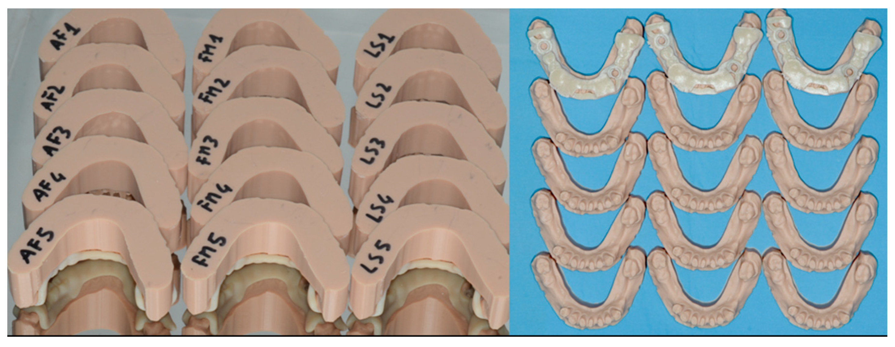
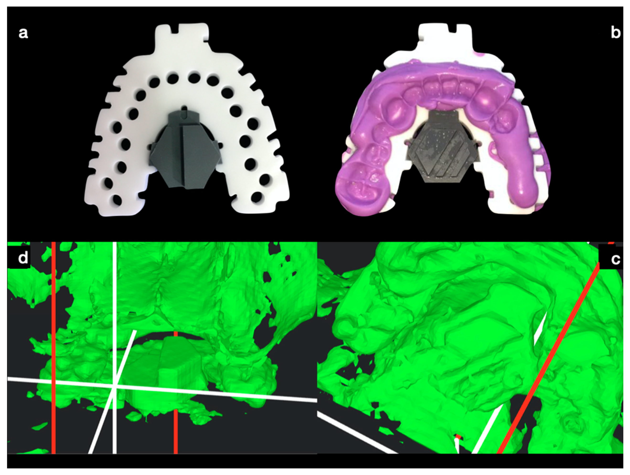
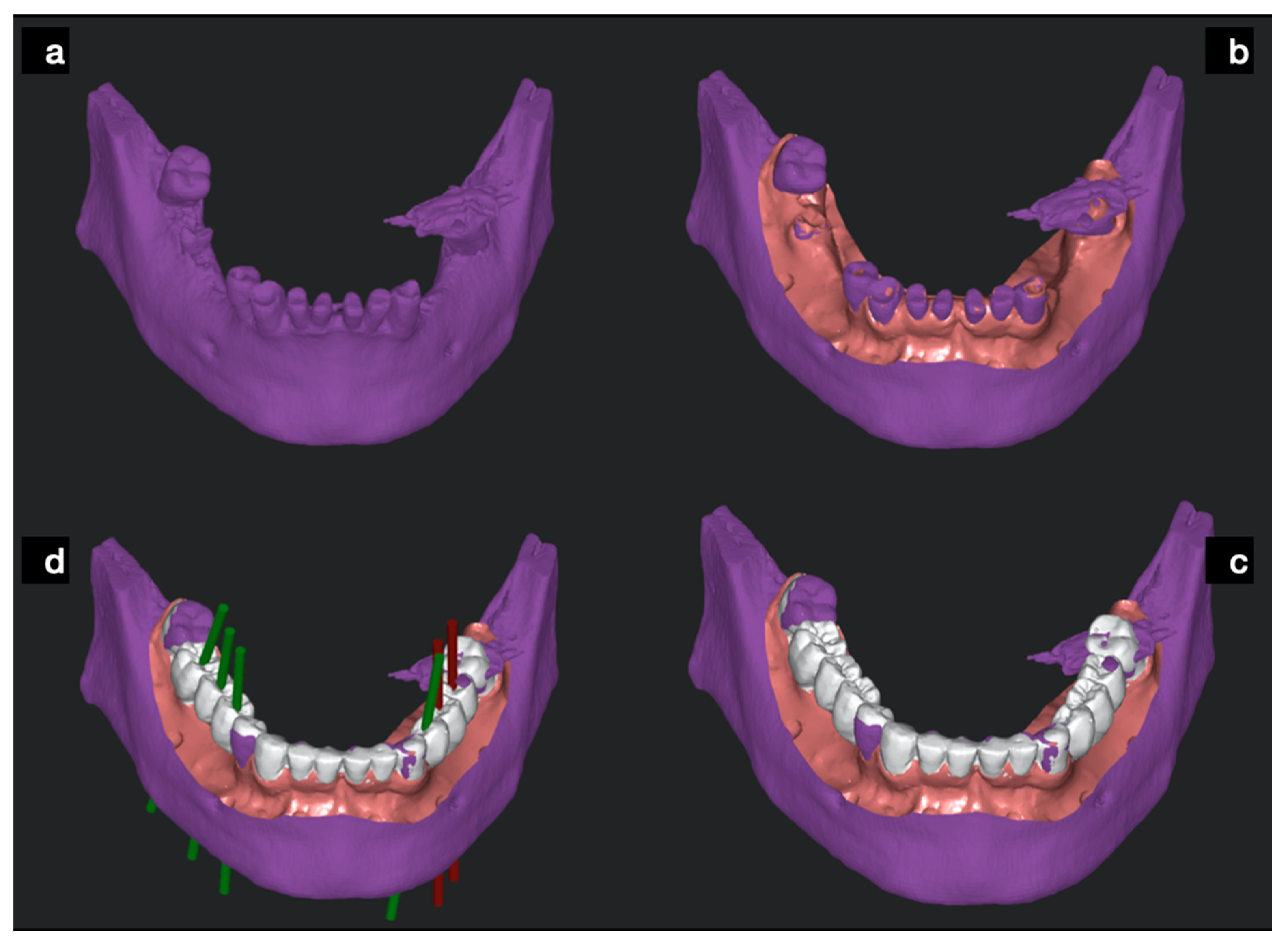
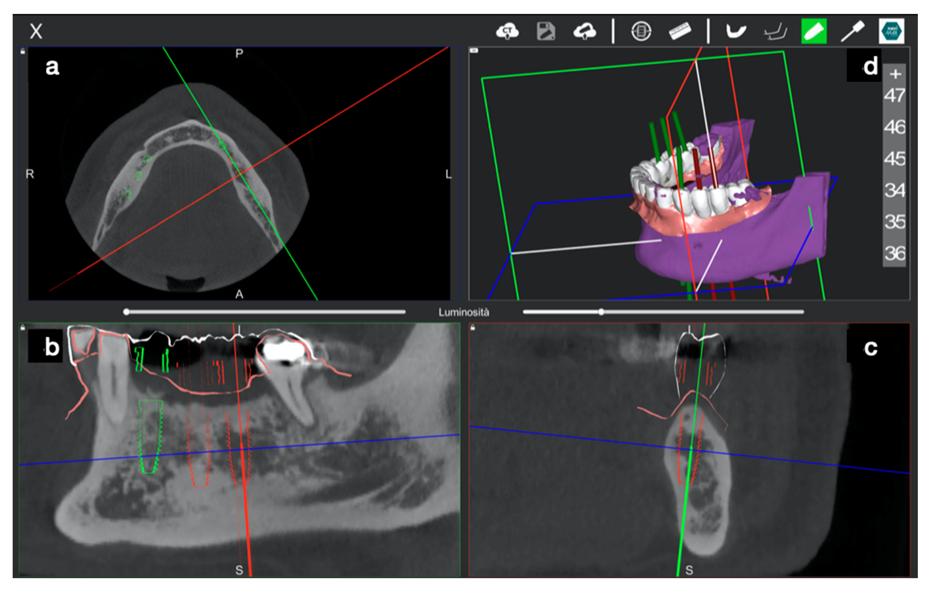
2. Materials and Methods
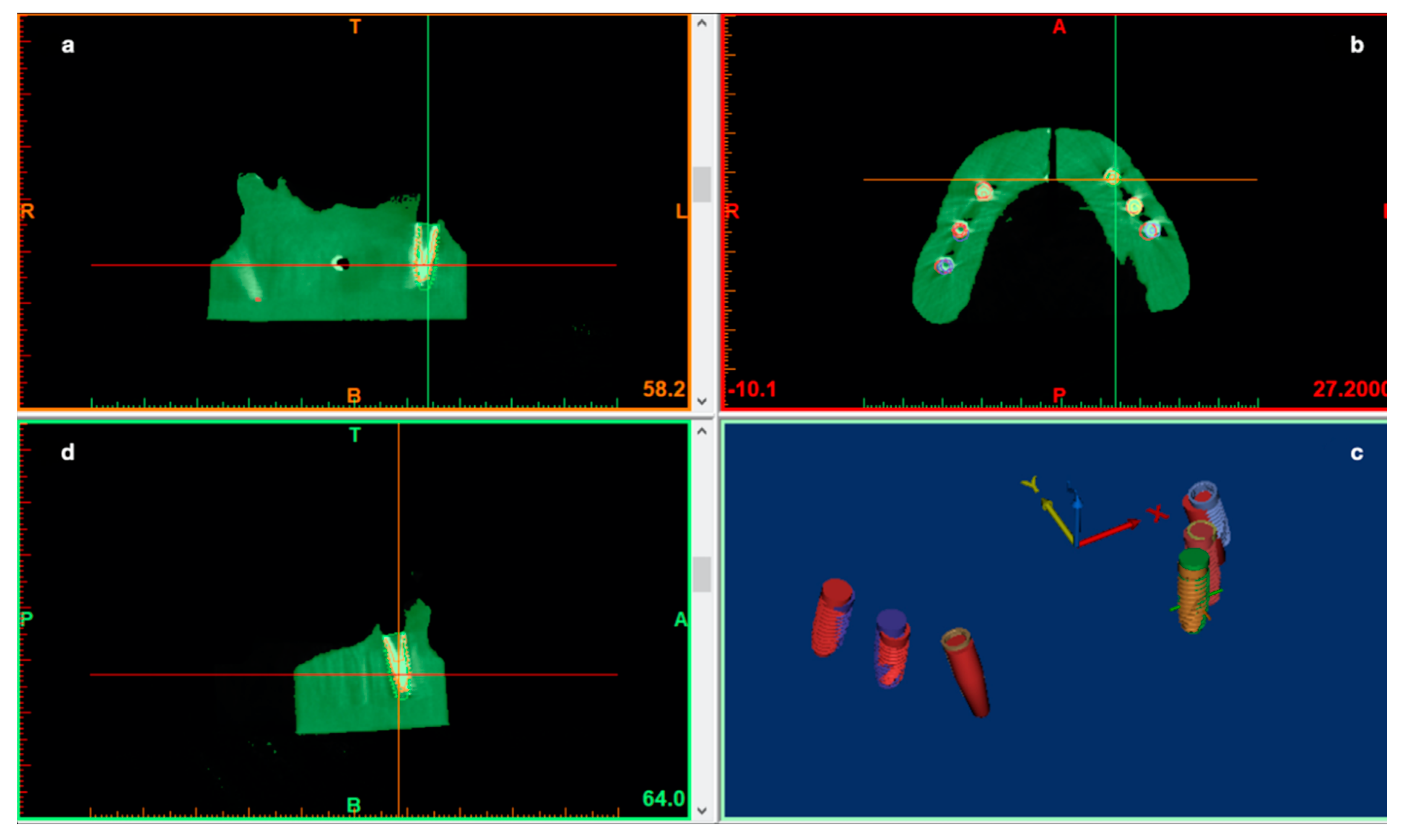
- A comparison between pre-op and post-op CBCT, based on radiographic volume superimposition;
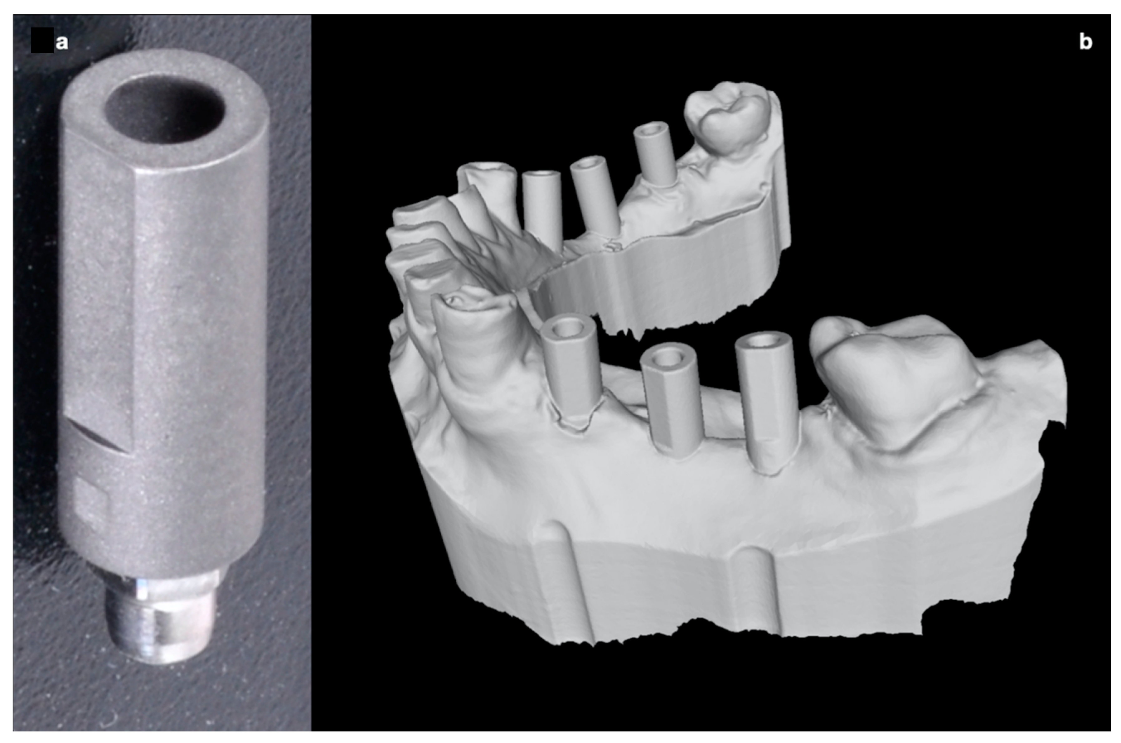
- A comparison between post-op Standard Tessellation Language (STL) files obtained from an intra-oral scan (IOS) of the resin casts and the STL file obtained from the pre-op CBCT implant planning. In this case, the remaining teeth were used to align pre-op and post-op STL files to assess implants deviations.
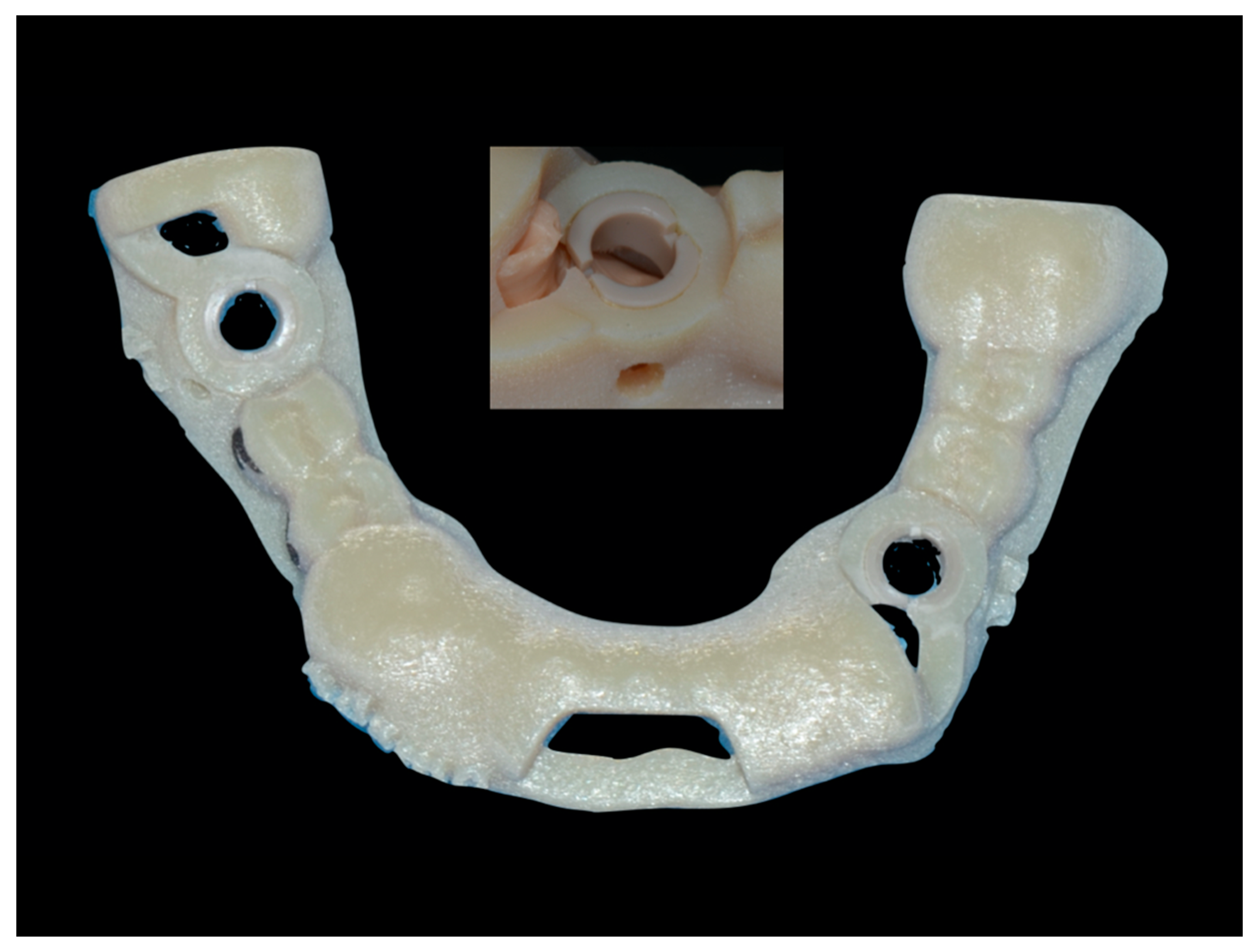
2.1. Static Computer Aided Implantology Workflow (SG)
2.2. Dynamic Computer Aided Implantology Workflow (ND)
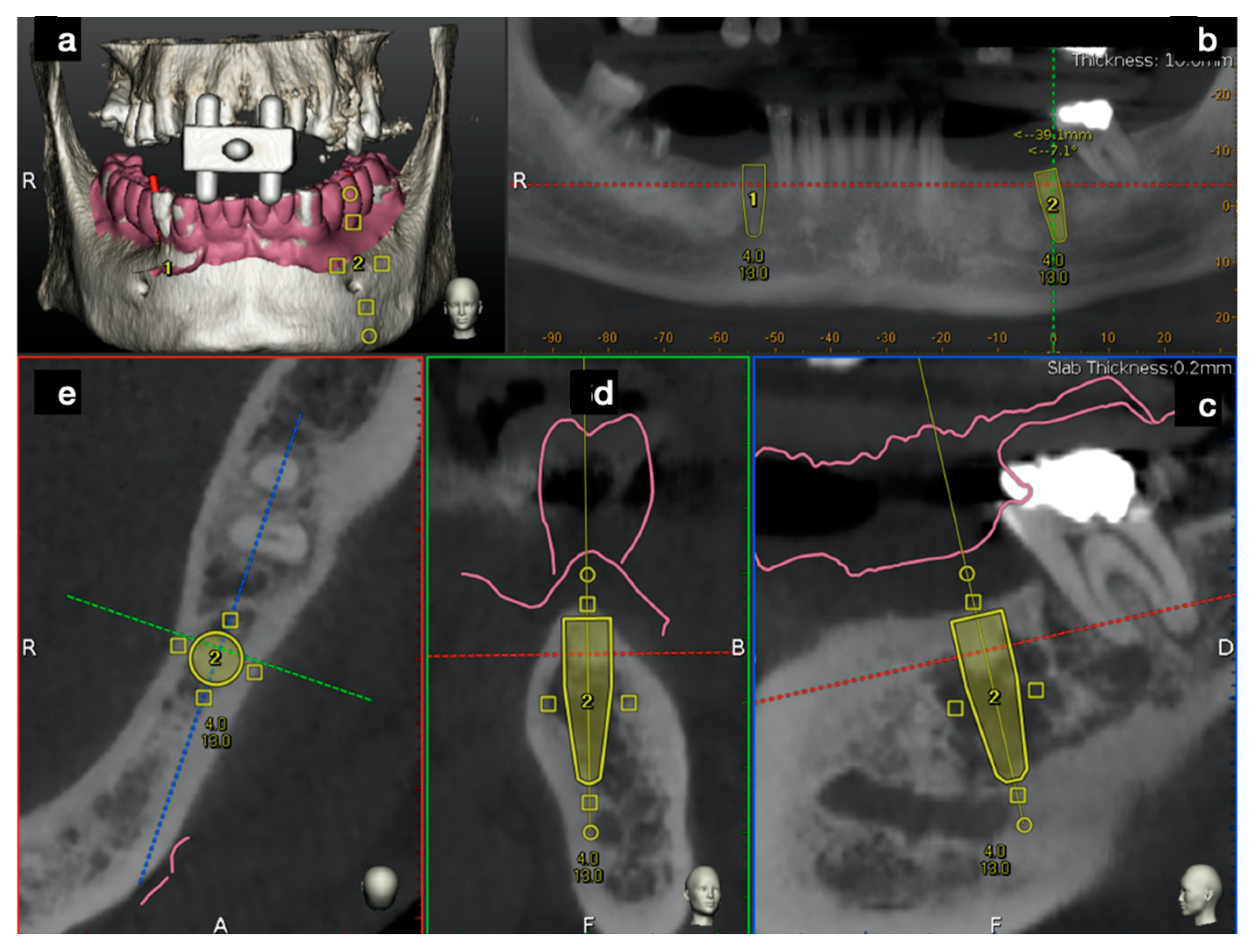
2.2.1. Plan
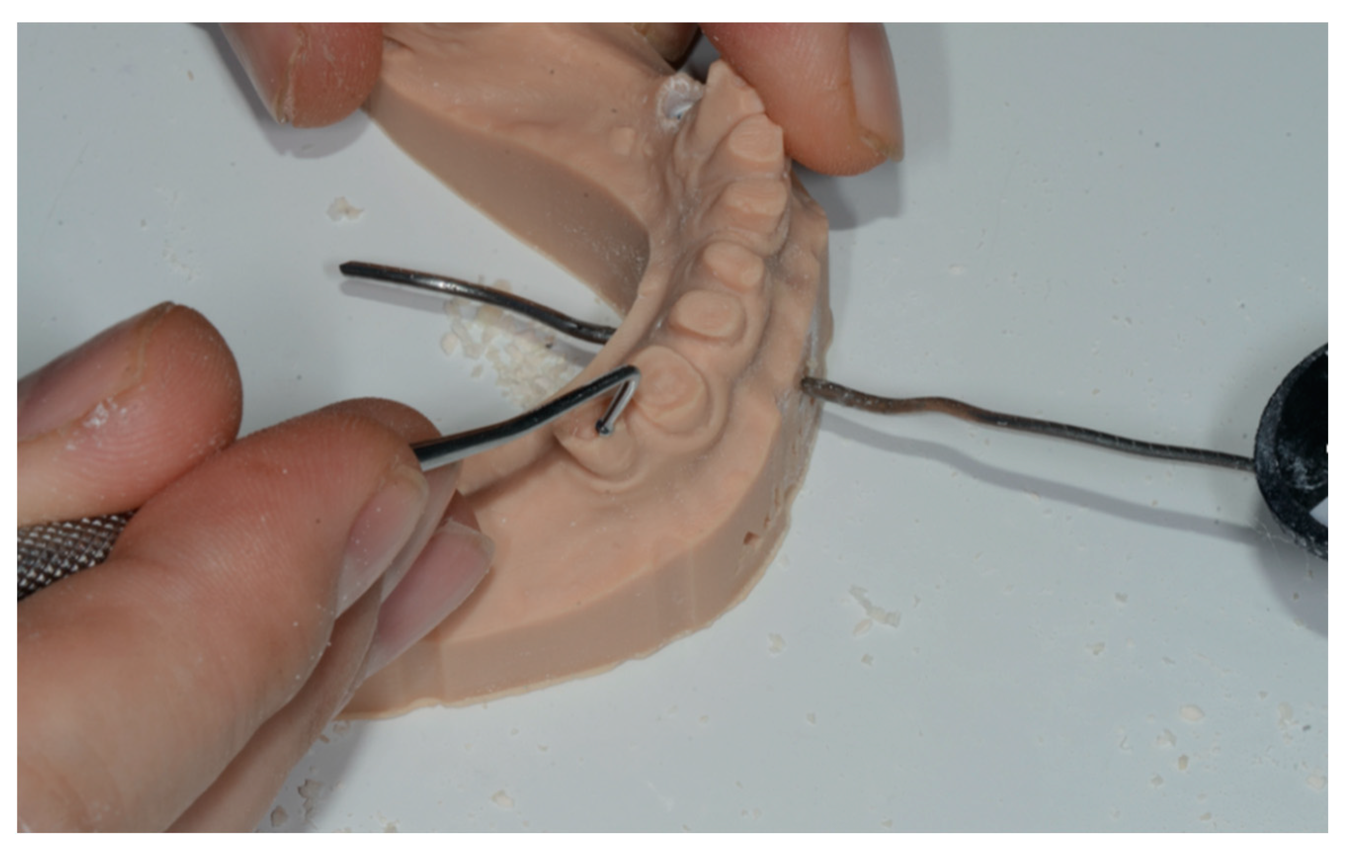
2.2.2. Trace
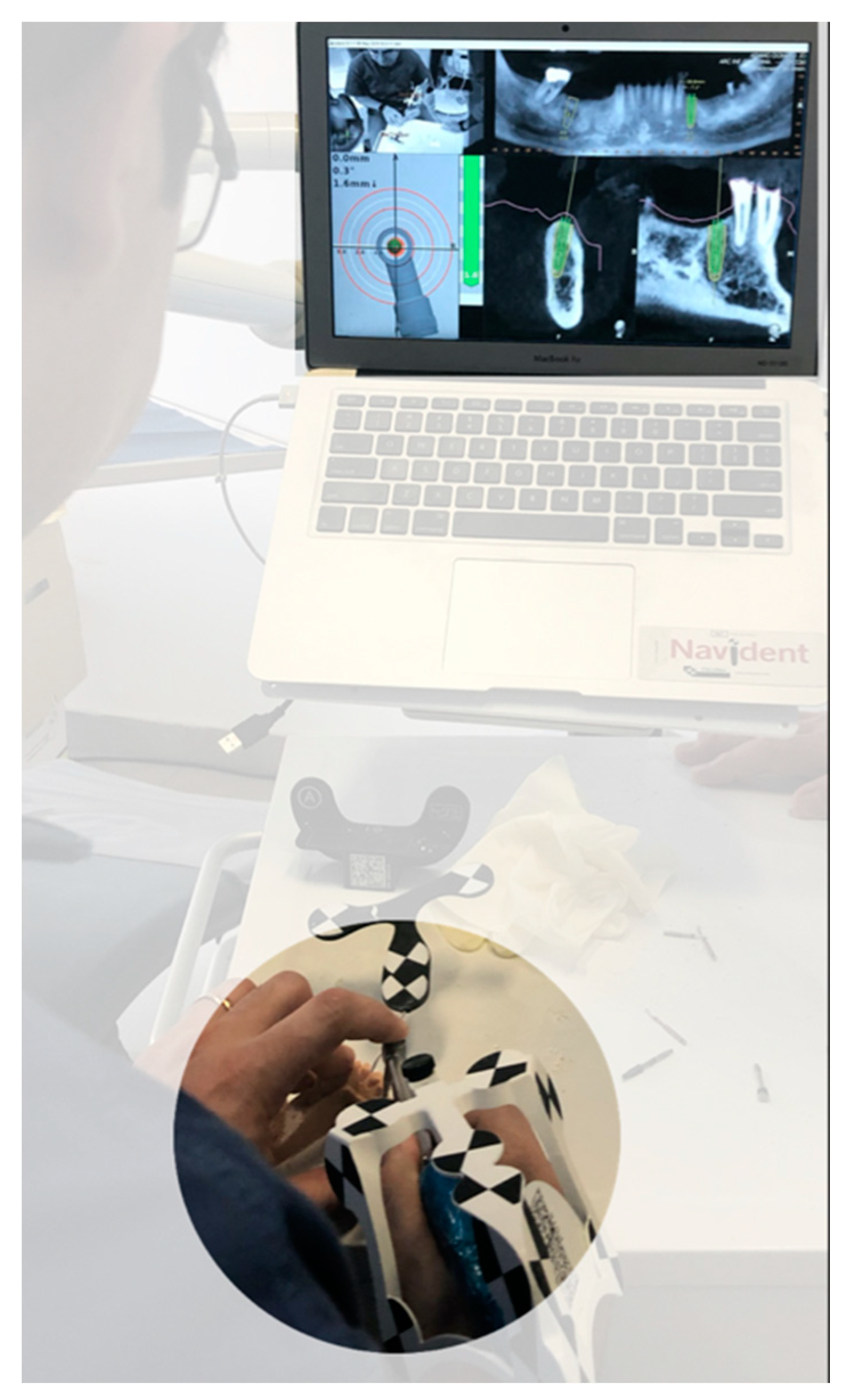
2.2.3. Place
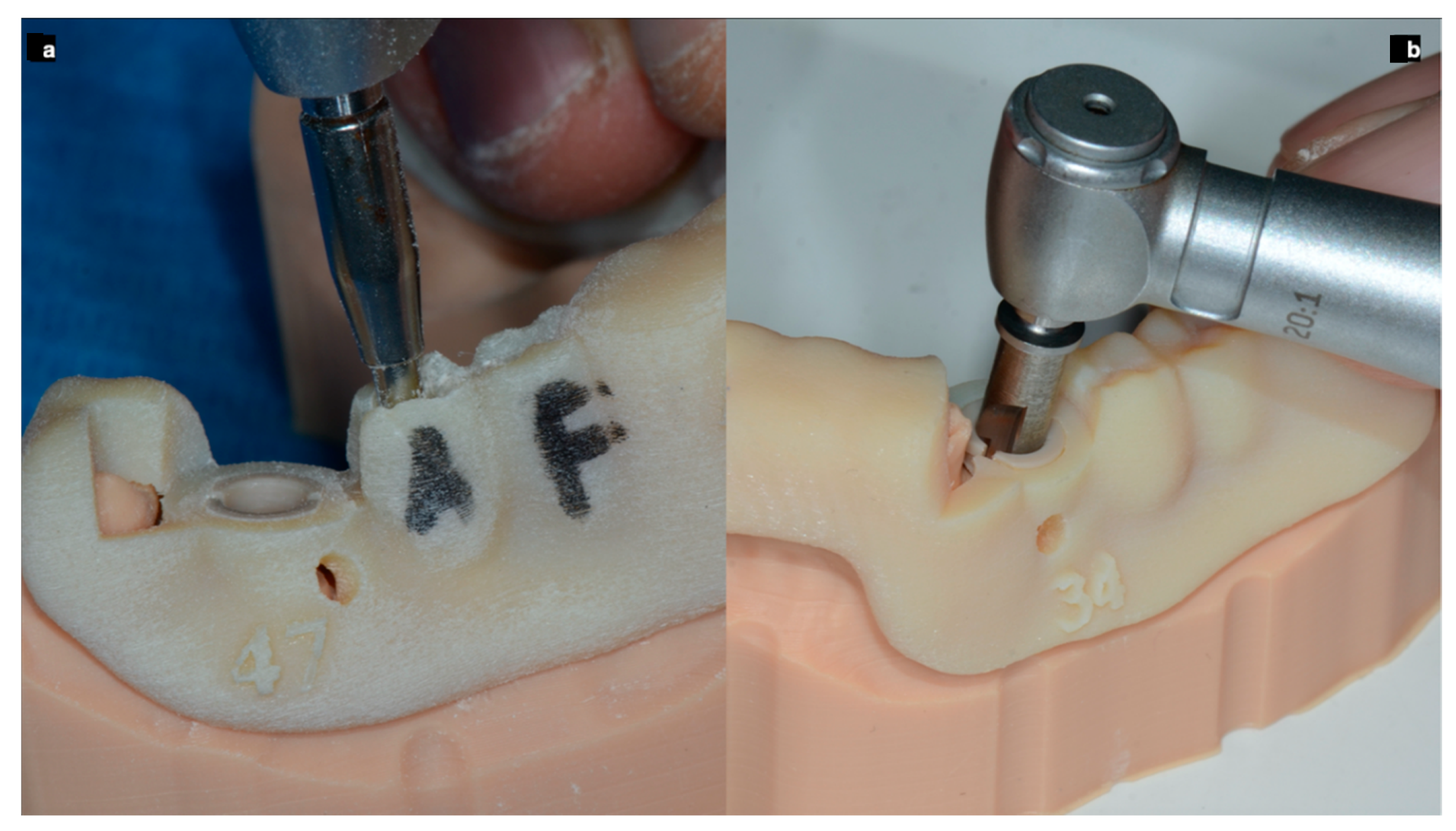
2.3. Free Hand Workflow (FH)
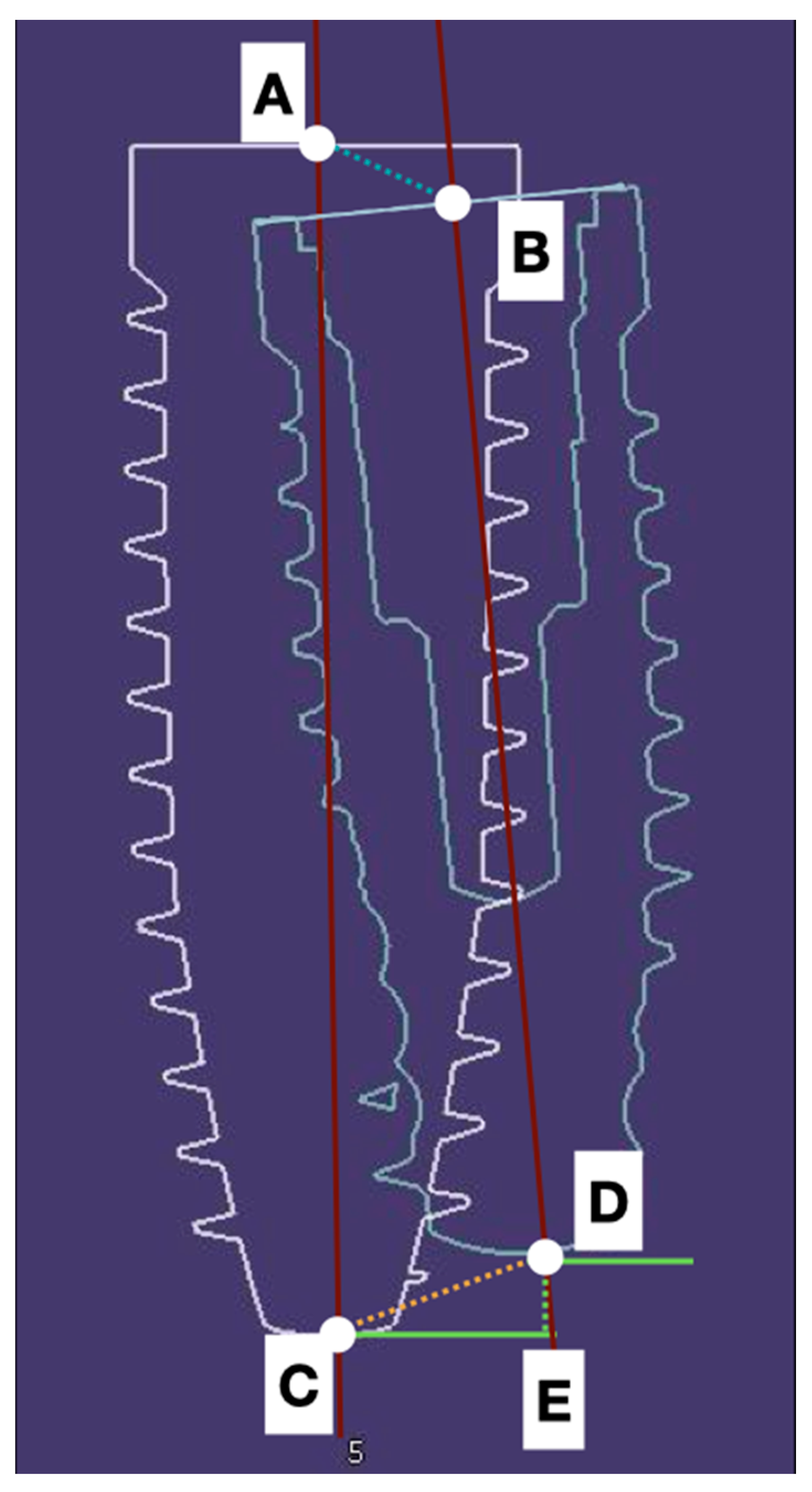
2.4. Digital Data Collection
3. Statistical Analysis
4. Results
5. Discussion
- All the guided dental supported surgeries were more accurate than those using a gingival support;
- The guided surgery is valid to reach an optimal implant placement;
- The use of IOS to compare final placement to implant planning is remarkable because of its accuracy and biological respect.
6. Conclusions
Author Contributions
Funding
Acknowledgments
Conflicts of Interest
References
- Adell, R.; Eriksson, B.; Lekholm, U.; Brånemark, P.I.; Jemt, T. Long-term follow-up study of osseointegrated implants in the treatment of totally edentulous jaws. Int. J. Oral Maxillofac. Implant. 1990, 5, 347–359. [Google Scholar]
- Lang, N.P.; Pjetursson, B.E.; Tan, K.; Brägger, U.; Egger, M.; Zwahlen, M. A systematic review of the survival and c omplication rates of fixed partial dentures (FPDs) after an observation period of at least 5 years. II. Combined tooth--implant-supported FPDs. Clin. Oral Implant. Res. 2004, 15, 643–653. [Google Scholar] [CrossRef] [PubMed]
- Jemt, T.; Johansson, J. Implant treatment in the edentulous maxillae: A 15-year follow-up study on 76 consecutive patients provided with fixed prostheses. Clin. Implant. Dent. Relat. Res. 2006, 8, 61–69. [Google Scholar] [CrossRef] [PubMed]
- Wyatt, C.C.; Pharoah, M.J. Imaging techniques and image interpretation for dental implant treatment. Int. J. Prosthodont. 1998, 11, 442–452. [Google Scholar] [PubMed]
- Guerrero, M.E.; Jacobs, R.; Loubele, M.; Schutyser, F.; Suetens, P.; van Steenberghe, D. State-of-the-art on cone beam CT imaging for preoperative planning of implant placement. Clin. Oral Investig. 2006, 10, 1–7. [Google Scholar] [CrossRef]
- Loubele, M.; Bogaerts, R.; Van Dijck, E.; Pauwels, R.; Vanheusden, S.; Suetens, P.; Marchal, G.; Sanderink, G.; Jacobs, R. Comparison between effective radiation dose of CBCT and MSCT scanners for dentomaxillofacial applications. Eur. J. Radiol. 2009, 71, 461–468. [Google Scholar] [CrossRef]
- Angelopoulos, C.; Scarfe, W.C.; Farman, A.G. A comparison of maxillofacial CBCT and medical CT. Atlas Oral Maxillofac. Surg. Clin. N. Am. 2012, 20, 1–17. [Google Scholar] [CrossRef]
- Jung, R.E.; Schneider, D.; Ganeles, J.; Wismeijer, D.; Zwahlen, M.; Hämmerle, C.H.; Tahmaseb, A. Computer technology applications in surgical implant dentistry: A systematic review. Int. J. Oral Maxillofac. Implant. 2009, 24, 92–109. [Google Scholar]
- Hultin, M.; Svensson, K.G.; Trulsson, M. Clinical advantages of computer-guided implant placement: A systematic review. Clin. Oral Implant. Res. 2012, 23, 124–135. [Google Scholar] [CrossRef]
- Arisan, V.; Karabuda, C.Z.; Mumcu, E.; Özdemir, T. Implant positioning errors in freehand and computer-aided placement methods: A single-blind clinical comparative study. Int. J. Oral Maxillofac. Implant. 2013, 28, 190–204. [Google Scholar] [CrossRef] [Green Version]
- Mailoa, J.; Arnett, B.S.; Chan, H.; George, F.; Kaigler, D.; Wang, H. The association between buccal mucosa thickness and peri-implant bone loss and attachment loss. Implant. Dent. 2018, 27, 575–581. [Google Scholar] [CrossRef] [PubMed]
- Grunder, U.; Gracis, S.; Capelli, M. Influence of the 3-D bone-to-implant relationship on esthetics. Int. J. Periodontics Restor. Dent. 2005, 25, 113–119. [Google Scholar]
- Widmann, G.; Bale, R.J. Accuracy in computer-aided implant surgery—A review. Int. J. Oral Maxillofac. Implant. 2006, 21, 305–313. [Google Scholar]
- Cassetta, M.; Di Mambro, A.; Giansanti, M.; Stefanelli, L.V.; Cavallini, C. The intrinsic error of a stereolithographic surgical template in implant guided surgery. Int. J. Oral Maxillofac. Surg. 2013, 42, 264–275. [Google Scholar] [CrossRef]
- Stefanelli, L.V.; Mandelaris, G.A.; Franchina, A.; Di Nardo, D.; Galli, M.; Pagliarulo, M.; Testarelli, L.; Di Carlo, S.; Gambarini, G. Accuracy Evaluation of 14 Maxillary Full Arch Implant Treatments Performed with Da Vinci Bridge: A Case Series. Materials 2020, 13, 2806. [Google Scholar] [CrossRef]
- Stefanelli, L.V.; Mandelaris, G.A.; Franchina, A.; Pranno, N.; Pagliarulo, M.; Cera, F.; Maltese, F.; Angelis, F.; Carlo, S.D. Accuracy of Dynamic Navigation System Workflow for Implant Supported Full Arch Prosthesis: A Case Series. Int. J. Environ. Res. Public Health 2020, 17, 5038. [Google Scholar] [CrossRef]
- Di Giacomo, G.A.; Cury, P.R.; de Araujo, N.S.; Sendyk, W.R.; Sendyk, C.L. Clinical application of stereolithographic surgical guides for implant placement: Preliminary results. J. Periodontol. 2005, 76, 503–507. [Google Scholar] [CrossRef]
- Ersoy, A.E.; Turkyilmaz, I.; Ozan, O.; McGlumphy, E.A. Reliability of implant placement with stereolithographic surgical guides generated from computed tomography: Clinical data from 94 implants. J. Periodontol. 2008, 79, 1339–1345. [Google Scholar] [CrossRef]
- Skjerven, H.; Olsen-Bergem, H.; Rønold, H.J.; Riis, U.H.; Ellingsen, J.E. Comparison of postoperative intraoral scan versus cone beam computerised tomography to measure accuracy of guided implant placement—A prospective clinical study. Clin. Oral Implant. Res. 2019, 30, 531–541. [Google Scholar] [CrossRef]
- Tang, T.; Liao, L.; Huang, Z.; Gu, X.; Zhang, X. Accuracy of the evaluation of implant position using a completely digital registration method compared with a radiographic method. J. Prosthet. Dent. 2019, 122, 537–542. [Google Scholar] [CrossRef] [Green Version]
- Buser, D.; Martin, W.; Belser, U.C. Optimizing esthetics for implant restorations in the anterior maxilla: Anatomic and surgical considerations. Int. J. Oral Maxillofac. Implant. 2004, 19, 43–61. [Google Scholar]
- Cassetta, M.; Stefanelli, L.V.; Giansanti, M.; Calasso, S. Accuracy of implant placement with a stereolithographic surgical template. Int. J. Oral Maxillofac. Implant. 2012, 27, 655–663. [Google Scholar]
- Arisan, V.; Karabuda, Z.C.; Ozdemir, T. Accuracy of two stereolithographic guide systems for computer-aided implant placement: A computed tomography-based clinical comparative study. J. Periodontol. 2010, 81, 43–51. [Google Scholar] [CrossRef] [PubMed]
- Berdougo, M.; Fortin, T.; Blanchet, E.; Isidori, M.; Bosson, J.L. Flapless implant surgery using an image-guided system. A 1- to 4-year retrospective multicenter comparative clinical study. Clin. Implant. Dent. Relat. Res. 2010, 12, 142–152. [Google Scholar] [CrossRef] [PubMed]
- Bornstein, M.M.; Al-Nawas, B.; Kuchler, U.; Tahmaseb, A. Consensus statements and recommended clinical procedures regarding contemporary surgical and radiographic techniques in implant dentistry. Int. J. Oral Maxillofac. Implant. 2014, 29, 78–82. [Google Scholar] [CrossRef] [PubMed] [Green Version]
- Monje, A.; Chappuis, V.; Monje, F.; Muñoz, F.; Wang, H.L.; Urban, I.A.; Buser, D. The critical peri-implant buccal bone wall thickness revisited: An experimental study in the beagle dog. Int. J. Oral Maxillofac. Implant. 2019, 34, 1328–1336. [Google Scholar] [CrossRef] [PubMed]
- Vercruyssen, M.; Cox, C.; Coucke, W.; Naert, I.; Jacobs, R.; Quirynen, M. A randomized clinical trial comparing guided implant surgery (bone- or mucosa-supported) with mental navigation or the use of a pilot-drill template. J. Clin. Periodontol. 2014, 41, 717–723. [Google Scholar] [CrossRef]
- Tahmaseb, A.; Wu, V.; Wismeijer, D.; Coucke, W.; Evans, C. The accuracy of static computer-aided implant surgery: A systematic review and meta-analysis. Clin. Oral Implant. Res. 2018, 29, 416–435. [Google Scholar] [CrossRef] [Green Version]
- Gunkel, A.R.; Freysinger, W.; Thumfart, W.F. Experience with various 3-dimensional navigation systems in head and neck surgery. Arch. Otolaryngol. Head Neck Surg. 2000, 126, 390–395. [Google Scholar] [CrossRef] [Green Version]
- Siessegger, M.; Mischkowski, R.A.; Schneider, B.T.; Krug, B.; Klesper, B.; Zöller, J.E. Image guided surgical navigation for removal of foreign bodies in the head and neck. J. Cranio Maxillofac. Surg. 2001, 29, 321–325. [Google Scholar] [CrossRef]
- Wanschitz, F.; Birkfellner, W.; Watzinger, F.; Schopper, C.; Patruta, S.; Kainberger, F.; Figl, M.; Kettenbach, J.; Bergmann, H.; Ewers, R. Evaluation of accuracy of computer-aided intraoperative positioning of endosseous oral implants in the edentulous mandible. Clin. Oral Implant. Res. 2002, 13, 59–64. [Google Scholar] [CrossRef] [PubMed]
- Eggers, G.; Haag, C.; Hassfeld, S. Image-guided removal of foreign bodies. Br. J. Oral Maxillofac. Surg. 2005, 43, 404–409. [Google Scholar] [CrossRef] [PubMed]
- Somogyi-Ganss, E.; Holmes, H.I.; Jokstad, A. Accuracy of a novel prototype dynamic computer-assisted surgery system. Clin. Oral Implant. Res. 2015, 26, 882–890. [Google Scholar] [CrossRef] [PubMed]
- Wagner, A.; Wanschitz, F.; Birkfellner, W.; Zauza, K.; Klug, C.; Schicho, K.; Kainberger, F.; Czerny, C.; Bergmann, H.; Ewers, R. Computer-aided placement of endosseous oral implants in patients after ablative tumour surgery: Assessment of accuracy. Clin. Oral Implant. Res. 2003, 14, 340–348. [Google Scholar] [CrossRef]
- Block, M.S.; Emery, R.W.; Lank, K.; Ryan, J. Implant Placement Accuracy Using Dynamic Navigation. Int. J. Oral Maxillofac. Implant. 2017, 32, 92–99. [Google Scholar] [CrossRef]
- Jorba-García, A.; Figueiredo, R.; González-Barnadas, A.; Camps-Font, O.; Valmaseda-Castellón, E. Accuracy and the role of experience in dynamic computer guided dental implant surgery: An in-vitro study. Med. Oral Patol. Oral Cir. Bucal 2019, 24, e76–e83. [Google Scholar] [CrossRef]
- Pellegrino, G.; Taraschi, V.; Andrea, Z.; Ferri, A.; Marchetti, C. Dynamic navigation: A prospective clinical trial to evaluate the accuracy of implant placement. Int. J. Comput. Dent. 2019, 22, 139–147. [Google Scholar]
- Stefanelli, L.V.; DeGroot, B.S.; Lipton, D.I.; Mandelaris, G.A. Accuracy of a Dynamic Dental Implant Navigation System in a Private Practice. Int. J. Oral Maxillofac. Implant. 2019, 34, 205–213. [Google Scholar] [CrossRef]
- Stefanelli, L.V.; Mandelaris, G.A.; DeGroot, B.S.; Gambarini, G.; De Angelis, F.; Di Carlo, S. Accuracy of a Novel Trace-Registration Method for Dynamic Navigation Surgery. Int. J. Periodontics Restor. Dent. 2020, 40, 427–435. [Google Scholar] [CrossRef]
- Aydemir, C.A.; Arısan, V. Accuracy of dental implant placement via dynamic navigation or the freehand method: A split-mouth randomized controlled clinical trial. Clin. Oral Implant. Res. 2020, 31, 255–263. [Google Scholar] [CrossRef]
- Platzer, S.; Bertha, G.; Heschl, A.; Wegscheider, W.A.; Lorenzoni, M. Three-dimensional accuracy of guided implant placement: Indirect assessment of clinical outcomes. Clin. Implant. Dent. Relat. Res. 2013, 15, 724–734. [Google Scholar] [CrossRef] [PubMed]
- Nickenig, H.J.; Eitner, S. An alternative method to match planned and achieved positions of implants, after virtual planning using cone-beam CT data and surgical guide templates—A method reducing patient radiation exposure (part I). J. Cranio Maxillofac. Surg. 2010, 38, 436–440. [Google Scholar] [CrossRef] [PubMed]
- Pettersson, A.; Komiyama, A.; Hultin, M.; Näsström, K.; Klinge, B. Accuracy of virtually planned and template guided implant surgery on edentate patients. Clin. Implant. Dent. Relat. Res. 2012, 14, 527–537. [Google Scholar] [CrossRef] [PubMed] [Green Version]
- Komiyama, A.; Pettersson, A.; Hultin, M.; Näsström, K.; Klinge, B. Virtually planned and template-guided implant surgery: An experimental model matching approach. Clin. Oral Implant. Res. 2011, 22, 308–313. [Google Scholar] [CrossRef]
- Monaco, C.; Arena, A.; Corsaletti, L.; Santomauro, V.; Venezia, P.; Cavalcanti, R.; Di Fiore, A.; Zucchelli, G. 2D/3D accuracies of implant position after guided surgery using different surgical protocols: A retrospective study. J. Prosthodont. Res. 2020, 64, 424–430. [Google Scholar] [CrossRef]


| System Used | Coronal (SD) mm | Angular (SD) Degree | Apical (SD) mm | Depth (SD) mm |
|---|---|---|---|---|
| SG | 0.79 ± 0.35 | 3.23 ± 1.00 | 1.17 ± 0.48 | 0.36 ± 0.29 |
| ND | 0.89 ± 0.37 | 2.76 ± 1.38 | 1.31 ± 0.68 | 0.51 ± 0.46 |
| FH | 1.65 ± 0.61 | 7.41 ± 3.87 | 2.33 ± 1.01 | 0.83 ± 0.49 |
| Multiple Comparisons | |||||||
|---|---|---|---|---|---|---|---|
| Dependent Variable | (I) Placement with Different Approaches | (J) Placement with Different Approaches | Mean Difference (I-J) | Std. Error | Sig. | 95% Confidence Interval | |
| Lower Bound | Upper Bound | ||||||
| Apical (mm) | Template guided free hand | Dynamic CAI | 1.01900 * | 0.22265 | 0.000 | 0.4814 | 1.5566 |
| Static CAI | 1.15333 * | 0.20461 | 0.000 | 0.6559 | 1.6508 | ||
| Dynamic CAI | Template guided free hand | −1.01900 * | 0.22265 | 0.000 | −1.5566 | −0.4814 | |
| Static CAI | 0.13433 | 0.15128 | 0.650 | −0.2306 | 0.4993 | ||
| Static CAI | Template guided free hand | −1.15333 * | 0.20461 | 0.000 | −1.6508 | −0.6559 | |
| Dynamic CAI | −0.13433 | 0.15128 | 0.650 | −0.4993 | 0.2306 | ||
| Angular (degree) | Template guided free hand | Dynamic CAI | 4.65267 * | 0.74930 | 0.000 | 2.8218 | 6.4835 |
| Static CAI | 4.18867 * | 0.72864 | 0.000 | 2.4003 | 5.9770 | ||
| Dynamic CAI | Template guided free hand | −4.65267 * | 0.74930 | 0.000 | −6.4835 | −2.8218 | |
| Static CAI | −0.46400 | 0.31109 | 0.303 | −1.2142 | 0.2862 | ||
| Static CAI | Template guided free hand | −4.18867 * | 0.72864 | 0.000 | −5.9770 | −2.4003 | |
| Dynamic CAI | 0.46400 | 0.31109 | 0.303 | −0.2862 | 1.2142 | ||
| Depth (mm) | Template guided free hand | Dynamic CAI | 0.31500 * | 0.12291 | 0.034 | 0.0193 | 0.6107 |
| Static CAI | 0.46600 * | 0.10428 | 0.000 | 0.2137 | 0.7183 | ||
| Dynamic CAI | Template guided free hand | −0.31500 * | 0.12291 | 0.034 | −0.6107 | −0.0193 | |
| Static CAI | 0.15100 | 0.10016 | 0.296 | −0.0910 | 0.3930 | ||
| Static CAI | Template guided free hand | −0.46600 * | 0.10428 | 0.000 | −0.7183 | −0.2137 | |
| Dynamic CAI | −0.15100 | 0.10016 | 0.296 | −0.3930 | 0.0910 | ||
| Coronal (mm) | Template guided free hand | Dynamic CAI | 0.75500 * | 0.13008 | 0.000 | 0.4404 | 1.0696 |
| Static CAI | 0.85367 * | 0.12790 | 0.000 | 0.5440 | 1.1634 | ||
| Dynamic CAI | Template guided free hand | −0.75500 * | 0.13008 | 0.000 | −1.0696 | −0.4404 | |
| Static CAI | 0.09867 | 0.09324 | 0.544 | −0.1256 | 0.3230 | ||
| Static CAI | Template guided free hand | −0.85367 * | 0.12790 | 0.000 | −1.1634 | −0.5440 | |
| Dynamic CAI | −0.09867 | 0.09324 | 0.544 | −0.3230 | 0.1256 | ||
| t-Test for Equality of Means | |||||
|---|---|---|---|---|---|
| Mean Difference | Sig. | Std. Error Difference | 95% Confidence Interval of the Difference | ||
| Lower | Upper | ||||
| Apical | 0.00256 | 0.985 | 0.13505 | −0.26396 | 0.26907 |
| Angular | −0.01267 | 0.979 | 0.47324 | −0.94654 | 0.92121 |
| Depth | −0.02178 | 0.754 | 0.06949 | −0.15890 | 0.11535 |
| Coronal deviation | 0.03856 | 0.664 | 0.08863 | −0.13635 | 0.21346 |
Publisher’s Note: MDPI stays neutral with regard to jurisdictional claims in published maps and institutional affiliations. |
© 2020 by the authors. Licensee MDPI, Basel, Switzerland. This article is an open access article distributed under the terms and conditions of the Creative Commons Attribution (CC BY) license (http://creativecommons.org/licenses/by/4.0/).
Share and Cite
Franchina, A.; Stefanelli, L.V.; Maltese, F.; Mandelaris, G.A.; Vantaggiato, A.; Pagliarulo, M.; Pranno, N.; Brauner, E.; Angelis, F.D.; Carlo, S.D. Validation of an Intra-Oral Scan Method Versus Cone Beam Computed Tomography Superimposition to Assess the Accuracy between Planned and Achieved Dental Implants: A Randomized In Vitro Study. Int. J. Environ. Res. Public Health 2020, 17, 9358. https://0-doi-org.brum.beds.ac.uk/10.3390/ijerph17249358
Franchina A, Stefanelli LV, Maltese F, Mandelaris GA, Vantaggiato A, Pagliarulo M, Pranno N, Brauner E, Angelis FD, Carlo SD. Validation of an Intra-Oral Scan Method Versus Cone Beam Computed Tomography Superimposition to Assess the Accuracy between Planned and Achieved Dental Implants: A Randomized In Vitro Study. International Journal of Environmental Research and Public Health. 2020; 17(24):9358. https://0-doi-org.brum.beds.ac.uk/10.3390/ijerph17249358
Chicago/Turabian StyleFranchina, Alessio, Luigi V. Stefanelli, Fabio Maltese, George A. Mandelaris, Alessandro Vantaggiato, Michele Pagliarulo, Nicola Pranno, Edoardo Brauner, Francesca De Angelis, and Stefano Di Carlo. 2020. "Validation of an Intra-Oral Scan Method Versus Cone Beam Computed Tomography Superimposition to Assess the Accuracy between Planned and Achieved Dental Implants: A Randomized In Vitro Study" International Journal of Environmental Research and Public Health 17, no. 24: 9358. https://0-doi-org.brum.beds.ac.uk/10.3390/ijerph17249358