
Bioactive Composite for Orbital Floor Repair and Regeneration
 , ,
, ,  and
and
Abstract
:1. Introduction
2. Results
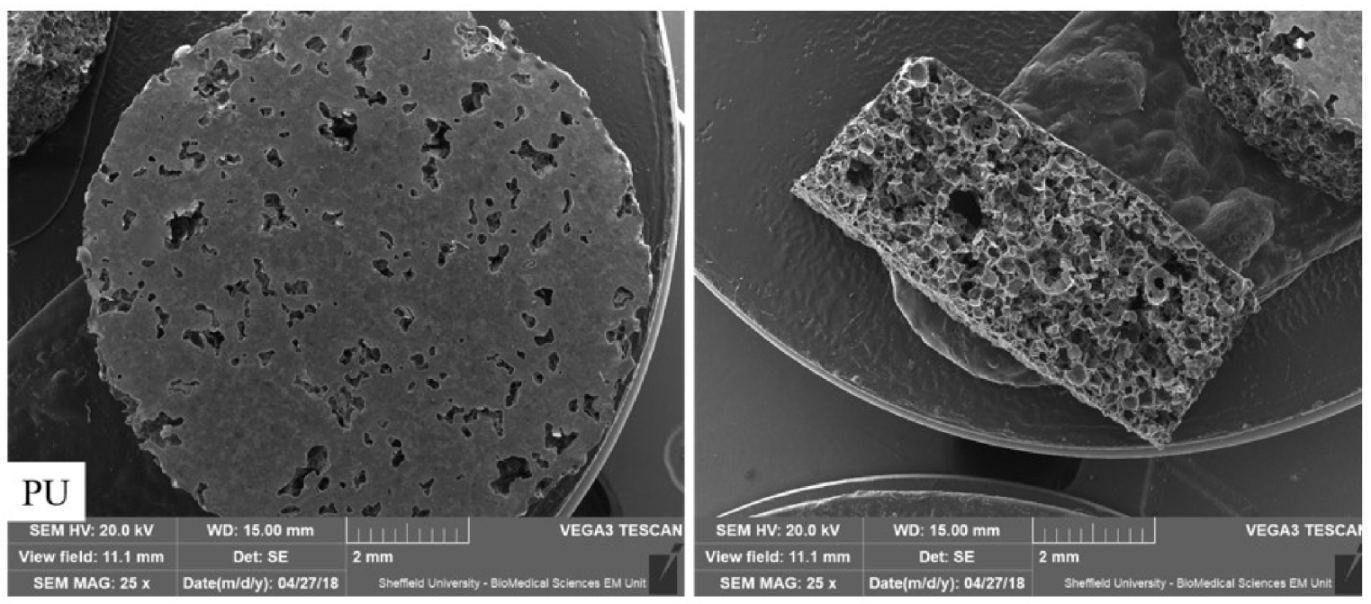
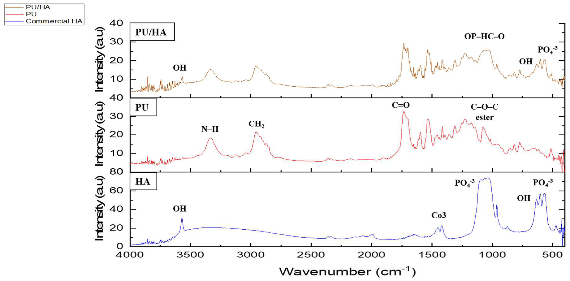
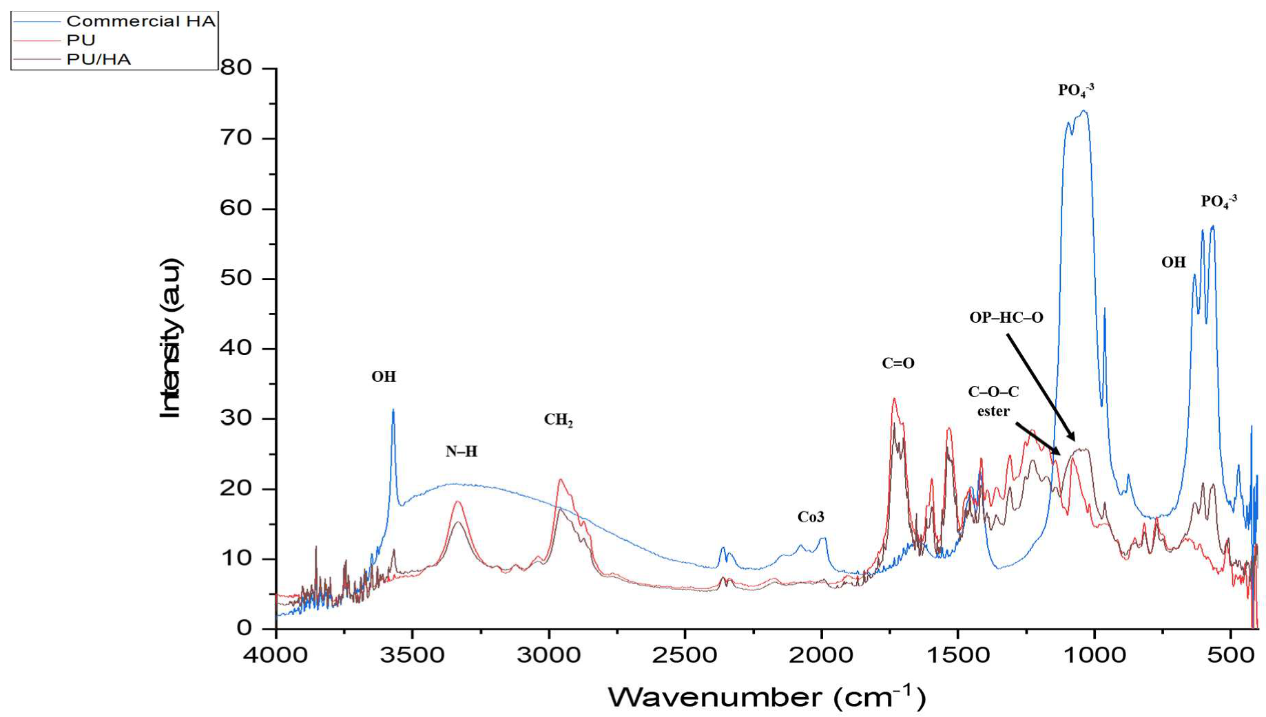
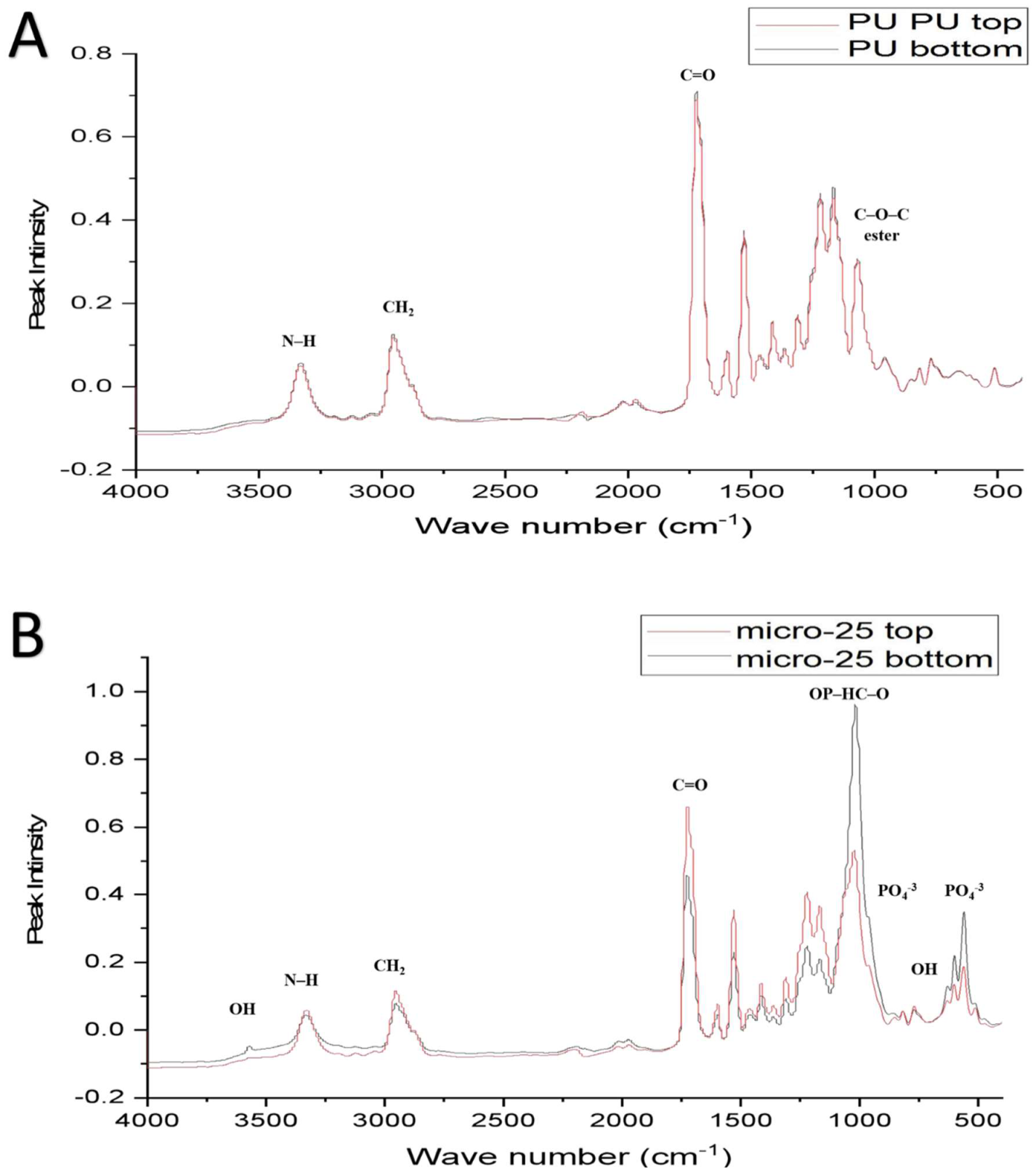
2.1. PU and PU/HA Scaffolds
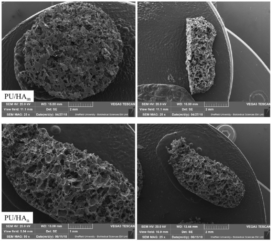
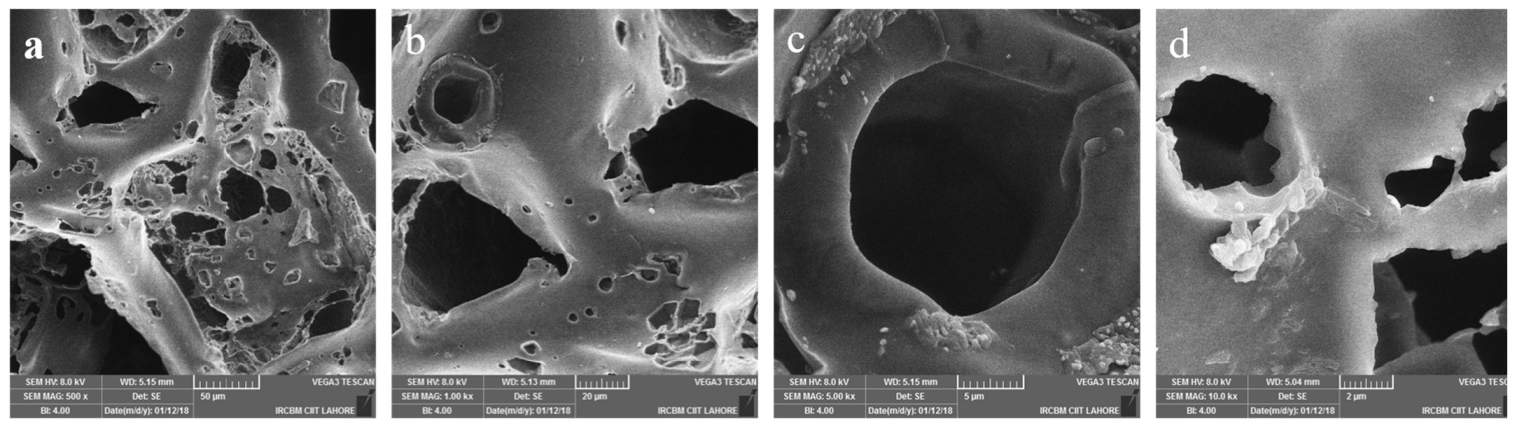
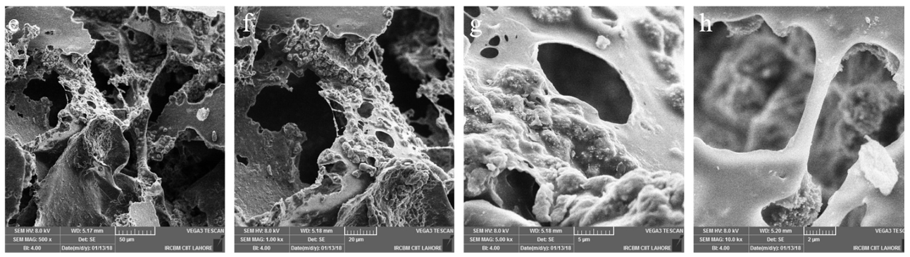
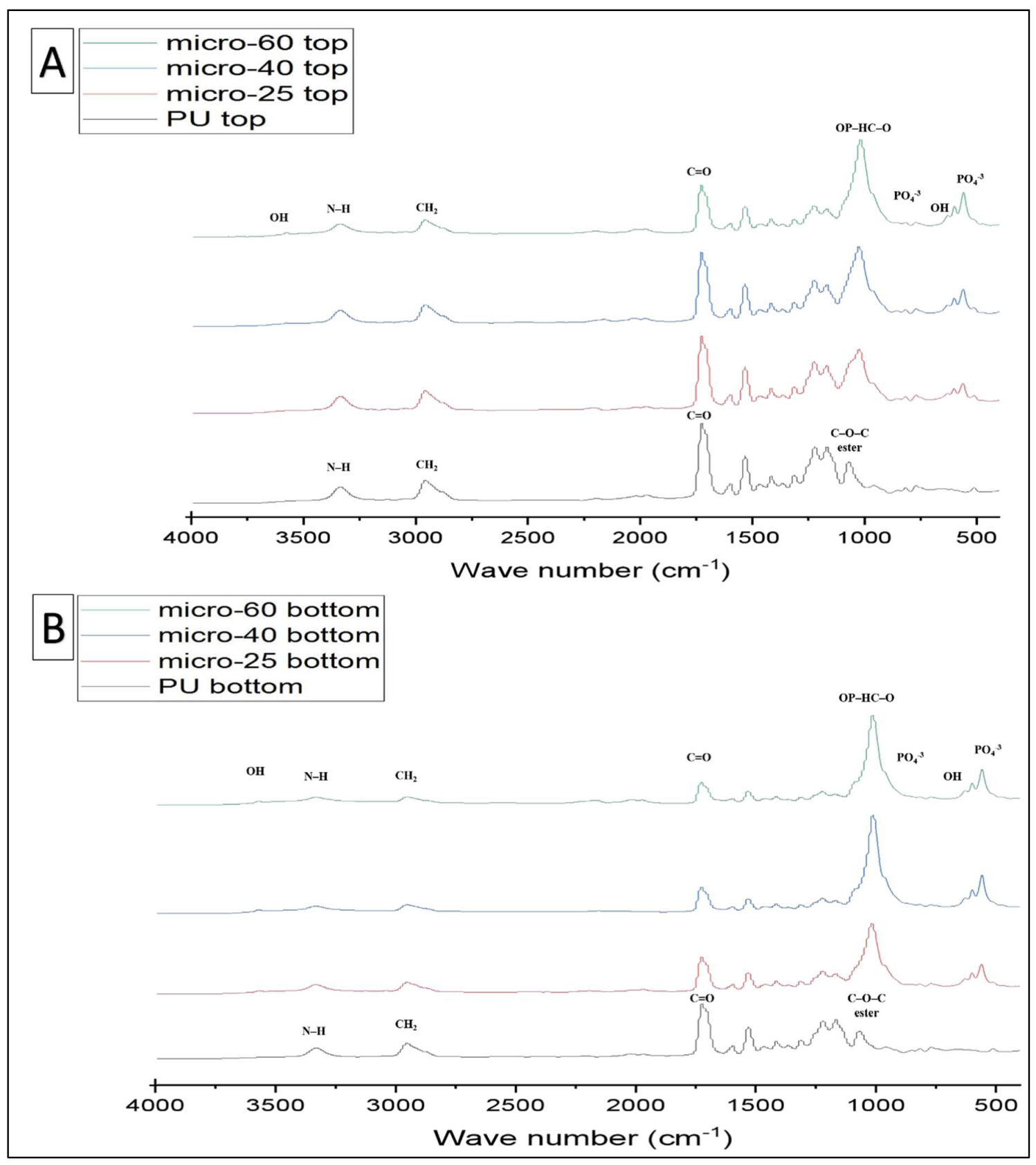
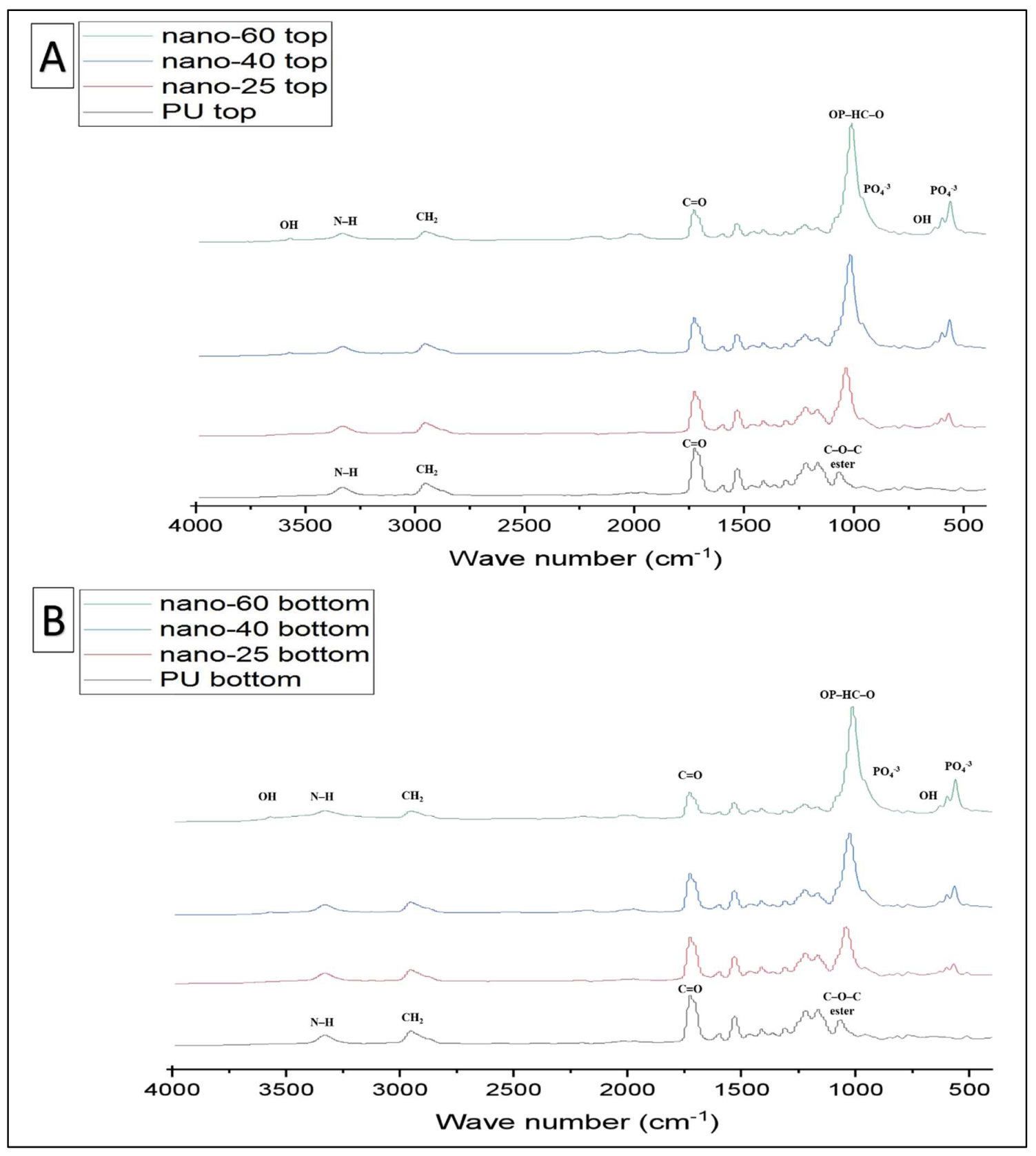
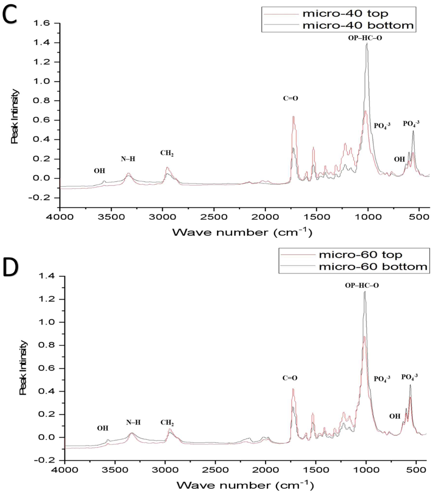
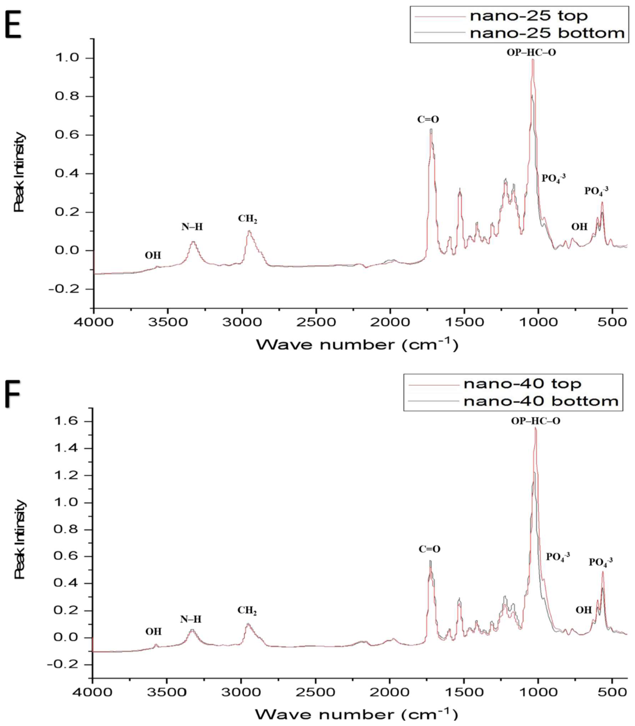
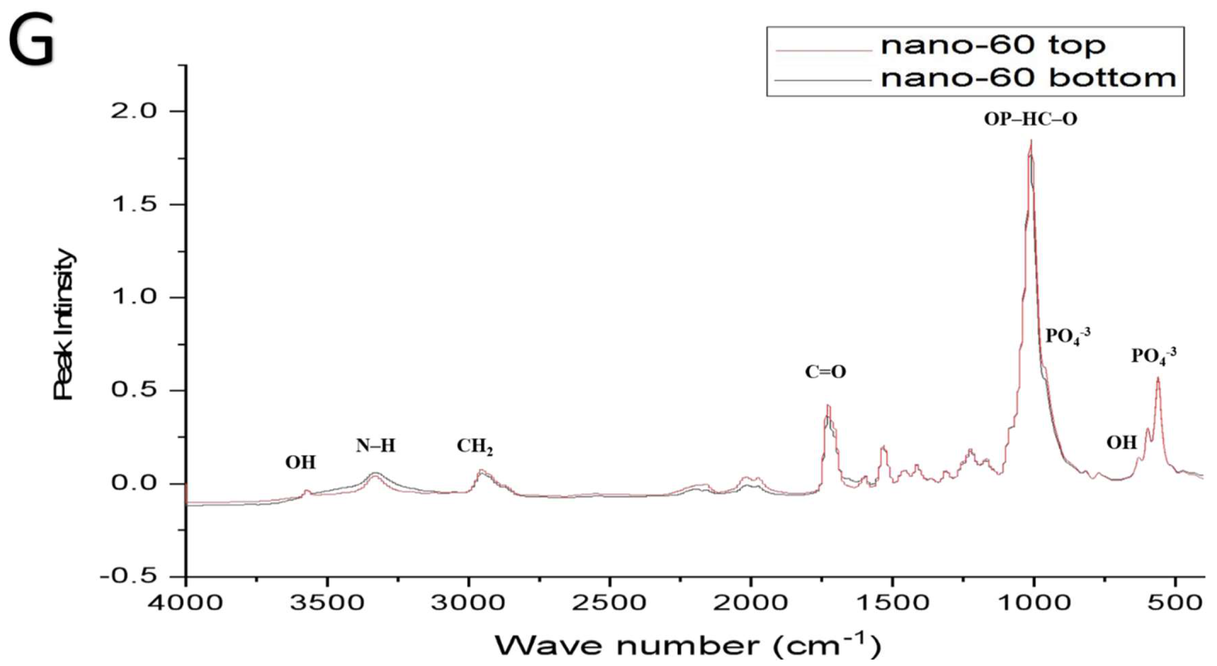
2.2. PU, PU/HAmicro and PU/HAnano Scaffolds
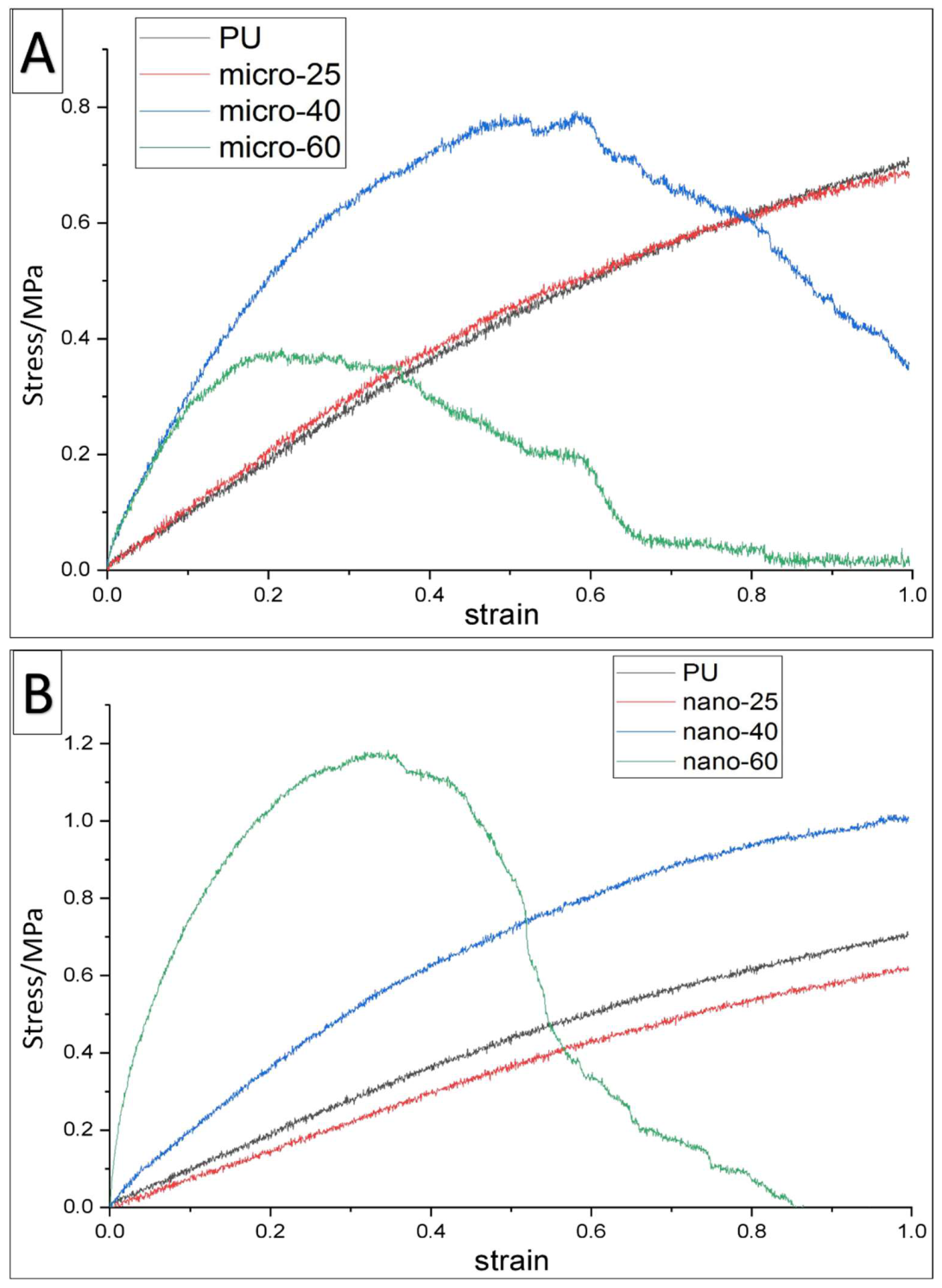
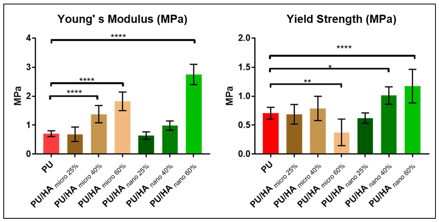
2.3. Mechanical Properties
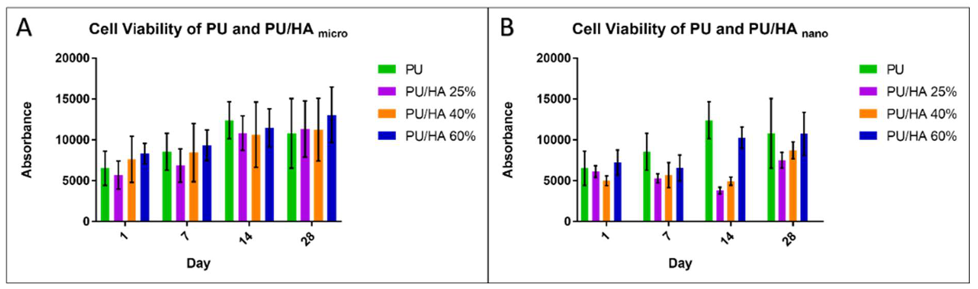
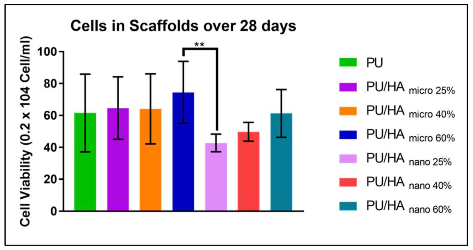
2.4. Cell Viability
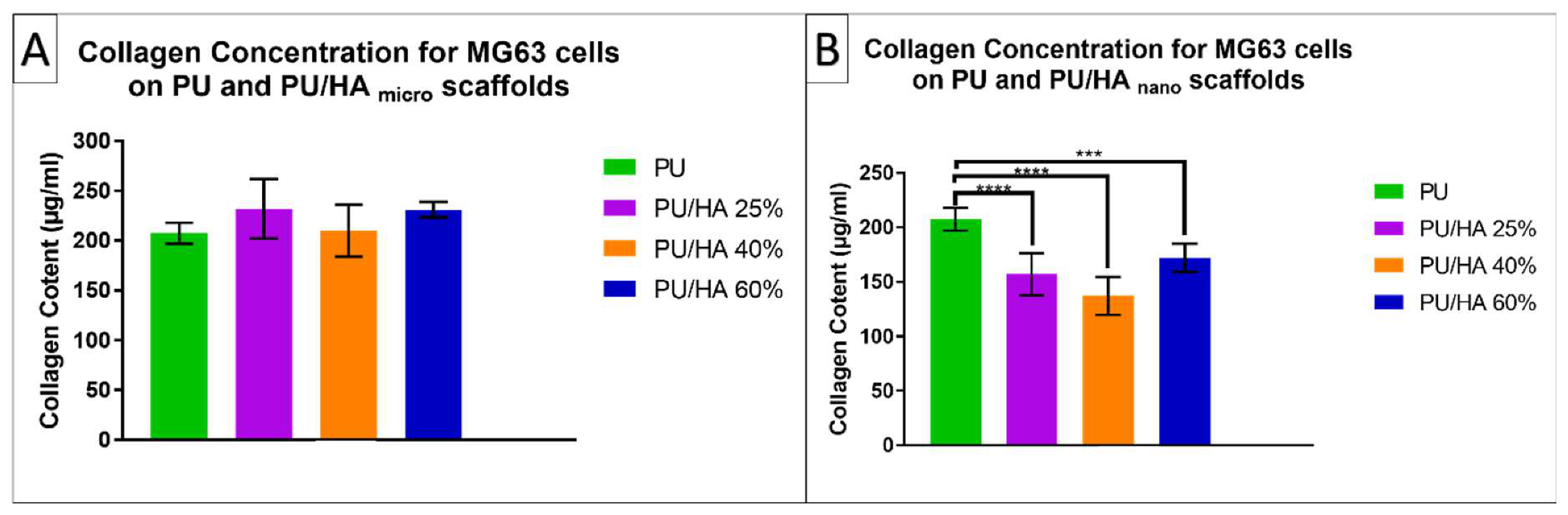
2.5. Collagen
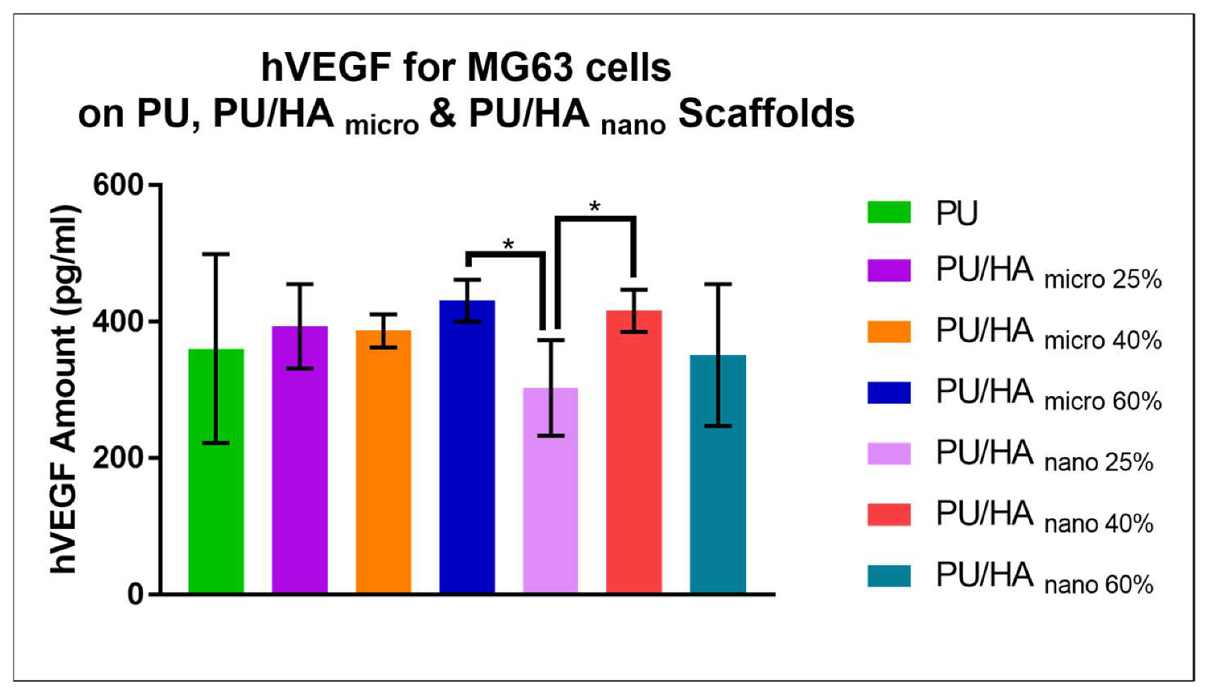
2.6. Vascular Endothelial Growth Factor (VEGF) Assay
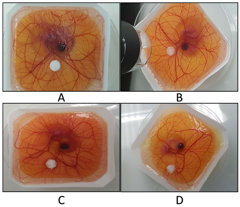
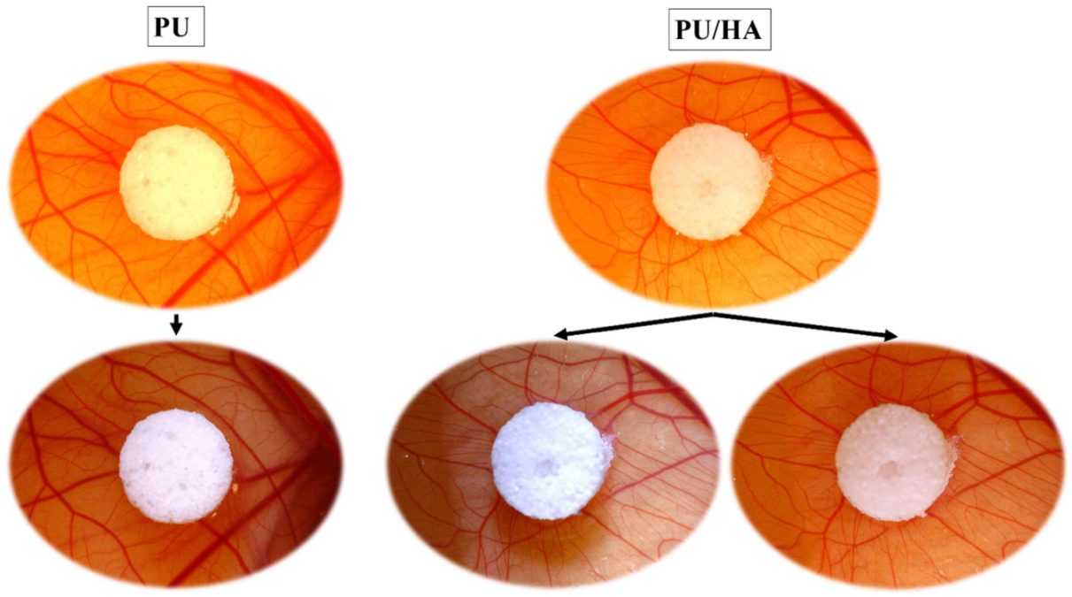
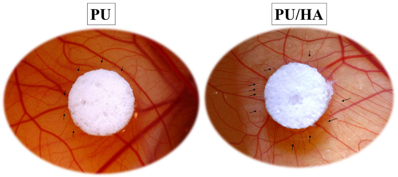
2.7. Ex-Ovo Chick Chorioallantoic Membrane (CAM) Assay
3. Discussion
4. Materials and Methods
4.1. Materials
4.2. PU Solution
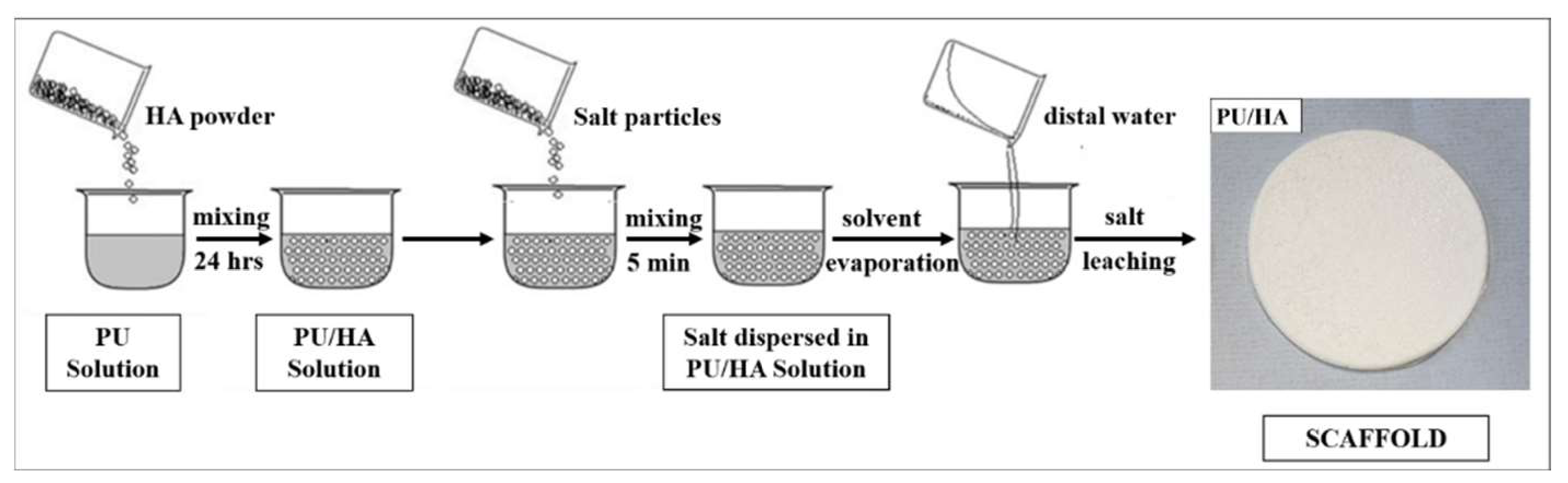
4.3. PU/HA Solution
4.4. Preparation of Salt Particles
4.5. Cast Solvent/Particles Leaching PU and PU/HA Scaffolds
4.6. Peaparation of Scaffolds for Charactrisation
4.7. Scanning Electron Microscopy (SEM)
4.8. Fourier Transform Infrared Spectroscopy (FTIR)
4.9. Mechanical Test: Tensile Test
4.10. Culture Conditions for Human Osteoblast Cell Line MG63
4.11. Prepare and Sterilise Scaffolds
4.12. Cell Seeding
4.13. Alamar Blue Cell Viability
4.14. Vascular Endothelial Growth Factor (VEGF) Assay
4.15. Chick Chorioallontoic Membrane Assay (CAM Assay)
4.16. Scaffold Sterilising and Implanting
4.17. Statistical Analysis
5. Conclusions
Author Contributions
Funding
Acknowledgments
Conflicts of Interest
Abbreviations
| FTIR | Fourier transform infrared |
| ATR | Attenuated Total Reflectance |
| PU | Polyurethane |
| HA | Hydroxyapatite |
| CAM | Chick Chorioallantoic Membrane |
| SEM | Scanning Electron Microscopy |
| VEGF | Vascular Endothelial Growth Factor |
References
- Dubois, L.; Steenen, S.A.; Gooris, P.J.J.; Mourits, M.P.; Becking, A.G. Controversies in orbital reconstruction—II. Timing of post-traumatic orbital reconstruction: A systematic review. Int. J. Oral Maxillofac. Surg. 2015, 44, 433–440. [Google Scholar] [CrossRef] [PubMed]
- Kanno, T.; Tatsumi, H.; Karino, M.; Yoshino, A.; Koike, T.; Ide, T.; Sekine, J. Applicability of an Unsintered Hydroxyapatite Particles/Poly-L-Lactide Composite Sheet with Tack Fixation for Orbital Fracture Reconstruction. J. Hard Tissue Biol. 2016, 25, 329–334. [Google Scholar] [CrossRef]
- Malda, J.; Rouwkema, J.; Martens, D.E.; le Comte, E.P.; Kooy, F.K.; Tramper, J.; van Blitterswijk, C.; Riesle, J. Oxygen gradients in tissue-engineered Pegt/Pbt cartilaginous constructs: Measurement and modeling. Biotechnol. Bioeng. 2004, 86, 9–18. [Google Scholar] [CrossRef] [PubMed]
- Bramfeld, H.; Sabra, G.; Centis, V.; Vermette, P. Scaffold vascularization: A challenge for three-dimensional tissue engineering. Curr. Med. Chem. 2010, 17, 3944–3967. [Google Scholar] [CrossRef]
- Rouwkema, J.; Rivron, N.C.; van Blitterswijk, C.A. Vascularization in tissue engineering. Trends Biotechnol. 2008, 26, 434–441. [Google Scholar] [CrossRef]
- Vo, T.N.; Kasper, F.K.; Mikos, A.G. Strategies for controlled delivery of growth factors and cells for bone regeneration. Adv. Drug Deliv. Rev. 2012, 64, 1292–1309. [Google Scholar] [CrossRef]
- Butscher, A.; Bohner, M.; Hofmann, S.; Gauckler, L.; Müller, R. Structural and material approaches to bone tissue engineering in powder-based three-dimensional printing. Acta Biomater. 2011, 7, 907–920. [Google Scholar] [CrossRef]
- Gong, T.; Xie, J.; Liao, J.; Zhang, T.; Lin, S.; Lin, Y. Nanomaterials and bone regeneration. Bone Res. 2015, 3, 15029. [Google Scholar] [CrossRef]
- Gorna, K.; Gogolewski, S. Preparation, degradation, and calcification of biodegradable polyurethane foams for bone graft substitutes. J. Biomed. Mater. Res. 2003, 67, 813–827. [Google Scholar] [CrossRef]
- Gorna, K.; Gogolewski, S. Biodegradable porous polyurethane scaffolds for tissue repair and regeneration. J. Biomed. Mater. Res. Part A 2006, 79, 128–138. [Google Scholar] [CrossRef]
- Heijkants, R.G.J.C.; Van Tienen, T.G.; De Groot, J.H.; Pennings, A.J.; Buma, P.; Veth, R.P.H.; Schouten, A.J. Preparation of a polyurethane scaffold for tissue engineering made by a combination of salt leaching and freeze-drying of dioxane. J. Mater. Sci. 2006, 41, 2423–2428. [Google Scholar] [CrossRef]
- Tsui, Y.K.; Gogolewski, S. Microporous biodegradable polyurethane membranes for tissue engineering. J. Mater. Sci. Mater. Med. 2009, 20, 1729–1741. [Google Scholar] [CrossRef]
- Zhu, Q.X.; Li, Y.M.; Han, D. Co-substitution of carbonate and fluoride in hydroxyapatite: Effect on substitution type and content. Front. Mater. Sci. 2015, 9, 192–198. [Google Scholar] [CrossRef]
- Barry, A.B.; Zhuang, H.; Baig, A.A.; Higuchi, W.I. Effect of fluoride pretreatment on the solubility of synthetic carbonated apatite. Calcif. Tissue Res. 2003, 72, 236–242. [Google Scholar] [CrossRef]
- Verma, G.; Barick, K.C.; Shetake, N.G.; Pandey, B.N.; Hassan, P.A. Citrate-functionalized hydroxyapatite nanoparticles for pH-responsive drug delivery. RSC Adv. 2016, 6, 77968–77976. [Google Scholar] [CrossRef]
- Khan, A.S.; Aamer, S.; Chaudhry, A.A.; Wong, F.S.L.; Rehman, I.U. Synthesis and characterizations of a fluoride-releasing dental restorative material. Mater. Sci. Eng. C 2013, 33, 3458–3464. [Google Scholar] [CrossRef] [PubMed]
- Da Mota, M.; De, V.; Branco, A. Polyurethane-Based Scaffolds for Bone Tissue Regeneration. Ph.D. Thesis, Instituto Superior Técnico, Lisbon, Portugal, 2015. Volume 1. pp. 1–10. [Google Scholar]
- Qidwai, M.; Sheraz, M.A.; Ahmed, S.; Alkhuraif, A.A.; Ur Rehman, I. Preparation and characterization of bioactive composites and fibers for dental applications. Dent. Mater. 2014, 30, e253–e263. [Google Scholar] [CrossRef]
- Khan, A.S.; Ahmed, Z.; Edirisinghe, M.J.; Wong, F.S.L.; Rehman, I.U. Preparation and characterization of a novel bioactive restorative composite based on covalently coupled polyurethane-nanohydroxyapatite fibres. Acta Biomater. 2008, 4, 1275–1287. [Google Scholar] [CrossRef]
- Iqbal, N.; Khan, A.S.; Asif, A.; Yar, M.; Haycock, J.W.; Rehman, I.U. Recent concepts in biodegradable polymers for tissue engineering paradigms: A critical review. Int. Mater. Rev. 2018, 64, 91–126. [Google Scholar] [CrossRef]
- Kocak, F.Z.; Talari, A.C.S.; Yar, M.; Rehman, I.U. In-situ forming ph and thermosensitive injectable hydrogels to stimulate angiogenesis: Potential candidates for fast bone regeneration applications. Int. J. Mol. Sci. 2020, 21, 1633. [Google Scholar] [CrossRef] [Green Version]
- Kocak, F.Z.; Yar, M.; Rehman, I.U. Investigation of different synthesis parameters of hydroxyapatite for tissue engineering applications. 2022. [Google Scholar]
- Kocak, F.Z.; Yar, M.; Rehman, I.U. Hydroxyapatite-Integrated, Heparin-and Glycerol-Functionalized Chitosan-Based Injectable Hydrogels with Improved Mechanical and Proangiogenic Performance. Int. J. Mol. Sci. 2022, 23, 5370. [Google Scholar] [CrossRef]
- Liu, H.; Peng, H.; Wu, Y.; Zhang, C.; Cai, Y.; Xu, G.; Li, Q.; Chen, X.; Ji, J.; Zhang, Y.; et al. The promotion of bone regeneration by nanofibrous hydroxyapatite/chitosan scaffolds by effects on integrin-BMP/Smad signaling pathway in BMSCs. Biomaterials 2013, 34, 4404–4417. [Google Scholar] [CrossRef]
- Im, O.; Li, J.; Wang, M.; Zhang, L.G.; Keidar, M. Biomimetic three-dimensional nanocrystalline hydroxyapatite and magnetically synthesized single-walled carbon nanotube chitosan nanocomposite for bone regeneration. Int. J. Nanomed. 2012, 7, 2087–2099. [Google Scholar]
- Chaudhry, A.A.; Khalid, H.; Zahid, M.; Ijaz, K.; Akhtar, H.; Younas, B.; Manzoor, F.; Iqbal, F.; Rehman, I.U. Zinc containing calcium phosphates obtained via microwave irradiation of suspensions. Mater. Chem. Phys. 2022, 276, 124921. [Google Scholar] [CrossRef]
- Liu, Q.; De Wijn, J.R.; Bakker, D.; Van Blitterswijk, C.A. Surface modification of hydroxyapatite to introduce interfacial bonding with Polyactive® 70/30 in a biodegradable composite. J. Mater. Sci. Mater. Med. 1996, 7, 551–557. [Google Scholar] [CrossRef]
- Dong, G.-C.; Sun, J.-S.; Yao, C.-H.; Jiang, G.J.; Huang, C.-W.; Lin, F.-H. A study on grafting and characterization of HMDI-modified calcium hydrogenphosphate. Biomaterials 2001, 22, 3179–3189. [Google Scholar] [CrossRef]
- Alhamoudi, F.H.; Akhtar, H.; Almoshawah, Y.; Talari, A.C.; Chaudhry, A.A.; Reilly, G.C.; Rehman, I.U. Bioactive Nano Hydroxyapatites for Orbital Floor Repair and Regeneration. J. Nanomed. 2021, 4, 1038. [Google Scholar]
- Rehman, I.U. Biodegradable Polyurethanes: Biodegradable Low Adherence Films for the Prevention of Adhesions after Surgery. J. Biomater. Appl. 1996, 11, 182–257. [Google Scholar] [CrossRef]
- Tetteh, G.; Khan, A.S.; Reilly, G.C.; Rehman, I.U. Electrospun polyurethane/hydroxyapatite bioactive Scaffolds for bone tissue engineering: The role of solvent and hydroxyapatite particles $. J. Mech. Behav. Biomed. Mater. 2014, 39, 95–110. [Google Scholar] [CrossRef]
- Rehman, I.; Bonfield, W. Characterization of hydroxyapatite and carbonated apatite by photo acoustic FTIR spectroscopy. J. Mater. Sci. Mater. Med. 1997, 8, 1–4. [Google Scholar] [CrossRef]
- Khan, A.F.; Awais, M.; Khan, A.S.; Tabassum, S.; Chaudhry, A.A.; Rehman, I.U. Raman spectroscopy of natural bone and synthetic apatites. Appl. Spectrosc. Rev. 2013, 48, 329–355. [Google Scholar] [CrossRef]
- Bose, S.; Roy, M.; Bandyopadhyay, A. Recent advances in bone tissue engineering scaffolds. Trends Biotechnol. 2012, 30, 546–554. [Google Scholar] [CrossRef] [Green Version]
- Klawitter, J.J.; Hulbert, S.F. Application of porous ceramics for the attachment of load bearing internal orthopedic applications. J. Biomed. Mater. Res. 1971, 5, 161–229. [Google Scholar] [CrossRef]
- Woodard, J.R.; Hilldore, A.J.; Lan, S.K.; Park, C.J.; Morgan, A.W.; Eurell, J.A.; Clark, S.G.; Wheeler, M.B.; Jamison, R.D.; Johnson, A.J. The mechanical properties and osteoconductivity of hydroxyapatite bone scaffolds with multi-scale porosity. Biomaterials 2007, 28, 45–54. [Google Scholar] [CrossRef] [PubMed]
- Yang, W.; Both, S.K.; Zuo, Y.; Birgani, Z.T.; Habibovic, P.; Li, Y.; Jansen, J.A.; Yang, F. Biological evaluation of porous aliphatic polyurethane/hydroxyapatite composite scaffolds for bone tissue engineering. J. Biomed. Mater. Res. Part A 2015, 103, 2251–2259. [Google Scholar] [CrossRef] [PubMed]
- Rezwan, K.; Chen, Q.Z.; Blaker, J.J.; Boccaccini, A.R. Biodegradable and bioactive porous polymer/inorganic composite scaffolds for bone tissue engineering. Biomaterials 2006, 27, 3413–3431. [Google Scholar] [CrossRef] [PubMed]
- Wang, L.; Li, Y.; Zuo, Y.; Zhang, L.; Zou, Q.; Cheng, L.; Jiang, H. Porous bioactive scaffold of aliphatic polyurethane and hydroxyapatite for tissue regeneration. Biomed. Mater. 2009, 4, 025003. [Google Scholar] [CrossRef]
- Zhu, Q.; Li, X.; Fan, Z.; Xu, Y.; Niu, H.; Li, C.; Dang, Y.; Huang, Z.; Wang, Y.; Guan, J. Biomimetic polyurethane/TiO2 nanocomposite scaffolds capable of promoting biomineralization and mesenchymal stem cell proliferation. Mater. Sci. Eng. C 2018, 85, 79–87. [Google Scholar] [CrossRef]
- Liu, H.; Zhang, L.; Zuo, Y.; Wang, L.; Huang, D.; Shen, J.; Shi, P.; Li, Y. Preparation and characterization of aliphatic polyurethane and hydroxyapatite composite scaffold. J. Appl. Polym. Sci. 2009, 112, 2968–2975. [Google Scholar] [CrossRef]
- Ho, S.T.; Hutmacher, D.W. A comparison of micro CT with other techniques used in the characterization of scaffolds. Biomaterials 2006, 27, 1362–1376. [Google Scholar] [CrossRef]
- Kordani, N.; Asadi, A.; Jabbari, A. Optimization of fracture behavior of alumina/silicon carbide nano ceramic. Neural Comput. Appl. 2012, 23, 2379–2385. [Google Scholar] [CrossRef]
- Hassan, M.; Sulaiman, M.; Yuvaraju, P.D.; Galiwango, E.; Rehman, I.U.; Al-Marzouqi, A.H.; Khaleel, A.; Mohsin, S. Biomimetic PLGA/Strontium-Zinc Nano Hydroxyapatite Composite Scaffolds for Bone Regeneration. J. Funct. Biomater. 2022, 13, 13. [Google Scholar] [CrossRef]
- Patel, N.; Best, S.M.; Bonfield, W.; Gibson, I.R.; Hing, K.A.; Damien, E.; Revell, P.A. A comparative study on the in vivo behavior of hydroxyapatite and silicon substituted hydroxyapatite granules. J. Mater. Sci. Mater. Med. 2002, 13, 1199–1206. [Google Scholar] [CrossRef]
- Bonzani, I.C.; Adhikari, R.; Houshyar, S.; Mayadunne, R.; Gunatillake, P.; Stevens, M.M. Synthesis of two-component injectable polyurethanes for bone tissue engineering. Biomaterials 2007, 28, 423–433. [Google Scholar] [CrossRef]
- Laschke, M.W.; Strohe, A.; Menger, M.D.; Alini, M.; Eglin, D. In vitro and in vivo evaluation of a novel nanosize hydroxyapatite particles/poly (ester-urethane) composite scaffold for bone tissue engineering. Acta Biomater. 2010, 6, 2020–2027. [Google Scholar] [CrossRef]
- Kavlock, K.D.; Pechar, T.W.; Hollinger, J.O.; Guelcher, S.A.; Goldstein, A.S. Synthesis and characterization of segmented poly (esterurethane urea) elastomers for bone tissue engineering. Acta Biomater. 2007, 3, 475–484. [Google Scholar] [CrossRef]
- Du, J.J.; Zuo, Y.; Zou, Q.; Sun, B.; Zhou, M.B.; Li, L.M.; Man, Y.; Li, Y.B. Preparation and in vitro evaluation of polyurethane composite scaffolds based on glycerol esterified castor oil and hydroxyapatite. Mater. Res. Innov. 2013, 18, 160–168. [Google Scholar] [CrossRef]
- Popescu, L.M.; Piticescu, R.M.; Antonelli, A.; Rusti, C.F.; Carboni, E.; Sfara, C.; Magnani, M.; Badilita, V.; Vasile, E.; Trusca, R.; et al. Recent advances in synthesis, characterization of hydroxyapatite/polyurethane composites and study of their biocompatible properties. J. Mater. Sci. Mater. Electron. 2013, 24, 2491–2503. [Google Scholar] [CrossRef]
- Nathanael, A.J.; Mangalaraj, D.; Hong, S.I.; Masuda, Y.; Rhee, Y.H.; Kim, H.W. In fl uence of fl uorine substitution on the morphology and structure of hydroxyapatite nanocrystals prepared by hydrothermal method. Mater. Chem. Phys. 2013, 137, 967–976. [Google Scholar] [CrossRef]
- Li, B.; Liao, X.; Zheng, L.; He, H.; Wang, H.; Fan, H.; Zhang, X. Preparation and cellular response of porous A-type carbonated hydroxyapatite nanoceramics. Mater. Sci. Eng. C 2012, 32, 929–936. [Google Scholar] [CrossRef]
- Ismail, Y.M.B.; Wimpenny, I.; Bretcanu, O. In Vitro Biocompatibility of SiCHA Nanopowders on Human Mesenchymal Stem Cells. J. Eng. Sci. 2018, 14, 35–46. [Google Scholar] [CrossRef]
- Nasker, P.; Mukherjee, M.; Kant, S.; Tripathy, S.; Sinha, A. Fluorine substituted nano hydroxyapatite: Synthesis, bio-activity and antibacterial response study. Ceram. Int. 2018, 44, 22008–22013. [Google Scholar] [CrossRef]
- Nasker, P.; Samanta, A.; Rudra, S.; Sinha, A.; Mukhopadhyay, A.K.; Das, M. Journal of the Mechanical Behavior of Biomedical Materials E ff ect of fl uorine substitution on sintering behaviour, mechanical and bioactivity of hydroxyapatite. J. Mech. Behav. Biomed. Mater. 2019, 95, 136–142. [Google Scholar] [CrossRef]
- Fernandes, M.H.; Alves, M.M.; Cebotarenco, M.; Ribeiro, I.A.C. Materials Science & Engineering C Citrate zinc hydroxyapatite nanorods with enhanced cytocompatibility and osteogenesis for bone regeneration. Mater. Sci. Eng. C 2020, 115, 111147. [Google Scholar]
- Shahzadi, L.; Yar, M.; Jamal, A.; Siddiqi, S.A.; Chaudhry, A.A.; Zahid, S.; Tariq, M.; Rehman, I.U.; MacNeil, S. Triethyl orthoformate covalently cross-linked chitosan-(poly vinyl) alcohol based biodegradable scaffolds with heparin-binding ability for promoting neovascularisation. J. Biomater. Appl. 2016, 31, 582–593. [Google Scholar] [CrossRef]
- Yar, M.; Gigliobianco, G.; Shahzadi, L.; Dew, L.; Siddiqi, S.A.; Khan, A.F.; Chaudhry, A.A.; Rehman, I.U.; MacNeil, S. Production of chitosan PVA PCL hydrogels to bind heparin and induce angiogenesis. Int. J. Polym. Mater. Polym. Biomater. 2015, 65, 466–476. [Google Scholar] [CrossRef]
- Leach, J.K.; Kaigler, D.; Wang, Z.; Krebsbach, P.H.; Mooney, D.J. Coating of VEGF-releasing scaffolds with bioactive glass for angiogenesis and bone regeneration. Biomaterials 2006, 27, 3249–3255. [Google Scholar]
- Kaigler, D.; Wang, Z.; Horger, K.; Mooney, D.J.; Krebsbach, P.H. VEGF scaffolds enhance angiogenesis and bone regeneration in irradiated osseous defects. J. Bone Miner. Res. 2006, 21, 735–744. [Google Scholar] [CrossRef]
- Kannan, R.Y.; Salacinski, H.J.; Sales, K.; Butler, P.; Seifalian, A.M. The roles of tissue engineering and vascularisation in the development of micro-vascular networks: A review. Biomaterials 2005, 26, 1857–1875. [Google Scholar] [CrossRef] [PubMed]
- Janik, H.; Marzec, M. A review: Fabrication of porous polyurethane scaffolds. Mater. Sci. Eng. C 2015, 48, 586–591. [Google Scholar] [CrossRef] [PubMed]
- Eke, G.; Mangir, N.; Hasirci, N.; Macneil, S.; Hasirci, V. Biomaterials Development of a UV crosslinked biodegradable hydrogel containing adipose derived stem cells to promote vascularization for skin wounds and tissue engineering. Biomaterials 2017, 129, 188–198. [Google Scholar] [CrossRef] [PubMed]


| Functional Groups | PU Scaffolds Wavenumbers cm−1 | PU/HA Scaffolds Wavenumbers cm−1 |
|---|---|---|
| O–H (stretching) | 3570 | |
| Free N–H | 3440, 3451 | |
| Bonded N–H (stretching) (linkage of isocyanate and soft segment, known as urethane linkage) | 3330 | 3330 |
| C–H Aromatic region | 3121, 3039, 3031 | 3121 |
| N–H–C=O Linkage of OH, (HA) and NCO (PU) covalent bonding | 3313 | |
| CH2 (Polyester), stretching vibration | 2930–2800 | |
| C–H band of (-CH2-) Present at a number of positions due to the presence of different (-CH2-) group in polymer chain | 2958, 2885, 2796, | 2930–2800 |
| C–H band of (-CH2-), Chain extender | 817, 772 | 817, 772 |
| C–H aromatic regions | 3122, 3101 | |
| C–C aromatic ring breathings of (MDI) | 1597, 1417, 517 | |
| C=O hydrogen bonded secondary amide absorption bands | 1750–1650, 1716 1734–1616 | 1710, 1716 1734–1616 |
| C=O free (non-bonded), peak position changes due to the change in the soft segment | 1734 1733–1728 | 1730 1734 |
| N–H + C–N stretching | 1540, 1232, 1224 | 1540, 1232, 1224 |
| O–C–O + N–H (urethane linkage) interactions/bonding with phosphate groups, also causes a shift to the carbonyl absorption band, shifting it to a higher wavenumber | 1716 | 1719 |
| N–H + C–N, amide II | 1540 | 1540 |
| C–C, symmetric stretch, aromatic ring of MDI | 1417 | 1417 |
| N–H + C–N, symmetric stretch | 1311, 1232 | 1311, 1232 |
| C–O–C, ester linkage | 1081, 1065 | 1081, 1085 |
| C–H, aromatic ring breathings | 1473, 1457,1019 | |
| O–P–O, Phosphate | 1074, 962, 603, 566 | |
| C–C, aromatic unsymmetric stretch | 817, 517 | 817 |
| Name | DMF (wt%) | PU:HA (wt) | Micro-HA (%) | Nano-HA (%) |
|---|---|---|---|---|
| PU | 100 | 4:0 | 0 | 0 |
| Micro-25 | 100 | 3:1 | 25 | 0 |
| Micro-40 | 100 | 2.4:1.6 | 40 | 0 |
| Micro-60 | 100 | 1.6:2.4 | 60 | 0 |
| Nano-25 | 100 | 3:1 | 0 | 25 |
| Nano-40 | 100 | 2.4:1.6 | 0 | 40 |
| Nano-60 | 100 | 1.6:2.4 | 0 | 60 |
Publisher’s Note: MDPI stays neutral with regard to jurisdictional claims in published maps and institutional affiliations. |
© 2022 by the authors. Licensee MDPI, Basel, Switzerland. This article is an open access article distributed under the terms and conditions of the Creative Commons Attribution (CC BY) license (https://creativecommons.org/licenses/by/4.0/).
Share and Cite
AL-Hamoudi, F.; Rehman, H.U.; Almoshawah, Y.A.; Talari, A.C.S.; Chaudhry, A.A.; Reilly, G.C.; Rehman, I.U. Bioactive Composite for Orbital Floor Repair and Regeneration. Int. J. Mol. Sci. 2022, 23, 10333. https://0-doi-org.brum.beds.ac.uk/10.3390/ijms231810333
AL-Hamoudi F, Rehman HU, Almoshawah YA, Talari ACS, Chaudhry AA, Reilly GC, Rehman IU. Bioactive Composite for Orbital Floor Repair and Regeneration. International Journal of Molecular Sciences. 2022; 23(18):10333. https://0-doi-org.brum.beds.ac.uk/10.3390/ijms231810333
Chicago/Turabian StyleAL-Hamoudi, Fahad, Hamza U. Rehman, Yasir A. Almoshawah, Abdullah C. S. Talari, Aqif A. Chaudhry, Gwendolen C. Reilly, and Ihtesham U. Rehman. 2022. "Bioactive Composite for Orbital Floor Repair and Regeneration" International Journal of Molecular Sciences 23, no. 18: 10333. https://0-doi-org.brum.beds.ac.uk/10.3390/ijms231810333