Development of an Electrohydraulic Variable Buoyancy System


1
LAETA-INEGI, Faculdade de Engenharia, Universidade do Porto, Rua Dr. Roberto Frias, s/n, 4200-465 Porto, Portugal
2
LAETA-INEGI, Universidade do Porto, Rua Dr. Roberto Frias, s/n, 4200-465 Porto, Portugal
3
INESC-TEC, Faculdade de Engenharia, Universidade do Porto, Rua Dr. Roberto Frias, s/n, 4200-465 Porto, Portugal
*
Author to whom correspondence should be addressed.
Information 2019, 10(12), 396; https://0-doi-org.brum.beds.ac.uk/10.3390/info10120396
Submission received: 26 November 2019
/
Revised: 12 December 2019
/
Accepted: 13 December 2019
/
Published: 17 December 2019
(This article belongs to the Special Issue Online Experimentation and the IoE)
Abstract
:The growing needs in exploring ocean resources have been pushing the length and complexity of autonomous underwater vehicle (AUV) missions, leading to more stringent energy requirements. A promising approach to reduce the energy consumption of AUVs is to use variable buoyancy systems (VBSs) as a replacement or complement to thruster action, since VBSs only require energy consumption during limited periods of time to control the vehicle’s floatation. This paper presents the development of an electrohydraulic VBS to be included in an existing AUV for shallow depths of up to 100 m. The device’s preliminary mechanical design is presented, and a mathematical model of the device’s power consumption is developed, based on data provided by the manufacturer. Taking a standard mission profile as an example, a comparison between the energy consumed using thrusters and the designed VBS is presented and compared.
1. Introduction
In recent years, autonomous underwater vehicles have experienced steady development as a result of rising interest in the knowledge of ocean state variables. This knowledge is key for fishing, weather forecasting, and underwater mining, among other activities. One of the main aspects to consider when designing such vehicles is their energetic autonomy, as it strongly restricts mission length and complexity. The major energy consumption source for AUVs is their propulsion and, as such, it is expected that by controlling the vehicles floatation, energetic improvements should be achieved, since energy is only spent during small periods of time. This is the principle used in underwater gliders [1] with their variable buoyancy systems (VBSs), enabling them to complete month-long missions without any type of maintenance.
Several kinds of solutions for VBSs can be found in literature, however, electromechanical [2,3] and electrohydraulic [4,5,6] solutions are the most common. Purely electrical solutions tend to be more efficient for shallow depths, since the required forces are lower. Electrohydraulic solutions, on the other hand, are usually more efficient for higher pressures, making them particularly suited for deep water applications. A comparison between these two solutions is made in [7].
Several studies regarding electrohydraulic VBSs can be found in the literature. For instance, in [4], an oil hydraulic system comprised of a pump, driving motor, valves, and external and internal reservoir for the depth control of an underwater glider is described. The device is able to descend as far as 2100 m and efficiency values from 42% to 45% have been recorded for pressures higher than 100 bar. Unfortunately, for low pressures, the efficiency drops, possibly due to mechanical friction losses, for instance, an efficiency of 10% was recorded for a 6-bar pressure.
The vehicle proposed in [5] has a VBS consisting of an electric motor, mechanical transmission, piston, three-way valve, internal reservoir, and an external bladder. Given the pump’s maximum pressure of 350 bar, this device can reach much higher depths than the one developed in [4], which is conceptually similar. Efficiency values from 12% up to 43% were reported at pressures ranging from 2 to 35 MPa, respectively. However, this solution is rather slow, taking around 180 s to complete a single pumping cycle.
Even though earlier versions of the Slocum glider [6] used a single stroke pump to move a piston and thus change the vehicle’s buoyancy, more recent versions move oil between an internal reservoir and an external one for the same effect. In [6], a consumption variation of ca. 2.8 J per meter of depth is reported. Nevertheless, caution should be employed when analyzing these results, as the consumption of the brake existing in such a system may sometimes exceed the one of the pump [6]. Unfortunately, the total energy spent is not presented in [6].
The present work follows the approach of [6] but makes use of a fully integrated motor-pump group for the change of buoyancy. The selected motor-pump assembly was chosen not only due to its compactness but also due to the pump’s maximum pressure of 10 bar, which makes it an option for shallow water applications. Considering the selected pump’s small pressure range, this particular hydraulic solution is expected to be efficient for low depth applications.
One of the main goals of this work is to design the VBS to be integrated into an existing AUV and consequently increase the AUV’s autonomy. Therefore, an energetic comparison between the use of the designed electrohydraulic VBS and the use of thrusters is performed. To do that, a mathematical model of the designed system based on data provided by the manufacturer is presented. The model of the power consumption of the thruster-based solution used for comparison is a direct consequence of experimental data. The present paper is organized as follows: Section 2 presents the thruster-driven AUV, in which the VBS will be integrated in the future. The mechanical design of the VBS is presented in Section 3 and the model of the solution is developed in Section 4. Section 5 presents energy consumption simulations and comparisons, based on the mathematical models previously developed, for a few different mission scenarios. Lastly, in Section 6, the main conclusions of this work are stated and future works are suggested.
2. Modular Portable AUVs
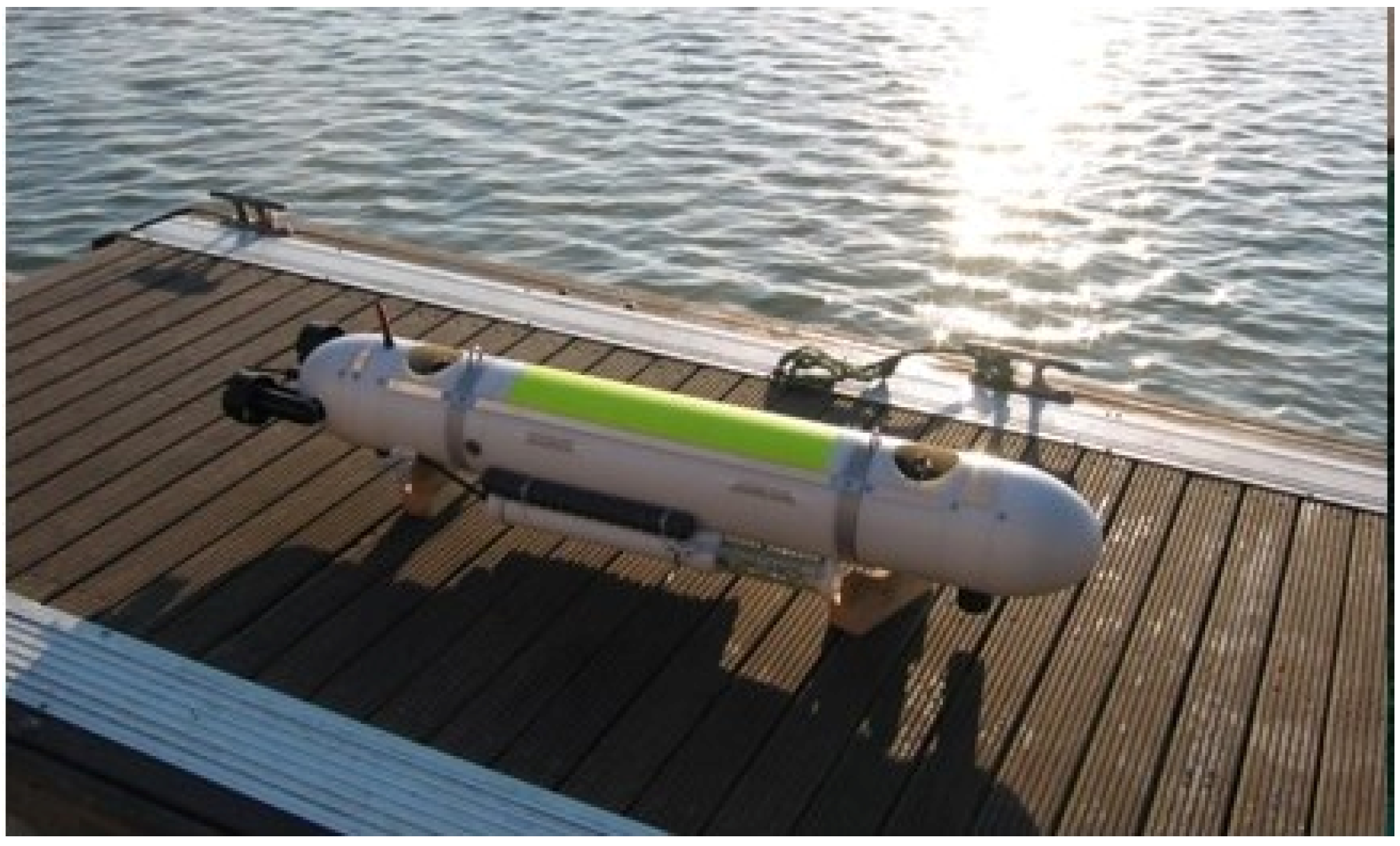
The AUV considered in this work has been developed by the Ocean Systems Group at FEUP/INESC TEC as part of a program for the design of small size AUVs based on modular building blocks. Mechanical parts as well as electronics, software, and control are included in this modularity. The vehicle hulls are assembled as a stack of modular sections with an outer diameter of 200 mm, which have matching edges for easy insertion, removal, or replacement. This means the AUVs length will vary according to the installed modules but not the overall cylindrical profile.
Figure 1 represents MARES, the AUV considered in this work, designed for operation in shallow water areas up to 100 m in depth. The main characteristics of the vehicle are presented in Table 1.
This vehicle was designed to have a natural positive buoyancy around 3.5–7 N, so that in the case of an electrical or software failure it will naturally resurface, allowing for easy retrieval of the equipment. That being said, in order for the vehicle to remain at the same depth, the natural buoyancy has to be countered with the use of vertical thrusters. The power consumed by the thrusters in this situation has been experimentally determined to be kp1 = 19.8 W. When the thrusters are turned off, the AUV begins ascending, achieving a steady-state velocity, ż, of 0.2 m/s. To make the vehicle sink at the same rate, the thruster’s consumption, kp2, was experimentally determined to be 38 W.
3. Mechanical Design of the VBS
Given the modularity of the AUV considered in this work, the VBS system was designed to be easily assembled with the remaining elements of the device. The design of the solution considered the following requirements:
- A total volume change of Dt = ±700 cm3 must be provided to achieve a full buoyancy change, starting from a neutral state, in the face of water density variations with depth and salinity;
- Two VBS modules, one at the stern and one at the bow, must be incorporated in the AUV so as to control pitch and depth independently;
- The VBS’s dry components should fit inside a cylinder with as little length as possible and be under 180 mm in diameter;
- The section of the vehicle containing the VBS should be as close to null buoyancy as possible when in its neutral state;
- Considering the Slocum G2 glider’s ability to deliver 43 cm3/s at no load conditions for the 100 m rated pump [8], a maximum time of tvbs = 15 s was defined for the VBS to perform a full buoyancy change;
- The VBS’s required power should not exceed the power provided by the AUV’s internal power system;
- It should be underlined that the solution was designed with off-the-shelf components, in order to be readily available for assembly.
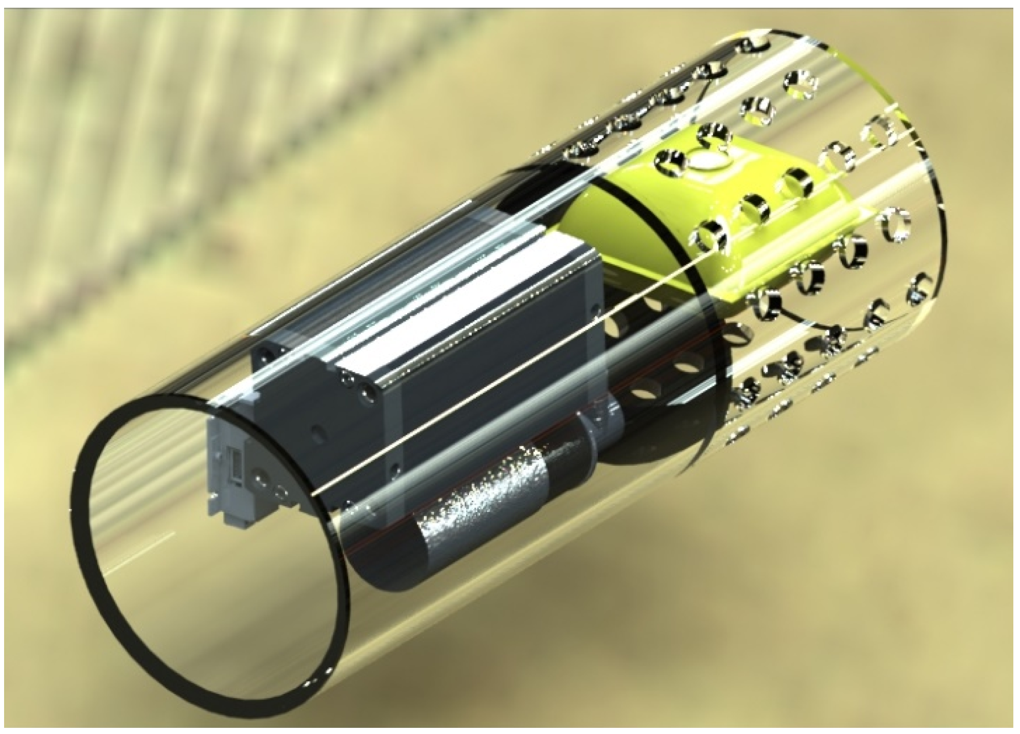
The working principle of the designed solution is simple, namely, to increase the device’s buoyancy, where oil is pumped into an external bladder. To decrease buoyancy, the bladder must be deflated, allowing the oil to return to an internal reservoir.
The internal reservoir chosen was a FESTO double acting pneumatic cylinder (model ADN-80-150). The oil is stored inside one of the cylinder’s chambers, while in the second chamber a spring is inserted, in order to reduce cavitation hazards by pre-charging the oil. It is not simple to measure the volume inside the bladder, so, instead, the amount of oil inside the reservoir is measured, using a position transducer, also provided by FESTO (model SDAT-MHS-M160).
To pump the oil into the bladder, a motor-pump group by Fluidotech (model HA114Z) was selected. This pump can generate up to 10 bar of pressure, meaning the maximum depth achievable by this solution is about 100 m. The flow that must be provided to the bladder should be such that a full buoyancy change is achieved in tvbs = 15 s. As such, the pump must, in any load case, be able to provide Qt = Dt/tvbs. The selected pump can generate more than the target flow at any working point in its pressure range. To control the motor-pump group, a Maxon driver (model ESCON 70/10, 4Q-servocontroller for DC/EC motors, 10/30 A, 10–70 VDC) was chosen.
4. Power Calculation of the Electrohydraulic VBS
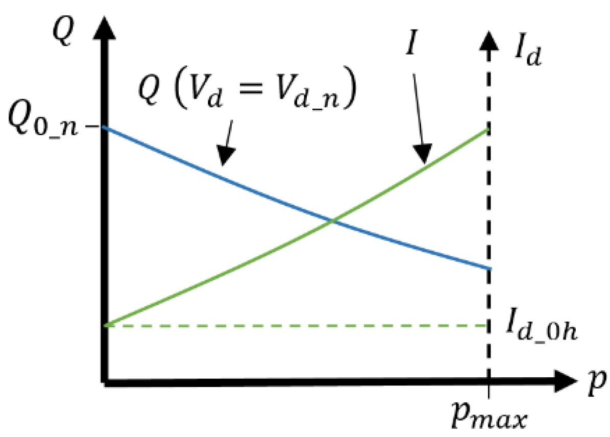
In order to assess the potential energetic savings provided by the usage of an electrohydraulic VBS in AUV’s, in this section, a mathematical model of the power consumption is developed. The traditional way to model this kind of system would be to consider the characteristics of the motor, transmission, and hydraulic pump individually. In this case, however, the manufacturer provides the characteristics of the motor-pump group’s behavior. The flow-pressure and drawn current-pressure curves of the motor-pump are represented in Figure 3 for the nominal supply voltage Vd = Vd_n. In the figure, Q0_n is the nominal no-load flow, pmax is the maximum nominal output pressure and Id_0h the current required to surpass the static friction torque.
The equations describing the characteristic curves are:
where mI/p and mQ/p are the slopes of the current/pressure and flow/pressure curves, respectively. The required variables to determine the target voltage applied to the motor are the target flow, Qt, and the target pressure, pt. It and can be calculated as:
where Vd_0h is the necessary voltage to maintain Id_0h. It can be determined by:
To calculate the target current drawn by the motor, Id_t, F is replaced by Ft in Equation (1):
Assuming that the driver is supplied with a constant voltage, Vt = Vd_t, and that the driver’s losses are proportional to the current drawn by the motor-pump group, the target current at the driver input is given by:
where kd is the driver’s electric loss coefficient. By combining Equations (3)–(6), the required power to actuate the electrohydraulic VBS, Peh, can be calculated:
where
The target pressure can be calculated as pt = ρH20gzt, where ρH20 is the water’s volumetric mass density, g is the Earth’s gravitational acceleration, and zt is the target depth. As stated in Section 3, the target flow can be determined by Qt = Dt/tvbs.
As mentioned in Section 2, the power consumed by the MARES’s vertical thrusters in order to remain at a constant depth is kp1 = 19.8 W, while to descend at a speed of ż = 0.2 m/s, the consumption is kp2 = 38 W. The knowledge of the consumed power by each solution allows for a comparison of the energy spent in a given specific mission profile. This comparison is performed in Section 5.
5. Simulation
Since the main focus of this work was to design a more energetically efficient solution than the existing one, a comparison between the energetic consumption of the designed VBS against and the thruster solution is presented in this section. Table 2 lists the values for the parameters of the mathematical model developed in Section 4. It was considered that the thruster vehicle always has a positive buoyancy of 7 N, while the VBS starts and ends its cycle with neutral buoyancy. It should be noted that, in this analysis, for simplification purposes, motion transients were neglected and a constant descent and ascent velocity (ż = 0.2 m/s) was assumed. It was also assumed that while the VBS is active, the AUV remains in its present state, no matter whether it is moving or stationary. In addition, given the vehicle’s low speed, pressure was considered essentially constant when buoyancy changes occur, no matter whether or not the vehicle is stationary.
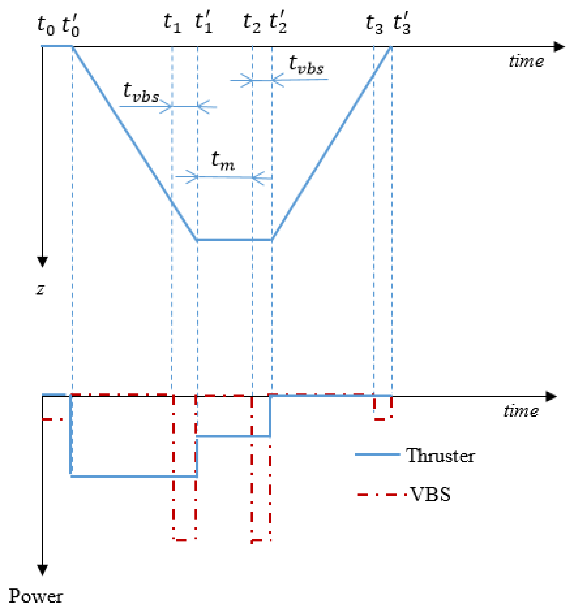
In Figure 4 the assumed mission profile for the energetic comparison is represented. It comprises a dive from the surface to the assigned mission depth zm and resurfacing after after tm + tvbs seconds of data collection.
Given the thruster vehicle’s natural positive buoyancy, this solution consumes energy continuously during the dive [t0′, t1′] and when the vehicle remains at the same depth for data collection [t1′, t2′], but not during the device is resurfacing. As such, and when considering the data presented in Section 2, the thruster-based solution’s energy consumption can be expressed as follows:
The VBS device, on the other hand, consumes energy whenever a buoyancy change is required. Accounting for the mission profile represented in Figure 4, buoyancy changes occur between time intervals [ti, ti′], i = 0, 1, 2, 3. The energy spent by the VBS can then be written as follows:
where tvbs is the time required for a complete a 0 to ±700 cm3 buoyancy change (tvbs = 15 s), and Pvbs0 = Peh(0), and Pvbsm = Peh(zm) for the electrohydraulic converter.
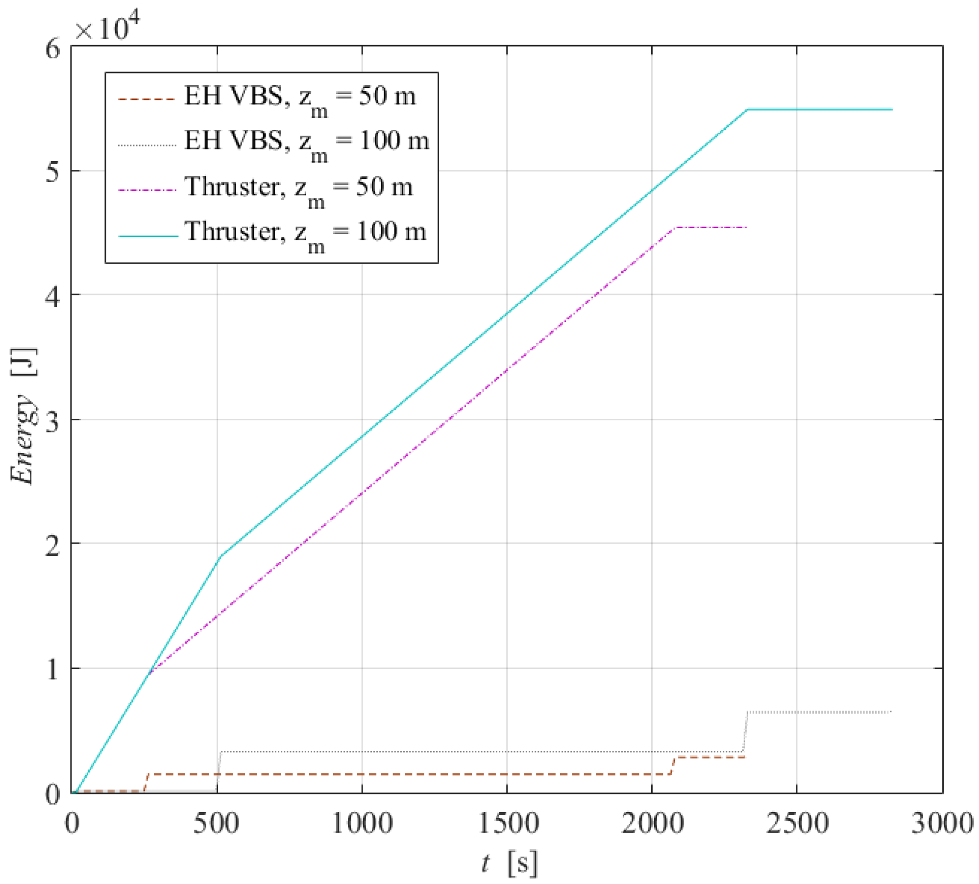
The energy consumption for both solutions in two example missions, one with zm = 50 m and the other with zm = 100 m, when tm = 1800 s, is represented in Figure 5.
Observing Figure 5, it becomes clear that the energy consumed by the electrohydraulic VBS is small when compared to the energy spent by the thruster solution. The latter requires ca. 45,400 J versus 3000 J consumed for a mission where zm = 50 m. In the case of the other mission represented in Figure 5 where zm = 100 m, the thruster consumes about 55,000 J, while the VBS consumes only 6600 J. These values represent energy savings of 93% and 88%, respectively.
6. Conclusions
This work presents a preliminary study regarding the design of an electrohydraulic VBS solution to be used in an existing AUV. The VBS was designed with readily available components for a quick and easy assembly. A mathematical model of the power required to drive the VBS based on the selected components was proposed and used to perform an energetic comparison between the existing and the designed solutions. For the chosen mission profile, the EH VBS leads to energetic savings from 88% to 93%. Future studies will focus on (1) more complex mission profiles, using a combination of both propulsion methods to optimize energetic consumptions, (2) the design of VBS solutions for deep water applications and (3) control tasks, namely, using advanced control techniques like fuzzy [9] or adaptive control [10,11].
Author Contributions
Conceptualization, J.F.C., N.A.C. and F.G.d.A.; methodology, J.F.C., N.A.C. and F.G.d.A.; software, J.B.P., J.F.C.; validation, J.F.C., J.B.P., N.A.C. and F.G.d.A.; writing—original draft preparation, J.F.C.; writing—review and editing, J.F.C., J.B.P., N.A.C. and F.G.d.A.
Funding
This work was financially supported through contract LAETA–UID/SEM/50022/2013 by “Fundação para a Ciência e Tecnologia”, which the authors gratefully acknowledge.
Conflicts of Interest
The authors declare no conflict of interest.
References
- Davis, R.E.; Eriksen, C.C.; Jones, C.P. Autonomous buoyancy-driven underwater gliders. In Technology and Applications of Autonomous Underwater Vehicles; Griffiths, G., Ed.; CRC Press: Boca Raton, FL, USA, 2002; pp. 37–58. [Google Scholar]
- Ranganathan, T.; Thondiyath, A. Design and Analysis of Cascaded Variable Buoyancy Systems for Selective Underwater Deployment. In Proceedings of the 13th International Conference on Informatics in Control, Automation and Robotics 2016, Lisbon, Portugal, 29–31 July 2016. [Google Scholar]
- Masmitjà, I.; González, J.; Gomáriz, S. Buoyancy model for Guanay II AUV. In Proceedings of the OCEANS 2014—TAIPEI, Taipei, Taiwan, 7–10 April 2014. [Google Scholar]
- Asakawa, K.; Hyakudome, T.; Ishihara, Y.; Nakamura, M. Development of an underwater glider for virtual mooring and its buoyancy engine. In Proceedings of the 2015 IEEE Underwater Technology (UT), Chennai, India, 23–25 February 2015; pp. 1–6. [Google Scholar]
- Kobayashi, T.; Watanabe, K.; Ino, T.; Amaike, K.; Tachikawa, H.; Shikama, N.; Mizuno, K. New Buoyancy Engine for Autonomous Vehicles Observing Deeper Oceans. In Proceedings of the Twentieth (2010) International Offshore and Polar Engineering Conference, Beijing, China, 20–25 June 2010; pp. 401–405. [Google Scholar]
- Woithe, H.; Chigirev, I.; Aragon, D.; Iqbal, M.; Shames, Y.; Glenn, S.; Schofield, O.; Seskar, I.; Kremer, U. Slocum Glider Energy Measurement and Simulation Infrastructure. In Proceedings of the Oceans 2010, Sydney, Australia, 24–27 May 2010; pp. 1–8. [Google Scholar]
- Falcão Carneiro, J.; Pinto, J.B.; Cruz, N.A.; Gomes de Almeida, F. Using a variable buoyancy system for energy savings in an AUV. In Proceedings of the 2019 5th Experiment International Conference (exp.at’19), Funchal, Portugal, 12–14 June 2019. [Google Scholar]
- Research, T.W. Slocum G2 Glider Operators Manual; P/N 4343, Rev. B; Teledyne Webb Research: North Falmouth, MA, USA, 2012. [Google Scholar]
- Nuchkrua, T.; Leephakpreeda, T. Fuzzy Self-Tuning PID Control of Hydrogen-Driven Pneumatic Artificial Muscle Actuator. J. Bionic Eng. 2013, 10, 329–340. [Google Scholar] [CrossRef]
- Li, K.; Nuchkrua, T.; Zhao, H.; Yuan, Y.; Boonto, S. Learning-based Adaptive Robust Control of Manipulated Pneumatic Artificial Muscle Driven by H2-Based Metal Hydride. In Proceedings of the 2018 IEEE 14th International Conference on Automation Science and Engineering (CASE), Munich, Germany, 20–24 August 2018; pp. 1284–1289. [Google Scholar]
- Fortuna, L.; Muscato, G. A roll stabilization system for a monohull ship: Modeling, identification, and adaptive control. IEEE Trans. Control Syst. Technol. 1996, 4, 18–28. [Google Scholar] [CrossRef]
Figure 1.
MARES autonomous underwater vehicle (AUV).

Figure 2.
Three-dimensional (3D) render picture of the electrohydraulic solution.

Figure 3.
Electrohydraulic actuator characteristic curves as provided by the manufacturer: Q vs. p and Id vs. p.
Figure 3.
Electrohydraulic actuator characteristic curves as provided by the manufacturer: Q vs. p and Id vs. p.

Figure 4.
Mission and power consumption profiles for the thruster and variable buoyancy system (VBS) solutions.
Figure 4.
Mission and power consumption profiles for the thruster and variable buoyancy system (VBS) solutions.

Figure 5.
Energy spent by the VBS and thruster solutions in a mission where zm = 50 m, zm = 100 m, and tm = 1800 s.
Figure 5.
Energy spent by the VBS and thruster solutions in a mission where zm = 50 m, zm = 100 m, and tm = 1800 s.


Table 1.
MARES characteristics.
| Characteristic | Value |
|---|---|
| First Operation | 2007 |
| Depth Rating | 100 m |
| Energy | 600 Wh, Li-ion |
| Endurance | 10 h or ~50 km |
| Length | 1.7 m |
| Dry Mass | 35 kg |
| Diameter | 20 cm |
| Maximum Width | 30 cm |
| Default Propulsion | Two horizontal, two vertical |
Table 2.
Parameters of the electrohydraulic solution.
| Parameter | Value |
|---|---|
| [V] | 1 |
| [V] | 24 |
| [A] | 0.327 |
| [V] | 0.618 |
| [APa−1] () | 4.624 |
| [m3s−1Pa−1] () | −1.771 |
| [m3s−1] () | 4.856 |
© 2019 by the authors. Licensee MDPI, Basel, Switzerland. This article is an open access article distributed under the terms and conditions of the Creative Commons Attribution (CC BY) license (http://creativecommons.org/licenses/by/4.0/).
Share and Cite
MDPI and ACS Style
Falcão Carneiro, J.; Pinto, J.B.; Cruz, N.A.; Gomes de Almeida, F. Development of an Electrohydraulic Variable Buoyancy System. Information 2019, 10, 396. https://0-doi-org.brum.beds.ac.uk/10.3390/info10120396
AMA Style
Falcão Carneiro J, Pinto JB, Cruz NA, Gomes de Almeida F. Development of an Electrohydraulic Variable Buoyancy System. Information. 2019; 10(12):396. https://0-doi-org.brum.beds.ac.uk/10.3390/info10120396
Chicago/Turabian StyleFalcão Carneiro, João, João Bravo Pinto, Nuno A. Cruz, and Fernando Gomes de Almeida. 2019. "Development of an Electrohydraulic Variable Buoyancy System" Information 10, no. 12: 396. https://0-doi-org.brum.beds.ac.uk/10.3390/info10120396
Note that from the first issue of 2016, this journal uses article numbers instead of page numbers. See further details here.