Article

Constructing a Real-Time Value-Chain Integration Architecture for Mass Individualized Juice Production

1
Faculty of Computing and Information Technology, Tunku Abdul Rahman University College, Kuala Lumpur 53300, Malaysia
2
GMCM Sdn. Bhd., Kuala Lumpur 43300, Malaysia
3
Centre for Postgraduate Studies and Research, Tunku Abdul Rahman University College, Kuala Lumpur 53300, Malaysia
*
Authors to whom correspondence should be addressed.
Submission received: 7 December 2021 / Revised: 14 January 2022 / Accepted: 17 January 2022 / Published: 23 January 2022

Abstract

:
Mass individualized production refers to the mass production of individualized products. It becomes important for delivering a personalized customer experience in the Industrial Revolution 4.0 era. Developing seamless value chain integration between enterprises to achieve mass individualized production is challenging. Based on Reference Architecture Model Industrie 4.0 (RAMI 4.0), this paper aims to address two major challenges, which are asset modeling and integration, and data communication and brokering in a value chain data exchange ecosystem. This paper proposes a communication architecture that enables both vertical and horizontal value-chain integration. A proof-of-concept is built, which involves two stakeholders. The first is the individualized juice online ordering system, named PEC, and the second is a highly automated individualized mixed juice production manufacturing line, named OMIS. Three different tests are conducted in the experiments. The first is to test the creation of assets wrapped in the asset administration shell. The second is to test the connectivity between the Asset Brokering Manager (ABM) Connector and the ABM Portal. Last is to test the connectivity performance between two Asset Administration Systems. As a result, the experiments successfully created the asset instance data accurately, and the data were published in the ABM Portal for subscription by PEC and OMIS. The connectivity tests from OMIS to PEC, and vice versa, were successful, with the time taken of 114 and 121 ms, respectively.

1. Introduction

With the continuous improvement of living standards, customer behavior has shifted towards demanding products that are characterized by individualization, better known as the Customer to Business (C2B) model [1]. It is only in recent years that there has been a demand for a personalized experience when customers make orders of products or services [2]. The shift of consumer behavior towards individualized products significantly affects the existing manufacturing paradigm. The production model of the manufacturing is predicted to move from the traditional mass or batch production manufacturing model to a model that is driven by the customer orders [3]. Modern manufacturing lines shall produce these consumer-driven order items as efficiently as possible. This can be enabled by automation combined with information technology and operation technology, such as Industry Internet of Things (IIoT), artificial intelligence, and cloud computing, to improve accessibility to real-time data. IIoT uses the power of smart sensors, actuators, and real-time data analytics to improve the manufacturing process. The smart sensors, installed at different stations, are interconnected and controlled by computer software to gather huge amounts of data for real-time analysis. This allows the company to monitor, identify, and amend the inefficiencies or problems in any manufacturing processes without any delay. IIoT has been widely used in the field of manufacturing, warehouse, smart utilities, smart city, and so forth, in which the demand for full automation and monitoring are usually high. Hence, effective and efficient management of the distribution of production information and functions throughout the network is a must. A good architecture that allows greater real-time interactions and communication between digital systems across the value stream, for better product lifecycle management and vertical integration, is needed. The architecture must also enable the organization and control of the data exchange across the entire value chain. It is also important to overcome the technical challenges related to data security, high availability, low latency, and scalable resources. A good architecture is needed in enabling cross-company data exchange for both vertical and horizontal value-chain integration.
In April 2013, Plattform Industrie 4.0 was officiated by the German Federal Minister of Economics and Federal Research Minister. Together with its alliance, consisting of companies, academia, associations, and trade unions, they published a reference framework with the German Electrical and Electronic Manufacturers’ Association (ZVEI), called Reference Architectural Model Industrie 4.0 (RAMI 4.0), in 2015 [4,5], followed by DIN SPEC 91345 by the European Standards in 2016 [6], as guidance for Industry 4.0 implementation. Plattform Industrie 4.0 was established to focus on the strategic Industry 4.0 development in order to enable the organization and control of the entire value chain along the product lifecycle. The use of relevant technologies allows the lifecycle to orient itself by fulfilling the increased individual customer requirements.
Based on the RAMI 4.0 guidelines, this paper proposes an architecture that is designed to address two major problems, which are (i) asset modeling and integration and (ii) data communication and brokering. A use case is developed to demonstrate the technical implementation of the Architectural Layers in RAMI 4.0, i.e., Asset, Integration, Communication, Information, Functional and Business Layers. A proof-of-concept (POC) is developed, which simulates the communication between two stakeholders involved in an individualized bottled mixed-juice manufacturing. The first is a retailer who provides an online individualized juice ordering platform, named Personalized E-Commerce (PEC). The second is named One-Piece Manufacturing through Individualization Solution (OMIS), which is a highly automated manufacturing line that produces individualized bottled juices based on customer orders. The POC development involves the integration of the PEC’s sales order asset. Once a customer places an order via the PEC, the asset instance data will be channeled to the OMIS Enterprise Resource Planning (ERP) system for production planning. After the production is completed, the order status will be sent back from the OMIS to the PEC automatically. Detailed information about this POC will be presented in Section 3. The architecture proposed by this paper will be designed and built based on this use case.

2. Literature Review

2.1. Mass Production, Mass Customization, Mass Personalization, and Mass Individualization

Although mass production, mass customization, and mass personalization may be perceived as similar by many people, these three concepts are actually different. Mass production aims to offer affordable products to users, by achieving the lowest cost in the whole process of manufacturing, while turning out the highest volumes possible. In mass customization, customers are provided an opportunity to choose from a limited range of clustered products. Mass personalization, on the other hand, is consumer-oriented. Mass personalization allows the mass production of products with distinct features and value propositions required by individual consumers, enabled by data-driven technologies [7]. In the process of personalization production, customers are involved in the product development life cycle, including design and test. Therefore, the degree of mass personalization is a range between mass production and the unique characteristics required by the customers. A higher degree of mass personalization (DoMP) often requires more resources and effort to achieve [8]. Mass individualized production, in the context of this paper, is a manufacturing technique used in a mass personalization strategy to automate the mass production of individualized products. For example, customers can order juice through an e-commerce portal with the ingredients completely based on their individual preferences, rather than following the standard formula offered by the manufacturers. The personalization offers a fulfilling customer experience, which could increase the value of the business, by offering tailor-made juice direct to the consumers. To enable mass personalization, it is important to develop manufacturing lines that automate the mass production of individualized products with the use of relevant technologies [9,10].

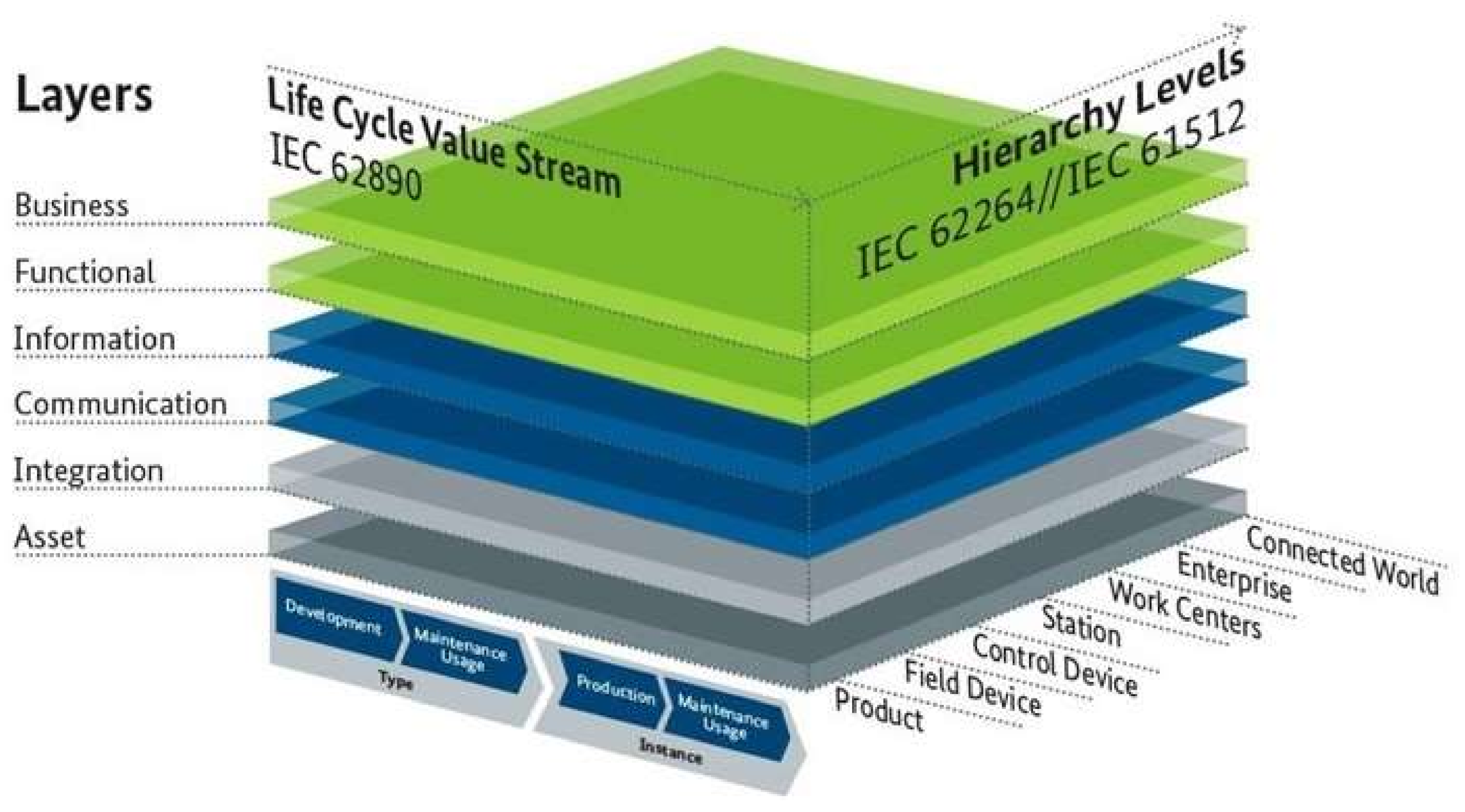
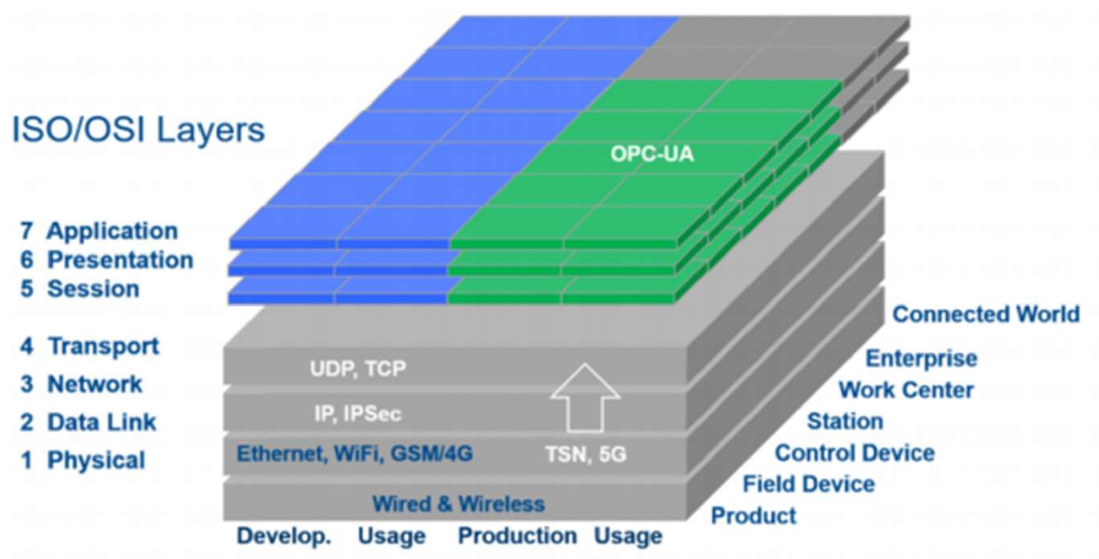
2.2. Reference Architectural Model Industrie 4.0 (RAMI 4.0)

In April 2015, Platform Industrie 4.0 and the German Electrical and Electronic Manufacturers’ Association (ZVEI) published a reference architecture known as Reference Architecture Model Industrie 4.0 (RAMI 4.0), as shown in Figure 1 [4]. Then, in 2016, the European Standards published the DIN SPEC 91345, which describes the detailed specifications of RAMI 4.0 [6]. RAMI 4.0 is a reference framework for digitization, which is represented by a three-axis model for the manufacturing industry to approach the issues of Industry 4.0 in a structured manner [5]. The three-axis model unifies vertical integration, horizontal integration, and the product lifecycle in the value stream. Different business strategies, such as the product life cycle extension strategy, can be derived through value creations along its supply chain [11]. In general, RAMI 4.0 provides guidance to the manufacturing industry through the step-by-step implementation of Industry 4.0.
The first axis is known as Hierarchy Levels, which is based on IEC 62264/IEC 61512, the international standards series for enterprise-control system integration [4] and batch control (https://webstore.iec.ch/publication/5528) (accessed on 6 December 2021). It refers to the manufacturing automation that enables product value recovery by improving process effectiveness, efficiency, and performance using related functionalities, which include workpieces, PLC, SCADA, MES, MOM, and ERP solutions to the Internet of Things and Services. The second axis, which is the Life Cycle Value Stream axis, enables product lifecycle management for both “type” and “instance” products. According to Lee [11], this axis is important to increase the product value by allowing traceability throughout its lifecycle. The benefits include fast market penetration, increased market growth, and prolonged product maturity. It is also very useful for lean manufacturing to reduce the chance of delay of schedule, material waste, and excessive resource consumption in non-value-added processes. However, there is a challenge in implementing Industry 4.0, which is to enable interoperability and autonomy (sovereignty) among the proprietary systems and solutions provided by the large manufacturing automation providers [13].
The last axis, namely the Architecture Layer, caters to business needs by focusing on the idea of digital asset data modeling and sharing. It provides “Models and Standards” in respect to the structure of the implemented Asset Administration Shell, or Industry 4.0 Component [14]. It caters to business needs to ensure interoperability and autonomy. Schweichhart [5] explained how the data could be exchanged, grouped as an asset, and used in the Functional Layer. According to DIN SPEC 91345 [15], the last Business Layer of the Architecture Layers enables mapping and linking between different business models and ensures the integrity of the functions within the value stream [16,17]. The Information Layer describes the data that is used, generated, or modified by the technical functionality. This includes a runtime environment for pre-processing of events, consistent integration of different data, and a formal description of models and rules. The Information Layer receives events and data objects from the Communication Layer in the Architecture Layers and pre-processes them into information objects and data models [18]. These information objects and the data models are then used for functions and services residing in the Functional Layer to enable system interoperability by allowing information exchange regardless of communication means. The Communication Layer describes Industry 4.0-compliant access to the information and functions of the connected assets. In other words, it manages the exchange of data between company, i.e., which data is used, where it is used, and when it is distributed. The Communication Layer that is mapped to the ISO/OSI model is shown in Figure 2, which describes protocols and mechanisms for interoperable information exchange between assets. The Communication Layer enables communication across hierarchy levels and the life cycle of assets (I4.0 components). The communication between different architecture layers is achieved using uniform data models.

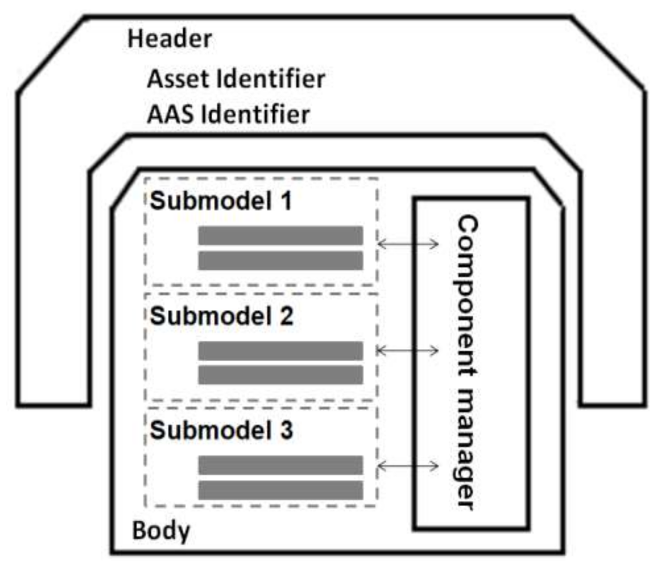
2.3. Data Modeling with Asset and Asset Administration Shell

An asset is defined as anything that creates value for an organization [4]. Asset appears to be the most fundamental layer of the Architecture Layers axis in RAMI 4.0 (see Figure 1); it represents a thing in reality, such as physical components, including machines, documents, and persons, or non-physical objects such as software or business processes, as long as they need to be connected to the cyberspace. The Asset layer forms a part of the connection across the entire Architecture Layers axis to the virtual world, from the Integration Layer up to the Business Layer [19]. Functional software in the Functional Layer of RAMI 4.0 can be developed to make use of the integrated assets data to generate values such as increasing capacity, tracking assets’ availability, and improving production efficiency. A recent publication by Plattform Industrie 4.0 [20] suggested the benefits of implementing an Asset Administration Shell (AAS), such as allowing the complete life cycle of products, devices, machines, and facilities, enabling integrated value chains, and being the digital basis for autonomous systems and artificial intelligence. Asset-oriented applications development in recent years, for example [21,22,23,24,25,26,27,28], has shed light on the implementation of data-driven smart manufacturing.
The Architecture Layers axis is important in enabling seamless information sharing throughout the entire manufacturing supply chain. One of the basic Industry 4.0 components that enables a common communication structure between parties is to surround every asset with an AAS. The I4.0 component, also known as a digital twin, i.e., an asset wrapped in the AAS, allows any business to organize these assets for specific purposes [29]. IEC TS 62832-1:2020 [30] provided a framework called the Digital Factory Library, in which digital assets are created to store the information as classes in the library. Brokering out this information allows various organizations to be able to search and connect with each other to perform business together. These business transactions are what make up a supply chain. Without this, it is more challenging for organizations to easily communicate and transfer information across.
The AAS is made of a series of submodels [31]. It is composed of a body and a header. The header contains identifying details regarding the AAS and the represented assets in reality. Figure 3 shows a general structure of AAS. The body contains a number of sub-models that specify the characterization of the AAS, such as security, its process capabilities, and connection. Each submodel contains a structured quantity of properties that can connect to data and functions that may reside in other locations and be in various complementary formats.

2.4. Industrial Data Space Reference Architecture Model (IDS-RAM)

The Industrial Data Space (IDS) is a virtual construct for secure data sharing based on standardized communication interfaces and common governance models. It aims to create an ecosystem that facilitates a secure environment for the exchanging of data and to ease the linkage of data in business ecosystems [32]. The IDS was created and launched in late 2014 in Germany and was funded by the German Federal Ministry of Education and Research (BMBF). IDS was established as a foundation for Industry 4.0 by ensuring security, such as certificates, for data exchange between organizations without the loss of data sovereignty. To help the initiative of the IDS, the International Data Spaces Association (IDSA) was formed to promote the continuous development and sustainability of the IDS [33]. It is an open and non-profit organization. The IDSA has an open community for members of the association to chat and discuss any matters related to the IDS. There are also various documents and guides to help new users to adopt the IDS. In 2017, Industrial Data Space Reference Architecture Model (IDS-RAM) was published to enable a reliable data exchange ecosystem between companies, with common rules to be implemented in the Communication Layer of RAMI 4.0. Data sovereignty is, thus, a central aspect of the IDS. Besides specifying the rules to ensure data sovereignty within data ecosystems, the IDS-RAM, published by IDSA [34], consists of five layers, which are the business layer, the functional layer, the process layer, the information layer, and the system layer. The standards materialized in the IDS-RAM and DIN SPEC 27070 [35] define methods for secure data exchange between the various Industrial Data Space connectors. Figure 4 shows that each connector is able to communicate with every other connector or component in the ecosystem of the Industrial Data Space to allow any organization to communicate with the outside world in real-time.
The IDS consists of three core components that give control of the data flow. The first is endless connectivity, where a component behaves as a standard for data flows to all data endpoints. The second is to establish trust between different security domains. To help generate maximum trust to the end-user, various security functions have to be comprehensive and complex. Last is the governance for the data economy, which introduces data usage control and enforcement. There are four basic roles of the IDS, with each role performing a specific function and contributing to the ecosystem as described below.
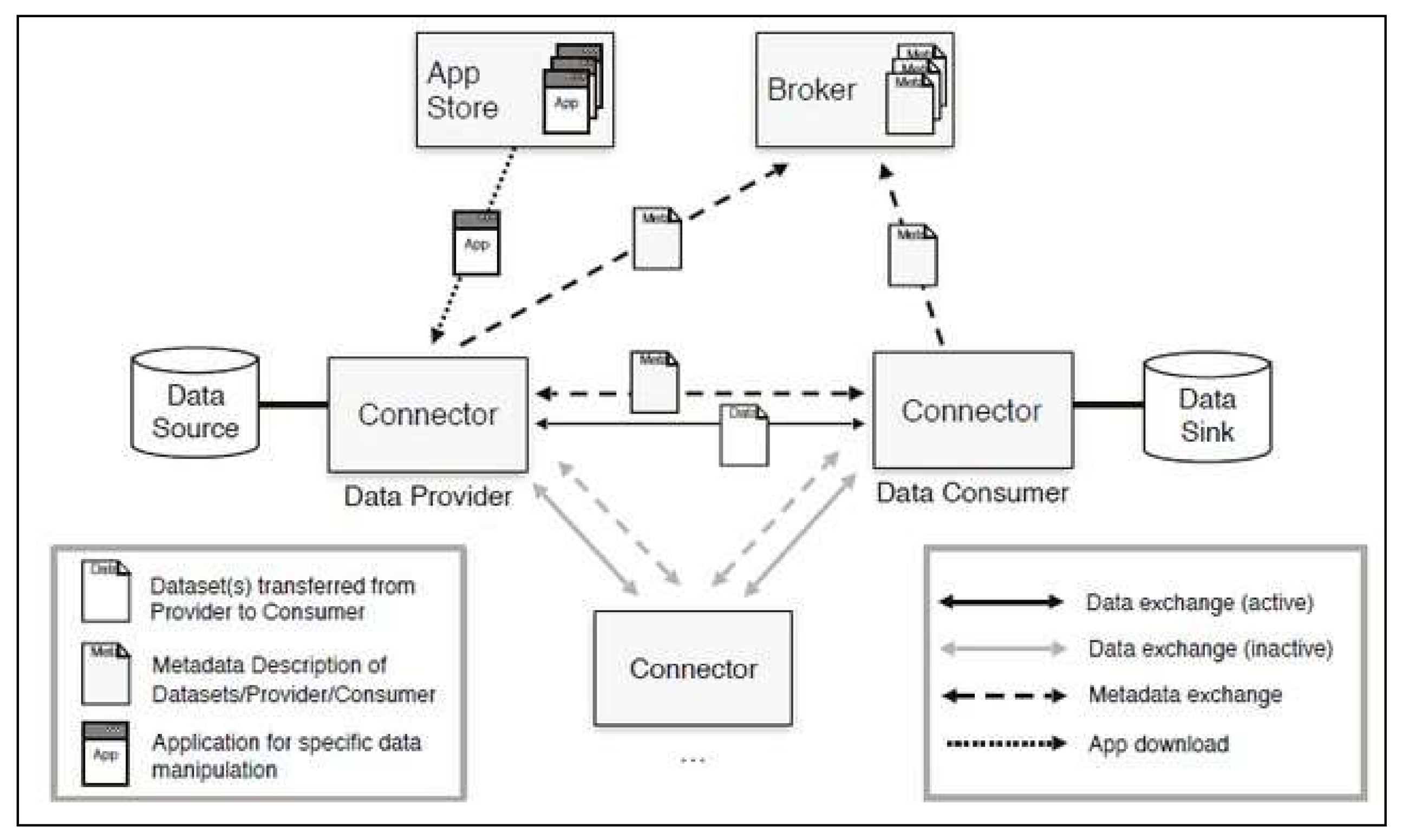
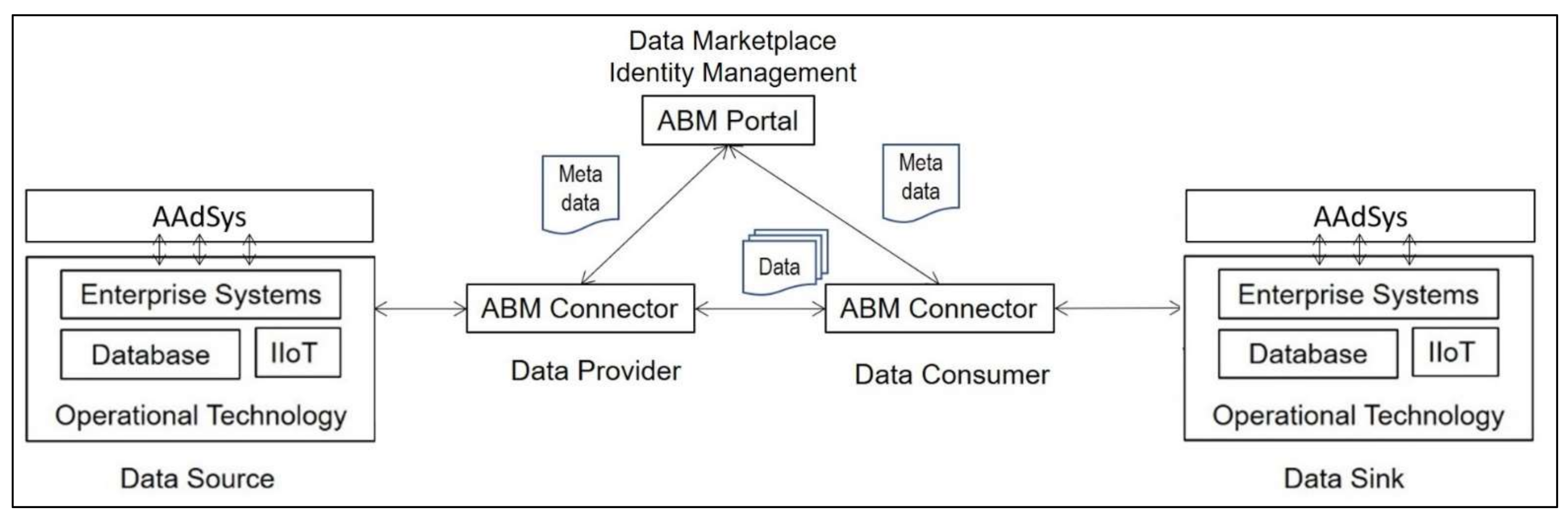
  • Data Provider/Owner. Data Provider is defined as a person who holds rights to a data that brings value to the organization. The role of which it performs is to offer its data to other participants of the Industrial Data Space.
  • Data Consumer/User. They use the data provided by the Data Provider. The Data Consumer can request data from the Data Provider to use that data for providing services or internal purposes.
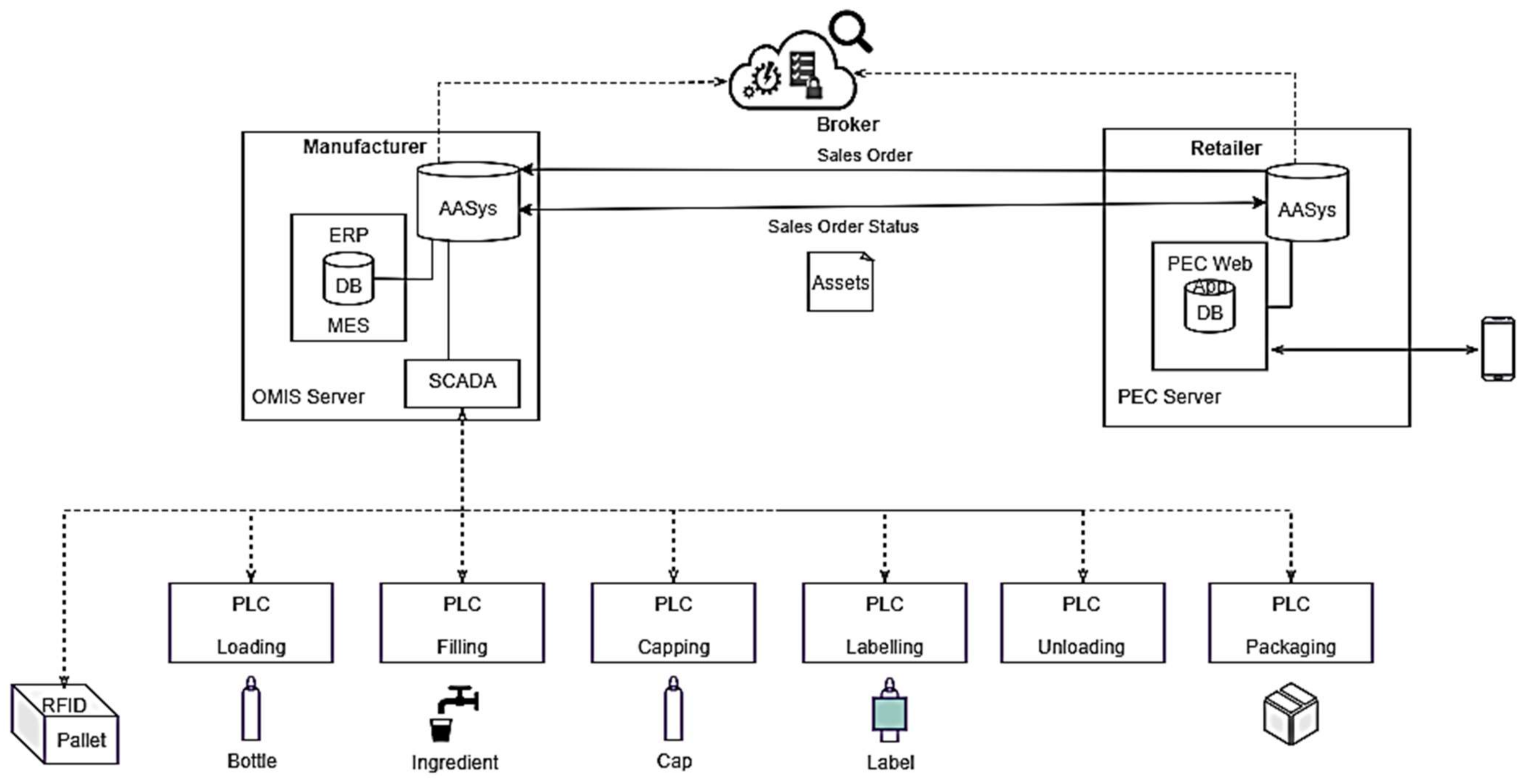
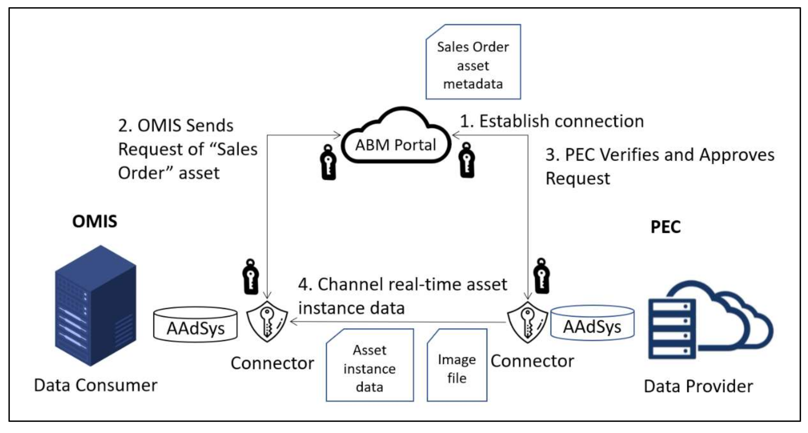
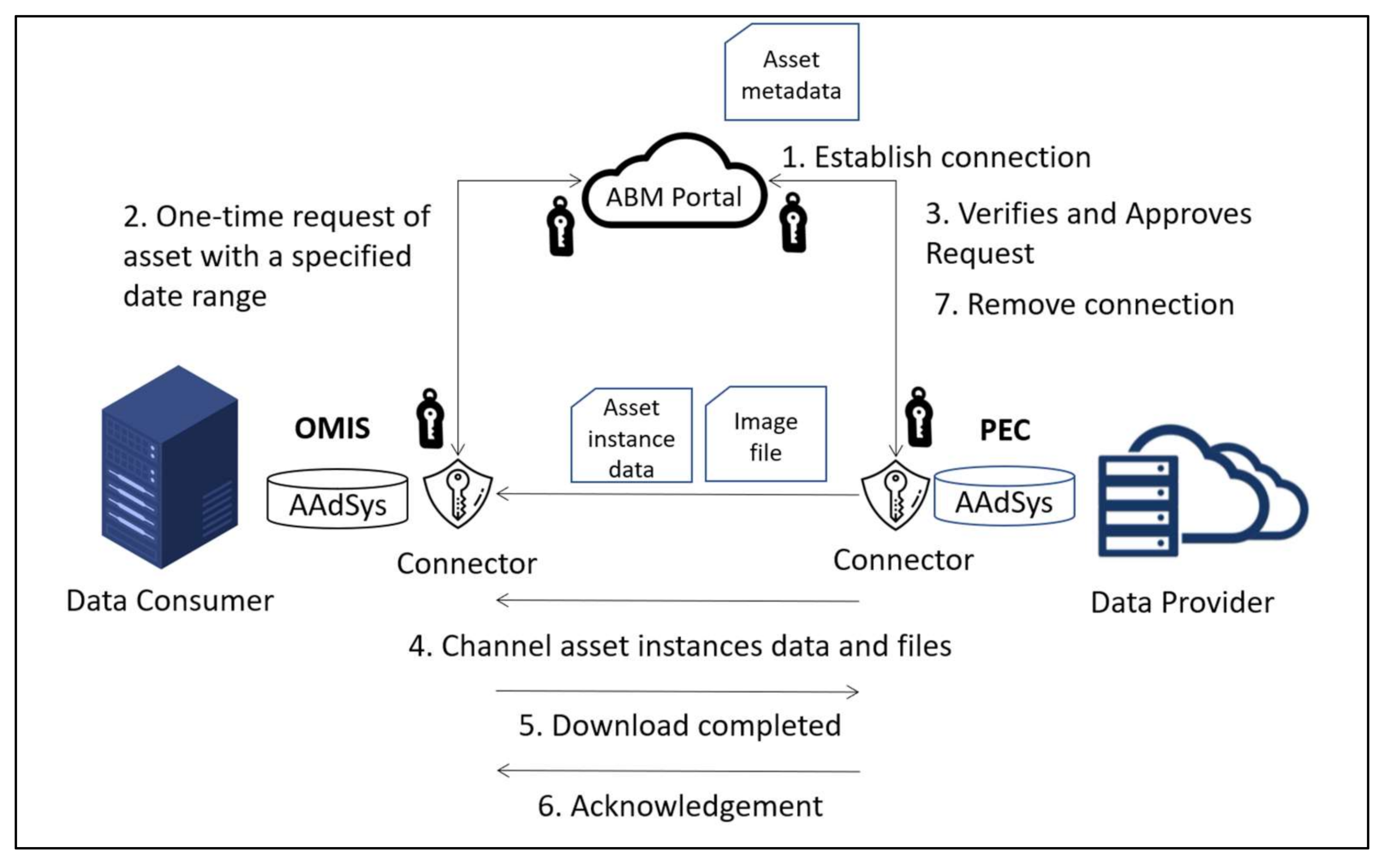
  • Broker. Broker is an index-service running in conjunction with an IDS Connector that helps facilitate data exchange between both the Data Provider and the Data Consumer. In IDS, the Broker provides Data Providers with functions to publish their asset metadata, provides Data Consumers with a function to search the data of the Data Providers, and provides functions to both parties to make an agreement for the provision and use of their data. The Broker also acts as a supervisor who will manage the data exchange between both parties by ensuring that all data are transferred to the respective party in a secure manner while maintaining data sovereignty. Data sovereignty refers to the compliance of a set of rules, or terms and conditions, that are created by the Data Provider for the Data Consumer or by a governance body on the data exchange by the three roles. This provides protection to the Data Provider; in the event that any user uses the data without permission, he can take legal action on the unauthorized user. The interaction between both the Data Provider and the Data Consumer and the Broker can be seen in Figure 4.
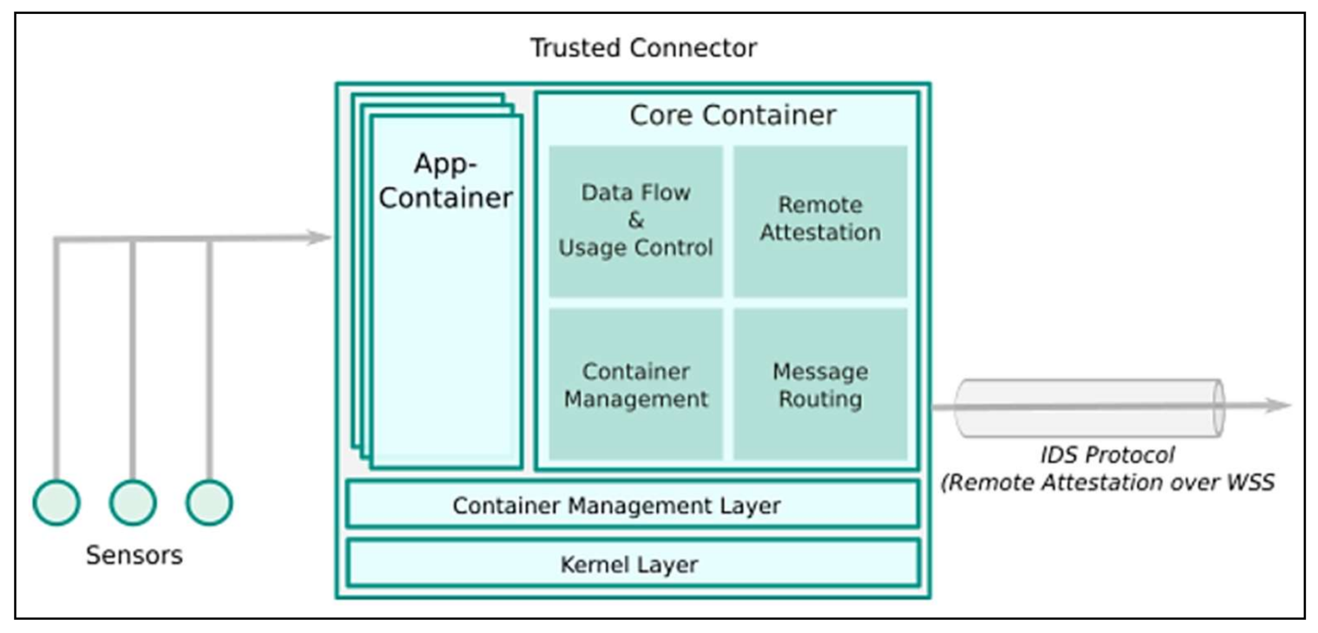
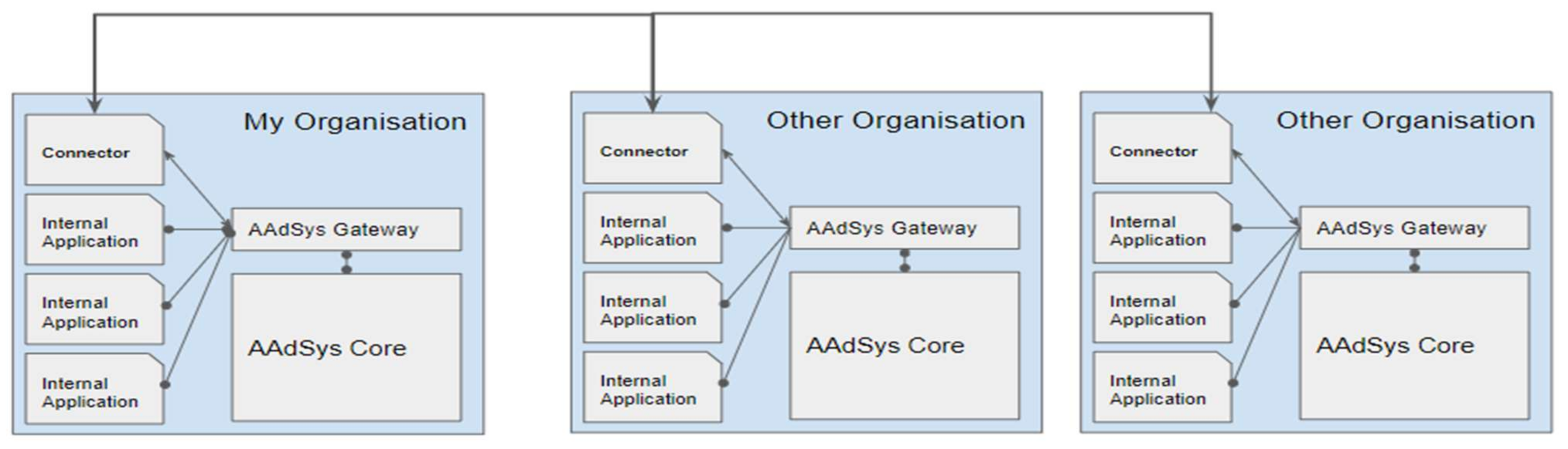
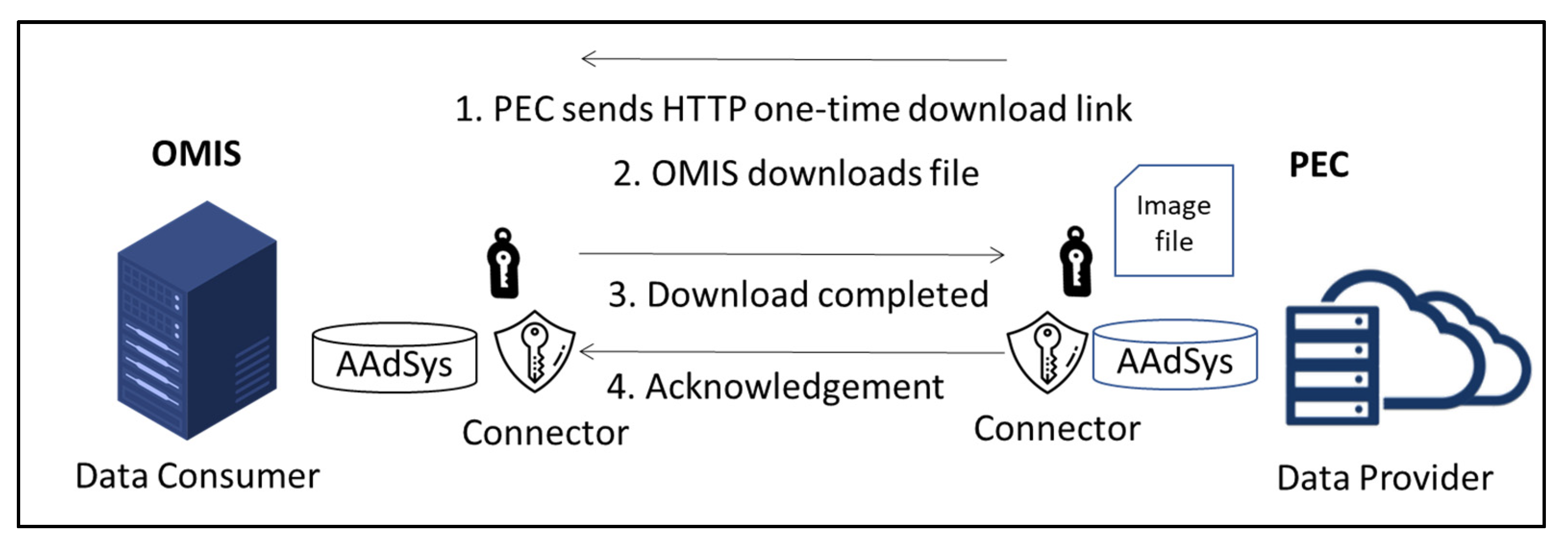
  • Trusted Connector. This component is a service in the IDS that allows data to be kept in a container, such as asset data and sensor data, to be processed and transferred to the other party (see Figure 5). The trusted Connector has to work together with the Broker to enable communication between a Data Provider and a Data Consumer.

2.5. Service-Oriented Architecture (SOA) and Microservices

The focus in Service-Oriented Architecture (SOA) is believed to have transformed traditional software systems into reusable, business-relevant services. Web service technologies, such as Extensible Markup Language (XML), Web Services Description Language (WSDL), Simple Object Access Protocol (SOAP), and UDDI (Universal Description, Discovery, and Integration) have commonly been used for the implementation of SOA in the past [36]. Recently, microservices architecture [37] appears as another promising variant of service-oriented architecture (SOA) technology [38], which is built from a collection of services. Each individual service contains very minimal functions and runs on its own process autonomously. The collection of the microservices is loosely coupled, which overcomes the limitations of the monolithic architecture that composes all modules into a single application. The advantages of microservices are to provide the flexibility to modify and upgrade the services without interrupting other modules and to achieve autonomy, isolation, and resilience with the help of external services such as load balancers. A recent study by Santana et al. [39] showed that microservices architecture started being used in IoT applications to improve the performances of large-scale systems. However, microservices architecture can be complex due to modularity and decentralization. Reactive microservices architecture is a specific type of microservices architecture. The reactive property enables a service to be elastic, resilient, and responsive. Therefore, it is considered useful to enable uninterrupted quality service and real-time streaming and secure usage control of data with high volume, high velocity, and high availability. The benefits of the reactive system are important for the development of data exchange ecosystems and timely distributed operations monitoring in Industry 4.0. Since microservices (or SOA) are highly flexible and dynamic but require more complex system architecture, there is a need for service orchestration to ensure the interconnectivity of the services and functions are performed as well as the monolith application. Service orchestration is the arrangement, configuration, and management of the system to ensure the system operates within its ecosystem with the expected behavior. Some modern orchestration tools, such as Kubernetes, Chef, and Ansible, could help to manage those complex designs.

2.6. Brokering System

In Industry 4.0, data are the most important and crucial pieces of information that can bring value to a company when managing its supply chain. Information Brokering System (IB) is a system that collects data about companies and retrieves information for clients. Brokering out information allows various organizations to be able to search and connect with each other to perform business transactions online. Without IB, it is more challenging for organizations to communicate and transfer information across to each other. Historically, IB has proposed to use third-party providers to control and maintain their data, but it is often being questioned whether the data stored on the third-party platform can be trusted; the communication is prone to interference, or the servers are easily hacked. Li et al. [40,41] suggested protocols and solutions to prevent attacks on the system as well as enable encryption for both parties receiving the information. Allowing the sharing of data, businesses are able to provide better service overall by being more efficient; patients can benefit from this too [42]. Xu et al. [43] proposed a framework focusing primarily on preserving privacy when performing the exchange of data in healthcare. Furthermore, this framework complies with laws and regulations, such as the Health Insurance Portability and Accountability Act (HIPPA), to protect the privacy of the patient, which is bound by strict guidelines [44]. The Object Management Group, Inc. (OMG, Milford, MA, USA) created the Information Exchange Framework (IEF) to develop specifications of data-centric information sharing and safeguarding services while being policy-driven. This enables information to be shared in real-time in a vast variety of scenarios [45]. OMG is a non-profit, international, and open membership technology standards consortium group that produces and maintains industry specifications for interoperable, portable, and reusable enterprise applications in heterogeneous and distributed environments [46].

3. Project Background

This section describes the design of the data exchange ecosystem that enables the mass individualized production of bottled mixed juice. A proof-of-concept (POC) is developed to demonstrate the architectural design and functions that enable vertical and horizontal value-chain integration, as shown in Figure 6. In this POC, PEC represents the e-retailer who provides an online ordering system to the end customers, and OMIS represents the manufacturer who produces the individualized bottled juice. They represent both data provider and data consumer in the data exchange ecosystem. To enable secured and trusted data exchange, OMIS is required to navigate through the ABM Portal and subscribe to the PEC’s assets. The value chain connectivity architecture for the asset data channeling is shown in Figure 7. To ensure the sovereignty of asset data, the data access control is managed by individual enterprises, such as to control who can access the information, when to enable the data channeling, and to set the data availability duration. The access control information is added to the information object and data model using JSON, managed in the Information Layer. The Information layer is also responsible for maintaining the connectivity between the shop floor components and establishing secure communication with other enterprises in the value chain. A use case to simulate the value chain connectivity between OMIS and PEC is developed to demonstrate the communication and integration of assets (or components) from the Asset Layer to the Information Layer.
The functions of each entity are explained below.

3.1. Personalised E-Commerce (PEC)

PEC stands for Personalized E-Commerce. It is a mobile web application that accepts and manages orders from online customers to purchase individualized mixed-juice products, as shown in Figure 8. PEC allows customers to customize their juice order, tailored to their individual needs. The customer can mix different ingredients of their choice, which include bottle size, ingredient contents and mixing ratio, label image, and custom text to be stated on the label. In this use case, PEC represents the retailer who manages the transaction and the automated generation of customers’ sales orders. Therefore, the asset known as “Sales Order” will be created automatically when any customer places an order, to be sent to OMIS for made-to-order and on-demand manufacturing via AAdSys.

3.2. One-Piece Manufacturing through Individualization Solution (OMIS)

OMIS, an acronym of One-Piece Manufacturing through Individualization Solution, is a manufacturing line for individualized mixed-juice production. The overview of the OMIS vertical and horizontal integration architecture is shown in Figure 9. OMIS represents the manufacturer that manufactures individualized products based on the “Sales Orders” asset received from PEC. The Enterprise Resource Planning software (ERP) manages the sales order received from PEC, the production schedule is managed by the Manufacturing Execution System (MES), and the manufacturing automation is managed by SCADA. Each station is controlled by a PLC. As shown in Figure 10, the OMIS manufacturing process involves six stations, i.e., loading, mixing, filling, capping, printing, and packaging. The product, i.e., the bottled juice, is traced using RFID, and the field devices (sensors) that produce real-time production data are recorded in the control device (PLC) at each station. At the end of the production, the data regarding the entire work center, i.e., the individualized mixed-juice manufacturing line that comprises six stations, are channeled back to MES via SCADA. The “Sales Order Status” asset is sent to the ERP and channeled back to PEC via AAdSys. This sales order status is important for PEC to update its customers that their orders are completed and ready for collection or shipment. Figure 11 shows the physical view of the actual OMIS manufacturing line.

3.3. Asset Administration System (AAdSys)

AAdSys, an acronym of Asset Administration System, is designed based on the Asset Administration Shell. It is developed as an interface for data residing in existing applications, to be integrated together. One of its core functions is to manage data communication and channel data internally or externally between systems or enterprises. AAdSys plays the main role in establishing value chain connectivity and system integration between different systems. The POC being developed in this use case is to enable asset data channeling between PEC and OMIS, as well as between ERP and the shop floor systems. The asset data channeling begins with the creation of sales orders through the PEC application. AAdSys then manages the “Sales Order” asset data in the PEC server, which is wrapped in the Asset Administration Shell. The data objects are then channeled to OMIS via HTTP protocol. On the other side, the data objects are received by the AAdSys in the OMIS server. The data objects are then integrated into relevant systems, such as ERP and functions needed by the OMIS. The ERP then processes the sales order information, and the necessary production data are sent to the MES for production scheduling.
The logical architecture of the Asset Administration System (AAdSys) that manages all asset data is shown in Figure 12. AAdSys consists of several main functions, i.e., to generate assets by wrapping data into the Asset Administration Shell, to allow the query of instance data; to store instance data, to store and retrieve files or media associated with the assets, and the authentication of asset data access control. It also supports data connectivity over web transfer protocol through Web API to ensure the interoperability between the AAdSys and other components, functions, and services, such as ERP, MES, SCADA, and PEC applications.
AAdSys consists of a Gateway, a Connector, and a Core. The Gateway establishes the RESTFUL API interface that allows any internal function or service to communicate with AAdSys. The Connector manages all external communications with another AAdSys, which stays in other enterprises in the value chain. The Connector is also responsible for publishing the asset metadata to the Broker [47] and ensuring secure connections for asset data channeling. The Core manages message queues, raising events, and the transmission of real-time data. It ensures all instance data are sent correctly with a two-tier confirmation. It also implements duplication detection, checks time-to-live (TTL) for unsent data, and carries out various authentication and validation functions. The Core also handles all AAdSys core operations, such as wrapping asset data with the Asset Administration Shell, storing instance data, files, and digital media associated with the assets, and allowing the querying and retrieval of asset data within the system.
The format to create the Asset Administration Shell for the physical asset is shown in Figure 3. The Asset Administration Shell consists of metadata as a header and sub-models, i.e., ingredients, nutrition facts, sales orders, and seasonal pricing. The metadata contains general information about the asset. The metadata does not contain any raw values of the asset. It is used by the ABM Portal for indexing purposes. Once these metadata are indexed, it allows other organizations to view the assets that they wish to subscribe to on the ABM Portal.

3.4. Asset Brokering Manager (ABM)

ABM, the acronym of Asset Brokering System, allows data providers and data consumers to publish their assets, to view various organizations, and to subscribe to the assets of their choice. The ABM consists of two systems: an online portal named the ABM Portal, and the ABM Connector, a trusted connector residing in the AAdSys. The overview architecture of the asset data channeling between enterprises is shown in Figure 13. One of the main advantages of the ABM is to ensure data security, effective asset management, and to prevent unauthorized third parties from making illegal data communication. All systems, services, or applications that are connected to the ABM are trusted first parties. The ABM Portal also acts as a data marketplace, which allows the registered organizations to publish their assets through AAdSys. The organizations are able to select any asset data that they want to make available to public view. This allows other registered organizations to browse for the publicly accessible assets that they might be interested in subscribing to. When an organization find any assets that they wish to subscribe to, they can send a request to the data provider and specify a date-range valid for data exchange. The data provider then needs to approve or reject the request based on their consideration. Should the asset get approved, the ABM Connectors will automatically establish a connection between the data provider and the data consumer. The ABM Portal also provides various services that the ABM Connectors can use to verify all transactions for communication.
The ABM Connector is an independent service that is connected to the AAdSys and ABM Portal. It plays an important role in the communication between a data provider and a data consumer. Any approved request of subscription is created in the ABM Portal; the related assets will be channeled over to the data consumer AAdSys using a secure web socket channel, according to the specified date range. All transaction updates done at the ABM Portal will be monitored and verified by the ABM Connector automatically using the ABM Portal services built with RESFUL APIs. To enhance security, both parties are to send a secret key that is generated by ABM Connector when making the API call, and the ABM Portal is to verify the authenticity of the incoming request. There are two types of data channeling modes that can be chosen upon the request of asset subscription, i.e., historical and real-time, in which both are subject to the date range being specified. For instance, the data consumer can request 1-year historical data starting from 1 January or real-time data channeling for the coming six months. Every time the assets data are channeled over, the ABM Connector will send a notification to the ABM Portal to update the data consumer about job completion.
To demonstrate this concept in the POC of this use case, before any data can be channeled between OMIS and PEC, the OMIS owner must subscribe to the desired assets published by PEC, i.e., the “Sales Order” asset, with a specified date range. Upon request, the administrator of PEC has to decide whether to approve or reject the subscription. Once approved, the custom module in the AAdSys of OMIS will automatically connect to the ABM Portal to validate the request and to check for the details of the assets needed to be channeled from PEC, according to the specified date range. In order to receive the notification of the production status information from OMIS, PEC must also subscribe to the “Sales Order Status” asset that belongs to OMIS. The same approval process involved in the ABM Portal is applicable to the OMIS owner as well. For any approved request established, the requested data that are entered to the AAdSys of the Data Provider will be channeled to the AAdSys of the Data Consumer. For instance, when there is a new order created on the PEC’s application, the “Sales Order” asset data will be sent to OMIS AAdSys. The “Sales Order” asset is the sales order data wrapped in the Asset Administration Shell, a format that is accepted by AAdSys. The OMIS Connector will then receive the “Sales Order” asset data through the RESTFUL protocol. Similarly, once the OMIS manufacturing line has completed a job, the “Sales Order Status” asset will be created and channeled to the PEC, received by the PEC Connector, and then stored in the PEC AAdSys. The PEC AAdSys will then update the sales order status to the PEC Online Ordering System database.

4. Experiment Setup

Figure 14 shows the architecture design of the AAdSys framework. A POC is built to test the horizontal and vertical integration in the value chain that involves PEC and OMIS. Three test cases are developed. The first is to test the creation of assets wrapped in the Asset Administration Shell created with the JSON object. The second is to test the connectivity between the ABM Connector residing in the AAdSys and the ABM Portal. The last is to test the connectivity performance between the two Asset Administration Systems (AAdSys). The details of the three test cases are described below.

4.1. Testing PEC AAdSys in Creating Assets and Instances

To test the data channeling between the PEC and OMIS, the “Sales Order” asset is created. The PEC application must generate instance data of the “Sales Order” asset whenever a customer places an order and then wrap the data into the AAS format, as shown in Figure 15. A sample AAS format is shown in Figure 16. The AAS is in the JSON format, i.e., the key-value pair format. It is used as a data model for storing instance data. Hence, the asset instance ID must be unique to every transaction. For the “Sales Order” asset, the order identifier (ID) is used as the instance key while the sales order data is the value, which data objects are generated. The key-value pairs are used to manage the asset instances, allowing the instance data to be queried and retrieved based on the key. This data model establishes common semantics and enables data objects to be easily channeled between the AAdSys of PEC and the AAdSys of OMIS for seamless data communication and integration.
The class diagram that represents the “Sales Order” asset model is shown in Figure 17. It contains metadata and instance data stored in arrays. The “Sales Order” asset is maintained in the AAdSys, to be shared with OMIS. All the asset instance data are kept in the PEC server to ensure data sovereignty. The data will only be shared with other enterprises, such as OMIS, with authorization from the PEC administrator and vice versa.

4.2. Connectivity Test between Asset Brokering Manager (ABM) Connector and ABM Portal

The purpose of this experiment is to demonstrate a working real-life use case featuring the value chain integration across multiple parties. The test case is to establish a connection between the ABM Portal and the ABM Connector, and to perform two-way communication. It aims to enable communication between multiple ABM Connectors, and all data are being processed properly through the AAdSys. Figure 18 shows the infrastructure diagram of the connectivity setup between the PEC and OMIS. An AAdSys is set up in a cloud server for PEC, and one is deployed in an on-premise virtual server for OMIS. The ABM Connector of OMIS is continuously waiting for any new asset instance data sent by the AAdSys in PEC. The AAdSys first receives a sales order from the customer through the PEC online ordering system. Then, the AAdSys transforms the sales order data into a “Sales Order” asset instance according to the “Sales Order” asset model, as shown in Figure 17. Lastly, it stores the instance data of the “Sales Order” asset into the AAdSys database. The asset data object, represented in key-value pairs or the JSON format, is then ready to be channeled. The ABM Connector will then initiate and encrypt the data channeling to OMIS. After receiving the new instance data of the “Sales Order” asset by the ABM Connector, it will then validate the data objects, decrypt the data, and unpack them back into the original model. The ABM Connector then stores the asset data into the AAdSys database. The Gateway will then publish this data internally to other functions, such as ERP, which require the “Sales Order” asset data to perform production planning, such as determining the raw materials needed for bottling, ingredients mixing, and labeling. At the end of the production process, a “Sales Order Status” asset instance is generated by the OMIS AAdSys, to be sent back to the PEC.
The ABM Portal is set up to enable applications, systems, and services to communicate and exchange asset data with each other. Organizations are allowed to upload and publish their metadata to the ABM Portal via AAdSys. An example of ABM Portal user interface is shown in Figure 19. The ABM Connector is designed to run as a web service, using SignalR to transmit asynchronous real-time data with its own dedicated port. For testing, the ABM Connectors were running Windows IIS. As shown in Figure 20, upon starting the service, the ABM Connector will immediately interface with the ABM Portal using an API key as a token to get all verified permissions. Upon receiving the permissions, the OMIS Connector will then take the information received to start connecting to the PEC Connector. When the data consumer begins the request, the data provider will then take this request and verify it with the ABM Portal once more to ensure the incoming request is valid and approved. Once verified, PEC, as the data provider, will allow the data consumer, OMIS, to receive the real-time “Sales Order” asset instances so that whenever there is a new instance added to the PEC database, the data consumer will receive the asset data in real-time.
As part of the AAdSys framework, files, such as label images, are a type of media that can be transmitted to data consumers. However, due to the limitation of SignalR and the protocol for the transmission of data, there is a message limit of 32 kb. To overcome this issue for larger media file sizes, whenever the ABM Connector of PEC detects a new file has been added, it will generate an HTTP one-time download link. This link will then be sent via SignalR, and the receiving ABM Connector of OMIS can then use this link and perform an HTTP download. All processes are done seamlessly and require no input from the user. Upon downloading and saving the file, the data consumer sends a notification that it has been downloaded, and the data provider will acknowledge that the file has been sent. The file transfer activities are shown in Figure 21.
For historical data, the received data will be channelled based on the date-time requested by the data consumer at the ABM Portal, as shown in Figure 22. Similar to how the ABM Connector establishes a real-time connection, the ABM Connector will attempt a one-time connection to the data provider to request the instances of data. The ABM Connector will once again communicate with the ABM Portal to verify the incoming request. Once verified, the data provider’s ABM Connector will communicate with the AAdSys’s gateway to gather all data within the date range requested. This, in turn, will send the instance data and all related files (if any) to the ABM Connector that has requested it. Once all data has been sent out, the data owners’ ABM Connector will automatically send a notification to the ABM Portal to indicate that data has been sent out. At the same time, the data consumer’s ABM Connector will also automatically notify the ABM Portal that they have successfully received the requested data. Once the ABM Portal receives notifications from both parties, the asset will no longer be allowed to be shared and will be marked as a completed transaction.
The process of sharing of “Sales Order Status” asset by OMIS to PEC to update the status of production is the same as above, except that, this time, the data consumer is PEC and the data provider is OMIS.

4.3. Connectivity Performance Test between Asset Administration Systems of PEC and OMIS

This test case is to evaluate the performance of the connectivity between the two AAdSys. Each time, 100 kb asset instance data are to be uploaded and downloaded through AAdSys. A total of 1000 sequential tests are to be conducted to calculate the average data channeling time. The data are randomized on each creation to simulate wide varieties in a real-world scenario. Data are also prevented from being cached by the server, which may affect the results.

5. Results

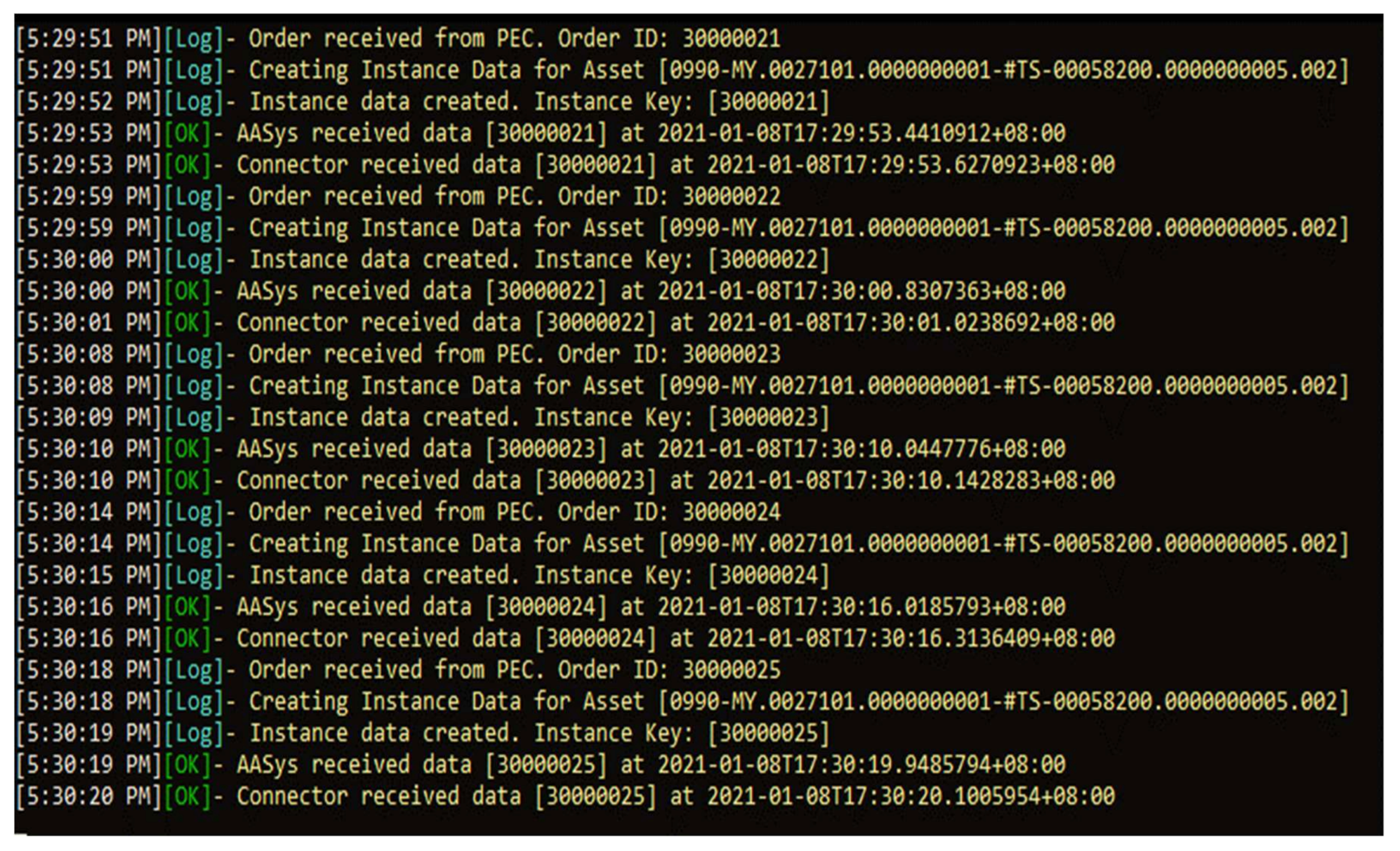
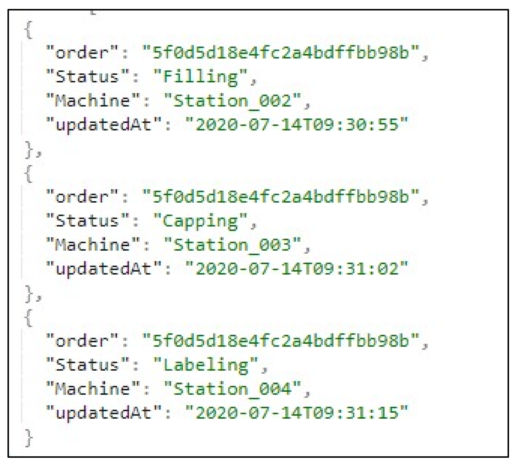
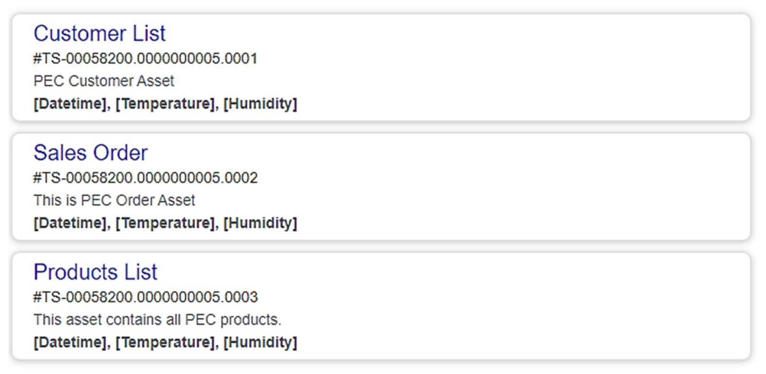
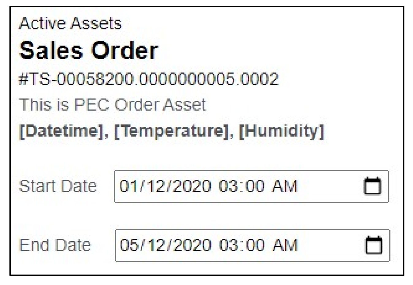
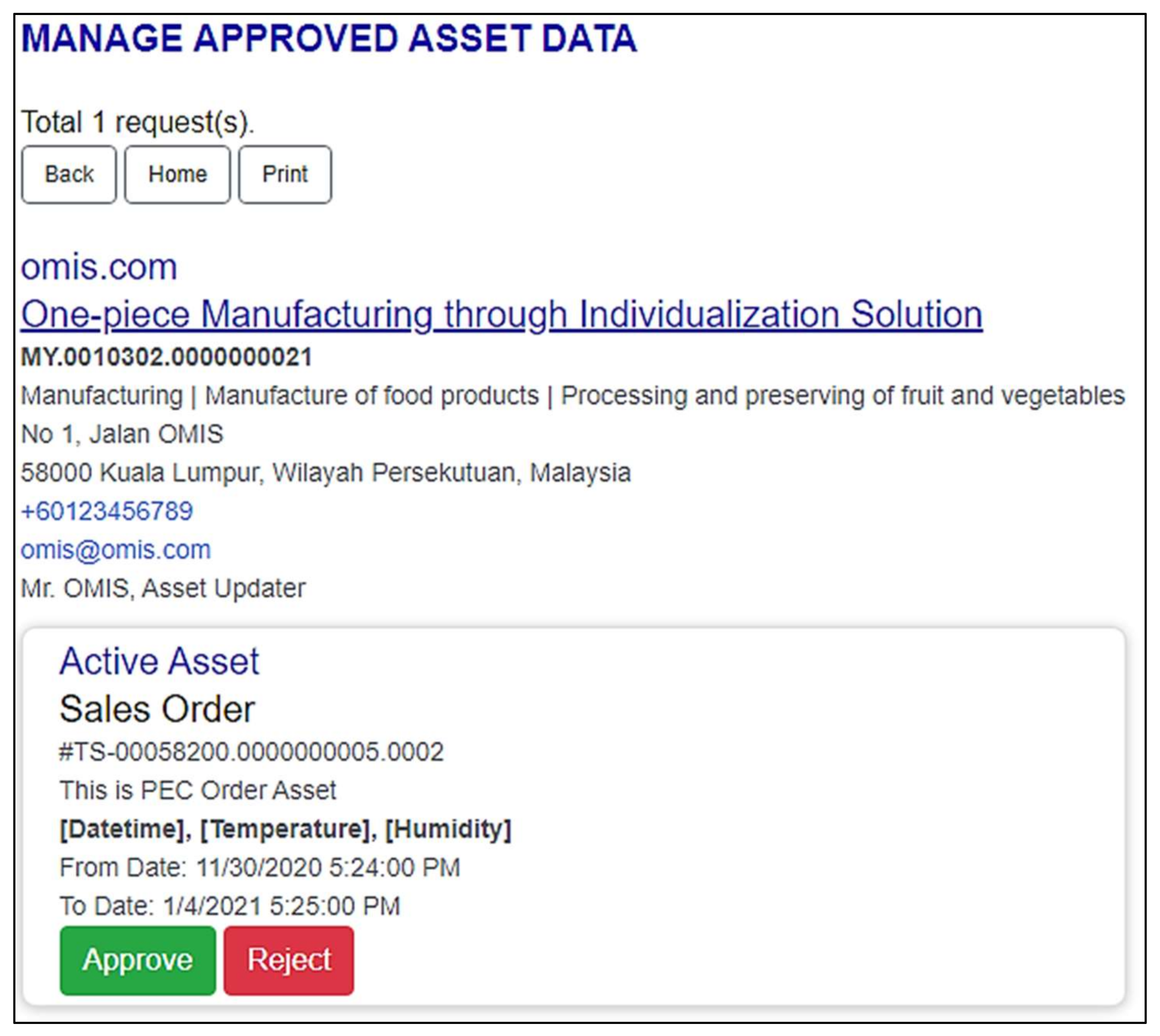
5.1. Testing the PEC AAdSys in Creating Assets and Instances

In the first test case, PEC is tested to create the “Sales Order” asset instances before the publishing of the asset to the ABM Portal, and before any data channeling between PEC and OMIS can be conducted. In the experiment, the generation of metadata of the “Sales Order” asset is successfully created; an example is shown in Figure 23. The “Sales Order” asset is maintained in the PEC AAdSys to be shared with OMIS in the next test case. A sample instance data of the “Sales Order” asset generated upon a new order by a PEC customer is shown in Figure 24. The creation of new instance data upon a new order and the data channeling event log between AAdSys and its Connector module are shown in Figure 25. Similarly, OMIS is also tested to generate the “Sales Order Status” asset. A sample of a “Sales Order Status” instance is shown in Figure 26. OMIS is the asset owner of the “Sales Order” Status asset, and PEC will be receiving it to update its web application to reflect the latest production status of the customers’ mixed-juice orders. In summary, all the necessary asset data are successfully generated based on the asset modeling design discussed in Section 4.1.

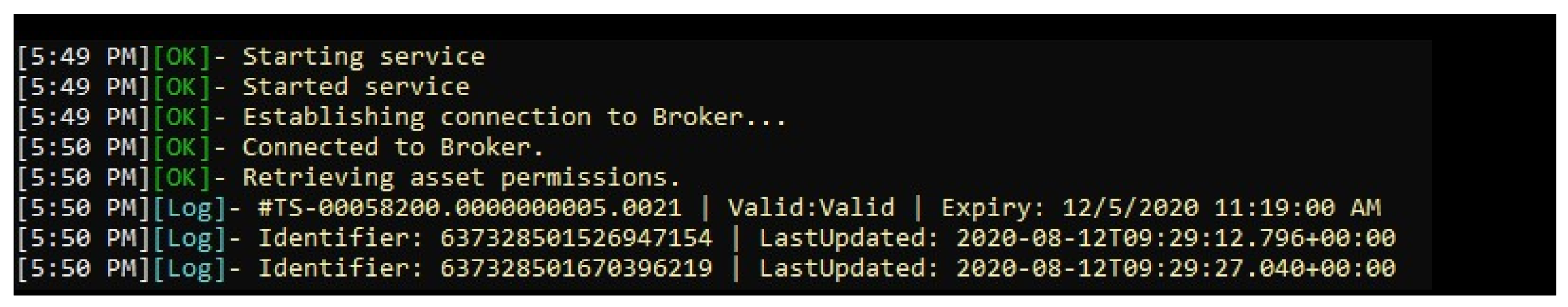
5.2. Connectivity Test between Asset Brokering Manager (ABM) Connector and ABM Portal

In the second test case, the ABM Portal is tested on the publishing of asset metadata through the AAdSys and the data channeling process. To test the success of the publication, the “Sales Order” asset metadata is published on the ABM Portal by PEC AAdSys. Figure 27 shows the results when searching for “PEC”; we are presented with their page on the ABM website. Data consumers, such as OMIS, can select the asset at the ABM Portal and choose a duration or date range of the subscription of the asset instance data, as shown in Figure 28.
Next, the data provider must approve the request of the asset data before the asset instance data can be channeled. The ABM Portal is expected to display the list of organizations awaiting approval of their requests. As shown in Figure 29, OMIS is on the waiting list, which can be viewed by the PEC administrator, who is the data provider; now, the PEC administrator can approve or reject the request.
Once the PEC administrator approves the OMIS request of the “Sales Order” asset data, the transferring of the asset data process shall begin according to the requested date range. According to this test case, a real-time instance data channeling request is created. Figure 30 and Figure 31 show the outputs of the real-time transaction logs between PEC and OMIS. The incoming data are verified to be correct, and the data are also successfully saved into the database. The output results also show that the data are channeled in real-time, with little to no delay from the PEC AAdSys to the OMIS AAdSys.

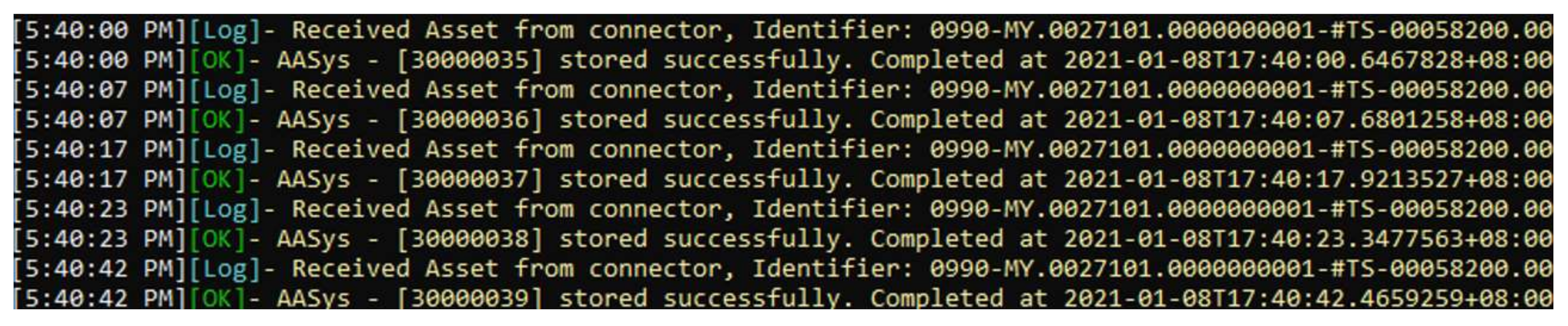
5.3. Connectivity Performance Test between Asset Administration Systems of PEC and OMIS

Testing of data channeling between the PEC AAdSys and OMIS AAdSys is conducted. Based on a total of 1000 sequential tests conducted each time, the connectivity from OMIS to PEC and vice versa are 100% successful, with the average time taken of 114 and 121 ms, respectively. The successful connectivity establishment is shown in Table 1.

6. Discussion and Conclusions

This paper demonstrates a method to create an asset data model based on the Asset Administration Shell and establishes value chain connectivity to channel the asset instance data from one enterprise to another using AAdSys. The entire development is designed based on RAMI 4.0. This method is implemented successfully in the POC for individualized mixed-juice production. The use case involves two stakeholders in a supply chain. First is the PEC, an online ordering system that instantly creates and models sales order data into a “Sales Order” asset format upon each customer’s order, simulating retailer enterprise activities. It also involves the OMIS highly automated manufacturing line for mass individualized mixed-juice production, simulating the Manufacturer enterprise. The OMIS contains different functions, such as receiving the instance data of the “Sales Order” asset for further production planning and execution, and self-generates the instance data of the “Sales Order Status” asset right after the completion of each production. The “Sales Order Status” asset is important for the PEC to update its customers that their orders are completed and ready for collection or shipment.
To enable horizontal value-chain integration, the POC involves two important components to allow secured data channeling, which are the Asset Brokering Manager (ABM) Connector and the ABM Portal. The ABM Connector interfaces with the ABM Portal through services built with Web APIs. Whenever there is an asset to be requested by the data consumer and approved by the data provider, the connection between the two relevant Connectors is established. In the time that the request is no longer valid, the connection can be either suspended or terminated. To allow the users of the applications to subscribe to the data belonging to the data provider, the ABM Portal is created to allow the data providers to publish their asset metadata to the portal. This horizontal integration concept can be extended to a longer value chain in the future. For instance, the OMIS Manufacturer can publish an asset called “Purchase Order”. The “Purchase Order” asset instance data can be generated whenever there is a need for raw material replenishment. Their suppliers can subscribe to this asset provided by OMIS, receive the purchase order in real-time, and prepare the quotation to the OMIS purchasing department instantly.
In conclusion, this paper has shown a developed, working POC applied to a real-world use case of individualization production. The use case demonstrates how an individualized order can be sent to a real manufacturing line to produce the on-demand order. The proposed communication architecture will be useful for seamless horizontal and vertical value chain integration, which helps achieve the mass production of individualized products in the manufacturing industry. However, the POC developed in this use case contains some limitations. First, this POC only involves one brokering manager; therefore, the ABM Portal can be a single point of failure. If the ABM Portal is down or shut down for maintenance, the ABM Connector sitting in the AAdSys will no longer be able to communicate with the ABM Portal, and, therefore, none of the data sharing transactions can be performed. For future works, there are plans to move various modules off the ABM Portal, such as authentication and APIs management, to respective microservices. This is to offload the requests going to a single ABM Portal, and distributing tasks to multiple services is believed to help increase the high availability and speed of data processing. It is also important to address some other technical issues such as availability, fault tolerance, services discovery, and optimization of the system’s performance in runtime by balancing between computing power and latency. Moreover, it is also crucial to have effective messaging techniques that could further improve the latency issue of microservices. Reactive microservices architecture is believed to achieve a fault-tolerant and fast data processing system, enabling value-chain integration and real-time data exchange, as recommended in RAMI 4.0 and IDS-RAM.
The second limitation is that this paper only focuses on the implementation of the integration, communication, and information layers of RAMI 4.0. The outcome of this research proposes an architecture that mainly addresses two major problems, which are (i) asset modeling and integration, (ii) data communication and brokering. Therefore, the experiments limit our focus to testing the creation of the data and the connectivity performance between two servers belonging to PEC and OMIS. This paper does not assess the efficiency of the system from the end-user’s perspective. It also does not test the performance of the physical manufacturing and delivery processes. More holistic research shall be developed in the future to assess the outcome of Industry 4.0 implementation based on RAMI 4.0. For instance, more research can be conducted to assess the manufacturing performance after the implementation of such architecture. This can include the assessment of the time performance of the goods received from a supplier and the time taken for the goods to be received by an end-user. The research can also include some studies related to product lifecycle and value stream mapping. In short, more future works can be carried out to test the implementation of other axes or layers of RAMI 4.0.

Author Contributions

Conceptualization, W.P.L. and Y.M.L.; methodology, J.H.H., D.S.C., Z.H.G., S.K.G.; software, J.H.H., D.S.C., Z.H.G.; writing—original draft preparation, J.H.H., D.S.C., Z.H.G., S.K.G.; writing—review and editing, Y.M.L.; visualization, J.H.H., D.S.C., Y.M.L.; supervision, W.P.L., Y.M.L., T.L.W., C.P.G.; funding acquisition, W.P.L., T.L.W. All authors have read and agreed to the published version of the manuscript.

Funding

This research is funded by the internal grant by Tunku Abdul Rahman University College (Grant No.#: UC/1/G2019-0043) and Asia Roofing Industries Sdn Bhd (Grant No.#: UC/IC/G2019-0013/3) under industry–academia collaboration in implementing Industry 4.0.

Institutional Review Board Statement

Not Applicable.

Informed Consent Statement

Not Applicable.

Data Availability Statement

Not Applicable.

Conflicts of Interest

The authors declare no conflict of interest.

References

  1. Zhang, X.; Ming, X.; Liu, Z.; Qu, Y.; Yin, D. State-of-the-art review of customer to business (C2B) model. Comput. Ind. Eng. 2019, 132, 207–222. [Google Scholar] [CrossRef]
  2. Torn, I.A.R.; Vaneker, T.H.J. Mass Personalization with Industry 4.0 by SMEs: A concept for collaborative networks. Procedia Manuf. 2019, 28, 135–141. [Google Scholar] [CrossRef]
  3. Koren, Y. The Global Manufacturing Revolution: Product-Process-Business Integration and Reconfigurable Systems; John Wiley & Sons: Hoboken, NJ, USA, 2010; Volume 80. [Google Scholar]
  4. Hankel, M.; Rexroth, B. The Reference Architectural Model Industrie 4.0 (Rami 4.0); ZVEI: Frankfurt am Main, Germany, 2015; Volume 2, pp. 4–9. [Google Scholar]
  5. Schweichhart, K. Reference Architectural Model Industrie 4.0 (Rami 4.0): Introduction. 2016, Volume 40. Available online: https://www.amnytt.no/getfile.php/3901260.2265.akzillql7uuipz/RAMEI+4.0.pdf (accessed on 6 December 2021).
  6. Adolphs, P.; Berlik, S.; Dorst, W.; Friedrich, J.; Gericke, C.; Hankel, M.; Heidel, R.; Hoffmeister, M.; Mosch, C.; Pichler, R.; et al. Reference Architecture Model Industrie 4.0 (RAMI 4.0), DIN SPEC 91345:2016-04. DIN. 2016. Available online: https://www.en-standard.eu/din-spec-91345-reference-architecture-model-industrie-4-0-rami4-0-4/ (accessed on 26 March 2020).
  7. Aheleroff, S.; Mostashiri, N.; Xu, X.; Zhong, R.Y. Mass Personalisation as a Service in Industry 4.0: A Resilient Response Case Study. Adv. Eng. Inform. 2021, 50, 101438. [Google Scholar] [CrossRef]
  8. Aheleroff, S.; Philip, R.; Zhong, R.Y.; Xu, X. The Degree of Mass Personalisation under Industry 4.0. Procedia CIRP 2019, 81, 1394–1399. [Google Scholar] [CrossRef]
  9. Wang, Y.; Ma, H.-S.; Yang, J.-H.; Wang, K.-S. Industry 4.0: A way from mass customization to mass personalization production. Adv. Manuf. 2017, 5, 311–320. [Google Scholar] [CrossRef]
  10. Hang, J.H.; Lee, W.P.; Lim, Y.M. Towards Mass Individualized Production: RAMI 4.0 Asset Data Channelling for Manufacturing Value Chain Connectivity. In Proceedings of the 2021 3rd International Conference on Computer Communication and the Internet (ICCCI), Nagoya, Japan, 25–27 June 2021; pp. 225–231. [Google Scholar] [CrossRef]
  11. Lee, W.P. The Way Forward for SMI/SMEs in Industry 4.0: Industry 4.0 in Germany & Malaysia; Urban Engineering Development Special Interest Group (UEDSIG), Mechanical Engineering Technical Division (METD), The Institution of Engineers: Petaling Jaya, Malaysia, 2019. [Google Scholar]
  12. Plattform Industrie 4.0. Plattform Industrie 4.0. Digital Transformation, ‘Made in Germany’, Berlin. 2016. Available online: https://ec.europa.eu/information_society/newsroom/image/document/2016-27/10__pi40_diemer_16494.pdf (accessed on 24 March 2019).
  13. SAP News Centre. Open Industry 4.0 Alliance: An Open Ecosystem for the Digital Transformation of Industrial Manufacturing Plants; SAP: Walldorf, Germany, 2019. [Google Scholar]
  14. Adolphs, P.; Auer, S.; Bedenbender, H.; Meik, B.; Martin, H.; Roland, H. Structure of the Administration Shell-Continuation of the Development of the Reference Model for the Industrie 4.0 Component. Berlin: Federal Ministry for Economic Affairs and Energy (BMWi). 2016. Available online: http://sf-eu.net/wp-content/uploads/2016/08/bmwi-2016-plattform-industrie-4.0-structure-of-the-administration-shell-en.pdf (accessed on 26 March 2020).
  15. DIN SPEC 91345; Reference Architecture Model Industrie 4.0 (RAMI4.0). Springer: Berlin/Heidelberg, Germany, 2016. [CrossRef]
  16. Rojko, A. Industry 4.0 Concept: Background and Overview. Int. J. Interact. Mob. Technol. 2017, 11, 77–90. [Google Scholar] [CrossRef] [Green Version]
  17. Zezulka, F.; Marcon, P.; Vesely, I.; Sajdl, O. Industry 4.0—An Introduction in the phenomenon. IFAC-PapersOnLine 2016, 49, 8–12. [Google Scholar] [CrossRef]
  18. Lin, S.-W.; Murphy, B.; Clauer, E.; Loewen, U.; Neubert, R.; Bachmann, G.; Hankel, M. Architecture Alignment and Interoperability. An Industrial Internet Consortium and Platform Industrie 4.0; White Paper; Industrial Internet Consortium: Boston, MA, USA, 2017; Volume 12, p. 19. [Google Scholar]
  19. Alcácer, V.; Cruz-Machado, V. Scanning the Industry 4.0: A Literature Review on Technologies for Manufacturing Systems. Eng. Sci. Technol. Int. J. 2019, 22, 899–919. [Google Scholar] [CrossRef]
  20. Plattform Industrie 4.0. Details of the Administration Shell—From Idea to Implementation [UPDATE]. 2019. Available online: https://www.plattform-i40.de/IP/Redaktion/EN/Downloads/Publikation/vws-in-detail-presentation.html (accessed on 28 November 2021).
  21. Chin, C.F.; Lim, Y.M.; Lee, W.P. Designing Automated Batch-Processing Production Planning for Manufacturing based on Asset-Oriented Modelling. In Proceedings of the International Conference on Digital Transformation and Applications, Kuala Lumpur, Malaysia, 14–16 January 2020; pp. 1–5. Available online: https://www.tarc.edu.my/icdxa/publication (accessed on 1 November 2021).
  22. Cavalieri, S.; Salafia, M.G. Asset Administration Shell for PLC Representation Based on IEC 61131–3. IEEE Access 2020, 8, 142606–142621. [Google Scholar] [CrossRef]
  23. Marcon, P.; Diedrich, C.; Zezulka, F. The Asset Administration Shell of Operator in the Platform of Industry 4.0. In Proceedings of the 2018 18th International Conference on Mechatronics-Mechatronika (ME), Brno, Czech Republic, 5–7 December 2018; pp. 1–5. [Google Scholar]
  24. Tantik, E.; Anderl, R. Integrated Data Model and Structure for the Asset Administration Shell in Industrie 4.0. Procedia CIRP 2017, 60, 86–91. [Google Scholar] [CrossRef]
  25. Wenger, M.; Zoitl, A.; Müller, T. Connecting PLCs With Their Asset Administration Shell for Automatic Device Configuration. In Proceedings of the 2018 IEEE 16th International Conference on Industrial Informatics (INDIN), Porto, Portugal, 18–20 July 2018; pp. 74–79. [Google Scholar] [CrossRef]
  26. Fuchs, J.; Schmidt, J.; Franke, J.; Rehman, K.; Sauer, M.; Karnouskos, S. I4.0-compliant integration of assets utilizing the Asset Administration Shell. In Proceedings of the 2019 24th IEEE International Conference on Emerging Technologies and Factory Automation (ETFA), Zaragoza, Spain, 10–13 September 2019; pp. 1243–1247. [Google Scholar] [CrossRef]
  27. Wagner, C.; Grothoff, J.; Epple, U.; Drath, R.; Malakuti, S.; Grüner, S.; Hoffmeister, M.; Zimermann, P. The role of the Industry 4.0 asset administration shell and the digital twin during the life cycle of a plant. In Proceedings of the 2017 22nd IEEE International Conference on Emerging Technologies and Factory Automation (ETFA), Limassol, Cyprus, 12–15 September 2017; pp. 1–8. [Google Scholar] [CrossRef]
  28. Kusiak, A. Smart manufacturing. Int. J. Prod. Res. 2017, 56, 508–517. [Google Scholar] [CrossRef]
  29. Plattform Industrie 4.0, Relationships between I4.0 Components—Composite Components and Smart Production: Continuation of the Development of the Reference Model for the I4.0 SG Models and Standards. Berlin: Federal Ministry for Economic Affairs and Energy (BMWi). 2017. Available online: https://www.plattform-i40.de/PI40/Redaktion/DE/Downloads/Publikation/hm-2018-relationship.pdf?__blob=publicationFile&v=5 (accessed on 15 December 2020).
  30. IEC. IEC 62832-1:2020|IEC Webstore. International Electrotechnical Commission. 2020. Available online: https://webstore.iec.ch/publication/65858 (accessed on 28 November 2021).
  31. Bedenbender, H.; Billmann, M.; Epple, U.; Hadlich, T.; Hankel, M.; Heidel, R.; Zinn, M. Examples of the Asset Administration Shell for Industrie 4.0 Components Basic Part; ZVEI: Frankfurt am Main, Germany, 2017; pp. 1–24. [Google Scholar]
  32. Otto, B.; Auer, S.; Cirullies, J.; Jürjens, J.; Menz, N.; Schon, J.; Wenzel, S. Industrial Data Space: Digital Souvereignity over Data; White paper; Fraunhofer-Gesellschaft: Munchen, Germany, 2016; pp. 1–39. [Google Scholar] [CrossRef]
  33. Alonso, A.; Huertas, A.P.; Cantera, J.; Vega, F.; Hierro, J. Industrial Data Space Architecture Implementation Using FIWARE. Sensors 2018, 18, 2226. [Google Scholar] [CrossRef] [PubMed] [Green Version]
  34. Otto, B.; Steinbuß, S.; Teuscher, A.; Lohmann, S. International Data Space Reference Architecture Model Version 3.0; International Data Spaces Association: Berlin, Germany, 2019; pp. 1–118. Available online: https://internationaldataspaces.org/wp-content/uploads/IDS-Reference-Architecture-Model-3.0-2019.pdf (accessed on 1 November 2021).
  35. Andreas Teuscher, A.; Gerd Brost, G.; Uwe Brettner, U.; Martin Böhmer, M.; Bastian Fraune, B.; Christian Haas, C.; Tina Hardt, T.; Benjamin Heidenreich, B.; Christian Jung, C.; Lutz Jänicke, L.; et al. DIN SPEC 27070:2020-03; Requirements and Reference Architecture of a Security Gateway for the Exchange of Industry Data and Services. DIN German Institute for Standardization: Berlin, Germany, 2020; pp. 1–26. [CrossRef]
  36. Erl, T. Service-Oriented Architecture: A Field Guide to Integrating XML and Web Services; Prentice Hall: Upper Saddle River, NJ, USA, 2004. [Google Scholar]
  37. Fowler, M.; Lewis, J. Microservices. 2014. Available online: https://martinfowler.com/articles/microservices.html (accessed on 11 July 2021).
  38. Xiao, Z.; Wijegunaratne, I.; Qiang, X. Reflections on SOA and Microservices. In Proceedings of the 2016 4th International Conference on Enterprise Systems (ES), Melbourne, Australia, 2–3 November 2016; pp. 60–67. [Google Scholar] [CrossRef]
  39. Santana, C.; Alencar, B.; Prazeres, C. Microservices: A mapping study for internet of things solutions. In Proceedings of the 2018 IEEE 17th International Symposium on Network Computing and Applications (NCA), Cambridge, MA, USA, 1–3 November 2018. [Google Scholar] [CrossRef]
  40. Li, F.; Luo, B.; Liu, P.; Lee, D.; Chu, C.-H. Enforcing Secure and Privacy-Preserving Information Brokering in Distributed Information Sharing. IEEE Trans. Inf. Forensics Secur. 2013, 8, 888–900. [Google Scholar] [CrossRef] [Green Version]
  41. Li, F.; Luo, B.; Liu, P.; Lee, D.; Mitra, P.; Lee, W.-C.; Chu, C.-H. In-broker access control: Towards efficient end-to-end performance of information brokerage systems. In Proceedings of the IEEE International Conference on Sensor Networks, Ubiquitous, and Trustworthy Computing (SUTC’06), Taichung, Taiwan, 5–7 June 2006; Volume 1, p. 8. [Google Scholar] [CrossRef]
  42. Peyton, L.; Doshi, C.; Hu, J.; Seguin, P. Information rich monitoring of interoperating services in privacy enabled B2B networks. Int. J. Adv. Media Commun. 2010, 4, 258–273. [Google Scholar] [CrossRef]
  43. Xu, J.; Wei, L.; Wu, W.; Wang, A.; Zhang, Y.; Zhou, F. Privacy-preserving data integrity verification by using lightweight streaming authenticated data structures for healthcare cyber–physical system. Future Gener. Comput. Syst. 2018, 108, 1287–1296. [Google Scholar] [CrossRef]
  44. Office for Civil Rights. The HIPAA Privacy Rule. HHS.gov. 7 May 2008. Available online: https://www.hhs.gov/hipaa/for-professionals/privacy/index.html (accessed on 7 December 2021).
  45. Object Management Group (OMG). Information Exchange Framework Reference Architecture, 1st ed.; Object Management Group, Inc.: Milford, MA, USA, 2019. [Google Scholar]
  46. Object Management Group (OMG). Information Exchange Framework (IEF); Object Management Group, Inc.: Milford, MA, USA; Available online: https://www.omg.org/ief/index.htm (accessed on 28 November 2021).
  47. Charles, D.S.; Wong, T.L.; Lim, Y.M.; Lee, W.P. Towards Personalised Manufacturing with Industry 4.0: Asset Brokering in Real Time; UNTAR: Jakarta, Indonesia, 2021; pp. 1–6. [Google Scholar]
Figure 1. Reference architecture model for Industrie 4.0 (RAMI 4.0) [12].
Information 13 00056 g001
Figure 2. RAMI 4.0 Communication Layers mapped to the ISO/OSI Model [18].
Information 13 00056 g002
Figure 3. Structure of the Asset Administration Shell.
Information 13 00056 g003
Figure 4. Interaction of the technical components in IDS [34].
Information 13 00056 g004
Figure 5. Trusted Connector of the IDS (https://industrial-data-space.github.io/trusted-connector-documentation/docs/overview/) (accessed on 6 December 2021).
Information 13 00056 g005
Figure 6. The architecture diagram of proof-of-concept development.
Information 13 00056 g006
Figure 7. Overview of asset data communication architecture.
Information 13 00056 g007
Figure 8. The PEC online ordering application.
Information 13 00056 g008
Figure 9. The architecture of OMIS manufacturing processes.
Information 13 00056 g009
Figure 10. The top view of the OMIS juice manufacturing line.
Information 13 00056 g010
Figure 11. The physical OMIS manufacturing line.
Information 13 00056 g011
Figure 12. Gateway in the Asset Administration System between different organizations.
Information 13 00056 g012
Figure 13. Communication architecture for the PEC–OMIS data exchange ecosystem.
Information 13 00056 g013
Figure 14. AAdSys Framework.
Information 13 00056 g014
Figure 15. Asset model in the AAdSys AAS common library.
Information 13 00056 g015
Figure 16. Example of juice asset wrapped in the Asset Administration Shell format.
Information 13 00056 g016
Figure 17. Class diagram that represents the “Sales Order” asset.
Information 13 00056 g017
Figure 18. The infrastructure diagram of the connectivity setup between PEC and OMIS.
Information 13 00056 g018
Figure 19. Example of assets published on the ABM Portal.
Information 13 00056 g019
Figure 20. Real-Time data transfer between Data Provider and Data Consumer.
Information 13 00056 g020
Figure 21. File transfer from Data Provider to Data Consumer.
Information 13 00056 g021
Figure 22. Historical data transfer between Data Provider and Data Consumer.
Information 13 00056 g022
Figure 23. Metadata of the “Sales Order” asset.
Information 13 00056 g023
Figure 24. Instance data of the “Sales Order” asset.
Information 13 00056 g024
Figure 25. Output log on the Asset Administration System at the OMIS Line.
Information 13 00056 g025
Figure 26. “Sales Order Status” asset generated by OMIS AAdSys.
Information 13 00056 g026
Figure 27. Output of the search results when viewing PEC’s assets.
Information 13 00056 g027
Figure 28. Choosing date range for selected asset.
Information 13 00056 g028
Figure 29. PEC administrator’s view when OMIS requests an asset.
Information 13 00056 g029
Figure 30. Output during Real Time Transfer.
Information 13 00056 g030
Figure 31. Instance data for “Sales Order” asset on new order created by the Asset Administration System.
Information 13 00056 g031
Table 1. Asset Administration Systems connectivity test.
Data SizeConnectivity Test
FromToAverage Time (ms)
100 kbOMIS (Manufacturer)PEC (Retailer)114
100 kbPEC (Retailer)OMIS (Manufacturer)121
Publisher’s Note: MDPI stays neutral with regard to jurisdictional claims in published maps and institutional affiliations.

