Article

Cybersecurity Comparison of Brain-Based Automotive Electrical and Electronic Architectures

by
Nadera Sultana Tany
1,
Sunish Suresh
2,
Durgesh Nandan Sinha
2,
Chinmay Shinde
2,
Cristina Stolojescu-Crisan
3,* and
Rahamatullah Khondoker
4
1
AG Information Management (AGIM), Faculty of Mathematics and Computer Science, University of Bremen, 28359 Bremen, Germany
2
Department of Control, Computer and Communications Engineering (CCCE), Faculty of Information Technology, Electronics, Mechatronics (IEM), Technische Hochschule Mittelhessen (THM) University of Applied Sciences, 61169 Friedberg, Germany
3
Communications Department, Faculty of Electronics, Telecommunications, and Information Technology, Politehnica University of Timisoara, Bd. Vasile Pârvan, nr. 2, 300223 Timisoara, Romania
4
Department of Business Informatics, Faculty of Mathematics, Natural Science & Data Processing (MND), THM University of Applied Sciences, 61169 Friedberg, Germany
*
Author to whom correspondence should be addressed.
Submission received: 31 August 2022 / Revised: 30 September 2022 / Accepted: 3 October 2022 / Published: 31 October 2022
(This article belongs to the Special Issue Automotive System Security: Recent Advances and Challenges)

Abstract

:
Modern autonomous vehicles with an electric/electronic (E/E) architecture represent the next big step in the automation and evolution of smart and self-driving vehicles. This technology is of significant interest nowadays and humans are currently witnessing the development of the different levels of automation for their vehicles. According to recent demand, the components of smart vehicles are centrally or zonally connected, as well as connected to clouds to ensure the seamless automation of driving functions. This necessity has a downside, as it makes the system vulnerable to malicious attacks from hackers with unethical motives. To ensure the control, safety, and security of smart vehicles, attaining and upholding automotive cybersecurity standards is inevitable. The ISO/SAE 21434 Road vehicle—Cybersecurity engineering standard document was published in 2021 and can be considered the Bible of automotive cybersecurity. In this paper, a comparison between four different E/E architectures was made based on the aforementioned standard. One of them is the traditional distributed architecture with many electronic control units (ECUs). The other three architectures consist of centralized or zonally distributed high-performance computers (HPCs). As the complexity of autonomous E/E systems are on the rise, the traditional distributive method is compared against the HPC (brain)-based architectures to visualize a comparative scenario between the architectures. The authors of this paper analyzed the threats and damage scenarios of the architectures using the ISO/SAE 21434 standard, “Microsoft Threat Analysis Tool - STRIDE”, TARA, and “Ansys Medini Analyze”. Security controls are recommended to mitigate the threats and risks in all of these studied architectures. This work attempted to mitigate the gap in the scholarly literature by creating a comparative image of the E/E architectures on a generalized level. The exploratory method of this research provides the reader with knowledge on four different architecture types, their fundamental properties, advantages, and disadvantages along with a general overview of the threats and vulnerabilities associated with each in light of the ISO/SAE 21434 standard. The improvement possibilities of the studied architectures are provided and their advantages and disadvantages are highlighted herein.

1. Introduction

The production technology of automotive vehicles has experienced a radical improvement due to digitization. Therefore, it is not surprising that we are the ones that shall experience the changeover of the mobility archetype as we know it today. In the future, the next generations will be able to drive very complex and advanced cyber-physical systems. With the flexibility of evolution, every design will require constant inspection, monitoring, and improvement to meet safety and security standards [1]. Even though typical security concepts are implemented in the fabrication of the vehicle, several architectures can fulfill the desired role for efficiency and security targets.
Today’s E/E architectures [2] are reaching their limits due to the increased system complexity and increased functionality. An existing in-vehicle E/E system can be cleaned up using a server/zone architecture. Reducing the multiple stand-alone ECUs and wiring harness allows the optimization of the overall architecture while reducing the weight and carbon emission. HPC offers faster and higher data processing and data security features [3] which is more familiar in the IT industry than in traditional vehicle architectures. A new level of computing power and the consistent separation between hardware and software are paving the way for new functions for traditional [4,5] and convenient over-the-air updates for HPC-based brain architectures [6,7]. Researchers are focusing on the different aspects of network communication protocols and ensure security during the over-the-air software update and upgrading process using modern technologies such as block-chain, machine learning, artificial intelligence, and many more [8].
This paper examines the various features of the automotive E/E architecture in addition to the components used in the vehicle design. The results show several advantages and disadvantages for the users, as well as for the overall fabrication of the vehicle. The Microsoft Threat Modeling Tool 2016 [9] can be used to study cybersecurity threat cases, threat scenarios, and damage scenarios by performing STRIDE analysis [10] within the framework of the traditional and HPC-based architectures. A use case describes the role of the different components in the design. Threat analysis by designers and manufacturers can help to improve vehicle system architectures, making security more effective and regularly reviewing them for more updates and changes.
  • This work explores the existing traditional, one-brain, two-brain, and three-brain E/E architectures available in the automotive industry;
  • The authors addressed the gap in the literature by providing a generic comparison between the architectures;
  • The four architectures are further analyzed in terms of vulnerability and the associated risks, according to the ISO/SAE 21434 standard Joint collaboration [11];
  • TARA methods are explored and analyzed the studied architectures with the MS Threat Modeling Tool - STRIDE and Ansys Medini Analyze tool [12];
  • The results of the analysis are presented through tables titled “Comparison Representation of Different E/E Architectures” and “Comparison of Cybersecurity Against the Number of Threats”.

2. Methodology

The goal of this study was to explore and analyze the existing automotive E/E architecture-based knowledge in order to create a generalized comparative image of current ECU- and HPC-based vehicle cybersecurity systems. An exploratory research approach was conceived with a combination of architecture-type-specific case studies in order to accomplish this task. In the case study part, a risk and threat analysis of the architectures was conducted using TARA and STRIDE methods. This part was accomplished using the MS Threat analysis tools [9] and Ansys Medini Analyze tools [12] according to the ISO/SAE 21434 standard [11]. The research methodology was a combination of exploratory research with case studies.
This article investigated four different architecture patterns in vehicles and for each architecture, the threats posed by three different functions (a combination of sensors and actuators) were examined using STRIDE. This article investigated the traditional architecture, the one-brain architecture, the two-brain architecture, and the three-brain architecture based on three functions, namely the tire pressure monitoring system (TPMS), the advanced driver-assistance system (ADAS), and the remote keyless entry system (RKE). Three functions were chosen so that the three brains could have at least one function for each brain and each function was a combination of sensors and actuators. The block diagram for each of the architectures was constructed using the Ansys Medini Analyze tool. This tool offers various blocks such as process, interactor, data flow, and data store. It also has the option to select various threats based on the block used, for instance, a controller which is a process having all six STRIDE threats (spoofing, tampering, repudiation, information disclosure, denial of service, and elevation of privilege). Based on this calculation, the various threats for an architecture were calculated. The threats from STRIDE helped determine damage scenarios. This approach is in accordance with TARA (ISO/SAE 21434) [11].
The threat was averaged and can be used as a reference to calculate the threats by 800 functions in a vehicle. Then, the threats for all four architectures were compared. The “number of threats” is one of the most important parameters and helps analyze architectures. Furthermore, based on the results, a common mathematical equation was formulated to calculate threats for any architecture pattern.
Additionally, the advantages and disadvantages are discussed with regard to cybersecurity critical functions for all three architectures and a qualitative comparison table is generated. This comparison table, along with the above formulated formula for threats, are the benchmark for recommending architectures for the automotive industry.

3. Background

3.1. ISO/SAE 21434

This standard defines the vocabulary, objectives, requirements, and guidelines related to cybersecurity engineering, as a foundation for common understanding throughout the supply chain. This enables different organizations to define cybersecurity protocols, policies and processes, the cybersecurity risk management, and fosters a cybersecurity culture on every level of the process.
The ground objectives of this document is to define an item, its operational environment, and the interactions with respect to cybersecurity. Furthermore, the cybersecurity goals, cybersecurity claims, and cybersecurity concept to achieve the defined goals must be specified.
  • Item definition
A standalone system or a group of components in an automotive environment which may possess vulnerabilities when interacting with the Internet or an external environment falls under this clause.
  • Cybersecurity goals
The concept-level cybersecurity requirement is associated with one or more threat scenarios for an item. The process to achieve the cybersecurity requirements is to perform a security analysis called Threat Analysis and Risk Assessment (TARA) using methods and tools like Microsoft STRIDE and/or Attack Tree and Microsoft Threat Modeling Tool and/or Medini Analyze which have been explained in (ISO/SAE 21434) [11].
  • Threat Analysis and Risk Assessment (TARA) Method
The concept phase of TARA is carried out by identifying the assets, identifying the corresponding damage scenarios, calculating the impact rating, identifying the threat scenarios, drafting the attack path analysis, determining the attack feasibility rating, the risk values, and risk treatment decisions. The major advantage of TARA is that each step identified in this process is independent and can be performed in any order.
One of the TARA methods was developed by security experts from Intel Security and is based on three groups of collected data, denoted as libraries:
  • Threat Agent Library (TAL)—lists all relevant threat agents and their corresponding attributes;
  • Methods and Objectives Library (MOL)—lists methods that each threat agent might employ along with a corresponding impact level;
  • Common Exposure Library (CEL)—lists areas of the greatest exposure and vulnerability.
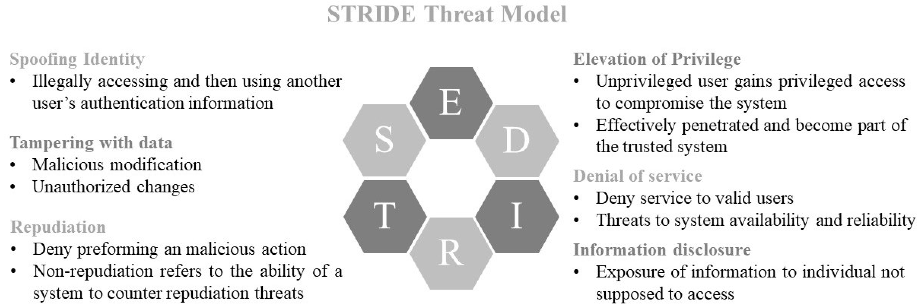
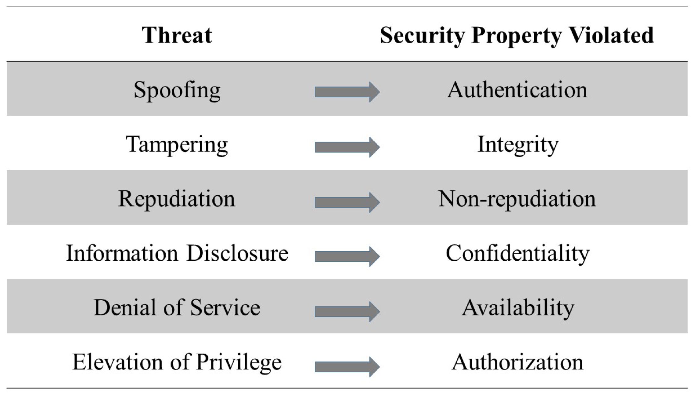
The individual tasks will be defined when TARA is applied to different architectures.

3.2. STRIDE

The STRIDE method was originally developed by Microsoft [9]. Figure 1 represents the STRIDE threat model.
This method allows threat identification in every development life cycle phase starting from the design phase of any software or hardware (see Figure 2) and thus, gives insights into potential attack scenarios.
There are two variants of the STRIDE method to derive threats automatically, namely per-interaction and per-element and these methods have been implemented by Medini Analyze.

3.3. Model and Associated Threats
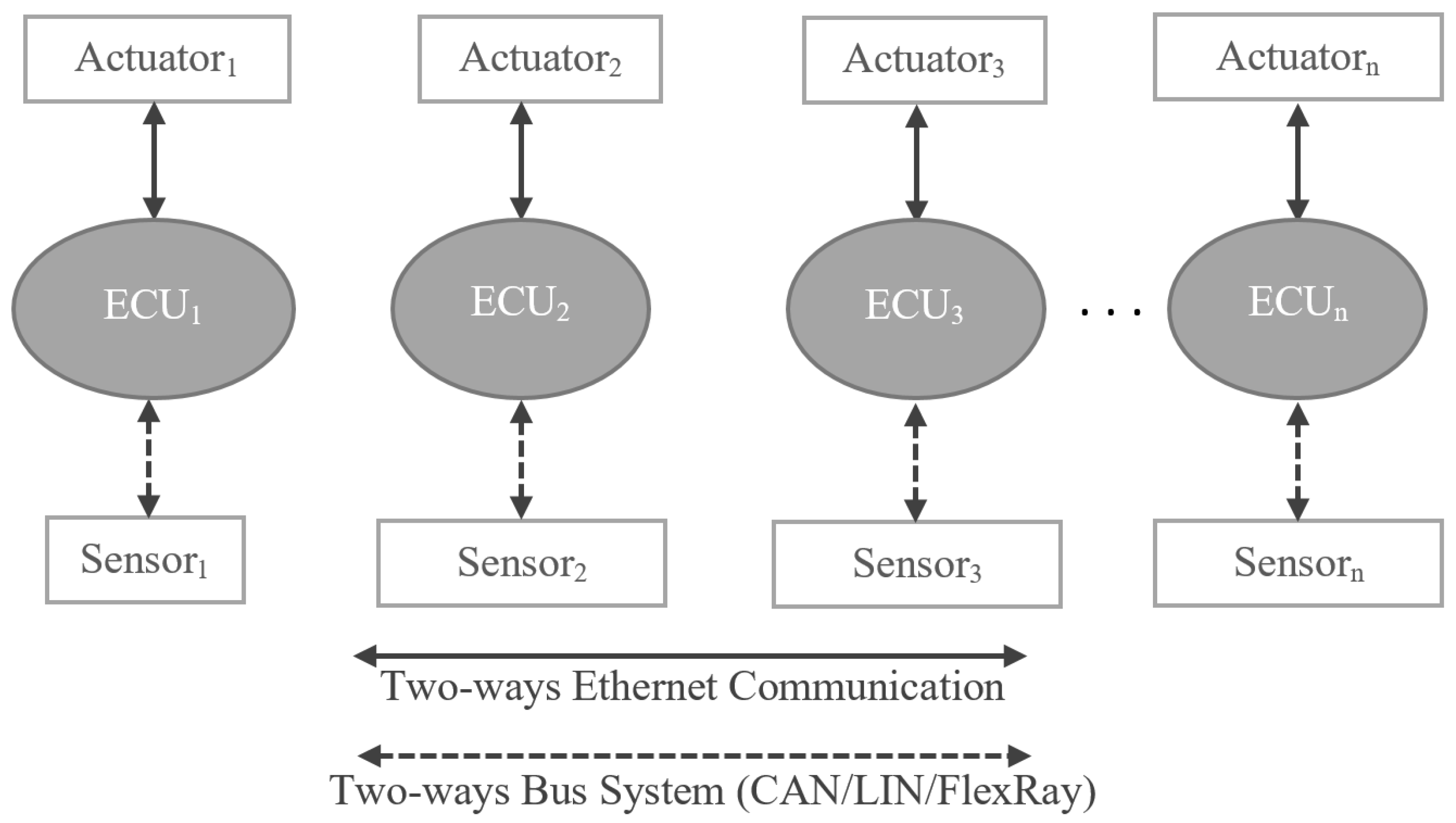
Each component of an E/E system can be analyzed using the STRIDE method and each one of them has a list of threat categories and is exposed to one or more threats of each category. Figure 3 shows the association between a model and the possible threat categories. As shown in Figure 3, a process is exposed to all six threat categories, an interactor is exposed to two threat categories, a data flow in one direction is exposed to three threat categories, and a data store is exposed to three threat categories. A component can have one or more threats in one category.

4. Architectures

Due to the demands of innovative applications in autonomous driving scenarios, automotive industries are moving forwards from traditional to smart architectures. In this work, four E/E architectures were investigated. These architectures are named traditional architecture, one-brain architecture, two-brain architecture, and three-brain architecture. Their design construction possibilities are described, respectively, in the following part of this article.

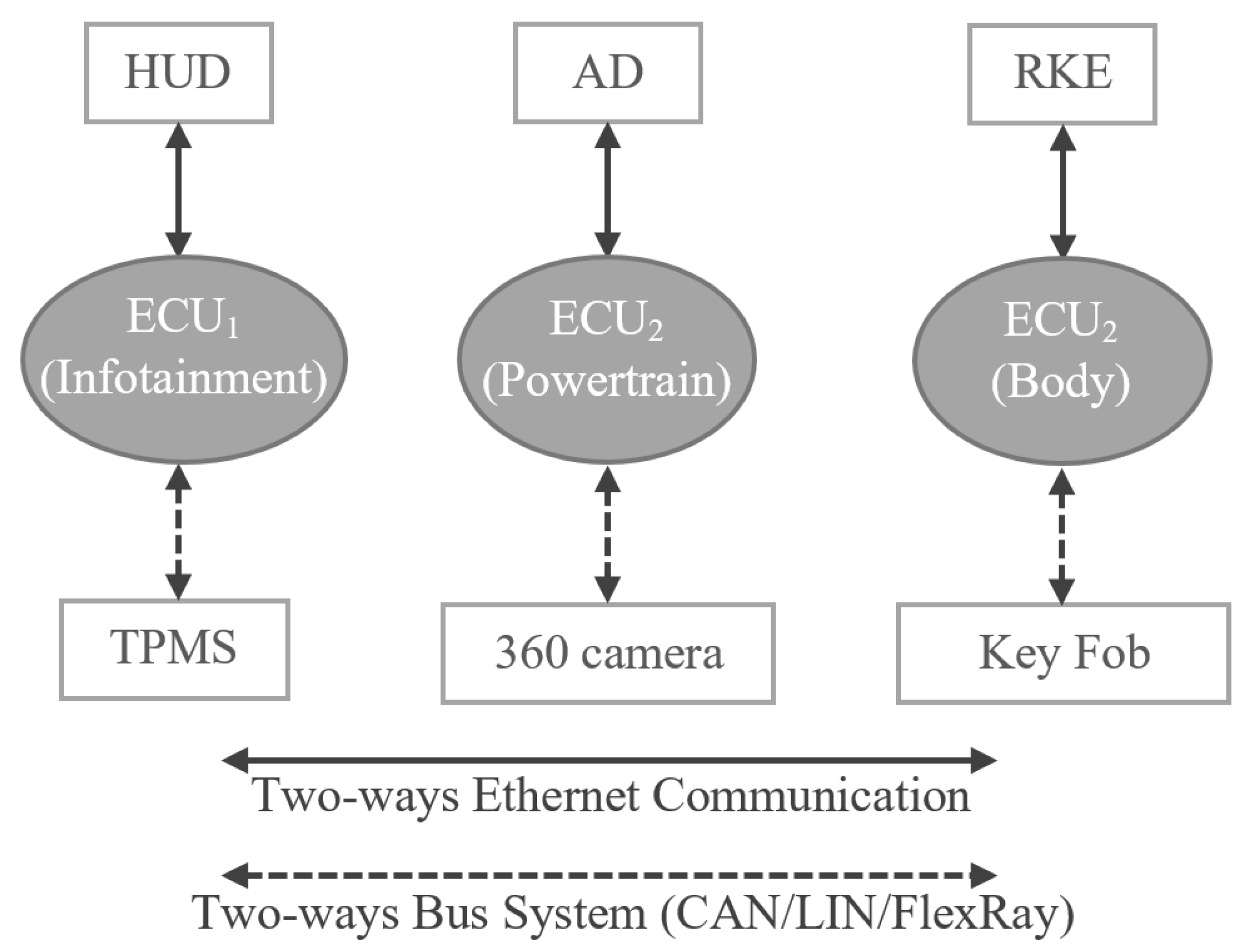
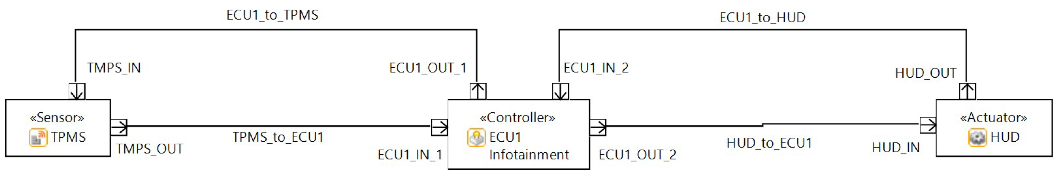
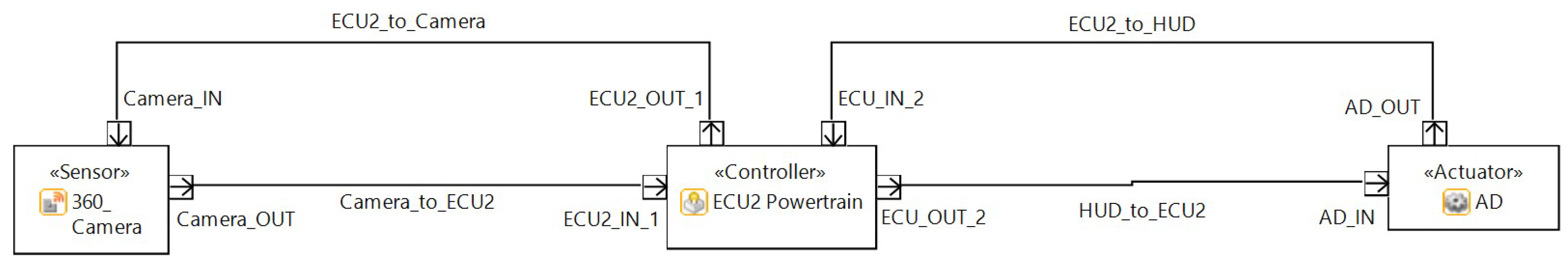
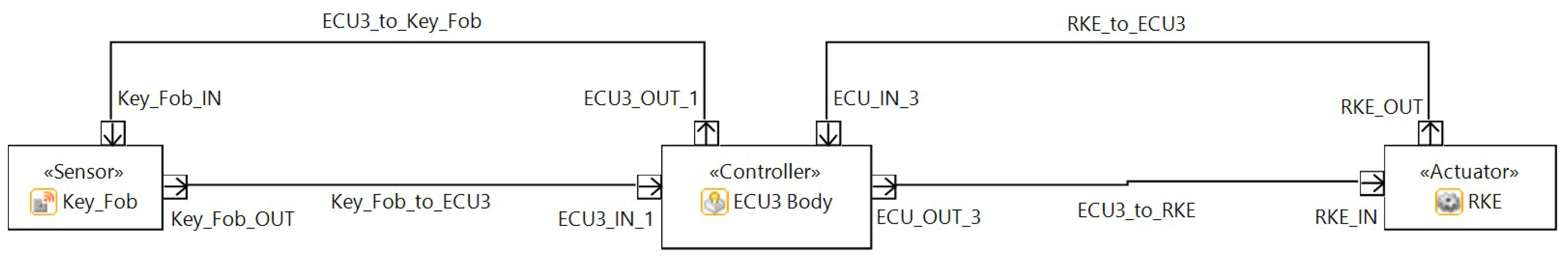
4.1. Traditional E/E Architecture

The traditional architecture (shown in Figure 4) is an approach where vehicle functions, such as infotainment and powertrain, are processed usually by individual ECUs and those ECUs are organized in a distributed manner within the car.
As shown in Figure 4, the traditional architecture consists of the ECUs and interactors (sensors and actuators). One ECU hosts normally one function in a traditional architecture, however, is able to host more than one function. In this article, we assume that each ECU hosts up to eight functions. The ECU receives input sensing data from the connected sensors and sends the actuation signal to the actuators, based on the logic implemented in the ECU. In the traditional architecture, communication between the ECU and the sensor is achieved using a two-way bus system (CAN/LIN/FlexRay) and communication between the ECU and the actuator is achieved using two-way Ethernet cables or bus system. In this article, we assume that Ethernet cables are connected between the ECUs and actuators and bus system is connected between the ECUs and sensors.
  • Use Case:
The architecture for different use cases and the connections between the ECUs and the interactors are illustrated in Figure 5. The threat modeling of the traditional architecture for different ECUs, along with their functions and interactors are drawn using Medini Analyze and are shown in Figure 6, Figure 7 and Figure 8.
  • Tire Pressure Monitoring System
The Tire Pressure Monitoring Sensor (TPMS) senses the pressure in a tire and sends the data to the ECU, which is further processed and real-time data are provided to the Head Unit Display (HUD). The information displayed on the HUD is useful to avoid accidents in case of, for example, low pressure or flat tires.
  • Advanced Driver Assistance System (ADAS)
The 360 camera systems are the backbone for Autonomous Driving (AD) and the image data received from the camera are processed by the connected ECU in order to understand the external environment to take precise decisions during driving the car autonomously.
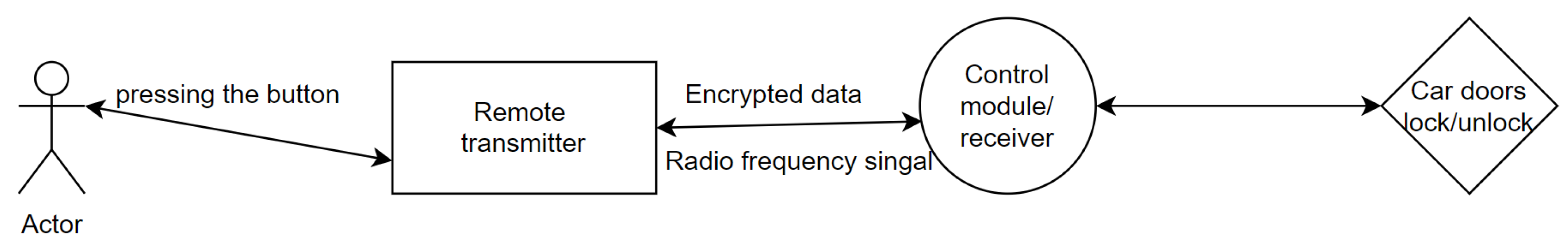
  • Remote Keyless Entry System (RKE)
A RKE system consists of a keyfob (which is able to send/receive low range signals) and a signal receiver located in the door control module (DCM) of a car. In the active RKE, the buttons are dedicated to locking or unlocking the doors and opening the trunk or tailgate. In the passive RKE, so called a smart keyfob, no active action to press the button is required, rather signal proximity is used to open/close the door. The functionality of the key fob is illustrated in Figure 9. When the user presses a button, the key fob will send the signal that will be processed by the ECU so called Door Control Module (DCM). If the signal transmitted from the key fob matches what the DCM is programmed to accept, the DCM will send a command to the actuators which will open the door.
When a user presses a remote button, the transmitter sends an encrypted radio frequency signal to the control module/receiver and then it triggers the relay which opens/closes the doors. Every vehicle has its own radio frequencies, so the data are always encrypted and one cannot open the vehicle without a given keyfob.
  • Advantages of the low performance Electronic Control Unit (ECU) in a traditional architecture:
    • If one ECU is attacked, the functions hosted by that particular ECU are affected where the number of functions is low. However, in case of an attack on HPCs, as many functions are involved, the damage is more serious.
    • ECU is easy to develop and maintain as it usually has low performance and hosts few functions.
    • In case of a damage of an ECU, it is easier to replace due to its low-performance capability.
  • Drawbacks of an Electronic Control Unit (ECU) in a traditional architecture:
    • The performance is very low (100 or 1000 times) compared to high performance computing devices like HPCs and host few functions.
    • When low-performance ECUs are used, many ECUs are required to provide all the functions necessary for a car, which are difficult to maintain.
    • Connecting so many ECUs requires wires. Therefore, wiring harness in a high end car is around 10 km long when connecting all cables one after another, producing high energy consumption to carry the heavy cables. In addition, the complex topology of the cable connectivity makes it difficult to maintain and repair in case of a connection failure.

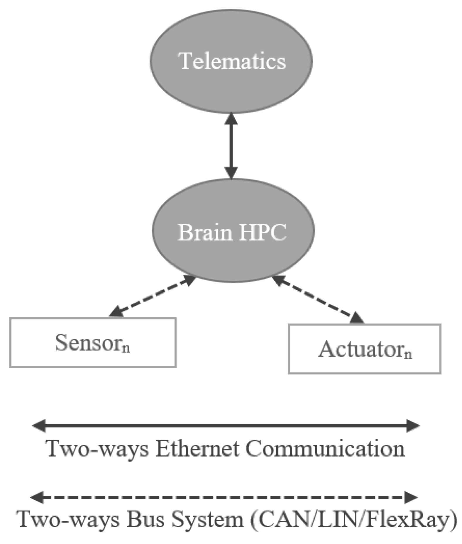
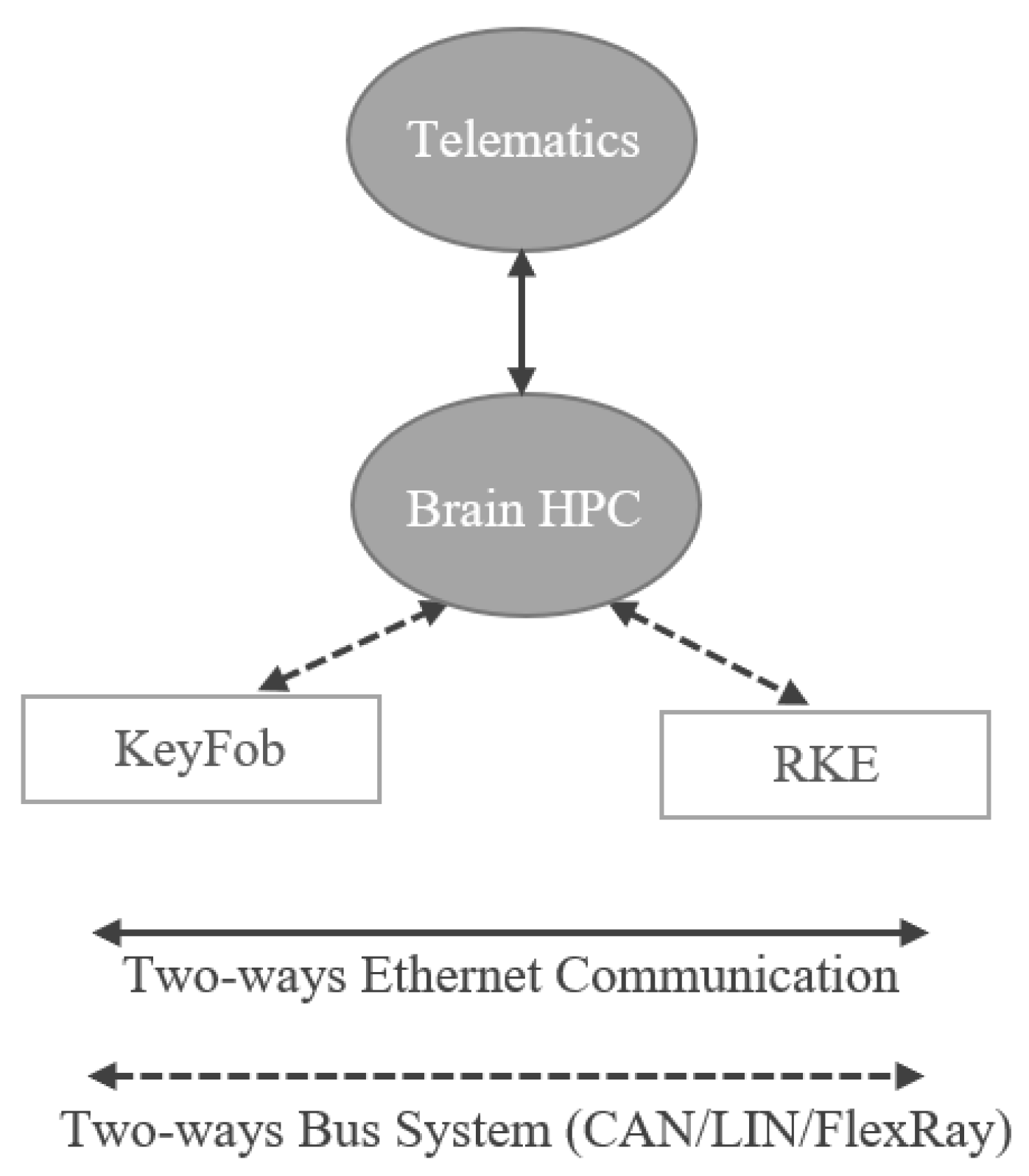
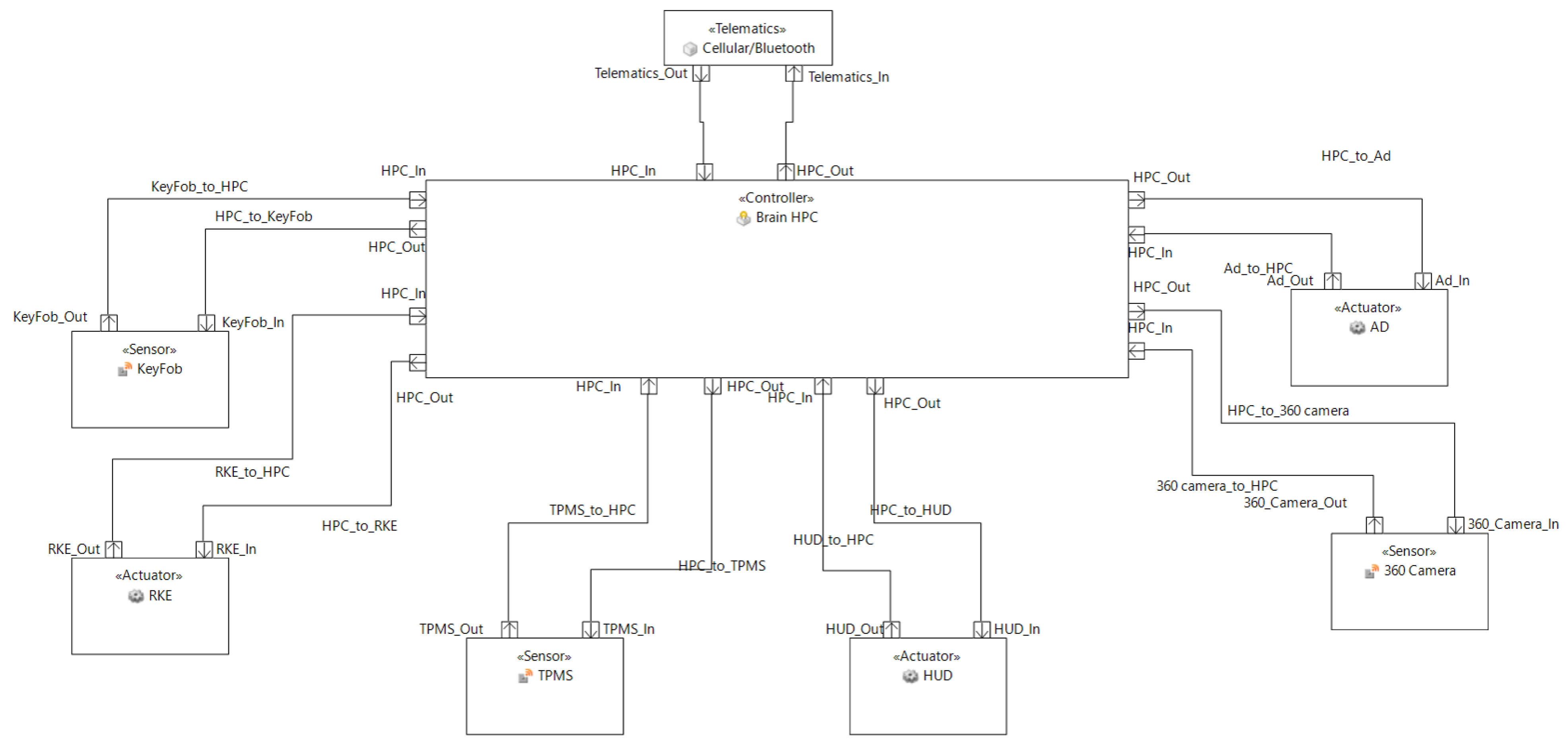
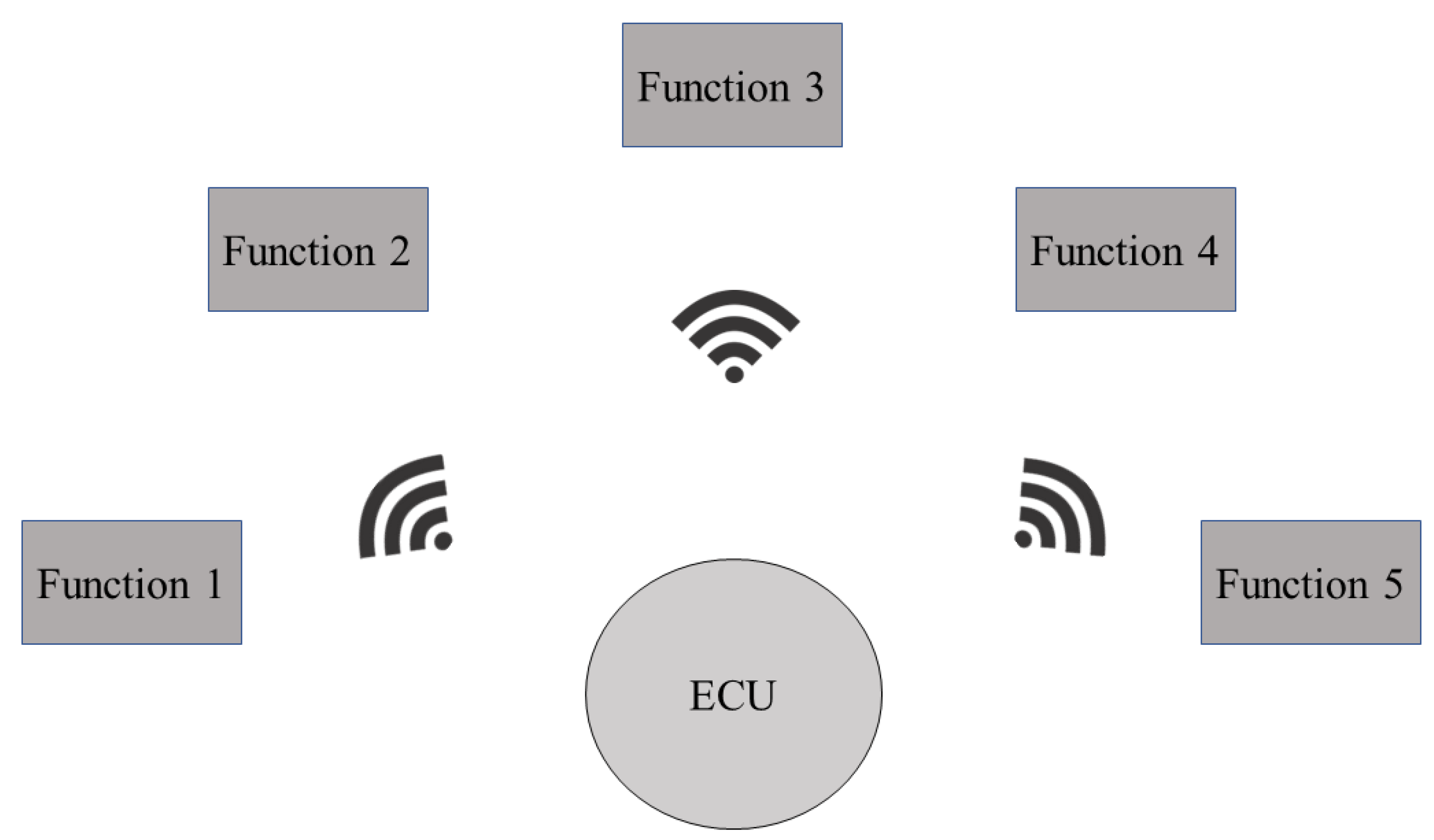
4.2. One-Brain (Centralized) E/E Architecture

“One-brain architecture” is the name given to the approach where modern vehicle functions (estimated at approximately 800) are processed using an High Performance Computing (HPC) platform, which is further connected to the telematics unit. Other names for this architecture are Centralized Architecture, HPC architecture, One-Brain Architecture, in short, Brain Architecture.
In the One-Brain E/E architecture (as shown in Figure 10), there will be a single and centralized HPC, instead of distributed ECUs as seen in the traditional architecture.
In the conventional design of an in-vehicle automotive architecture, there are multiple low-performance ECUs for individual tasks and all of them are then connected individually. Besides having difficulties of managing so many individual ECUs, the introduction of new functionalities and infrastructures such as Vehicle to Everything (V2X), Advanced Driver Assistance System (ADAS)/Autonomous Driving (AD) and the Internet of Things (IoT) in the vehicles require a shift from the old distributed control system to a centralized high-performance architecture like One-Brain.
The One-Brain architecture is depicted with a use case representing the connections between the centralized “Brain HPC” and the related sensors and interactors such as KeyFob, RKE, and Telematics are illustrated in Figure 11.
  • Use Case:
The threat modeling of One-Brain architecture for the above mentioned use case is realized using Medini Analyze as shown in Figure 12.
  • Advantages of One-Brain Architecture:
    • It is cheaper than multiple individual ECUs when the price of Brain-HPC is cheaper than the cost of all the ECUs and the funtions hosted on those ECUs.
    • The complexity of the whole in-vehicle E/E architecture is reduced due to centralization of the functionalities.
    • It can handle high computing, which is required for ADAS, IoT, and other high-computing applications.
    • Since such a Brain-HPC has several high and low performance cores, each of the cores is able to host one vertical stack representing an Virtualization layer, Operating System (OS) layer, Middleware, and applications.
    • Able to provide decoupling of functionalities. For example, safety cores (which are able to host safety functions) are separated from the high performance cores (providing Infotainment functionalities).
  • Disadvantages of One-Brain Architecture:
    • Earlier handling of the hardware/software architecture is required. The hardware and software architecture should be defined during the concept phase of the vehicle. For example, the performance requirement of the HPC (Memory Capacity, Number of Cores, Number of Boards, etc.) needs to be calculated considering the number of functions to be hosted on the HPC in the future, which is sometimes difficult to predict.
    • Since this is new type of architecture, all of the stakeholders (OEM, Tier1 Supplier, Tier2 Supplier) who are involved in the development of the architecture need to understand the architecture in detail. This requires a huge communication overhead.
    • The failure of the centralized Brain will lead to the whole vehicle to be non-functional.

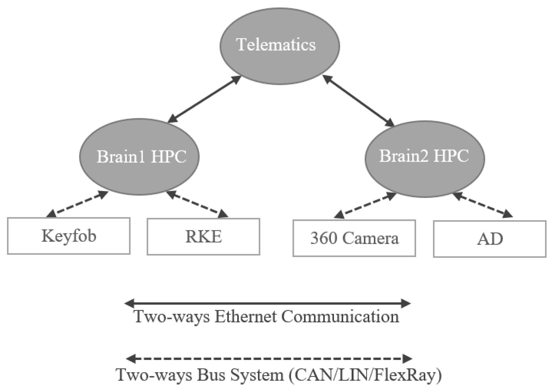
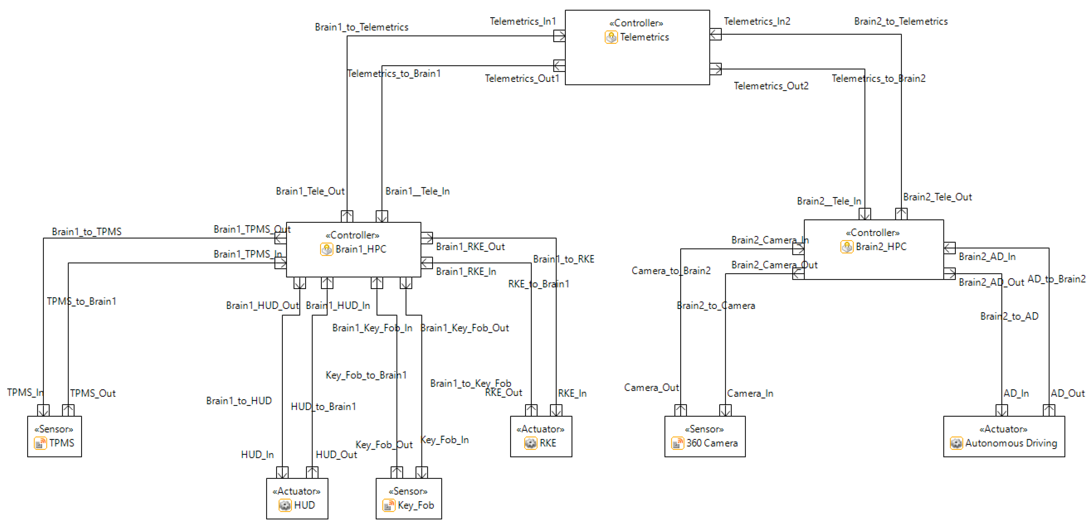
4.3. Two-Brain (Zonal) E/E Architecture

The two-brain architecture is the name given to the approach where modern vehicle functions (estimated at approximately 800) are evenly distributed on two HPCs. Each of these HPCs are further connected to telematics. The typical representation of the two-brain architecture is presented in Figure 13. Whenever, the architecture having more than one HPCs is sometimes referred to as Zonal architecture. The reason for the name is that, it is necessary to define the exact place of the vehicle to deploy the HPC due to its size and weight requirements. Possible places to deploy the HPCs of the two-brain architectures are the front left and the front right side of the vehicle. Some OEMs use the term Zonal architecture to refer to the placement of the ECUs (left front, right front, left back, right back, and center/roof to manage the local sensors and actuators) which are then connected to the HPCs.
The architecture can have many sensors and actuators evenly distributed on a load capacity basis to two HPCs either directly connected to HPCs or connnected through ECUs in between.
  • Use Case:
The use case of two-brain architecture is shown in Figure 14 where RKE function is provided by Brain1 HPC and Autonomous Driving (AD) function is provided by Brain2 HPC. For providing RKE function, Brain1 HPC needs to interact with the Keyfob. To provide AD function, Brain2 HPC needs to interact with the 360 camera. The communication between the Telematics and Brain1 HPC/Brain2 HPC is done over Ethernet links. Normally, the interactors (Keyfob, RKE, 360 camera, AD) uses bus systems to communicate with the Brain1 and Brain2 HPC.
The two-brain architecture has been modelled using Medini Analyze and is shown in Figure 15.
The assumption of the two-brain architecture is that the load is evenly distributed in two HPCs. HPC 1 and HPC 2 are the two processors which have even loads (for example, 400 each, in case of 800 total functions). In this example, two functions, one for the remote keyless entry (RKE) and another one for Autonomous Driving (AD) are directly connected with the HPCs, which are represented in Figure 14.
The performance of the two Brains can be homogeneous or heterogeneous based on the functional, security and safety requirements of the architecture. In this article, the assumption of having Brain2 HPC with more performance and memory capacity enables us to host Autonomous Driving (AD) functions, such as, to capture 360° camera images, and then detect objects.
  • Advantages of the Two-Brain Architecture:
    • It provides redundancy to the one-brain architecture. If the same functions are hosted in both HPCs, then the failure of one HPC will not make the vehicle non-functional. If different functions are hosted in both HPCs, then the failure of one HPC will make the vehicle probably partially non-functional.
    • It has a higher performance and efficiency compared to the one-brain architecture.
    • It provides the possibility for load-balancing, which provides redundancy of the functions which are safety and security critical.
    • When two heterogeneous HPCs are deployed, the vulnerabilities of one HPC might not be available in the other HPC, thereby, it makes the architecture more secure than the one-brain architecture.
    • Two HPCs allow more software run-time environments to functions. Therefore, it is easier to design homogeneous and heterogeneous functions.
    • The architecture can be cost effective compared to the one-brain architecture when two HPCs with lower configuration are used, rather than having higher configuration in one HPC.
  • Disadvantages of the Two-Brain Architecture:
    • Increased complexity in the network due to the interconnection of brains.
    • More communication nodes and cables due to the additional HPC.
    • Independent functionalities of the ECU can lead to the partial failure of functions.
    • An additional power requirement to power the additional HPC.
    • Additional HPC will lead to extra initial investment, which leads to overall vehicle costs. This implies higher short-term investments, which may conduct to a higher overall vehicle cost.
    • Hardware and software architecture is more complex than one-brain and traditional architecture when heterogeneous hardware/software architectures are deployed.
    • Having two brains gives the attackers more attack surface than the one-brain and traditional architecture.
    • Having redundant functions means keeping and running redundant codes which takes memory and CPU cycles.

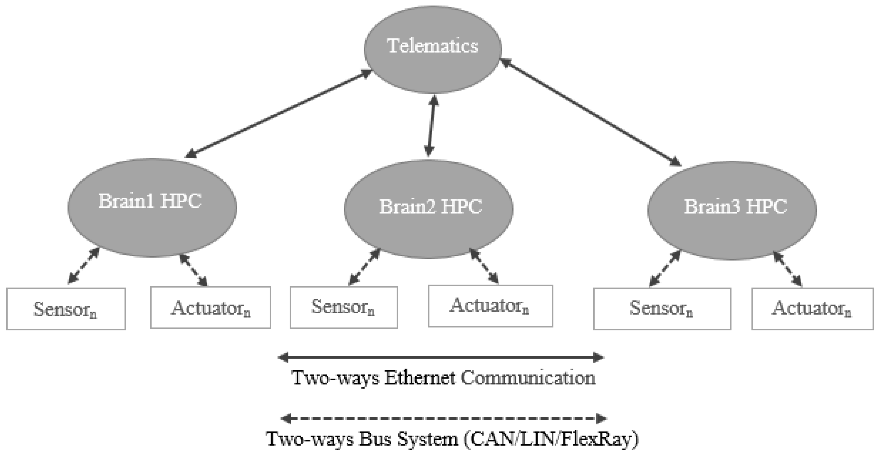
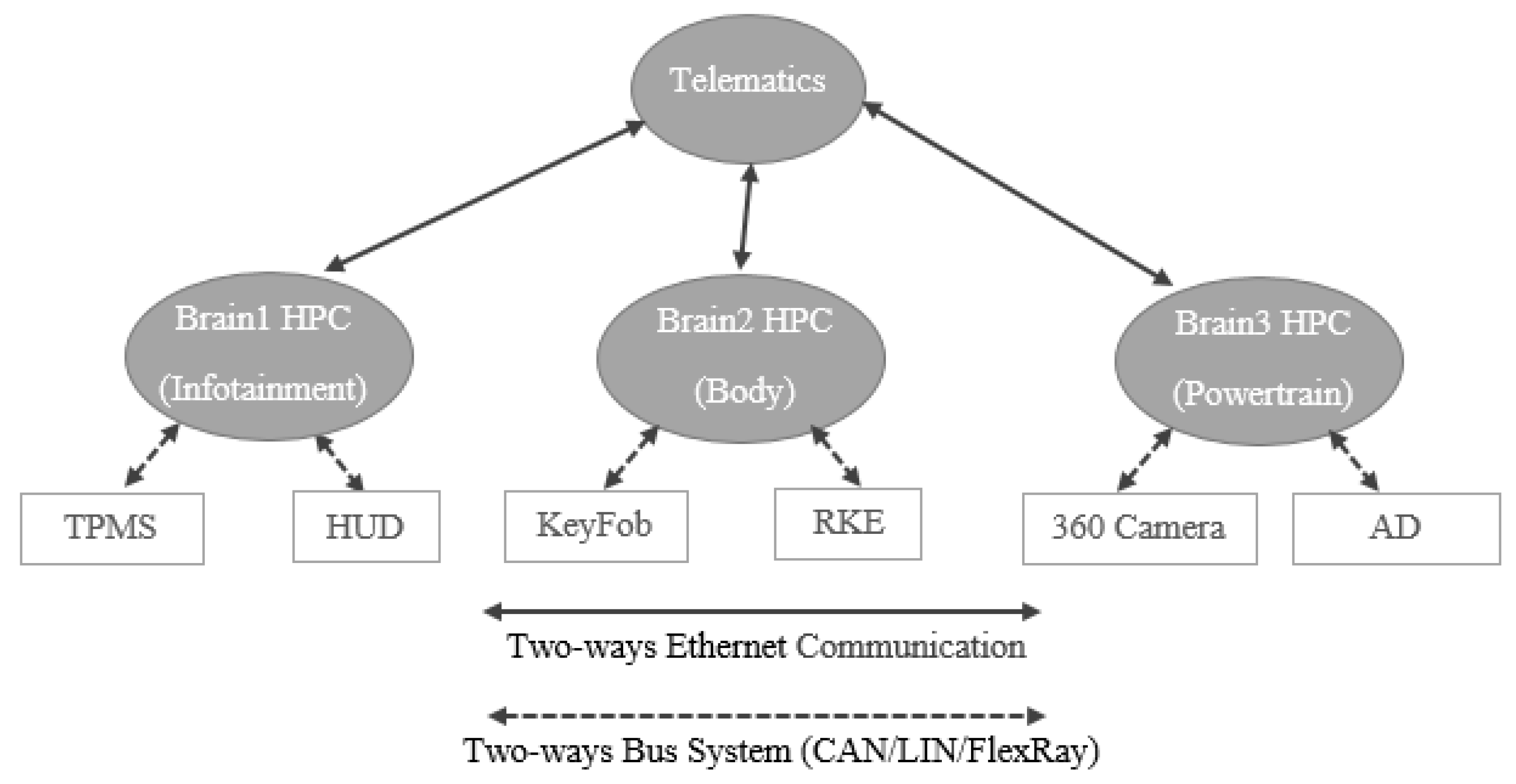
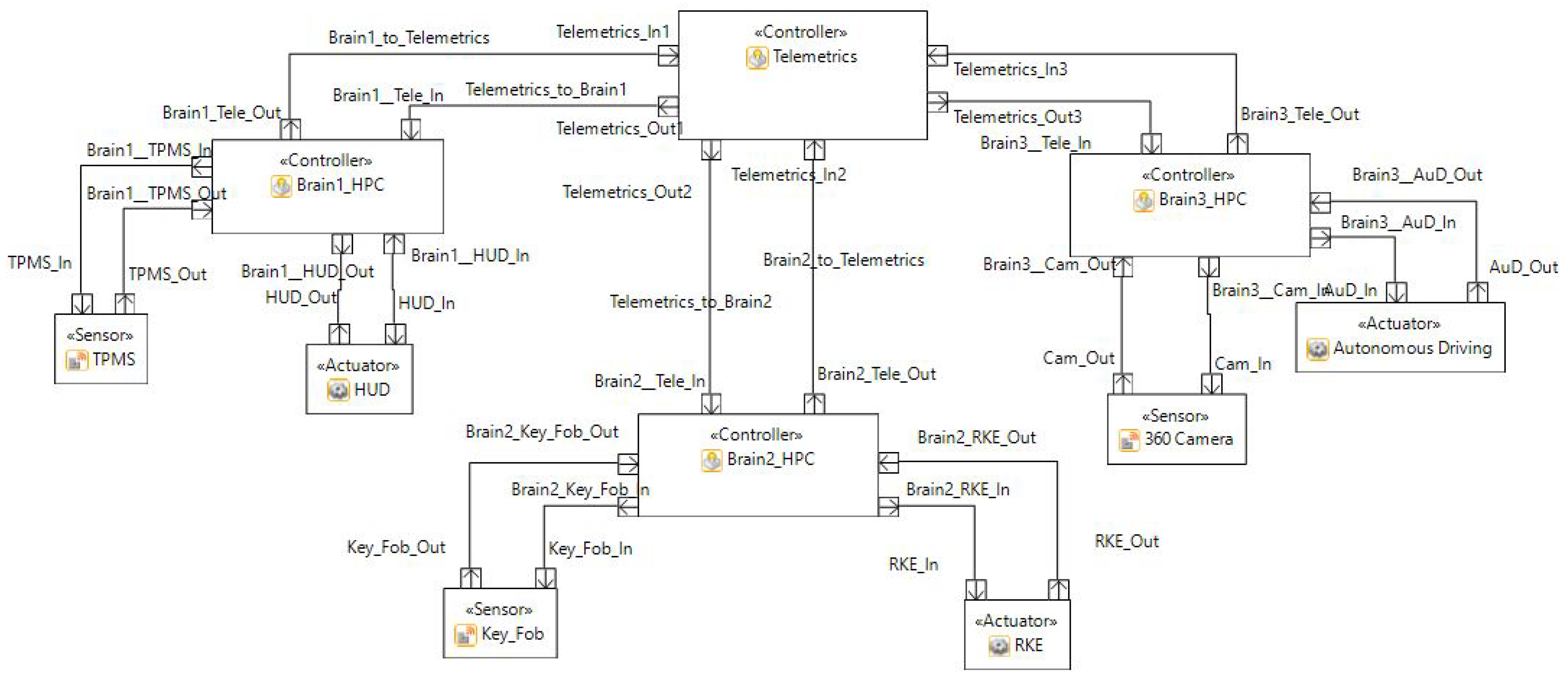
4.4. Three-Brain E/E Architecture

The three-brain architecture (see Figure 16) is the approach where modern vehicle functions (estimated at approximately 800) are distributed in three HPCs. Other names for this architecture are “three HPCs” and “Zonal Architecture”.
The architecture consists of three HPCs, where the functions of the vehicle are distributed in these HPCs in order to increase performance and reduce the overall load on each HPC. As shown in Figure 17, the three-brain architecture has three brains which are Brain1 HPC, Brain2 HPC, and Brain3 HPC. Each of these brains host several functions where the interators (sensors/actuators) are either directly connected to these brains or connected via ECUs (in this case, ECUs are responsible for managing the interactors), to be able to perform those functions. As with One-Brain and Two-Brain architectures, the communication between the Brain HPCs and the Telematics is accomplished using two-ways Ethernet channels and the communication between the Brain HPCs and the interactors (sensors/actuators) is performed using bus systems.
  • Use Case:
Assuming 800 functions are hosted by the whole vehicle, then approximately 266 functions are hosted on each HPC. The use case diagram of the three-brain architecture is shown in Figure 17, where only one function for each HPC (Domain) is illustrated. The three HPCs are assigned for three domains, such as Brain1 HPC is allocated for Infotainment domain, Brain2 HPC is allocated for Body domain, and Brain3 HPC is allocated for Powertrain domain in the use case diagram. Brain1 HPC receives the TPMS signal though a bus system, processes the signal, and sends the received value to the Head Unit Display (HUD). When the KeyFob is pressed or in close proximity, Brain2 HPC receives the signal from the KeyFob and checks whether the KeyFob is authentic and then opens/closes the door of the vehicle. Brain3 HPC receives the images taken by the 360 camera, recognizes the surrounding objects and drives the car autonomously based on the logic implemented in Brain3 HPC.
The distribution of the functions does not necessarily have to be even. The functions, which required high computational power, can be assigned to a brain with a higher processing power. In this case, autonomous driving (AD) can be connected to the brain with the highest processing power. Another way of distributing the functions can be based on the critical and safety function, such that these functions can be assigned to the brain with higher safety and redundant features. Figure 18 shows the realization of the three-brain architecture in the Ansys Medini Analyze software.
  • Advantages of the Three-Brain Architecture:
    • As three HPCs are networked together, this architecture will be better-performing than the one- and two-brain architectures.
    • Balancing the load is much easier with the division of the functions.
    • Able to ensure data integrity (the accuracy and consistency of data stored in a database) with redundant systems.
    • Easy to maintain and modify the HPCs in the architecture.
    • Scalable—each item can be scaled independently with higher memory and processing power.
  • Disadvantages of the Three-Brain Architecture:
    • Increased complexity in the network due to the interconnection of brains.
    • More communication nodes and cables due to additional HPCs.
    • Independent functionalities of the ECU can lead to the partial failure of functions.
    • An additional power requirement to power the additional HPCs.
    • Additional HPCs will lead to extra initial investment, which leads to overall vehicle costs. This implies higher short-term investments, which may conduct to a higher overall vehicle cost.
    • Hardware and software architecture is more complex than one-brain, two-brain and traditional architecture when heterogeneous hardware/software architectures are deployed.
    • Having three brains gives the attackers more attack surface than the one-brain and two-brain architecture.
    • Having redundant functions means keeping and running redundant codes which takes memory and CPU cycles.

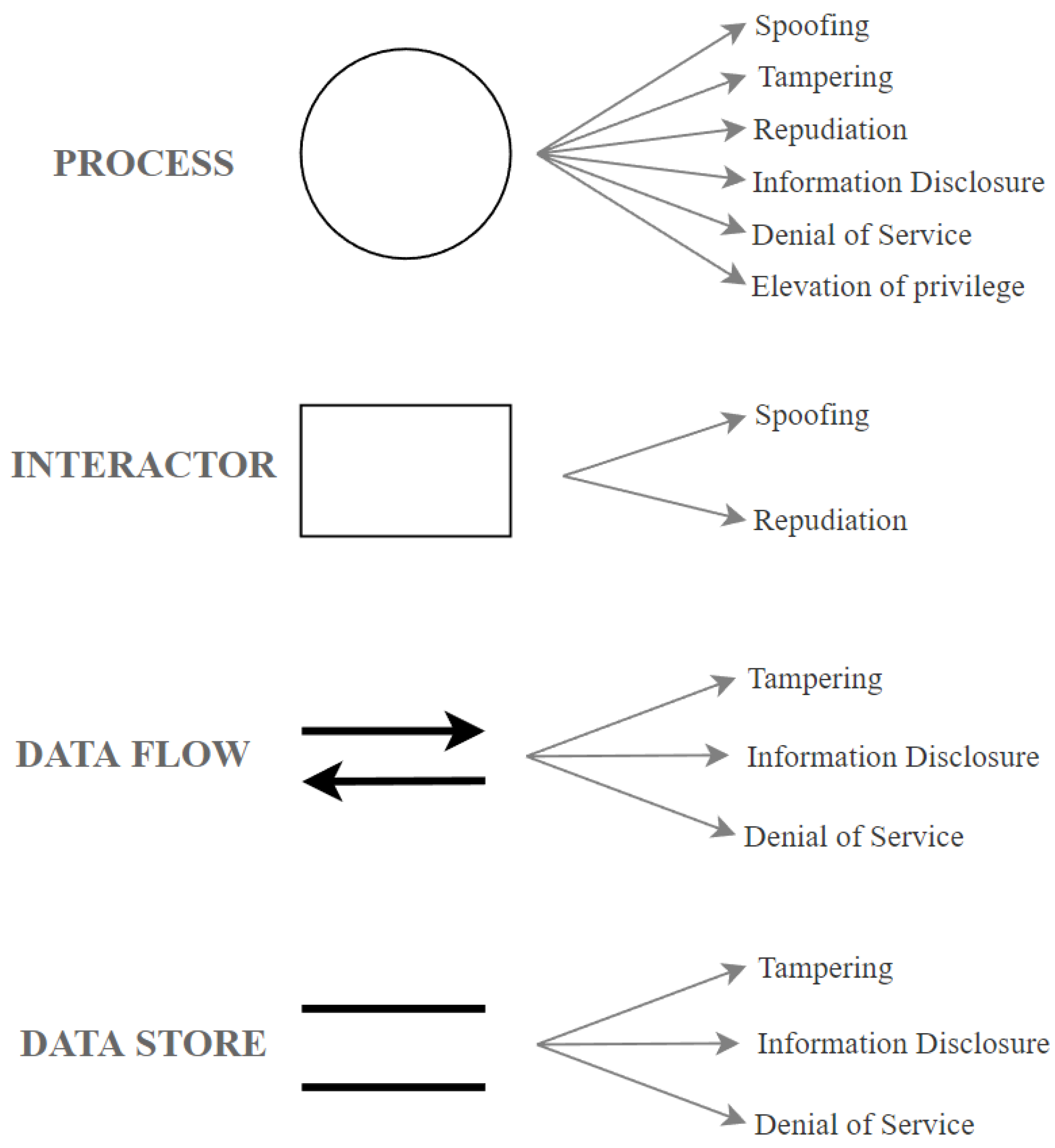
5. Security Analysis Using STRIDE

STRIDE is an acronym of six threat categories such as Spoofing, Tampering, Repudiation, Information disclosure, Denial of service, Elevation of privilege (STRIDE) and has been develped by Microsoft. When applied using a tool like Microsoft Threat Modeling or Medini Analyze, the method generates a certain number of threats for each component. Within the scope of the example architecture, the following components and corresponding number of threats can be defined:
  • Telematics Unit/ECU/HPC/Function = six threats, one threat for each threat category;
  • Sensor = two threats, one from spoofing and another from repudiation category;
  • Actuator = two threats, one from spoofing and another from repudiation category;
  • Connection port = three threats, one from tampering, another from information disclosure, and one from the denial of service category;
  • Data flow line = three threats, one from tampering, another from information disclosure, and one from the denial of service category;
Based on this information, an equation is created to calculate the total number of threats for the traditional, centralized, and zone E/E architectures. The variables used in the equation are explained as below:
T = T c p ( N t + N e + N b + N f ) + T c s a ( N s + N a ) + T c p d ( N p + N d + N d b )
where
  • T c p = number of threat category per process = 6;
  • T c s a = number of threat category per sensor or actuator = 2;
  • T c p d = number of threat category per port or data flow direction = 3;
  • N t = number of telematics unit, which is normally 1 in a vehicle;
  • N e = number of traditional ECU in the architecture which is 0 for the brain-based architectures;
  • N b = number of brains/HPCs;
  • N f = number of features/functions;
  • N s = number of sensors;
  • N a = number of actuators;
  • N p = number of ports;
  • N d = number of data flow lines;
  • N d b = number of databases = 0;
  • T = total number of threats.
In this equation, only one threat per threat category is considered. However, in practice, there are more than one threats per threat category.
A comparison of the number of threats in different architectures is given in Table 1, where an assumption is made to use 800 functions/features/apps in a vehicle, which are equally distributed in HPCs (one-brain, two-brain, three-brain architectures) or ECUs (traditional architecture).
In our studied traditional architecture, there is no telematics unit. The vehicle has 100 ECUs as each of the ECU hosts 8 functions. To realize 800 functions, 800 sensors and 800 actuators are required. Each sensor/actuator needs 4 ports to connect with a ECU (two ports on the sensor/actuator side and two ports on the ECU side) so the total number of ports are 800 times the sum of ports used for each sensor and actuator which comes out to be 6400. Similarly, 2 data flow lines are required for each senor/actuator. The total number of data flows is 800 times the sum of data flow lines used in each sensor and actuator which comes out to be 3200. In comparison to this, all other architectures are equipped with 1 telematics unit and each architecture has specific number of HPC (brains). One-Brain has 4 and 2 extra ports and data flow lines respectively in order to make connections with the telematics unit, which is further generalised such that for each added brain 4 extra ports and 2 data flow lines are required. Thus, in total 6404, 6408 and 6412 data ports and 3200, 3202 and 3206 data flow lines are required for One-Brain, Two-Brain and Three-Brain architectures respectively. In this calculation, databases are not considered but can be used as components in any other architectures.

6. Risk Analysis and Security Comparison of the Architectures

6.1. Security Threats and Damage Scenarios for Sensors

A sensor is a device that senses or measures the input from the environment and converts it into a digital or analog signal, which is readable by a controller (ECU/HPC). Then, the output is then displayed on a user interface, for example, Head Unit Display (HUD) or other displays located in the cockpit. Sensors have one or more threats in the categories of spoofing and repudiation.
  • Spoofing of sensor: The threat agent spoofs the identity of a sensor and sends malicious data to the ECU. Considering the example of TPMS, an attacker is able to spoof the tire pressure monitoring sensor and send the false data of the tire pressure to the display. This may result in a damage scenario such as the driver is panicked by seeing the very high/low tire pressure and goes to the workshop for it.
  • Repudiation of a sensor: The threat agent deletes or manipulates the data which are logged in the sensor and this results in the loss of data traceability, which is sent from the sensor to the ECU. This threat may lead to the operational damage of the vehicle, as the data stored in the TPMS (sensor) are manipulated or deleted by the attacker.

6.2. Security Threats and Damage Scenarios for Actuators

An actuator can be defined as the device which is responsible for taking an action such as producing the motion of a vehicle, based on a signal (accelerating, braking) received from a controller. Actuators are prone to spoofing and repudiation threats.
  • Spoofing of actuators: The threat agent spoofs the identity of actuators and sends malicious data to the ECU. Considering the example of the head up display (HUD), an attacker can spoof the HUD which may result in the improper functioning of the HUD. An HUD has important parameters to display, which guide the driver while driving, and the false information of these parameters may lead to fatal accidents.
  • Repudiation of actuators: The threat agent deletes or manipulates the data which are logged into actuators and this results in the loss of data traceability, which is sent from the actuator to the ECU. This threat may lead to the operational damage of the vehicle, as the stored data in the HUD (actuator) is manipulated or deleted by the attacker.

6.3. Security Threats and Damage Scenarios for Telematics Unit

As an ECU, the telematics unit is prone to threats in all six threat categories: spoofing, tampering, repudiation, elevation of privilege, information disclosure, and denial of service.
  • Spoofing of telematics: The threat agent spoofs the identity of telematics and sends malicious data to HUD or to any other interactor. This threat will mislead the owner of the vehicle, for example, by showing the wrong speed in the HUD.
  • Tampering of telematics: The threat agent tampers with the data of the telematics to manipulate the data or corrupt its operation.
  • Repudiation of telematics: The threat agent accesses the telematics unit and denies access to it afterwards. After accessing the system, attackers may change the configuration in the telematics unit which prevents the right users accessing the system. In addition, the attacker may try to access other functions and may modify the privileges to access the functions.
  • Information disclosure of telematics: The threat agent extracts sensible data/information from the telematics unit, such as Hardware/Software Configuration of the Device and sells the data to the competitors of the OEM/Supplier.
  • Denial of service (DoS) of telematics: The threat agent may cause the telematics to crash, halt, stop, or execute slowly by consuming or blocking resources, in all cases violating an availability metric. Attackers may try to flood the telematics with a huge number of requests, which results in the crashing of the system. Telematics may stop showing the data to the display unit.
  • Elevation of privilege of telematics: The threat agent executes telematics functions not available at the agent’s default privileges level. Attackers may try to access the functions which they are not authorized to use.

6.4. Security Threats and Damage Scenarios for Data Flows

  • Tampering the data flow: The threat agent tampers with the state/data of the data flow to manipulate the data during the transfer. The tampered sensor/actuation signal causes the loss of the integrity, which may cause life-threatening events, financial and operational damages.
  • Information disclosure: The threat agent intercepts the data flow and extracts sensitive data/information by tapping the signal. Then, the stolen data is used for the further misuse cases (e.g., stealing the key and unlocking the sequence from the KeyFob).
  • DoS: The threat agent floods or blocks the data flow, limiting its performance, throughput, or availability. An actuator can be made unavailable by damaging the signal wires or the network cables between the controller (HPC or ECU) and the actuator if the wires or cables are compromised. Thus, the actuator will not be available for the actuation. This may lead to life-threatening events, financial, and operational damage.

6.5. Security Threats and Damage Scenarios for HPCs

High Performance Computing (HPCs) consitutes the basis for the brain-based architectures. An HPC is an asset which comes under the process category and contains threats of all of the six threat categories: spoofing, tampering, repudiation, elevation of privilege information disclosure, and denial of service.
  • Spoofing of HPCs: The threat agent spoofs the identity of an HPC and sends malicious data to the interactors. This threat may result in fatal accidents, as the some of the actuators directly control the speed and acceleration of a vehicle.
  • Tampering of HPCs: The threat agent tampers with the process and/or data of the HPCs in order to manipulate the process and/or data and corrupt the functions to make the vehicle partially/fully non-functional.
  • Repudiation of HPCs: The threat agent makes use of an HPC and denies it’s access afterwards by deleting the access logs in the HPC. In case of an accident due to this malicious activity, it is not possible to detect the attacker.
  • Information disclosure of HPCs: The threat agent extracts sensible data/information from the HPC by accessing and reading its buffer/RAM/flash storage. Afterwards, the attacker might misuse the confidential information such as car logs, safety critical data, and device ID.
  • DoS of HPCs: The threat agent causes an HPC to crash, halt, stop, or execute slowly by consuming or blocking resources. In all cases, this means violating an availability metric. Attackers may try to flood the HPCs with a huge number of requests, which will increase the load to the HPCs and later, this results in crashing the system. HPCs may stop receiving data from sensors and sending data to actuators, which can cause a disruption to the vehicle operations. If this happens while on the road, this threat may lead to fatalities.
  • Elevation of privilege of HPCs: The threat agent executes HPC’s functions not available at the agent’s default privileges level. After accessing an HPC, attackers may try to access other functions for which they do not have access. The attackers may modify the privileges to access/close access to functions for them and for the other users.

7. Recommended Security Controls for the Architectures

To control the cybersecurity threats and risks, it is recommended to deploy a set of state-of-the-art security controls in the architecture. In the following, we proposed a set of security controls for the overall architecture, telematics unit, HPC, Ethernet, CAN/LIN/FlexRay, and sensor/actuator.

7.1. Security Controls for the Overall Architecture

  • Firewall: A firewall is a network security component which keeps track of the network devices/interfaces and filters requests based on its security policies. In vehicle communication, a lot of communications take place in in-vehicle and V2X scenarios. These communications are target for the attackers, therefore, in order to mitigate the risks, a firewall should be able to block illegitimate communication to an ECU or to the entire in-vehicle network.
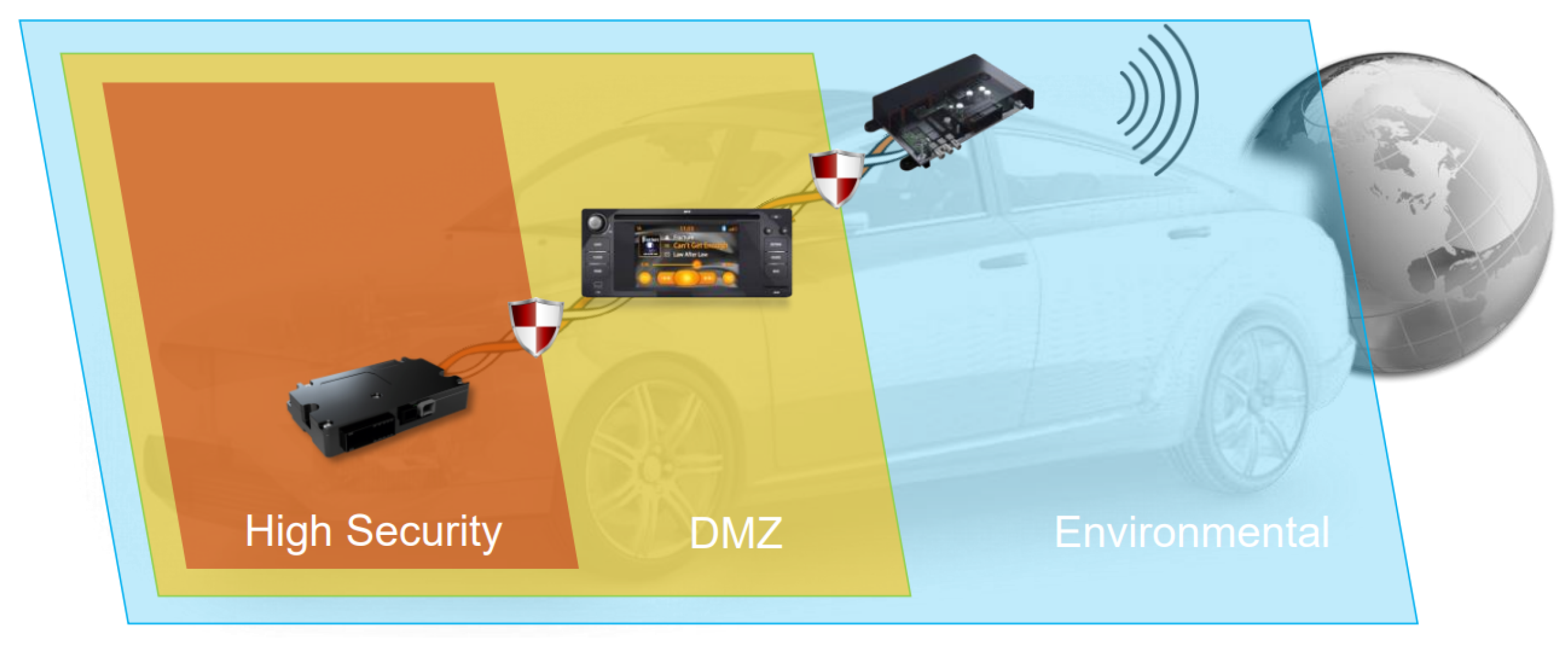
  • SEIS Zone Model: SEIS —“Sicherheit in Eingebetteten IP-basierten Systemen/Security for embedded IP-based systems” is a zone-based in-vehicle architecture considering cybersecurity risks [13]. There are three zones in the SEIS zone model, as shown in Figure 19. These are: the environmental zone, the demilitarized zone (DMZ), and the high secure zone.
The Environmental Zone: is an exposed zone of the vehicle, that connects the in-vehicle E/E architecture (telematics unit) with the outside environment, such as Road Side Units (RSUs). To be able to protect from the outside attackers, the telematic unit uses security controls such as firewalls (with many whitelisting IP/MAC addresses and domains), network-based anomaly detection, and access control for the diagnosis and other interfaces of the unit.
The Demilitarized Zone (DMZ): is located between the environmental zone and the high security zone and has medium security level and hosts infotainment or convenience functions. The components in this zone uses security mechanisms such as firewalls, host-based intrusion detection, network-based anomaly detection, and access control for debug and other interfaces.
The High Secure Zone: is a located inside the vehicle and is connected directly with the DMZ. This is the highest security zone within the vehicle and will contain all safety critical functions, such as ASIL C or D. Very few white list IP/MAC addresses are allowed to access this zone.
  • Identity & Access Management (IAM): The IAM refers to the processes that manage digital identities and user access to data, systems, and resources. IAM security includes the policies, programs, and technologies that restricts identity-related access. In order to mitigate risks related to authentication and authorization in an automotive system, an IAM must be implemented.
  • Intrusion Detection System (IDS)/Intrusion Prevention System (IPS): An IDS is used to detect an intrusion to an automotive system. There are IDS sensors inserted in different components within the in-vehicle which identify security incidents at the host and network levels. IDS sensors send data to the Intrusion Detection System Manager (IDSM), which filters the requests and generates qualified security events. Based on these events, security experts or Intrusion Prevention System (IPS) system located in the vehicle or in the cloud decide mitigation techniques. IDS uses pattern matching and machine learning techniques for the detection of the attacks.

7.2. Security Controls on Telematics

The main component in a vehicle to communicate with the other vehicles and RSUs is the telematic unit which contains many wireless interfaces, such as Bluetooth, WiFi and mobile communication interfaces including 2G, 3G, 4G, and 5G [14]. All of these interfaces need to be protected by deploying certain security controls. Some of these security controls are mentioned in the following section:
  • Bluetooth protection: One good example of how Bluetooth-enabled devices are kept safe from different types of attacks is through installing the latest version of the Bluetooth -driver and continuously updating the security patches.
  • WiFi protection: One good way of protecting the WiFi connection is by securing the network through strong passwords. This means that only those users possessing the password will have access to the network. To secure the WiFi, a series of security standards, such as the WiFi Protected Access (WPA) and WPA2 systems, have been introduced. The WPA2 uses the Advanced Encryption System (AES) and has been introduced in order to replace the more vulnerable Temporal Key Integrity Protocol (TKIP)-based WPA [15]. Furthermore, one of the most secure ways of preventing someone accessing a network is by using a virtual private network (VPN), as a method that may actually secure and encrypt certain types of communications. In addition, the vehicle and the legitimate devices should contain the latest version of the WiFi driver.
  • 2G protection: 2G is the second generation of mobile communications. It is an old technology created in 1991 that has many vulnerabilities along with the Signaling System 7—SS7. One of the most critical problems of the 2G was the weak encryption between the tower and the device. Therefore, hackers could easily attack the device intercepting calls and messages. Moreover, anyone may easily impersonate a real 2G tower. Security aspects of 2G are detailed in the Technical Specifications, TS 02.09 and 03.20, published by 3GPP. In addition, 3GPP published specification of GSM-MILENAGE algorithm (TS 55.205) and several other encryption algorithms (TS 55.216–55.218, TS 55.226, TS 55.919).
  • 3G protection: Mutual authentication is one of the priorities for 3G communication. Furthermore, the assurance regarding the authentication information and the keys that are not being re-used is required. Security architecture (TS 33.102), integration guidelines (TS 33.103), requirements for cryptographic algorithms (33.105), lawful inspection requirements and functions (TS 33.106–33.108), network domain security (TS 33.200, TS 33.310), Mobile Application Part - MAP application layer security (TS 33.210), security of multimedia broadcast/multicast services (TS TS 33.246), and other related cybersecurity related specifications are documented by 3GPP.
  • 4G/5G protection: Some of the technical security requirements and specifications of 2G/3G are also valid for the subsequent generations of mobile communication technologies including 4G and 5G. For example, the security architecture specification numbered as TS 33.102 is also valid for 4G and 5G.
  • DoS protection (rate-limiting): Denial of Service (DoS) attacks cause blocking of services and resources, so that the user cannot access and use these services/resources. This attack can be launched to the telematics unit as well. Attackers flood to the API endpoint of the telematics unit with a number of requests, so that legitimate users will not be able to use the services. This risk can be mitigated by using various filtering algorithms, such as upstream filtering and rate limiting. Rate limiting is the practice of restricting the number of requests to a service. This limit is defined by the service provider.

7.3. Security Controls on HPC/Brain Unit

  • Secure boot: A method to protect the HPC is to make sure that the device only uses software trusted by the OEM. Basically, the signatures of the firmware are checked against the signature stored in the secure area of a hardware security module (HSM) or in other secure storage. If the signatures match, the software is considered secure and the operating system is allowed to boot on the device. It uses a chain of trust to make sure the next file in the list for booting is legitimate and has not been tampered.
  • Secure debug: During debugging, using the On-Board Diagnostics (OBD) or Diagnostic Trouble Code (DTC), the system of the vehicle is checked for the software/hardware problems. The diagnostic performed while the vehicle is running should be stored securely using encryption and/or signature mechanisms. These diagnostic messages are mainly related to emissions. On the other hand, when diagnostics are performed in a workshop, all the ECUs are checked and the focus is on other aspects including functionality and reprogramming.
  • Secure logging: Logs stored in the secondary storage (SSD) are used for many helpful intentions, such as intrusion and anomaly detection. They contain sensitive data such as privacy related info. Therefore, it becomes necessary to secure the logs. This can be achieved by using encryption mechanisms to store the log data after the encryption and limit the access to the logs for the right users/workshops. The users/workshops should be authenticated and authorized before accessing the logs.
  • Secure storage: HPC should deploy one or more Hardware Security Modules, in short HSM [16], to store, generate, and protect cryptographic keys. In addition, such a module is able to fulfill the safety and timing requirements of a service (for example, airbag) due to its higher performance compared to the software implementation of executing a cryptographic function.
  • Core pinning: Different security/security critical functions should run in separate area within the HPC. One way to separate it using so called core pinning, where each core of the micro-processors has its own vertical software stacks. Assuming that, a processor with 16 cores will have 16 separate operating systems, middlewares, and applications. Having each OS has its own computing and memory resources enables higher separation of resources.
  • OS separation (virtualization): The next level of separation is achieved using virtualization techniques, where both bare metal hypervisor (when higher performance is required) or hosted hypervisor can be deployed. Bare metal hypervisor, such as VmWare, ESX, Hyper-V, and Xen contains device drivers which are able to run several operating systems by giving them own memory and computing resources. Hosted hypervisor such as VmWare Workstation, VirtualBox, does not contain device drivers, and are run on top of the host operating systems. The hypervisor is then able to host several guest operating systems by allocated them memory and computing resources.
  • Application/process separation (containerization, docker): Containerization is the process of creating a single executable package of the software (including application code, libraries, and dependencies) of providing one or more vehicle functions. Contrary to the virtualization using VMs, the containerization process does not include a copy of the OS in the package, instead, it installs the run-time engine on the host OS. The docker is the platform that may be used for the containerization process.

7.4. Security Controls for the Ethernet

  • MACSec: MACsec is commonly used in IT network, however, it is one of the new security controls for in-vehicle communication. One of the characteristics of the MACsec is that it protects data communication in the lower level (Ethernet) of the protocol stack. However, MACsec alone cannot ensure end-to-end security. Several reasons against deploying MACsec for the in-vehicle communication are higher cost, performance degradation, and very few providers offer MACsec features in their SoC (System on Chip).
  • IPSec: It is an approach to secure data communication which uses IP protocols and is able to offer end-to-end (IP-to-IP) security. IPSec was originally designed for IPv6, but it is also used for IPv4. Some relevant references of IPSec are RFC3686, RFC4302, RFC4303, and RFC5996. IPSec is able to ensure authenticity, confidentiality, integrity of the messages between two ECUs having unique IP addresses. Virtual Private Network (VPN) uses IPSec protocols.
  • Transport Layer Security (TLS): It is the successor of the secure socket layer (SSL) and this protocol is supported by the AUTOSAR architecture. TLS supports application-to-application (Port-to-Port) security. TLS is able to ensure authenticity, confidentiality, integrity of the messages between two applications running on two ECUs having unique port numbers. It is recommended to use the latest version of TLS protocol which is version 3 in 2022.
  • Virtual Local Area Network (VLAN): It allows to create multiple logical networks in the in-vehicle architecture to separate one network from another, thereby, the service provider such as OEM and Tier1/Tier2 supplier is able to implement individual security policies in each of those networks.

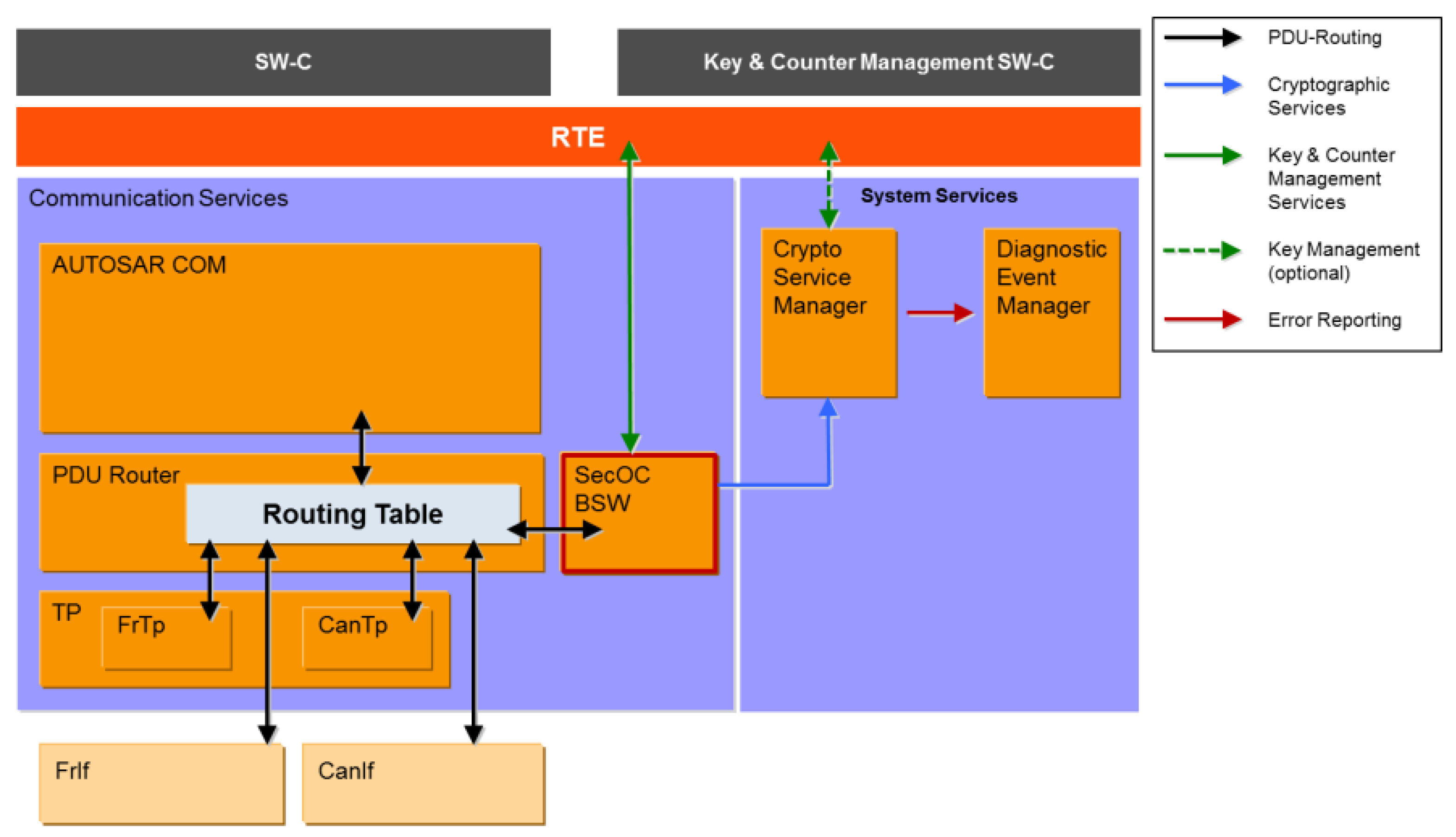
7.5. Security Controls for CAN/LIN/FlexRay

  • Secure Onboard Communication (SecOC): To protect the in-vehicle communication that utilizes bus systems (CAN/LIN/FlexRay), AutoSAR [17] introduced the concept of SecOC (see Figure 20), which is used to validate the authenticity of the single transmitted protocol data unit. It also helps detecting attacks such as replay, spoofing, and tampering.

7.6. Security Controls on Sensors and Actuators

  • Authentication: Sensors and actuators should be authenticated before initiating the communication to protect from spoofing threat categories.
  • Logging: The logging information of the sensors and actuators should be encrypted and kept in a secure memory storage, and given only the legitimate users the access to the data.

8. Related Work

Autonomous vehicles are the next step in the evolution of the automotive industry. According to the Taxonomy and Definitions for Terms Related to Driving Automation Systems for On-Road Motor Vehicles J3016_202104 committee [18], there are six levels of automation for autonomous vehicles.
  • Level 0: No automation;
  • Level 1: Driver assistance;
  • Level 2: Partial automation;
  • Level 3: Conditional automation;
  • Level 4: High automation;
  • Level 5: Full automation.
The advanced electrical systems in a vehicle require constant communication within on-board components and the cloud to ensure the proper functionality and security of the vehicle. This necessity of uninterrupted communication has made the security of vehicle systems vulnerable to malicious attacks from hackers. There have been several incidents where the hackers were able to take partial control over the vehicle’s autonomous functionalities. The infamous Jeep hack in 2015 [19] incident shook the autonomous cybersecurity community in terms of the control, safety, and security of such vehicles. In order to stay on the same page worldwide, in terms of automotive cybersecurity, the industry experts collaborated and created a standardized version for all automotive manufacturers to follow. The International Organization for Standardization (ISO) in collaboration with SAE International took the recommendations gathered in SAE/J3061, the Cybersecurity guidebook for cyber-physical vehicle systems and developed the most recent ISO/SAE 21434 [11] Standard for Road Vehicles—Cybersecurity Engineering.
For existing peer-reviewed scientific work from the research community, the authors of this paper performed an in-depth search in scholarly data repositories. The following keywords were used to explore the existing work on this topic:
  • Cybersecurity automotive E/E architecture (CSAEEA);
  • Motivation hacking E/E architecture (MHEEA);
  • Autonomous vehicle SAE level (AVSAEL);
  • Cybersecurity related to distributed architecture (CSRDA);
  • E/E architecture for automotive security (EEAAS).
Scopus, Web of Science, IEEE, Science Direct, and Google Scholar were explored for this purpose. Table 2 represents the data for this research.
The authors of the paper [20] provided the security analysis of autonomous vehicle including the threat and risk analysis using STRIDE and CVSS. The authors also suggest a set of security mechanisms for the topmost threats.
Philip Koopman and Michael Wagner explored in their work the existing safety concerns regarding autonomous vehicles [21]. As the manufacturing of autonomous vehicles is a highly inter-disciplinary domain, there is no one way of diagnosing and mitigating the threats and risks concerning the passenger and bystander safety. Their work presents a few generalized safety concerns which are worthy of attention to be resolved in a coordinated, cross-domain manner. They are open to the possibilities of having more high-risk problem scenarios that they have not covered or might emerge in the future. The main focus is to create awareness in terms of existing automotive security concerns.
According to the autonomous vehicle researchers of [22], under certain conditions, the passengers could not tell the difference between a human and an AI driver. They performed a study with a level 2 autonomous vehicle. The passengers could not see the driver and they were asked to distinguish between the manual or AI driving performance. This study was mostly focused on the humanness of the autonomous functions. The authors used a Turing algorithm-based model to verify their hypothesis among their subjects.
The authors of [23] explored the lane-level maneuvers to provide oversight to guarantee safety for the autonomous vehicles on the road with a survey. The modern Global Navigation Satellite Systems (GNSS) and their increased level of accuracy are facilitating the detection of road at the lane level. This is a revolution in terms of making the autonomous vehicles to advance into level 3 and level 4 of SAE standards. With increased accuracy, the autonomous driving functions are able to perform better, using more precise data from the GNSS satellites.
Cyber-attacks on cyber-physical systems are currently not a surprise. The attackers are constantly trying to find new ways to break the security protocols of cyber-physical systems in order to reach the “Flow state”. According to the flow theory from [24], the motivation behind hacking can be described from a psychological perspective. Different researchers have attempted to classify the motivation behind hacking over the years. In [25], the author proposed a conceptual model of hacker development and motivation. In this work, the author presents a conceptual model on the basis of five different motivational prospect: flow, control, attention focus, curiosity, and intrinsic interest. From this paper, it is evident that there is no singular reason for hacking. Hackers have varied motivation behind their actions. The reasons vary from remuneration, revenge, control, curiosity, to sense of belonging to the hacker community, in addition to many other reasons. It is difficult to pinpoint just one particular reason, as people are motivated by different factors. In automotives, the motivation for unethical hacking is mainly focused on the remuneration or financial benefits against the investment and the risks involved in the act of stealing smart vehicles. The financial prospect is the single most motivating factor for such an act.
In [26], an investigation regarding security breach detection methods for automotive E/E architectures was performed. To that end, the researchers suggest in-vehicle network traffic monitoring to find altered message streams which are transmitted at higher rates. Attacks that cause timing errors can seriously impact safety-critical operations. There are methods in place, those which can perform the automatic detection of breaching messages within the scope of a chosen E/E architectural component. They work on a subset of ECU and enable cost reduction and prevent single points of failure. In order to identify the communication characteristics and properties required for identifying security assaults, they first evaluated a specific E/E system architecture. The distribution of attack detection jobs and parameterization of the appropriate detection algorithms were then carried out. To provide the complete coverage of the E/E system architecture and prompt attack detection, the authors employed a lightweight message monitoring technique and strategically arranged detection duties.
Automated driving necessitates greater vehicle networking, which expands the attack surface of the vehicles. In [27], the authors discussed a number of security design patterns that aimed to target and minimize the consequences of key steps in automobile attack chains. These patterns provide a method of transmitting security-related events within a vehicle network and reporting them to units outside of the vehicle, enabling the detection of anomalies in the firmware when booting, detecting anomalies in the communication in the vehicle, blocking unauthorized control units from successfully transmitting messages, and ensuring that communication in the vehicle is secure. The researchers also show how these security design patterns can be leveraged to become aware of the current attack environment using the example of a future high-level E/E architecture.
In the near future, rules will outline standards for cybersecurity at various levels in the automotive industry. A cybersecurity management system (CSMS) that addresses the entire vehicle lifespan and ecosystem is necessary at an organizational level. Additionally, An OEM having a vehicle for a type approval must perform tasks according to the ISO/SAE 21434 standard [28].
In the work of Mundhenk et al. [29], a new approach to the security analysis was proposed. The authors described the probabilistic model for the security analysis at the system level. This work highlights the security issues that need to be addressed.
The paper on service-oriented architectures [30] describes the potential security measures and outlines the specific security features. The signal-oriented measure will be replaced by the service-oriented architectures, as the necessity of upgrades and updates becomes more evident. The authors proposed a hybrid architecture as a countermeasure for security breaches.
In [31], the authors presented potential software and hardware threats in architecture designs and outlined upcoming security challenges. Highly heterogeneous state-of-the-art architectures and complex systems in autonomous vehicles are relying more on distributed software and hardware systems. The authors analyzed the architecture for automotive design, based on Ethernet/IP communication stack and provided possible verification using formal methods.
The authors in [32] have presented the fundamental aspects of cybersecurity in the automotive domain such as threat and attack scenarios, and countermeasures. The major focus is pointed on the in-vehicle network, including its requirements, protocols, and their vulnerabilities.
The testing and evaluation of automotive cybersecurity systems lack proper testing methods, content, standard, tools, and other prospects. The paper [33] gives an overview on cybersecurity testing and proposes a unified evaluation method. It carries out a threat analysis and suggests 108 tests.
As compared to the pace of development in cybersecurity systems, it has become strictly necessary to improve the validation and verification of systems according to the standards during the manufacturing process of vehicles. A solution for cybersecurity testing in the automotive is described by the authors of the article [34]. This paper outlines a structured testing process for verifying and validating the automotive cybersecurity. The method proposed here attempts to create a combined approach between manual and automated testing methods and practices for cybersecurity standards. The process described in this framework also allows the implementation of individual tool-sets according to needs.
The authors of the article [35] highlighted the importance of authentication and proposed a system that is more user-friendly using single sign-on and so, they eliminated trusted third-party dependency to avoid data breaches.
The researchers of [36] investigated whether the TLS protocol is applicable to secure in-vehicle networks and how TLS is able to fulfill the performance requirements of the automotive industry.
In [37], three use cases for which TARA is performed are presented and the results are discussed.
The authors of the article [38] proposed a multi-layer defense concept, which represents the basis for the development of further security mechanisms.
In [39], the authors considered a smart architecture against the common cyber-attacks (malware, buffer overflow) with redundant ECUs and dedicated memory allocation.
The authors of [40] discussed the configuration for a centralized architecture and the cybersecurity impacts and measures that needs to be considered for the implementation. The real-time references were considered by comparing the architectures of on-road vehicles by different OEMs.
In [41], the authors presented the cybersecurity in the CAN communication protocol in the vehicle communication and four different methodologies are being considered.
The paper [42] describes the E/E architectures, including functional, logical, and technical aspects.
The authors of the paper [43] give the direction in which the automotive industry is moving forward and the importance of IT in a modern automobile.
The work of Dominik, Udo, Michael, and Matthias [44] presented the transition from the old to the new architecture and mentioned some advantages of an HPC-based architecture, while our paper described and compared in greater detail some of the available options of new in-vehicle E/E architectures.
Sergi, Leonidas, Carles, and Jaume proposed in [45] a way to make the HPC-based architectures more fail-safe, as compared to our work, in which we document various weaknesses and strong points of these architectures without proposing additional changes.
In [46], the authors focused on the incident/attack detection of a CAN bus architecture using machine learning (ML) algorithms, support vector machines (SVM), and logistic regression. Compared to our work, we have additionally mentioned cybersecurity threats and damage scenarios of the entire system and not only CAN bus.
The security assessment of ECU by the CyberSecurity Evaluation Framework (CSEF) is mentioned in [47]. It has the same analysis criterion as TARA, but rather than using the tool Medini Analyze, the authors used their own methodology.
From the exploratory approach towards the existing research, it is evident that the literature does not only focus on the technological aspect of this research topic. The research community is primarily focused on improving the technology. Other than that, the identification of the areas with higher vulnerability and threat is also highly sought after. The community is working towards the mitigation of the vulnerabilities by identifying, analyzing, and resolving existing problems. There are several high-end software and tools that are helping in it. Testing in terms of the validation and verification of CSMS procedures is also being worked on. This area has a lot of potential for structured development and standardization. As autonomous vehicle development is a multi-disciplinary domain of work, only the improvement of the software, hardware, or network security would not ensure an optimum outcome. Other than the technical aspect of the topic, some researchers are investigating the psychology of hackers. This helps understand the motivation behind hacking and it also helps in the development of intervention methods for potential attacks. In order to achieve the highest possible performance and the efficiency of the systems while ensuring security standards, all of the components in the lifecycle of the development have to work hand in hand.
From the observations of the existing literature, the authors of this paper have observed that the related works lack a comparative study of the existing E/E automotive architectures. This work helps enrich the existing literature to tackle this shortcoming for existing and future E/E architectures. In this paper, the authors provided a comparative image of four different automotive E/E architectures and their benefits and drawbacks. Based on this work, future researchers will have a better outlook on architectures, while further pursuing their work.

9. Results

This article evaluated different architectures in the automotive sphere. Firstly, the qualitative comparison was discussed, which suggests that two-brain and three-brain architectures provide the possibility of better scalability and redundancy as compared to the traditional and one-brain architectures. It is an important parameter for next-generation automotive cybersecurity research. Obviously, the cost will be higher as the number of HPCs increases, but the performance will also be higher. The HPC also provides flexibility for memory management and software updates using over-the-air-update. Secondly, during the quantitative analysis for the number of threats associated with the architecture, it has been observed that the traditional architecture poses a greater number of threats because it has a greater number of processes (each process contributes to six threats) and ports. On the other hand, a one-brain architecture shows the least number of threats compared to all the other discussed architectures. However, the two-brain and three-brain architectures show various other advantages such as load-balancing and performance.
In the following, a comparative analysis of the architectures is presented for a better overview of the conducted research.

Comparison of Automotive E/E Architectures

Table 3 presents a comparison between the four E/E architectures in terms of various attributes, that will be detailed in the following.
  • Architecture: In the traditional architecture, the ECUs are located in different areas of the vehicle, and these ECUs (fully/partially) are able to communicate via a communication network to achieve a specific objective or goal. Thus, the architecture is distributed. In a one-brain architecture, there is only one brain that has control over the entire network and components connected to it. Thus, the one-brain architecture is centralized. Zone architecture means that depending on how many HPCs we have and their location, there can be two zones, as in the two-brain architecture, or three zones, as in the three-brain architecture. However, a zone-based architecture offers the advantage of having control of the vehicle functions on specific zones. To do this task, sometimes additional ECUs are connected to the brain architectures between the HPCs and the sensors/actuators.
  • Performance: The term performance is defined as the qualitative level of a critical property at any considered point in time [11]. Therefore, in the vehicle architecture performance is one of the most important parameters, and can be measured in terms of cache size, memory size, and processing power. The performance in a traditional architecture is low, since it possesses low performance ECUs to host very few functions. The performance of a one-brain architecture is more than traditional architecture as it has one HPC and is able to host more functions than the traditional architecture with many ECUs. The performance of a vehicle with two-brain architecture is more than a vehicle with one HPC. The performance of a vehicle with three-brain architecture is more than the performance of a vehicle with two-brain architectures. By adding more HPCs, it is possible to increase the performance of a vehicle.
  • Cost: The cost considered here is the expenditure required to realize a vehicle architecture. The cost to implement the traditional architecture is low because the ECUs are not expensive as compared to HPCs. Even though one hundred ECUs are used, the overall cost will be lower when compared to a single HPC. In a one-brain architecture, the cost is medium, since it has only one HPC. Similarly, in the two-brain system and three-brain system, the cost is high and higher, since these architectures have two HPCs and three HPCs, respectively. The functions are hosted accordingly to each HPC and the cost of the vehicle increases when it has more HPCs and more functions.
  • Wiring complexity: The wiring complexity is very high in a traditional system, since it does not have HPCs. The traditional system has numerous ECUs and each ECU needs a set of wires to interface the different sensors and actuators connected to it. In a one-brain architecture, the wiring complexity is low, since there is only one brain and centralized wiring requires less interconnections. In a two-brain architecture, the complexity increases to medium, as compared to one-brain because of the two brains (two zones). Similarly, in the three-brain system, the complexity for the connection of wires is high as compared to the other architectures. To conclude, the complexity is the highest in the traditional architecture.
  • Scalability: Scalability is defined as the setting of the scope of capabilities of a system, as determined by its functionality [11]. In the traditional architecture, ECUs are limited to a set of functions and therefore, the scalability is very limited. Coming to one-brain architecture, since all the functions are already assigned to a single HPC, there is no scalability. In two-brain and three-brain architectures, there is a possibility of scaling, since these architectures have multiple HCPs and each HPC will still have sufficient computational power to compensate the added functionalities.
  • Redundancy: Redundancy is one of the most critical parameters which is required in the case of a particular system failure. In the traditional architecture, the possibility of having redundancy for safety critical features is possible, but it is very low. The redundancy is possible in the traditional architecture using redundant ECUs to host the same function. The redundancy, however, cannot be implemented using core pinning or virtualization techniques which are possible in the HPC-based architectures. In a one-brain architecture, since there is only one brain, in the case of the failure of that brain, there is no possibility of redundancy unless a second brain is introduced. When vertical software stacks are implemented on top of processor-cores and core pinning, redundant functions can be hosted on top of multiple cores. Implementing virtualization techniques, redundancy can also be realized on a HPC. Since two-brain and three-brain architectures have more memory and computing resources, it is possible to implement the redundancy mechanisms. Human lives are of the utmost importance and being able to make sure that the systems in a vehicle are more fail safe due to additional functions that could save a life.
  • Load-balancing: Load-balancing means that the system is able to balance the workload and share it among processes. The traditional architecture is not made for load balancing. However, it is possible to implement mechanisms to do this. The load-balancing of different cores in the SoC of a one-brain (HPC) can be implemented. However, load-balancing is easier to implement by decoupled hardware devices such as two-brain and three-brain architectures.
  • Vulnerability: The topic of vulnerability is a widely-discussed one, as it plays a major role in determining the risk levels of an asset/component. Vulnerability includes the weakness of an asset or group of assets which can be exploited by a threat of an attacker [11]. Threats will always exist, but by managing the level of vulnerability, greater levels of security can be ensured and the probability of an attack drops significantly. In this field, the traditional architecture shines, as if even one ECU gets hacked, the design ensures that the others are safe. On the other hand, this architecture imposes severe limitations on other fields, so we need to reach a compromise. Adding HPCs in the design increases the grade of vulnerability, because if the brain is hacked, the vehicle may be prone to an accident. With three brains, we have a higher level of vulnerability. However, by deploying appropriate security controls such as IDS/IPS/firewall, the attacks can be minimized even though there are vulnerabilities in the system/architecture.
  • Troubleshooting: Vehicles are made to be driven; systems are made to be used and eventually parts are bound to become worn out or damaged. Furthermore, sometimes these damages are not easy to diagnose in complex vehicle architectures. When speaking about the criteria for troubleshooting a vehicle, we are referring to the efforts needed to detect a problem. Troubleshooting in a traditional architecture takes the most effort since it has higher complexity and many ECUs. The troubleshooting process can be considerably shortened by introducing HPCs in the architecture. Although the number of efforts increases with every brain added, overall traditional architectures have the most effort required for troubleshooting.
  • Repairability: Repairability measures the efforts needed to repair a component or asset in an architecture. Repairing the ECU of a vehicle can be a tedious process, especially when dealing with the traditional architecture, because of its wiring complexity and distributed architecture which have hundred of ECUs. By introducing the one-brain architecture, the difficulty of the process drops significantly and steadily increases with every extra HPC that is added.
  • Memory management: It is a method for coordinating and controlling the computer’s main memory. Thus, in the case of the traditional architecture, memory management is not an important topic as the ECU has very few functions (typically, one or two functions). However, in the other three architectures, memory management is a must, so HPCs are needed to properly manage the space and the allocation of files, so that the operating system, applications, and other running processes have enough memory to perform the operations.
  • Weight: The weight of a vehicle is a key parameter when talking about speed, acceleration, environmental liability, or fuel consumption. In the current state, wires, cables, and other parts needed for the traditional architecture make the vehicles heavier than they should be. Switching to an HPCs-based architecture could lower the weight and thus improve other parameters such as those mentioned above. However, with each additional HPC comes more weight added to the vehicle.
  • Software update: In the traditional architecture, with few exceptions, the software update is done manually. This means that the user has to take the vehicle to the OEM/distributor and the update is done by connecting the vehicle physically. In one-, two-, and three-brain architectures, the software update can be automated using over-the-air (OTA) update, whenever there is new software/update available.
Equation (1) is generic to all architectures. The number of threats can be easily determined for any number of brains (HPCs), ECUs, sensors, and actuators. This helps the readers of this article to produce their own system design-based threat scenario.

10. Limitations and Future Scope

This paper is mainly focused on providing the generic functional and security comparison between the architectures. It considered the fundamentally constructed use cases for the four architecture types and analyzed the threat and damage scenarios associated with them, according to the ISO/SAE 21434 standard. The scope of this work is primarily focused on producing a comparative outlook for the readers using qualitative criteria. The limitation is that the authors do not provide the quantitative data of the parameters in detail for the comparative components between the architectures. Each of these components can be further explored in detail for quantitative perspectives and analyzed to create an in-depth knowledge. In the following section, the authors proposed some ways to improve the studied architectures.
  • Traditional Architecture
Method 1: Wireless communication between ECUs and interactors (see Figure 21)
Implementing wireless communication in the traditional architecture will reduce the wiring complexity in the car. ECUs and interactors with wireless or cellular network compatibility are able to communicate with each other without cables. This will also reduce the physical threats (for example, cutting the cables, plugged in/out, etc.) associated with the cables and their connecting ports.
Method 2: High-power ECUs (see Figure 22)
The use of high computing power and memory size (called, high-power) ECUs is able to host many functions (more than eight). However, there might be an increase in cost, as the high-power ECUs are expensive, but this will reduce the number of ECUs required in the car, which in turn, may reduce the number of threats in the whole car.
  • One-Brain Architecture
Method 1: One brain architecture can be improved by adding a second communication channel between the telematics unit and the HPC. This redundant communication channel helps the vehicle running in case of the failure/DoS attack to the original channel.
Method 2: Another way to improve the one brain architecture is to utilize a SoC with many cores, so that, performance, safety, security, and non-safety functions are able to run in separate security zones. As mentioned earlier, mechanisms such as core pinning, bare metal virtualization, hosted virtualization, and containerization are able to realize the separation along with implementing the strict access control.
  • Two-Brain Architecture
Method 1: The two-brain architecture may be improved by adding a load-balancer between the HPCs and the interactors (actuators and sensors), distributing the load among the two HPCs. Additionally, in the same scenario, a shared RAM memory and/or data store between the two HPCs would improve the efficiency and performance. Shared memory can help the processors to load the programs faster for computation. However, adding additional component in the architecture will increase cybersecurity threats and risks.
Method 2: The architecture can also be improved by interlinking two HPCs using an Ethernet cable, so that they can communicate directly without the help of a switch/router and will increase performance for the communication. However, in this case, when the attacker gets access to one HPC, then he will be able to access the other HPC if no security control is placed in between the HPCs.
  • Three-Brain Architecture
Method 1: Similar to the two-brain architecture, this architecture can also be improved by the interconnection of the three HPCs as a mesh network or by adding a load-balance in between the telematics unit and the HPCs. This improvement will open doors to parallel and cluster computing, which will also help balance the load for complex computations, such as ADAS and the use of other AI and ML-based functions. Furthermore, this will be helpful for system redundancy; in the case of a failure of one HPC, the load can be redirected to the other brain. However, this will only be possible if all the sensors and actuators are interfaced with the HPCs via a router or gateway.
Method 2: A three-brain architecture may be improved by optimizing cost and power. With the advancement in technology and chip manufacturing in the future, HPCs will be more cost-effective and power efficient and this will improve the three-brain architecture in terms of cost and power. Furthermore, this will help implement architectures with three or more brains in mid-range and high-range cars.

11. Conclusions

As shown above, there are several approaches when scrutinizing the architecture of a device or a car and each one has its strong points and its drawbacks. While this paper documents and specifies four different engineering solutions, engineers might have to deal with more complicated options as time passes and technology advances. When discussing about the traditional architecture, long and complicated wiring, or difficult-to-program ECUs are some issues. However, it also presents low vulnerability levels due to strict and safety programming environment and standard like AutoSAR Classic, while keeping the costs down, making it the ideal approach for some components and cars.
With the introduction of HPC-based architectures, it is observed that brain-based systems more efficiently manage the data processing, storage and cables, which considerably reduce the repair and troubleshooting effort, while reducing the overall weight of the car. Despite that, in the case of an attack, the one-brain architecture has no redundant HPCs available and also no way to extend the scalability, due to its centralized system design. It is often used in TPMS or remote keyless systems (for example, Remote Keyless Entry Systems—RKE, Passive Entry Passive Start—PEPS). By adding another HPC, we reach a middle ground in this new architecture that strikes a good balance, by not falling into any extremes. The perk of load-balancing combined with the redundancy coming from the second HPC creates a harmony. With the negative side of increased weight and the effort needed to repair this zone-based architecture, it works best in cars that fall into the high-end tier, while keeping costs in mind. Going up another level, we reach a three-brain architecture, which also presents its shortcomings by being more vulnerable, costly, and open to many more threats than the previous entrances in the list. Again, this architecture is equipped with massive computational power backed by great efficiency, which is further enhanced by the workload distribution among the three HPCs. As expected, this architecture truly outshines the others, as the state-of-the-artsystem in the line automobiles such as super-cars and hyper-cars strive to deliver the best of the best.
In conclusion, each of the four architectures studied delivers outstanding results when employed under the right environment, but they also have their own flaws. This scientific work has produced a generic equation for all architectures to measure the number of threats using the ISO/SAE 21434 standard and Microsoft STRIDE method. Moreover, it provides the reader especially the automotive Original Equipment Manufacturers (OEMs) and suppliers with a generic overview of the four architectures which includes the benefits and drawbacks of each architecture. OEMs are working on similar architectures including Renault (FACE - Future Architecture for Computing Element), Stellantis (Brain Architecture), Volkswagen (In-Car Application Server), Mazda (High Performance Computing - HPC), BAIC (HPC), Volvo (SPA2), Geely (HPC), Nissan (FACE) and GAC (HPC) to name a few. While this was achieved by using several recent methods and tools for analyzing the vulnerabilities and threats, the reader of the paper may thus have a general idea and dive further into details analysis when necessary. This paper successfully addresses the gap in the related literature and creates a basis for future advancements in this discipline of study.
Technische Hochschule Mittelhessen University of Applied Sciences, Friedberg, Germany; [email protected] (S.S.); [email protected] (D.N.S.); [email protected] (C.S.); [email protected] (R.K.)

Author Contributions

N.S.T.; writing—introduction, related work and original draft preparation, S.S.; writing—three-brain architecture, risk analysis and security comparison of EE architectures; D.N.S.; writing—two-brain architecture, security analysis using STRIDE, security controls; C.S.; writing—traditional architecture, one-brain architecture; C.S.-C.; writing—review and editing, R.K.; supervision and final version preparation, All authors have reviewed and agreed to the published version of the manuscript.

Funding

This research work was funded by Erasmus+, University of Bremen and Continental Automotive Germany. Thanks to ANSYS (Olaf Grunow) and CAFDEM (Elke Flechsenhaar) to offer the Partnership License (free of cost) for ANSYS Medini Analyze Tool to Technische Hochschule Mittelhessen that enables us to accomplish this work.

Institutional Review Board Statement

Not applicable.

Informed Consent Statement

Not applicable.

Data Availability Statement

Not applicable.

Acknowledgments

This work was performed in a Erasmus+ Blended Intensive Program (BIP) titled Automotive Cybersecurity Academy (ACSA) that was held in Timisoara, Romania, from 15 August 2022 to 26 August 2022. We would like to acknowledge all other contributors to this paper: Lawrence Sajjan Soris, Aravinthan Santhi, Prathamesh Vaidya, Shivam Dilipkumar Trivedi, Manasi Munj, Pradeep Shanmugham, Uday Sudani, Elisa Botos, Iuliana Jubea, Tania Par, Abel Pinte, Dominiq Jakab, Denis Vasilcin, Robert-Alexandru Sabau, and Adina Andrica.

Conflicts of Interest

The authors declare no conflict of interest.

References

  1. Wu, W.; Kurachi, R.; Zeng, G.; Wang, Y.; Takada, H.; Li, K. Intelligent Connected Vehicles. In Cybersecurity and High-Performance Computing Environments; Chapman and Hall/CRC: London, UK, 2022; pp. 285–308. [Google Scholar]
  2. Electrical/Electronic (E/E) Architecture; Automotive World Special Report: Penarth, UK, 2021; p. 1. Available online: https://www.automotiveworld.com/special-reports/electrical-electronic-e-e-architecture/ (accessed on 2 October 2022).
  3. Sukhija, N.; Bautista, E.; Champaneri, K. Cybersecurity and High-Performance Computing Ecosystems. In Cybersecurity and High-Performance Computing Environments: Integrated Innovations, Practices, and Applications; Chapman and Hall/CRC: London, UK, 2022; p. 1. [Google Scholar]
  4. Limbasiya, T.; Ghosal, A.; Conti, M. AutoSec: Secure Automotive Data Transmission Scheme for In-Vehicle Networks. In Proceedings of the ICDCN 2022: 23rd International Conference on Distributed Computing and Networking, Delhi, India, 4–7 January 2022; Association for Computing Machinery: New York, NY, USA, 2022; pp. 208–216. [Google Scholar] [CrossRef]
  5. Ayres, N.; Deka, L.; Paluszczyszyn, D. Continuous Automotive Software Updates through Container Image Layers. Electronics 2021, 10, 739. [Google Scholar] [CrossRef]
  6. Shon, T. In-Vehicle Networking/Autonomous Vehicle Security for Internet of Things/Vehicles. Electronics 2021, 10, 637. [Google Scholar] [CrossRef]
  7. Xie, Y.; Zhou, Y.; Xu, J.; Zhou, J.; Chen, X.; Xiao, F. Cybersecurity protection on in-vehicle networks for distributed automotive cyber-physical systems: State-of-the-art and future challenges. Softw. Pract. Exp. 2021, 51, 2108–2127. [Google Scholar] [CrossRef]
  8. Khatri, N.; Shrestha, R.; Nam, S.Y. Security Issues with In-Vehicle Networks, and Enhanced Countermeasures Based on Blockchain. Electronics 2021, 10, 893. [Google Scholar] [CrossRef]
  9. Microsoft Threat Modeling Tool 2016; Microsoft: Redmond, WA, USA, 2015; p. 1. Available online: https://www.microsoft.com/en-us/download/details.aspx?id=49168 (accessed on 2 October 2022).
  10. STRIDE Reference Sheets; OWASP—Open Web Application Security Project: Wakefield, MA, USA, 2022; p. 1. Available online: https://owasp.org/www-pdf-archive/STRIDE_Reference_Sheets.pdf (accessed on 2 October 2022).
  11. ISO/SAE 21434:2021; Road Vehicles—Cybersecurity Engineering. Technical Committee: ISO/TC 22/SC 32 Electrical and electronic components and general system aspects; ISO: Geneva, Switzerland, 2021. Available online: https://www.iso.org/obp/ui/#iso:std:iso-sae:21434:ed-1:v1:en (accessed on 2 October 2022).
  12. Ansys Medini Analyze for Cybersecurity; Ansys. Available online: https://www.ansys.com/products/safety-analysis/ansys-medini-analyze-for-cybersecurity (accessed on 2 October 2022).
  13. Glas, B. Sicherheit in Eingebetteten IP-Basierten Systemen, TP-4 Security. Available online: http://docplayer.org/6211994-Sicherheit-in-eingebetteten-ip-basierten-systemen-tp-4-security-dr-benjamin-glas-robert-bosch-gmbh-seite-1.html (accessed on 2 October 2022).
  14. Evolution of Mobile Technology. p. 1. Available online: https://iot.telenor.com/technologies/evolution-mobile-technology/ (accessed on 2 October 2022).
  15. Keep Your Home Wi-Fi Safe in 7 Simple Steps; Norton: Tempe, AZ, USA, 2022; Available online: https://us.norton.com/blog/iot/keep-your-home-wifi-safe (accessed on 2 October 2022).
  16. AVI. Hardware Security Module. Available online: https://avinetworks.com/glossary/hardware-security-modules/ (accessed on 2 October 2022).
  17. AutoSAR. Specification of Secure Onboard Communication. 2017. Available online: https://www.autosar.org/fileadmin/user_upload/standards/classic/4-3/AUTOSAR_SWS_SecureOnboardCommunication.pdf (accessed on 2 October 2022).
  18. On-Road Automated Driving (ORAD) Committee. Taxonomy and Definitions for Terms Related to Driving Automation Systems for On-Road Motor Vehicles; SAE International: Warrendale, PA, USA, 2021. [Google Scholar] [CrossRef]
  19. Davi, L.; Hatebur, D.; Heisel, M.; Wirtz, R. Combining Safety and Security in Autonomous Cars Using Blockchain Technologies. In Proceedings of the Computer Safety, Reliability, and Security, Turku, Finland, 11–13 September 2019; Romanovsky, A., Troubitsyna, E., Gashi, I., Schoitsch, E., Bitsch, F., Eds.; Springer International Publishing: Cham, Switzerland, 2019; pp. 223–234. [Google Scholar]
  20. Dang, Q.A.; Khondoker, R.; Wong, K.; Shunsuke, K. Threat Analysis of an Autonomous Vehicle Architecture. In Proceedings of the 2nd International Conference on Sustainable Technologies for Industry 4.0, STI 2020, Dhaka, Bangladesh, 19–20 December 2020. [Google Scholar]
  21. Koopman, P.; Wagner, M. Autonomous Vehicle Safety: An Interdisciplinary Challenge. IEEE Intell. Transp. Syst. Mag. 2017, 9, 90–96. [Google Scholar] [CrossRef]
  22. Cascetta, E.; Cartenì, A.; Di Francesco, L. Do autonomous vehicles drive like humans? A Turing approach and an application to SAE automation Level 2 cars. Transp. Res. Part C Emerg. Technol. 2022, 134, 103499. [Google Scholar] [CrossRef]
  23. Joubert, N.; Reid, T.G.R.; Noble, F. Developments in Modern GNSS and Its Impact on Autonomous Vehicle Architectures. In Proceedings of the 2020 IEEE Intelligent Vehicles Symposium (IV), Las Vegas, NV, USA, 19 October–13 November 2020; pp. 2029–2036. [Google Scholar] [CrossRef]
  24. Csikszentmihalyi, M. Flow: The Psychology of Optimal Experience; Harper & Row: New York, NY, USA, 1990. [Google Scholar]
  25. Beveren, J.V. A Conceptual Model of Hacker Development and Motivation. J. E-Bus. Int. Acad. E-Bus. 2001, 1, 1–9. [Google Scholar]
  26. Waszecki, P.; Mundhenk, P.; Steinhorst, S.; Lukasiewycz, M.; Karri, R.; Chakraborty, S. Automotive Electrical and Electronic Architecture Security via Distributed In-Vehicle Traffic Monitoring. IEEE Trans.-Comput.-Aided Des. Integr. Circuits Syst. 2017, 36, 1790–1803. [Google Scholar] [CrossRef]
  27. Plappert, C.; Fenzl, F.; Rieke, R.; Matteucci, I.; Costantino, G.; De Vincenzi, M. SECPAT: Security Patterns for Resilient Automotive E/E Architectures. In Proceedings of the 2022 30th Euromicro International Conference on Parallel, Distributed and Network-based Processing (PDP), Valladolid, Spain, 9–11 March 2022; pp. 255–264. [Google Scholar] [CrossRef]
  28. Schmittner, C.; Dobaj, J.; Macher, G.; Brenner, E. A Preliminary View on Automotive Cyber Security Management Systems. In Proceedings of the 2020 Design, Automation & Test in Europe Conference & Exhibition (DATE), Grenoble, France, 9–13 March 2020; pp. 1634–1639. [Google Scholar] [CrossRef]
  29. Mundhenk, P.; Steinhorst, S.; Lukasiewycz, M.; Fahmy, S.A.; Chakraborty, S. Security analysis of automotive architectures using probabilistic model checking. In Proceedings of the 2015 52nd ACM/EDAC/IEEE Design Automation Conference (DAC), San Francisco, CA, USA, 8–12 June 2015; pp. 1–6. [Google Scholar]
  30. Rumez, M.; Grimm, D.; Kriesten, R.; Sax, E. An overview of automotive service-oriented architectures and implications for security countermeasures. IEEE Access 2020, 8, 221852–221870. [Google Scholar] [CrossRef]
  31. Sagstetter, F.; Lukasiewycz, M.; Steinhorst, S.; Wolf, M.; Bouard, A.; Harris, W.R.; Jha, S.; Peyrin, T.; Poschmann, A.; Chakraborty, S. Security challenges in automotive hardware/software architecture design. In Proceedings of the 2013 Design, Automation & Test in Europe Conference & Exhibition (DATE), Grenoble, France, 18–22 March 2013; pp. 458–463. [Google Scholar]
  32. Scalas, M.; Giacinto, G. Automotive cybersecurity: Foundations for next-generation vehicles. In Proceedings of the 2019 2nd International Conference on new Trends in Computing Sciences (ICTCS), Amman, Jordan, 9–11 October 2019; pp. 1–6. [Google Scholar]
  33. Zhang, Y.; Shi, P.; Dong, C.; Liu, Y.; Shao, X.; Ma, C. Test and evaluation system for automotive cybersecurity. In Proceedings of the 2018 IEEE International Conference on Computational Science and Engineering (CSE), Bucharest, Romania, 29–31 October 2018; pp. 201–207. [Google Scholar]
  34. Marksteiner, S.; Marko, N.; Smulders, A.; Karagiannis, S.; Stahl, F.; Hamazaryan, H.; Schlick, R.; Kraxberger, S.; Vasenev, A. A process to facilitate automated automotive cybersecurity testing. In Proceedings of the 2021 IEEE 93rd Vehicular Technology Conference (VTC2021-Spring), Helsinki, Finland, 25–28 April 2021; pp. 1–7. [Google Scholar]
  35. Soni, P.; Pradhan, J.; Pal, A.K.; Islam, S.H. Cybersecurity Attack-resilience Authentication Mechanism for Intelligent Healthcare System. IEEE Trans. Ind. Inform. 2022. [Google Scholar] [CrossRef]
  36. Zelle, D.; Krauß, C.; Strauß, H.; Schmidt, K. On using TLS to secure in-vehicle networks. In Proceedings of the Proceedings of the 12th International Conference on Availability, Reliability and Security, Reggio Calabria, Italy, 29 August–1 September 2017; pp. 1–10. [Google Scholar]
  37. Plappert, C.; Zelle, D.; Gadacz, H.; Rieke, R.; Scheuermann, D.; Krauß, C. Attack Surface Assessment for Cybersecurity Engineering in the Automotive Domain. In Proceedings of the 2021 29th Euromicro International Conference on Parallel, Distributed and Network-Based Processing (PDP), Valladolid, Spain, 10–12 March 2021. [Google Scholar] [CrossRef]
  38. Messnarz, R.; Kreiner, C.; Riel, A. Integrating Automotive SPICE, Functional Safety, and Cybersecurity Concepts: A Cybersecurity Layer Model. Softw. Qual. Prof. 2016, 18, 13. [Google Scholar]
  39. Özarpa, C.; Kara, S.A.; ArapoĞLu, S. Development of a new architecture model for autonomous automobiles against syber attacks. In Proceedings of the 6nd International Conference on Material Science and Technology in Cappadocia (IMSTEC’21), Cappadocia, Turkey, 26–28 November 2021. [Google Scholar]
  40. Bandur, V.; Selim, G.; Pantelic, V.; Lawford, M. Making the case for centralized automotive e/e architectures. IEEE Trans. Veh. Technol. 2021, 70, 1230–1245. [Google Scholar] [CrossRef]
  41. Parmar, M.R.; Kumari, M.U.; Ramesh, S. Cyber Security in vehicle Communication. In Proceedings of the 2020 IEEE International Conference for Innovation in Technology (INOCON), Bangaluru, India, 6–8 November 2020; pp. 1–5. [Google Scholar]
  42. Bucaioni, A.; Patrizio, P. Technical Architectures for Automotive Systems; IEEE: Piscataway, NJ, USA, 2020. [Google Scholar]
  43. Traub, M.; Maier, A.; Kai, L.B. Future Automotive Architecture and the Impact of IT Trends. IEEE Softw. 2017, 34, 27–32. [Google Scholar] [CrossRef]
  44. Reinhardt, D.; Dannebaum, U.; Scheffer, M.; Traub, M. High Performance Processor Architecture for Automotive Large Scaled Integrated Systems within the European Processor Initiative Research Project; SAE Technical Paper 2019-01-0118; SAE International: Warrendale, PA, USA, 2019. [Google Scholar]
  45. Alcaide, S.; Kosmidis, L.; Hernandez, C.; Abella, J. Software-only based Diverse Redundancy for ASIL-D Automotive Applications on Embedded HPC Platforms. In Proceedings of the 2020 IEEE International Symposium on Defect and Fault Tolerance in VLSI and Nanotechnology Systems (DFT), Frascati, Italy, 19–21 October 2020. [Google Scholar] [CrossRef]
  46. Hafeez, A.; Mohan, J.; Girdhar, M.; Awad, S.S. Machine Learning based ECU Detection for Automotive Security. In Proceedings of the 2021 17th International Computer Engineering Conference (ICENCO), Cairo, Egypt, 29–30 December 2021; pp. 73–81. [Google Scholar] [CrossRef]
  47. Zhang, H.; Pan, Y.; Lu, Z.; Wang, J.; Liu, Z. A Cyber Security Evaluation Framework for In-Vehicle Electrical Control Units. IEEE Access 2021, 9, 149690–149706. [Google Scholar] [CrossRef]
Figure 1. Representation of STRIDE Threat Model.
Information 13 00518 g001
Figure 2. Representation of STRIDE Threat Model and Associated Security Violation.
Information 13 00518 g002
Figure 3. Threat Categories Per Component.
Information 13 00518 g003
Figure 4. Representation of Traditional E/E Architecture.
Information 13 00518 g004
Figure 5. Use Case Representation of Traditional Architecture.
Information 13 00518 g005
Figure 6. Realization of ECU1 Traditional Architecture in Ansys Medini Analyze.
Information 13 00518 g006
Figure 7. Realization of ECU2 Traditional Architecture in Ansys Medini Analyze.
Information 13 00518 g007
Figure 8. Realization of ECU3 Traditional Architecture in Ansys Medini Analyze.
Information 13 00518 g008
Figure 9. Representation Model of Functionality for Key Fob.
Information 13 00518 g009
Figure 10. Representation of One-Brain E/E Architecture.
Information 13 00518 g010
Figure 11. Use Case Representation of One-Brain Architecture.
Information 13 00518 g011
Figure 12. Realization of One-Brain Architecture in Medini Ansys Medini Analyze.
Information 13 00518 g012
Figure 13. Representation of Two-Brain E/E Architecture.
Information 13 00518 g013
Figure 14. Use Case Representation of Two-Brain Architecture.
Information 13 00518 g014
Figure 15. Realization of Two-Brain Architecture in Ansys Medini Analyze.
Information 13 00518 g015
Figure 16. Representation of Three-Brain E/E Architecture.
Information 13 00518 g016
Figure 17. Use Case Representation of Three-Brain Architecture.
Information 13 00518 g017
Figure 18. Realization of Three-Brain Architecture in Ansys Medini Analyze.
Information 13 00518 g018
Figure 19. Representation of SEIS Zone Model with Three Zones [13].
Information 13 00518 g019
Figure 20. Integration of SecOC [17].
Information 13 00518 g020
Figure 21. Representation of Wireless Communication Structure.
Information 13 00518 g021
Figure 22. Representation of High-Power ECU Structure.
Information 13 00518 g022
Table 1. Comparison of Number of Cybersecurity Threats in the Traditional and Brain-based Architectures.
TraditionalOne-BrainTwo-BrainThree-Brain
N t 0111
N e 100000
N b 0123
N f 800800800800
N s 800800800800
N a 800800800800
N p 6400640464086412
N d 3200320232043206
N d b 0000
Total number of threats (T)37,40036,83036,85436,878
Table 2. List of Results for Keywords in Literature Databases.
KeywordsScopusWeb of ScienceIEEEScience DirectGoogle Scholar
CSAEEA000212980
MHEEA000788860
AVSAELD20412270174344,700
CSRDA7480518237363,000
EEAAS11401645718890
Table 3. Comparison Representation of Different E/E Architectures.
AttributesTraditionalOne-BrainTwo-BrainThree-Brain
ArchitectureDistributedCentralizedZonalZonal
PerformanceLowMediumHighHigher
CostLowMediumHighHigher
Wiring ComplexityHigherLowMediumHigh
ScalabilityNoNoYesYes
RedundancyVery Low possibilityLow possibilityMedium possibilityHigh possibility
Load-BalancingVery Low possibilityLow possibilityMedium possibilityHigh possibility
VulnerabilityLowMediumHighHigher
Trouble ShootingHigher effortLowest effortMedium effortHigh effort
RepairabilityHighest effortLowest effortMedium effortHigh effort
Memory ManagementNo specific management requiredYesYesYes
WeightHeaviestLightestHeavyHeavier
Software UpdateMostly ManualAutomated (OTA)Automated (OTA)Automated (OTA)
Publisher’s Note: MDPI stays neutral with regard to jurisdictional claims in published maps and institutional affiliations.

