Time-Varying Communication Channel High Altitude Platform Station Link Budget and Channel Modeling

1
School of Computer Science and Engineering, Chongqing University of Technology, Chongqing 400054, China
2
College of Engineering, The University of Alabama, Tuscaloosa, AL 35401, USA
*
Author to whom correspondence should be addressed.
Information 2018, 9(9), 210; https://doi.org/10.3390/info9090210
Submission received: 14 August 2018
/
Revised: 18 August 2018
/
Accepted: 20 August 2018
/
Published: 22 August 2018
(This article belongs to the Section Information and Communications Technology)
Abstract
:Because of the high BER (Bit Error Rate), low time delay and low channel transmission efficiency of HAPS (High Altitude Platform Station) in the near space. The link budget of HAPS and channel model are proposed in this paper. According to the channel characteristic, the channel model is set up, combined with different CNR (Carrier Noise Ratio), elevation angle, coding situations of wireless communication link by using Hamming code, PSK (Pulse Shift Keying) and Golay code respectively, then the situations of link quality and BER are analyzed. The simulation results show that the established model of the link budget and channel are suitable for the theoretical analysis results. The elevation of the HAPS communication link is smaller while the BER is increasing. The case of channel in the coding is better than in the un-coded situation. When every bit power and thermal noise power spectral density is larger, the BER of the HAPS communication link is becoming smaller.
1. Introduction
As an airspace that humans have not systematically developed and utilized, near space is an important operational space for the future air and space weaponry system, and it is also a new “strategic place” for the great powers [1,2]. Near space often refers to an airspace with a height of 20 to 100 km above the flying altitude and below the satellite’s orbit. The high-altitude platform station (HAPS) is a platform that is stuck in a space of 20 to 50 km in height and is stationary relative to a specific location on the earth [3,4].
HAPS can be seen as a communication system between a terrestrial communication system and a satellite communication system. The aim is to develop the potential benefits of a high space between land and space, improve communication capacity and spectrum utilization, and reduce system equipment cost and complexity. HAPS is smaller than the path fading of terrestrial communication systems. And has a smaller delay than the satellite communication system [5,6]. To improve observation and coverage, the construction of surveillance and communication systems on near space platform has received further attention. HAPS has a similar development history to satellite communications in the 1960s [7]. The international telecommunication union (ITU) describes HAPS as “a new technology with a promising application prospect that can subvert the development of the telecommunications industry.” It is the foundation of next-generation wireless communications and has the ability to take full advantage of wireless spectrum resources, the system has large user capacity, good communication quality, and low operational risk. And you can upgrade the communication load operation [8,9,10] at any time.
Arnau et al. [11] studied the inter-frequency forwarding of space satellite communications. The signal-to-noise ratio of the signal quality of the spatial communication link is quantitatively analyzed under the conditions of multipath fading and rain attenuation. Ammari et al. [12] analyzed the HATS IMT-2000 system. Mathematical modeling and simulation analysis of ultra-high frequency (49 GHz) link characteristics were carried out. Jiang et al. [13] analyzed the uplink capacity limitation of near space and the method of expanding the uplink and downlink capacity. Wei [14] analyzed the relationship between Adaptive Modulation and Coding (AMC) and Automatic Repeat Request (ARQ) and Quality of Service (QoS) in the time domain. The time domain parameters such as modulation mode and coding mode can be dynamically adjusted according to the channel state. Perlaza et al. [15] combines spatial channel transmission characteristics. The AMC and the joint physical layer are studied based on the cross-layer optimization design of spatial information based on link adaptation. ARQ technology at the data link layer [16,17,18].
The authors of [19,20,21,22,23], for high-altitude platform CDMA communication systems, established a wireless link model in quasi-stationary state. The main impact of the swing on the communication system is analyzed. Literatures [24,25,26] studied the effect of horizontal movement of the platform on HAPS. The probability of handover between terminals in the cell caused by the horizontal movement of the platform is analyzed. The fixed beam-width coverage cell model is given in [27,28,29,30]. And analyzes the impact of platform rotation on the probability of switching between terminal cells. The rotation has the greatest influence on the outer honeycomb. The authors of [31,32,33] studied the state of platform motion (horizontal and vertical motion), changes in the ground coverage area.
Alotaibi et al. [34] proposed a dynamic downlink transmission power of femtocells. Each femtocell adjusts its transmission power autonomously based on measured cost function unit. The transmission power level of femtocell is constrained by the rate of interference that femtocell produced to adjacent femtocells. Eirini et al. [35] addressed the problem of efficient power allocation in the uplink of two-tier closed-access femtocell.
Networks and the operational effectiveness of the proposed approach is evaluated through modeling and simulation. Sheikhzadeh et al. [36] considered a downlink resource allocation in an Orthogonal Frequency Division Multiple Access (OFDMA) based heterogonous cellular network and proposed Non-Exclusive Spectrum Allocation scheme (NESA). Tsiropoulou et al. [37] tackled the problem of joint users’ uplink transmission power and data rate allocation in multi-service two-tier femtocell networks. Khamidehi et al. [38] investigated the optimal power allocation problem for a femtocell network where the utilized air interface is single carrier frequency division multiple access (SC-FDMA) and derived the optimal power allocation when we protect the data rate of macro users by imposing a temperature limit on the interference arising from femto users to the macro base station. Tsiropoulou et al. [39] proposed a novel utility-based game theoretic frame work towards simultaneously allocating users’ uplink transmission power and rate in multi-service two-tier open-access femtocell networks. These literatures did not consider the Hamming, PSK and Golay code mode. This paper introduced Hamming, PSK and Golay code into the HAPS wireless communication channel. This paper mainly combines spatial communication links under different carrier-to-noise ratio, elevation angle, and coding. The HAPS channel model of its near space is established and simulated.
2. System Model
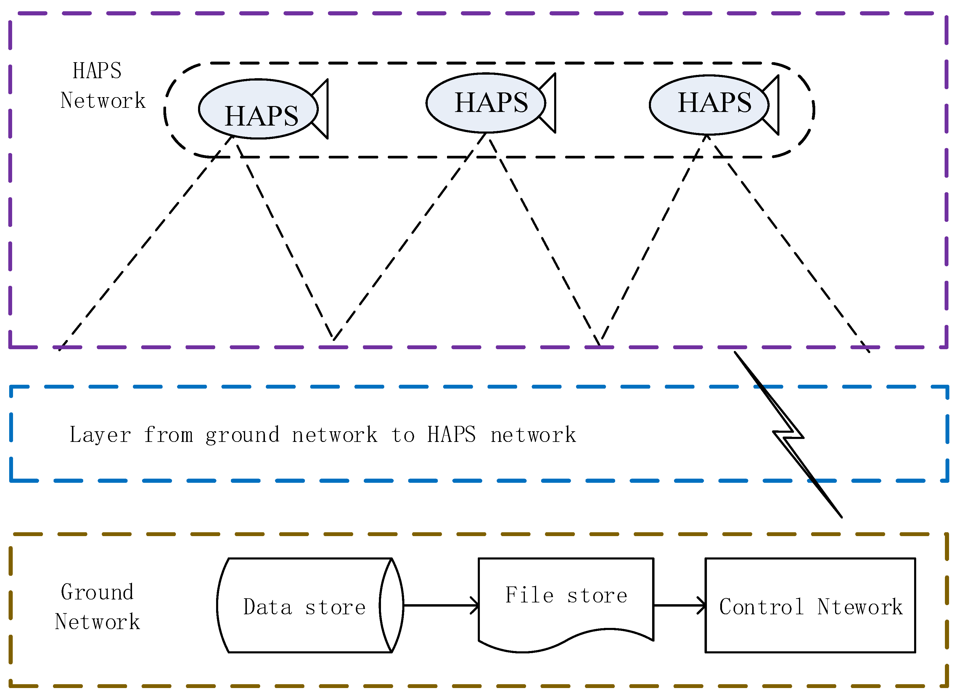
The HAPS-based air-ground integrated aeronautical telecommunication network architecture is shown in Figure 1. The HAPS network includes a set of HAPS communication nodes that can perform routing, forwarding, and traffic management, and microwave communication can be implemented between each HAPS node. The link problem between HAPS is a technical problem, and the geometric relationship of the communication system is shown in Figure 1.
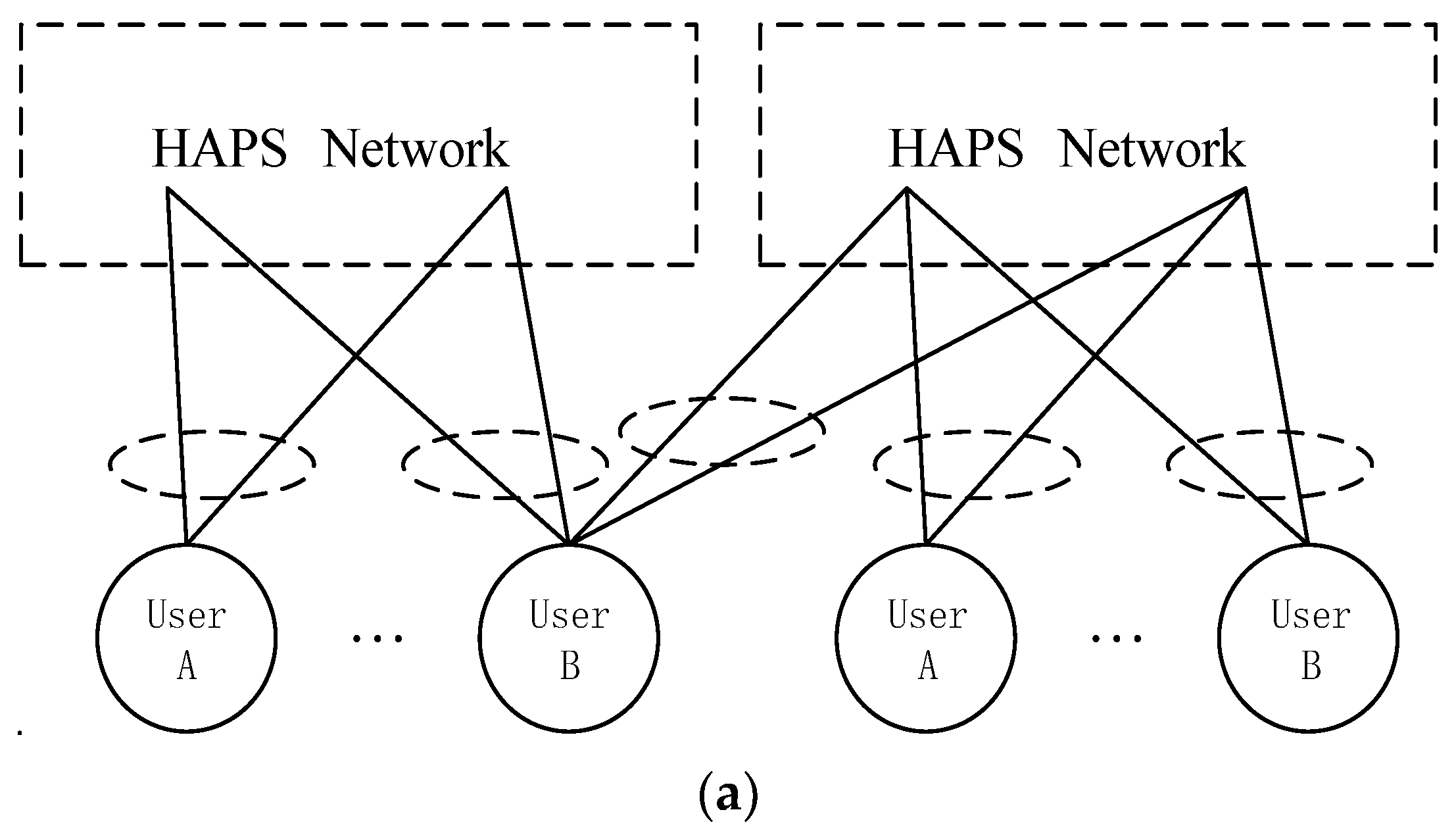
Use a stable communication platform as a microwave relay station in the near-Earth space. a communication system with ground control equipment, entry equipment, and a variety of wireless users. The high-altitude platform can be integrated with the satellite ground or separately from the ground. Consider the communication platform as a synchronous communication satellite, that is, the communication platform is synchronized with the Earth’s rotation. Can stay in the air for a long time. High-altitude platform communication utilizes good radio wave transmission characteristics, realizing communication connections between ground users, between platforms or between platforms and satellites through platforms. It has the advantages of flexible layout, wide application, low cost, safety and reliability. The schematic diagram of the HAPS space communication network is shown in Figure 2.
It can be seen from Figure 2 that HAPS is a highly dynamic space platform. The communication between them is related to the atmospheric environment, multipath fading, space flicker and other factors.
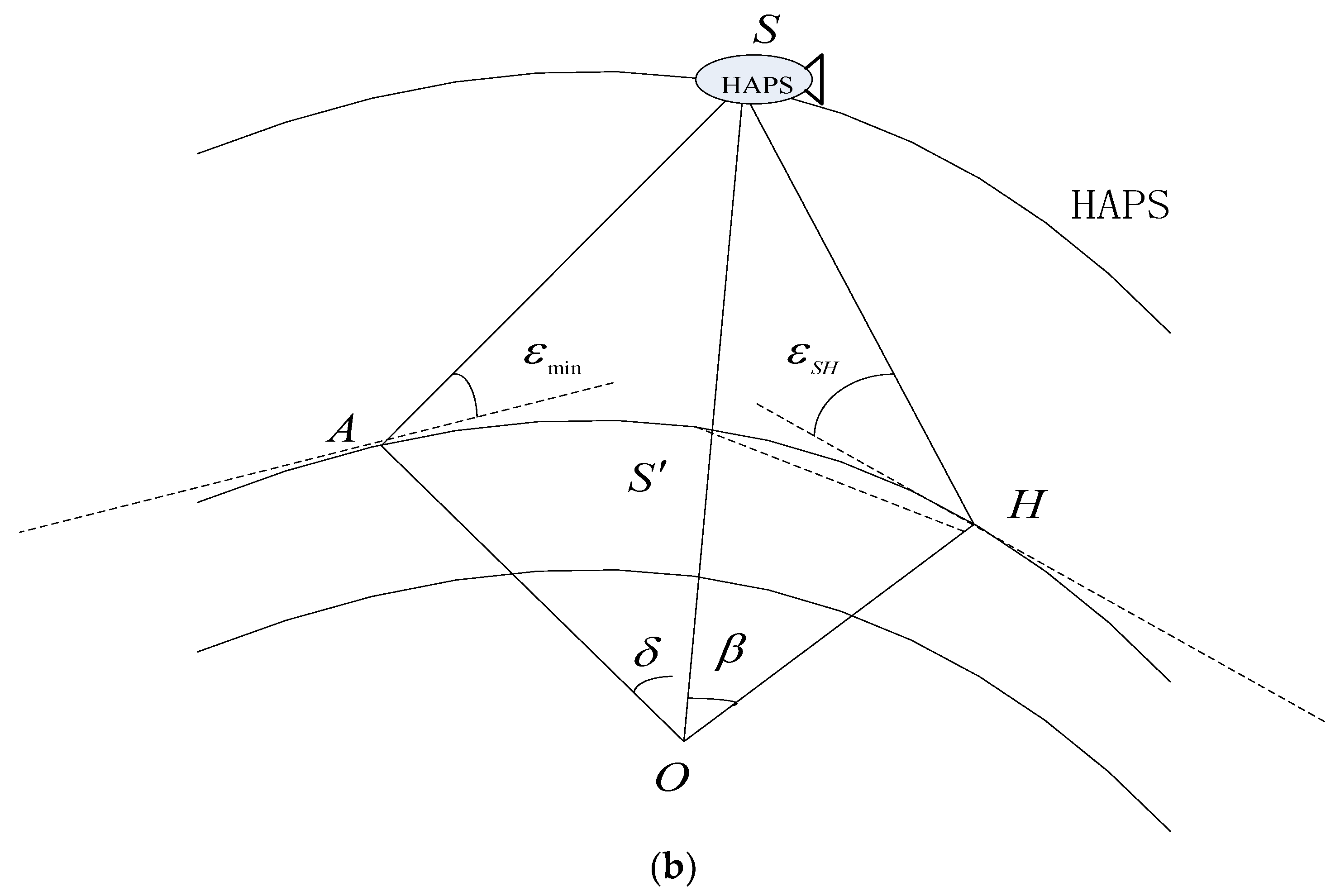
According to the geometric relationship of Figure 2, it can be calculated using the following equation:
where is the radius of earth. is the altitude of HAPS, is the altitude from HAPS to earth ground. is the pitch angle of the HAPS, is the central angle of the HAPS, which can be seen in Figure 2b. According to the geometric relationship, the central angle can be obtained through the following Equation (2).
In Equation (2), the relevant coefficients have been explained in Equation (1).
The central angle of the HAPS can be calculated by the following equation:
where is the distance between HAPS and point . is the radius of earth. is the altitude of HAPS. The pitch angle of the HAPS can be described by the Equation (4).
As can be seen from Equation (4), the pitch angle is related to the central angle , radius of earth , HAPS altitude and (the distance from HAPS to earth ground), it has a nonlinear function relationship. is the distance at time .
where is the i-th slot time, denotes the time step.
3. HAPS Link Budget and Channel Modeling
3.1. HAPS Link Budget
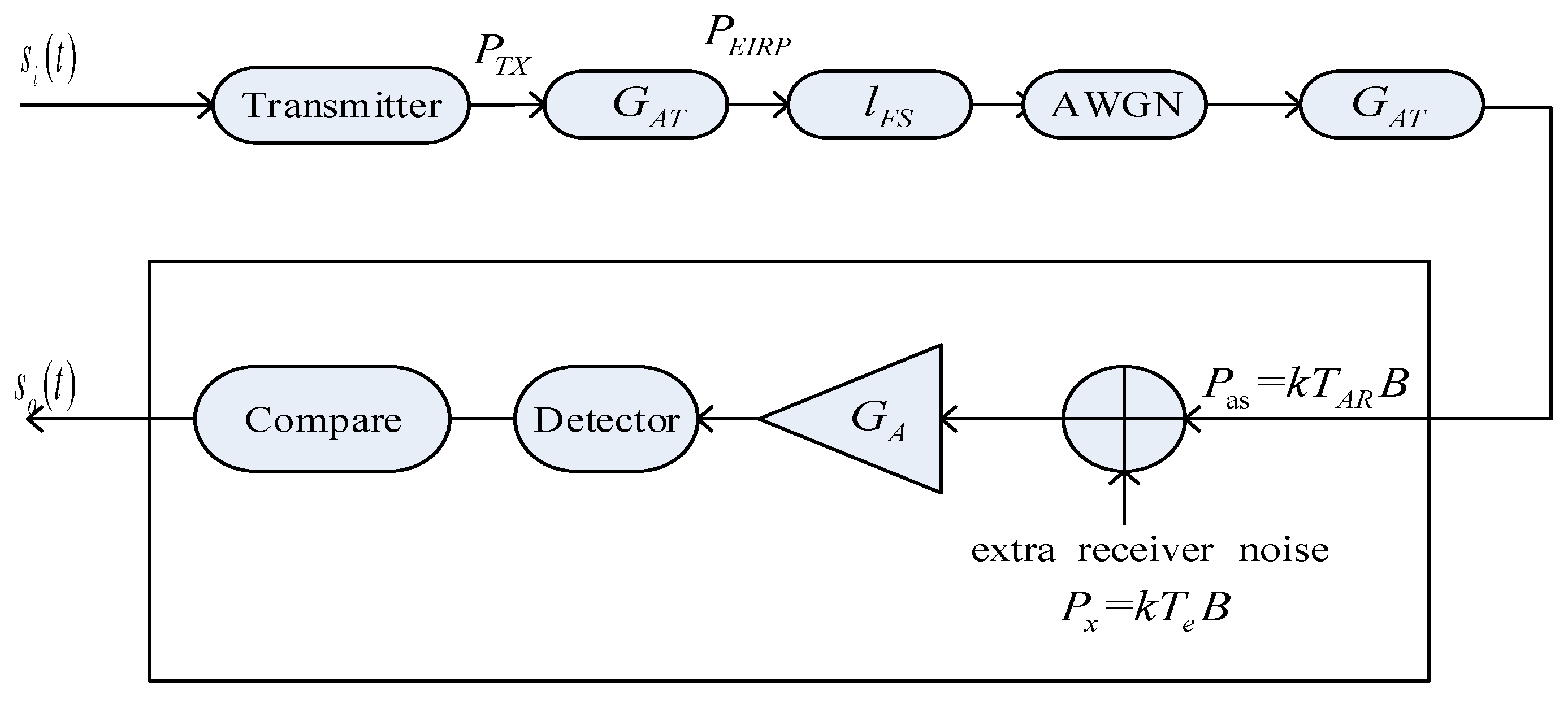
The main goal of the link budget is to ensure the availability of the HAPS communication link. Considering the cost of space segments and ground station equipment, the HAPS link needs to be carefully designed. To fully optimize and save all available resources. The impairment of the HAPS link performance evaluation can be represented by the link diagram shown in Figure 3.
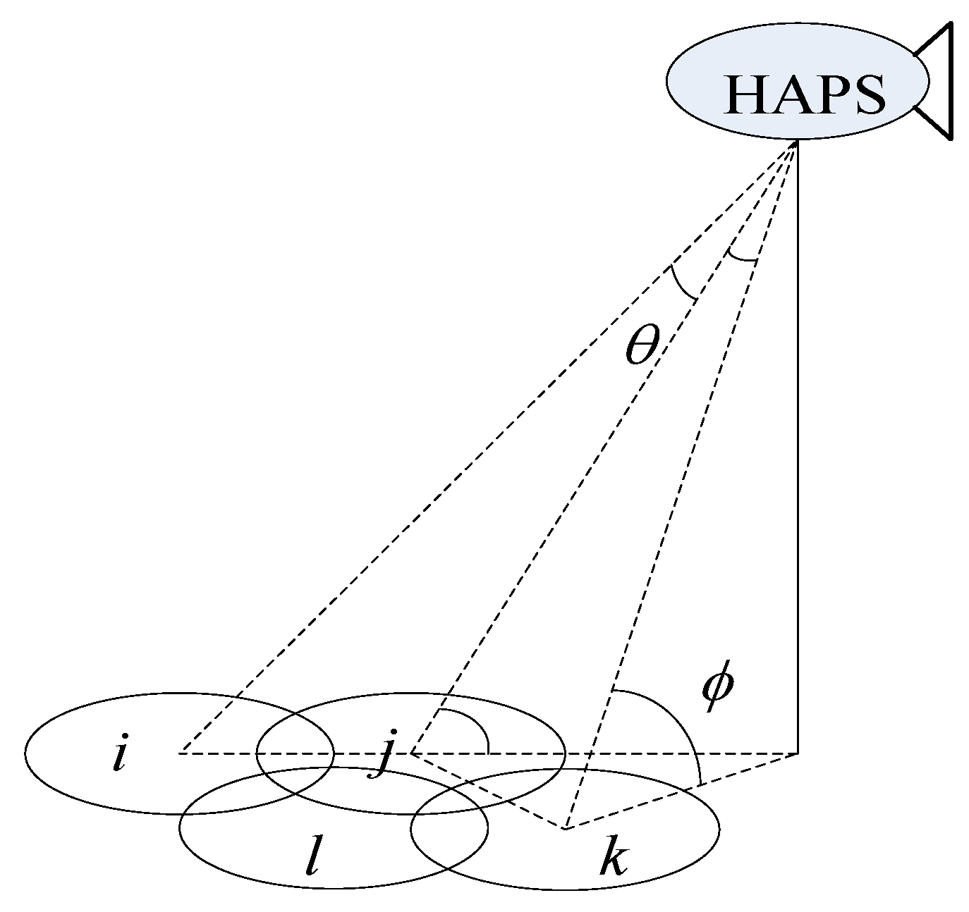
Where, indicates the equivalent isotropic radiated power of the transmitter, AWGN is Additive white Gaussian noise. is the loss of free space, indicates the gain of acceptance antenna. expresses the input signal and denotes the output signal. is the thermal noise power, is Boltzmann constant. is IF (Intermediate Frequency) effective bandwidth. indicates antenna noise temperature, indicates the effective input noise temperature of the overall acceptance system, is the transmit power, denotes the amplifier gain. The uplink interference of the near space HAPS is shown in Figure 4.
As can be seen from Figure 4, for different users , etc., there is interference between them. The smaller the elevation angle is, the longer the distance from the HAPS to its users.
The energy per bit of the near space HAPS can be expressed as:
where is the carrier wave average power. indicates the time it takes to accept 1 bit(s). The signal to noise ratio can be expressed as:
where is the bit rate (b/s). indicates the spent time when transmit 1-bit energy. denotes the thermal noise power spectral density, then can be expressed as:
where represents the equivalent isotropic radiated power of the transmitter. denotes the loss of free space. indicates the antenna gain. is the Boltzmann constant. is the effective temperature in HAPS system. is the radius of earth.
As for 2PSK or QPSK, bit error rate and have the following relationship:
where denotes the error function. For example, .
When the bit error rate is required, the normalized ideal threshold SNR can be described by the following equation:
where is the Boltzmann constant. is the power when receive 1 bit.
The elevation angle of HAPS can be expressed as
where is the central angle of the HAPS. are the elevation angle of two different stations to the HAPS platform, respectively.
In the HAPS wireless communication space, the change relationship of the elevation angle should be considered. The error rate in the un-coded case can be expressed as:
If PSK (8 phase shift keying) and Hamming code (15, 11) and Golay code (23, 12) are used to encode near space HAPS channels, the bit error rate can be expressed as:
where is the bit error rate, the value of is different based on different code mode. is the elevation angle of HAPS.
3.2. Channel Modeling
For the given time slot , the corresponding sub-channel can be arranged in a matrix , its component is. The I/O correspondence of MIMO is
where is dimension noise vector for every time slot . is the input vector with dimension; is the output vector with dimension.
Limited average power and peak power the upper and lower boundaries of the MIMO channel capacity of Equation (15) can be expressed as:
where denotes the entire transmission time period. is the mean value, expresses the transmission power. indicates the maximum number of slot time. is the input vector:
where is the adjustment factor. is the maximum value of the slot time with dimension.
Under the assumption that the input signal satisfies the average power limited Equation (16) and the peak power limited Equation (17), the non-coherent capacity of channel Equation (17) has an upper boundary of , and wireless communication channel capacity can be denoted by the following equation:
where represents the channel bandwidth. indicates the minimum upper bound of one set. For example, is the minimum upper bound of the set . denotes the jitter factor of HAPS platform. expresses the jitter maximum value.
Without loss of generality, can be expressed as:
where denotes the wireless communication signal power. is the noise power. is belong to . If related parameters are obtained, the value of could be calculated.
3.3. Holistic Applicability Analysis
3.3.1. Analysis in the Femtocell
In the process of practical application, clustering has also proved to be an effective method to reduce interference in the femtocell. This method is widely used in ad hoc wireless networks. However, if this method is applied to a femtocell network, it is first necessary to know the number of clusters. The shared registered spectrum band is then divided into m sub-bands, each of which uses a sub-band. Since there are different numbers of femtocells in each cluster, this means different rate requirements. Therefore, the bandwidth allocation of each sub-band will directly affect the performance of the femtocell network. If the number of clusters is large, the bandwidth allocated by each cluster is relatively small. This will not meet the minimum requirements of femtocells. However, when the bandwidth allocated by each cluster is relatively large, the interference between the femtocells cannot be effectively reduced. Therefore, a new method is needed to determine the number of clusters and the bandwidth allocated for each cluster. This will be the next step in this paper.
3.3.2. Impact on the Resource Management in HAPS Wireless Communication System
The goal of wireless communication resource management is to provide service quality assurance for wireless user terminals in the network under limited bandwidth conditions. The basic starting point is that the network traffic is unevenly distributed, and the channel characteristics are fluctuating due to channel weakness and interference. It is necessary for flexible allocation and dynamic adjustment of the available resources of the wireless transmission, maximize wireless spectrum utilization and prevent network congestion and keep the signaling load as small as possible.
One of the main features of the HAPS communication system is the existence of a large number of non-real-time packet data services. Because different users have different rates. The sum of all user rates in a base station tends to exceed the channel capacity that can be transmitted by the base station’s own frequency band. Therefore, it is necessary to have a scheduler in the base station according to the user QoS requirements. The channel resources will be allocated to different users according to the type of service.
4. Discussion
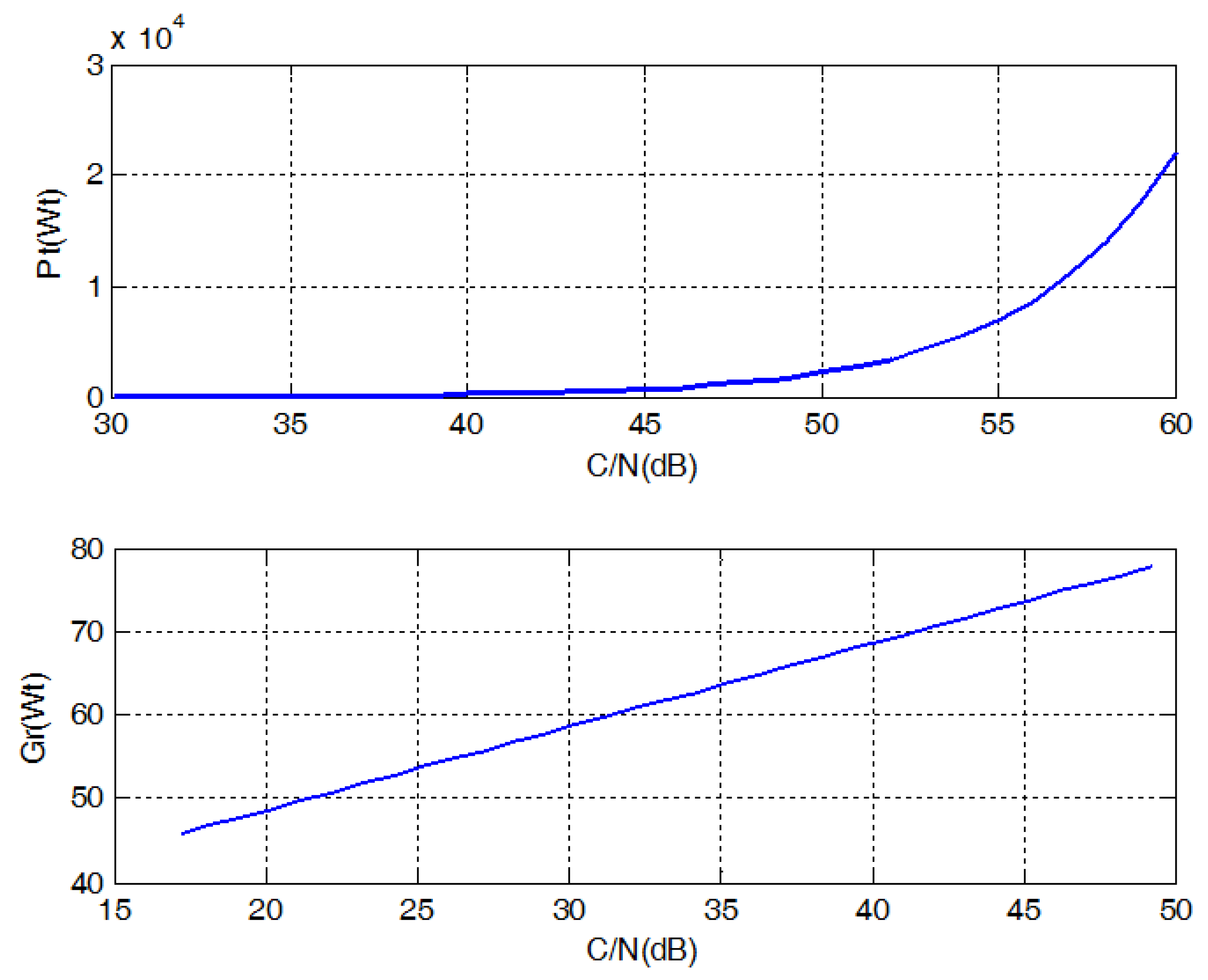
The noise spectral density is normalized by . Transmit power is 0.5 Mw. The level of receiver thermal noise is 200 dBm/Hz. Free space path loss is 10 m. The receiver noise coefficient is 15 dB, is set by 1.
The relationship between the transmit power of the HAPS and the antenna gain at different carrier-to-noise ratios is shown in Figure 5.
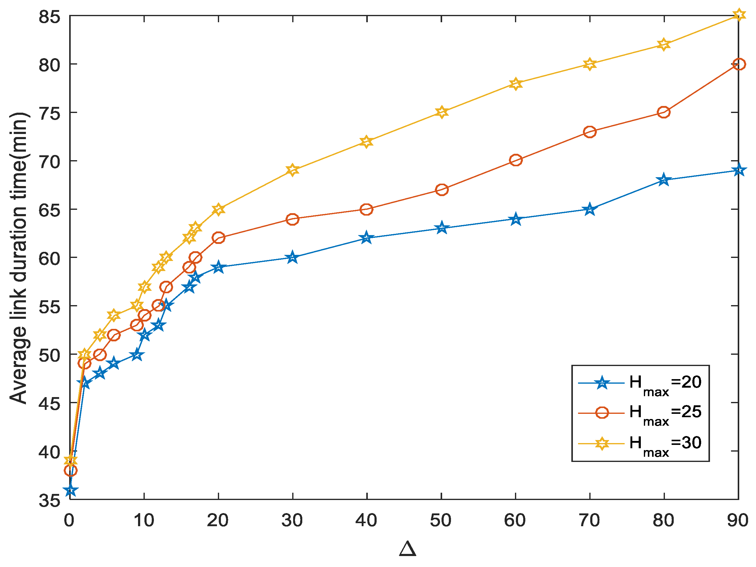
As can be seen from Figure 5, as the carrier-to-noise ratio C/N increases, the transmit power of the HAPS also increases proportionally. At the same time, the antenna gain is also increased with C/N. The duration simulation of the HAPS wireless communication link at different altitudes is shown in Figure 6.
As can be seen from Figure 6, the higher the HAPS space base station, the longer its average link duration. Here the HAPS height is increased from 20 km to 30 km. But the average link duration does not increase linearly, as increases, the average link duration also increases with a non-linear growth trend.
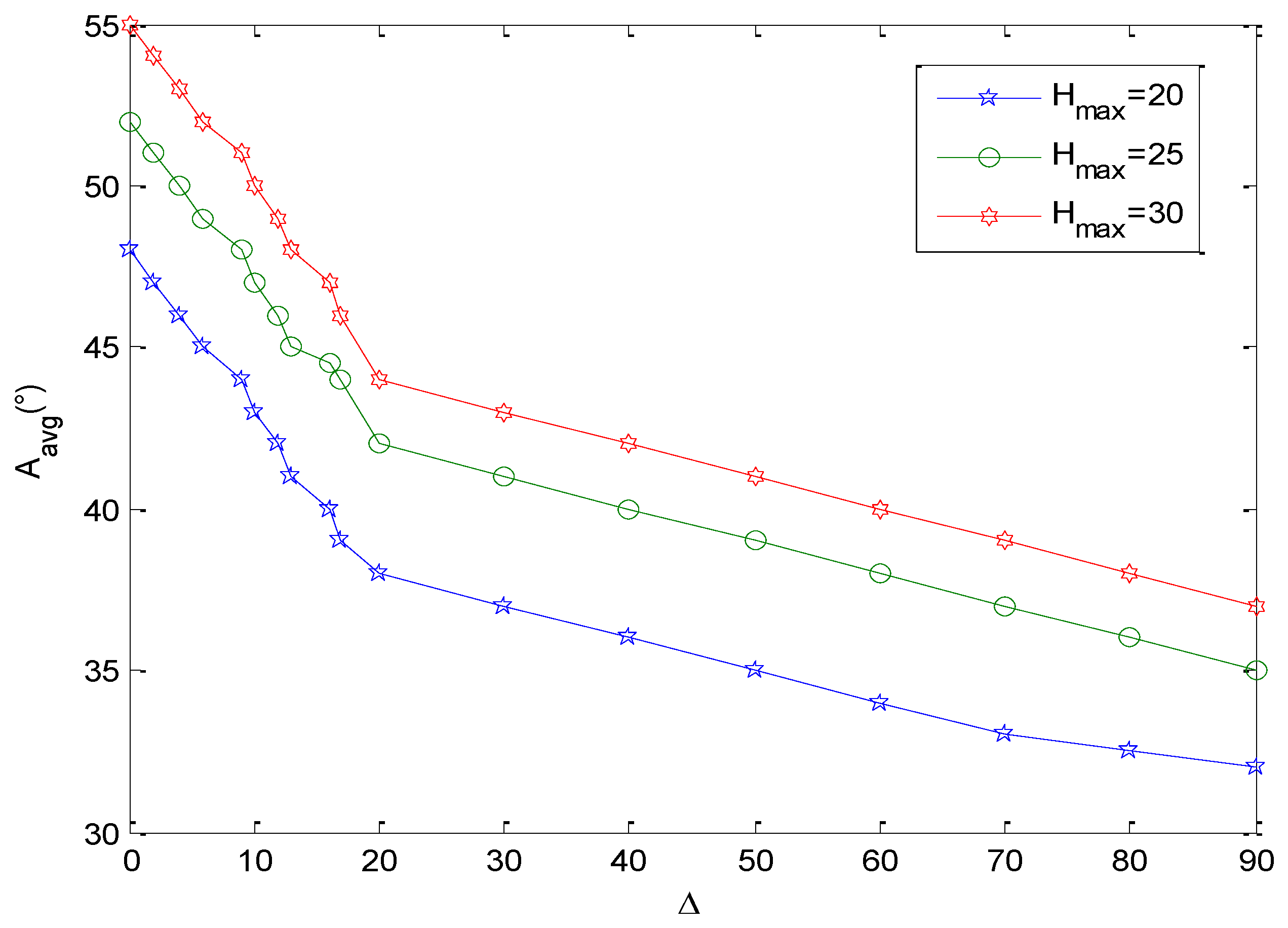
It can be seen from Figure 7 that the higher the HAPS space base station, the higher its elevation angle, and as increases, the elevation angle also increases accordingly. Under the same , the higher the HAPS, the higher the elevation angle.
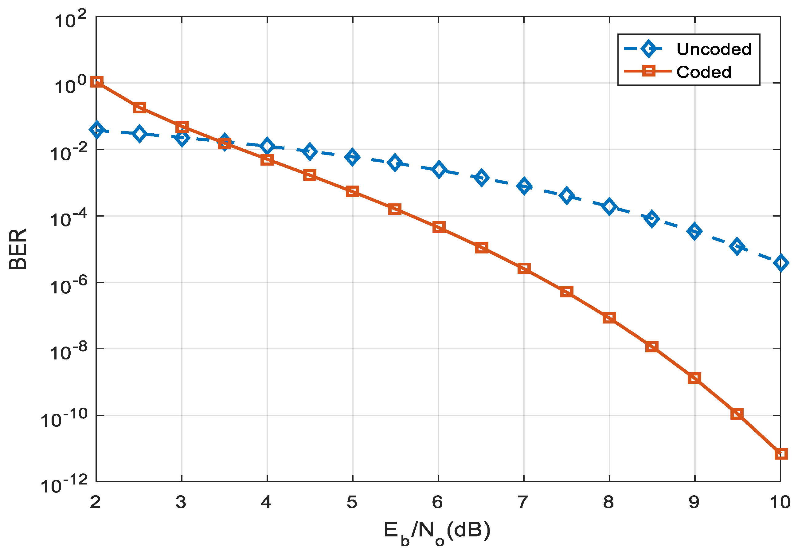
Whether the channel is encoded or not has a large influence on the bit error rate (BER), and its bit error rate at different can be shown in Figure 8.
It can be seen from Figure 8 that when the value of is small, the un-coded performance is better than the coded (8 PSK) channel case; when is greater than 3.5, the coded channel has a bit error rate BER smaller than that of the un-coded channel. Overall, the bit error rate in the coding case is lower than the un-coded.
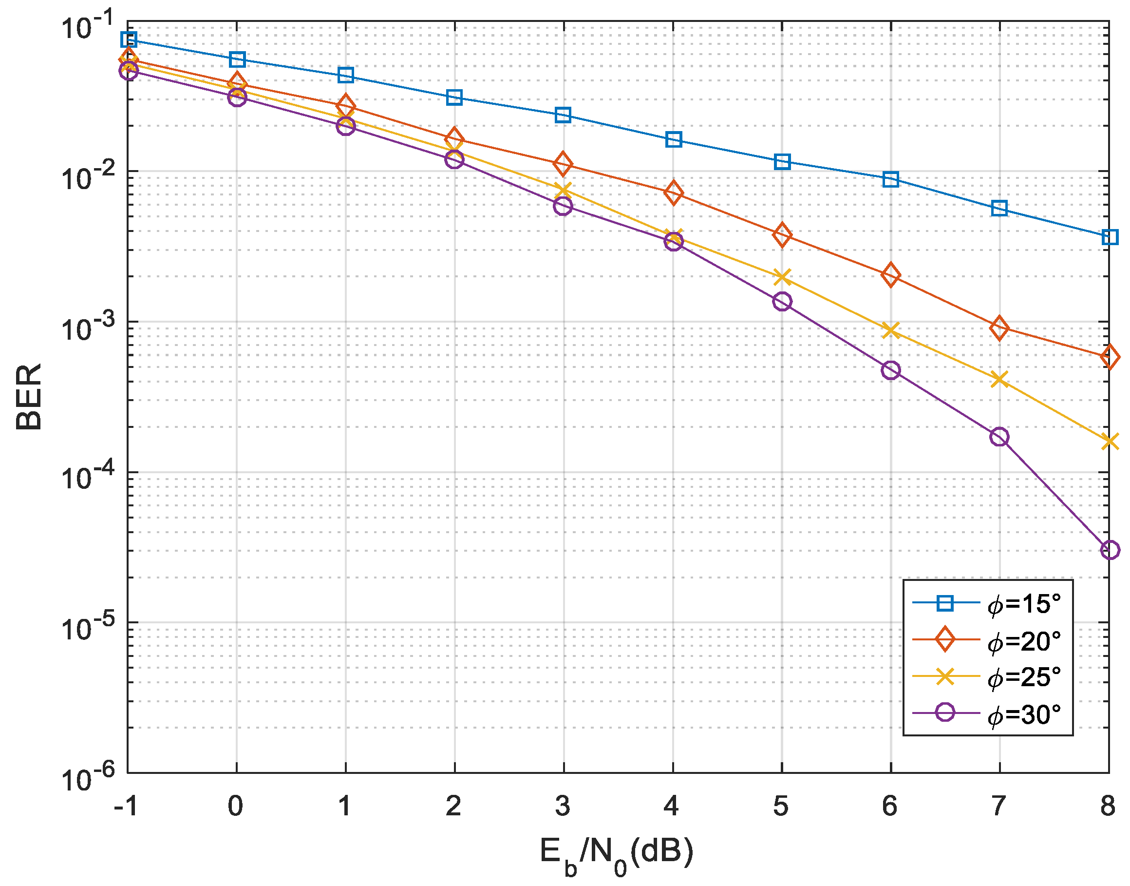
The influence of the elevation angle between the HAPS platform and the user in the near space on the transmission performance of the HAPS cannot be ignored. This is because if the elevation angle is small, the inclination path from the platform to the user will be large. This will increase free space loss and rain attenuation. Therefore, it will affect the HAPS link communication performance. Figure 9 simulates the error rate at different elevation angles .
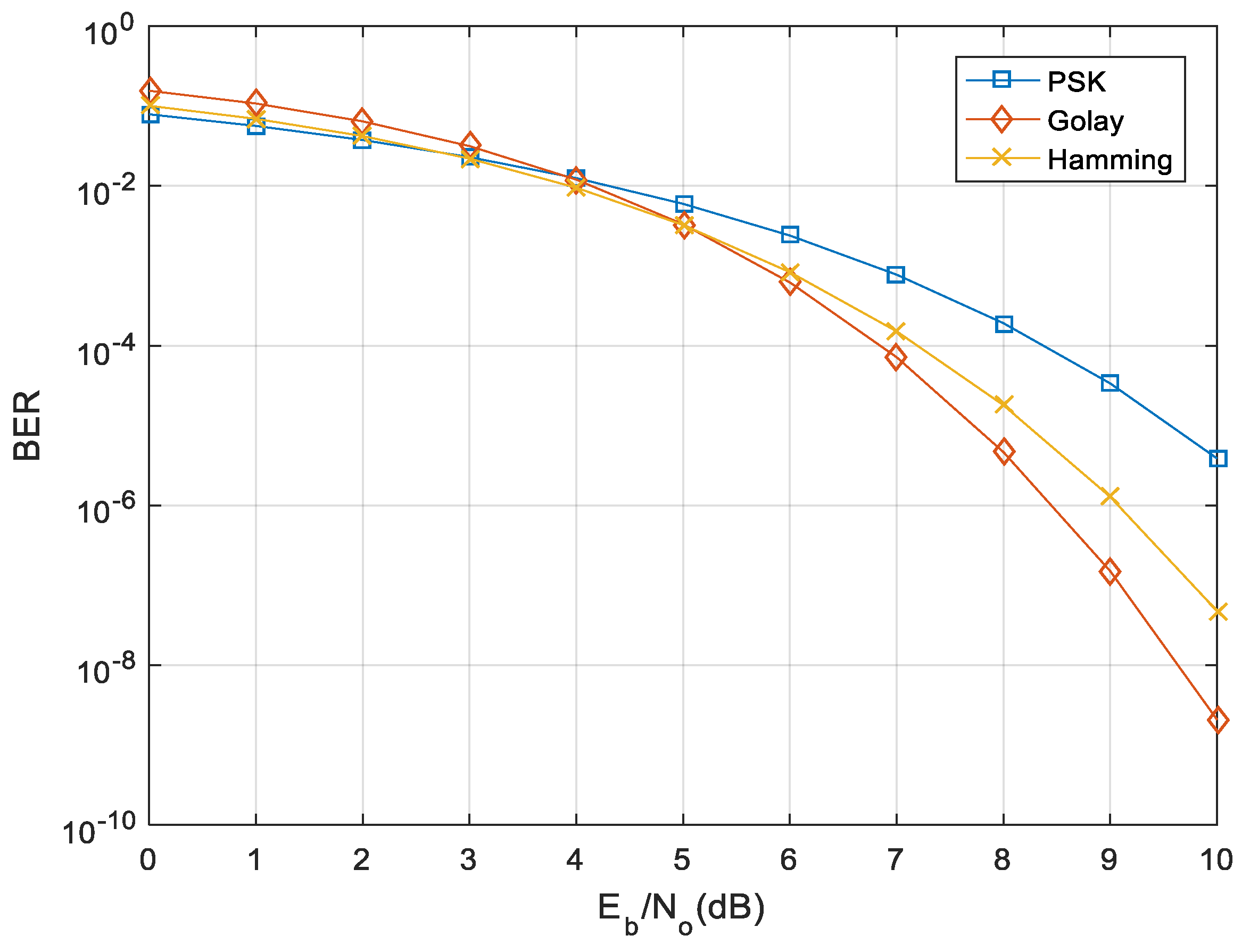
As can be seen from Figure 9, in the case of the same value, the larger the elevation angle , the smaller the bit error rate. When the elevation angle C is 20°, PSK (8 phase shift keying) is used respectively, coding with the Golay code (23, 12) and the Hamming code (15, 11), the simulation results are shown in Figure 10.
It can be seen from Figure 10 that when , the bit error rate of the PSK is lower than the Golay code and the Hamming code; when , the bit error rate of the Golay code is lower than the PSK and Hamming codes.
5. Conclusions
The characteristics of the near space HAPS are analyzed under the fast time-varying channel. The HAPS link budget mathematical model and wireless communication channel model are proposed respectively. The bit error rate under different HAPS elevation angles, signal to noise ratios are considered in this paper. The simulation results show that the greater the signal-to-noise ratio, the greater the gain and transmission power of the HAPS link. The bit error rate of the link channel in the coding case is better than that of the un-coded one. The key technical issue to be studied in the next step is to describe the time-varying network in terms of duration. Multi-source multi-suspension capacity model of HAPS link and super-radius overlapping coverage scene of near space interference domain capacity model.
Author Contributions
The authors performed the experiments and analyzed the results together. Introduction, methodology, cosmetic detection algorithms and proposed model were written by X.L. and H.L.; while data collection, experimental results and conclusion sections were written by C.L. and Y.L.
Funding
This research was funded by National Planning Office of Philosophy and Social Science of China (No. 17XXW004), Young Fund Project of Humanities and Social Sciences Research of Ministry of Education of China (No. 16YJC860010), Social Science of Humanity of Chongqing Municipal Education Commission (No. 17SKG144), Science and Technology Research Program of Chongqing Municipal Education Commission (No. KJ1600923, No. KJ17092060, No. KJ1600928), 2018 Chongqing Science and Technology Commission Technology Innovation and Application Demonstration Project (No. cstc2018jscx-msybX0049). Natural Science Foundation of China (No. 61503052, No. 61571069, No. 61501065, No. 61502064). Open Fund Project of Chongqing Technology and Business University, Research Center of Chongqing University Network Public Opinion and Ideological Dynamic (No. KFJJ2017024). China Postdoctoral Science Foundation (No. 2017M612911), Research Foundation of the Natural Foundation of Chongqing City (No. cstc2016jcyjA0076). The author Xiaoyang Liu also thanks for the financial support from CSC (China Scholarship Council, No. 201608505142).
Acknowledgments
The authors are grateful to editors and anonymous referees for their very valuable comments and suggestions, which have significantly helped improve the quality of this paper.
Conflicts of Interest
The authors declare no conflict of interest.
References
- Zhang, M.; Atkinson, D.J.; Ji, B.; Armstrong, M. A near-state three-dimensional space vector modulation for a three-phase four-Leg voltage source inverter. IEEE Trans. Power Electron. 2014, 29, 5715–5726. [Google Scholar] [CrossRef]
- Sgardoni, V.; Nix, A.R. Raptor code-aware link adaptation for spectrally efficient unicast video streaming over mobile broadband networks. IEEE Trans. Mob. Comput. 2015, 14, 401–415. [Google Scholar] [CrossRef]
- Chen, G.; Chen, B.; Li, P.; Bai, P.; Ji, C. Study of aerodynamic configuration design and wind tunnel test for solar powered buoyancy-lifting vehicle in the near-space. Procedia Eng. 2015, 99, 67–72. [Google Scholar] [CrossRef]
- Su, J. Near space as a sui generis zone: A tri-layer approach of delimitation. Space Policy 2013, 29, 90–92. [Google Scholar] [CrossRef]
- Jiang, B.; Xu, D.; Shi, P.; Lim, C.C. Adaptive neural observer-based back stepping fault tolerant control for near space vehicle under control effect or damage. IET Control Theory Appl. 2014, 8, 658–666. [Google Scholar] [CrossRef]
- Baccour, N.; Koubâa, A.; Youssef, H.; Alves, M. Reliable link quality estimation in low-power wireless networks and its impact on tree-routing. Ad Hoc Netw. 2015, 27, 1–25. [Google Scholar] [CrossRef]
- Vu, M.Q.; Nguyen, N.T.; Pham, H.T.; Dang, N.T. All-optical two-way relaying free-space optical communications for HAP-based broadband backhaul networks. Opt Commun. 2018, 410, 277–286. [Google Scholar] [CrossRef]
- Gu, W. HAPS multi-scale perceptual routing algorithm for networks. J. Beijing Univ. Posts Telecommun. 2012, 35, 52–55. (In Chinese) [Google Scholar]
- Han, L.; Li, L. Integrated wireless communications and wireless power transfer: An overview. Phys. Commun. 2017, 25, 555–563. [Google Scholar] [CrossRef]
- Wang, Y.; Ertürk, M.C.; Liu, J.; Ra, I.H.; Sankar, R.; Morgera, S. Throughput and delay of single-hop and two-hop aeronautical communication networks. J. Commun. Netw. 2015, 17, 58–66. [Google Scholar] [CrossRef]
- Arnau, J.; Christopoulos, D.; Chatzinotas, S.; Mosquera, C.; Ottersten, B.E. Performance of the multi-beam satellite return link with correlated rain attenuation. IEEE Trans. Wirel. Commun. 2014, 13, 6286–6299. [Google Scholar] [CrossRef]
- Ammari, H.M. Investigating the energy sink-hole problem in connected k-covered wireless sensor networks. IEEE Trans. Comput. 2014, 63, 2729–2742. [Google Scholar] [CrossRef]
- Jiang, Y. HAPS-CDMA system hotspot area uplink capacity improvement plan. J. PLA Univ. Sci. Tech. 2014, 15, 514–518. (In Chinese) [Google Scholar]
- Yuan, Y.; Zhang, Y.; Liu, Z.; Guan, X. Lossless coding scheme for data acquisition under limited communication bandwidth. Digital Signal Process 2017, 69, 204–211. [Google Scholar] [CrossRef]
- Perlaza, S.M.; Tandon, R.; Poor, H.V.; Han, Z. Perfect output feedback in the two-user decentralized interference channel. IEEE Trans. Inf. Theory 2015, 61, 5441–5462. [Google Scholar] [CrossRef]
- Cai, K.; Yin, Z.; Jiang, H.; Tan, G.; Guo, P.; Wang, C.; Li, B. Onionmap: A scalable geometric addressing and routing scheme for 3d sensor networks. IEEE Trans. Wirel. Commun. 2015, 14, 57–68. [Google Scholar] [CrossRef]
- Lu, S.; Wang, Z.; Wang, Z.; Zhou, S. Throughput of underwater wireless ad hoc networks with random access: A physical layer perspective. IEEE Trans. Wirel. Commun. 2015, 14, 6257–6268. [Google Scholar] [CrossRef]
- Yashchyshyn, Y.; Derzakowski, K.; Bajurko, P.R.; Marczewski, J.; Kozłowski, S. Time-modulated reconfigurable antenna based on integrated s-pin diodes for mm-wave communication systems. IEEE Trans. Antennas Propag. 2015, 63, 4121–4131. [Google Scholar] [CrossRef]
- Ismaiel, A.M.; Elsaidy, E.; Albagory, Y.; Atallah, H.A.; Abdel-Rahman, A.B.; Sallam, T. Performance improvement of high altitude platform using concentric circular antenna array based on particle swarm optimization. AEU-Int. J. Electron. Commun. 2018, 91, 85–90. [Google Scholar] [CrossRef]
- Sudheesh, P.G.; Sharma, N.; Magarini, M.; Muthuchidambaranathan, P. Effect of imperfect CSI on interference alignment in multiple-High Altitude Platforms based communication. Phys. Commun. 2018, 29, 336–342. [Google Scholar]
- Chiba, K.; Nishikawa, R.; Onda, M.; Satori, S.; Akiba, R. Aerodynamic influences on a tethered high-altitude lighter-than-air platform system to its behavior. Aerosp. Sci. Technol. 2017, 70, 405–411. [Google Scholar] [CrossRef]
- Jesús, G.; Deibi, L.; Diego, D.; Adrián, G.; Alberto, E. On the capabilities and limitations of high altitude pseudo-satellites. Prog. Aerosp. Sci. 2018, 98, 37–56. [Google Scholar]
- Mohammad, I.A.; Rajkumar, S.P. Multi-objective multidisciplinary design analyses and optimization of high altitude airships. Aerosp. Sci. Technol. 2018, 78, 248–259. [Google Scholar]
- Zhuxian, L.; Lingge, J.; Chen, H. A 3-D GBSM based on isotropic and non-isotropic scattering for HAP-MIMO channel. IEEE Commun. Lett. 2018, 22, 1090–1093. [Google Scholar]
- Sudheesh, P.G.; Mozaffari, M.; Magarini, M.; Saad, W.; Muthuchidambaranathan, P. Sum-rate analysis for High Altitude Platform (HAP) drones with tethered balloon relay. IEEE Commun. Lett. 2018, 22, 1240–1243. [Google Scholar] [CrossRef]
- Lian, Z.; Jiang, L.; He, C. A 3-D wideband model based on dynamic evolution of scatterers for HAP-MIMO channel. IEEE Commun. Lett. 2017, 21, 684–687. [Google Scholar] [CrossRef]
- Yang, M.; Zhang, S.; Shao, X.; Guo, Q.; Tang, W. Statistical modeling of the high altitude platform dual-polarized MIMO propagation channel. China Commun. 2017, 14, 43–54. [Google Scholar] [CrossRef]
- Barillas, L.; Cubero-Sesin, J.M.; Vargas-Blanco, I. Hydroxyapatite coatings on polymers using a custom low-energy plasma spray system. IEEE Trans. Plasma Sci. 2018, 46, 2420–2424. [Google Scholar] [CrossRef]
- Ji, X.; Xu, J.; Che, Y.L.; Fei, Z.; Zhang, R. Adaptive Mode switching for cognitive wireless powered communication systems. IEEE Wirel. Commun. Lett. 2017, 6, 386–389. [Google Scholar] [CrossRef]
- Yuan, L.; Bi, S.; Zhang, S.; Lin, X.; Wang, H. Multi-antenna enabled cluster-based cooperation in wireless powered communication networks. IEEE Access 2017, 5, 13941–13950. [Google Scholar] [CrossRef]
- Mishra, D.; De, S.; Krishnaswamy, D. Dilemma at RF energy harvesting relay: downlink energy relaying or uplink information transfer? IEEE Trans. Wirel. Commun. 2017, 16, 4939–4955. [Google Scholar] [CrossRef]
- Chen, X.; Yi, J.; Li, J.; Zhou, J.; Wang, Z. Soft-actuator-based robotic joint for safe and forceful interaction with controllable impact response. IEEE Robot. Autom. Lett. 2018, 3, 3505–3512. [Google Scholar] [CrossRef]
- Chen, Y.; da Costa, D.B.; Ding, H. Interference Analysis in Wireless Power Transfer. IEEE Commun. Lett. 2017, 21, 2318–2321. [Google Scholar] [CrossRef]
- Alotaibi, S.; Akl, R. Self-adjustment downlink transmission power for femtocells in co-channel deployment in heterogeneous networks. In Proceedings of the 2017 IEEE 7th Annual Computing and Communication Workshop and Conference (CCWC), Las Vegas, NV, USA, 9–11 January 2017; pp. 1–6. [Google Scholar]
- Eirini, E.T.; Georgios, K.K.; Panagiotis, V.; Symeon, P. Efficient uplink power control in multi- service two-tier femtocell networks via a game theoretic approach. In Proceedings of the IEEE International Workshop on Computer-Aided Modeling Analysis and Design of Communication Links and Networks (CAMAD), Berlin, Germany, 25–27 September 2013; pp. 104–108. [Google Scholar]
- Sheikhzadeh, S.; Mokari, N.; Saeedi, H. Radio resource allocation for interference management in OFDMA-based femtocell-macrocell deployment. In Proceedings of the 2016 24th Iranian Conference on Electrical Engineering (ICEE), Shiraz, Iran, 10–12 May 2016; pp. 757–761. [Google Scholar]
- Tsiropoulou, E.E.; Vamvakas, P.; Papavassiliou, S. Supermodular game-based distributed joint uplink power & rate allocation in two-tier SC-FDMA femtocell networks. IEEE Trans. Mob. Comput. 2017, 16, 2656–2667. [Google Scholar]
- Khamidehi, B.; Sabbaghian, M.; Saeedi, H. Power allocation in uplink LTE femtocells with zero forcing frequency domain equalizer. In Proceedings of the 2016 IEEE Wireless Communications and Networking Conference, Doha, Qatar, 3–6 April 2016; pp. 1–6. [Google Scholar]
- Tsiropoulou, E.E.; Vamvakas, P.; Katsinis, G.K.; Papavassiliou, S. Combined power and rate allocation in self- optimized multi-Service two-tier femtocell networks. Comput. Commun. 2015, 72, 38–48. [Google Scholar] [CrossRef]
Figure 1.
System frame diagram of the High Altitude Platform Station (HAPS).

Figure 2.
Space network diagram and link geometry of HAPS. (a) Network diagram; (b) Geometry diagram.
Figure 2.
Space network diagram and link geometry of HAPS. (a) Network diagram; (b) Geometry diagram.


Figure 3.
Sketch map of HAPS link budget.

Figure 4.
Uplink interference model of HAPS.

Figure 5.
The transmitted power and antenna gain under different carrier noise ratio.

Figure 6.
Average link duration time.

Figure 7.
Relationship between elevation angles at different HAPS altitudes.

Figure 8.
The BER (Bit Error Rate) under different encoding.

Figure 9.
The BER (Bit Error Rate) under different elevation angle.

Figure 10.
The BER (Bit Error Rate) under different PSK, Golay, Hamming.

© 2018 by the authors. Licensee MDPI, Basel, Switzerland. This article is an open access article distributed under the terms and conditions of the Creative Commons Attribution (CC BY) license (http://creativecommons.org/licenses/by/4.0/).
Share and Cite
MDPI and ACS Style
Liu, X.; Liu, H.; Liu, C.; Luo, Y. Time-Varying Communication Channel High Altitude Platform Station Link Budget and Channel Modeling. Information 2018, 9, 210. https://0-doi-org.brum.beds.ac.uk/10.3390/info9090210
AMA Style
Liu X, Liu H, Liu C, Luo Y. Time-Varying Communication Channel High Altitude Platform Station Link Budget and Channel Modeling. Information. 2018; 9(9):210. https://0-doi-org.brum.beds.ac.uk/10.3390/info9090210
Chicago/Turabian StyleLiu, Xiaoyang, Hengyang Liu, Chao Liu, and Ya Luo. 2018. "Time-Varying Communication Channel High Altitude Platform Station Link Budget and Channel Modeling" Information 9, no. 9: 210. https://0-doi-org.brum.beds.ac.uk/10.3390/info9090210
Note that from the first issue of 2016, this journal uses article numbers instead of page numbers. See further details here.