The Selected Issues of Adaptation of 19th and 20th Century Post-Industrial Buildings in Łódź †


Department of Concrete Structures, Lodz University of Technology, 90-924 Łódź, Poland
*
Author to whom correspondence should be addressed.
†
The paper includes some selected issues presented during REHABEND 2020 Congress.
Infrastructures 2020, 5(8), 69; https://0-doi-org.brum.beds.ac.uk/10.3390/infrastructures5080069
Submission received: 29 July 2020
/
Revised: 14 August 2020
/
Accepted: 15 August 2020
/
Published: 18 August 2020
(This article belongs to the Special Issue Selected Papers from the REHABEND 2020 Congress)
Abstract
:The paper deals with selected technical problems related to the adaptation for new uses of the structure of existing post-industrial buildings from the turn of the 19th and 20th centuries. A major difficulty is the fact that the strength and geometric properties of cast-iron, steel, and masonry elements often differ significantly from the values characterizing contemporary materials. Due to uncertainty regarding the load-carrying capacity of historical structures, in many cases there is a need to carry out destructive tests of elements taken from the buildings. As the example of cast-iron girders in the former spinning mill of “I. Poznański” demonstrated, such tests can prove a significant margin of load-carrying capacity and confirm the possibility of adapting the structure to new purposes. The paper also presents examples of strengthening the existing wooden ceilings by joining with the reinforced concrete structure, which allowed the keeping of the original elements and an increase of the allowable load. Selected problems related to the assessment of historical masonry structures were also described. The discussed examples of structural failures showed that they often resulted from incorrect assessment of the strength of historical masonry elements as well as improperly conducted construction works.
1. Introduction
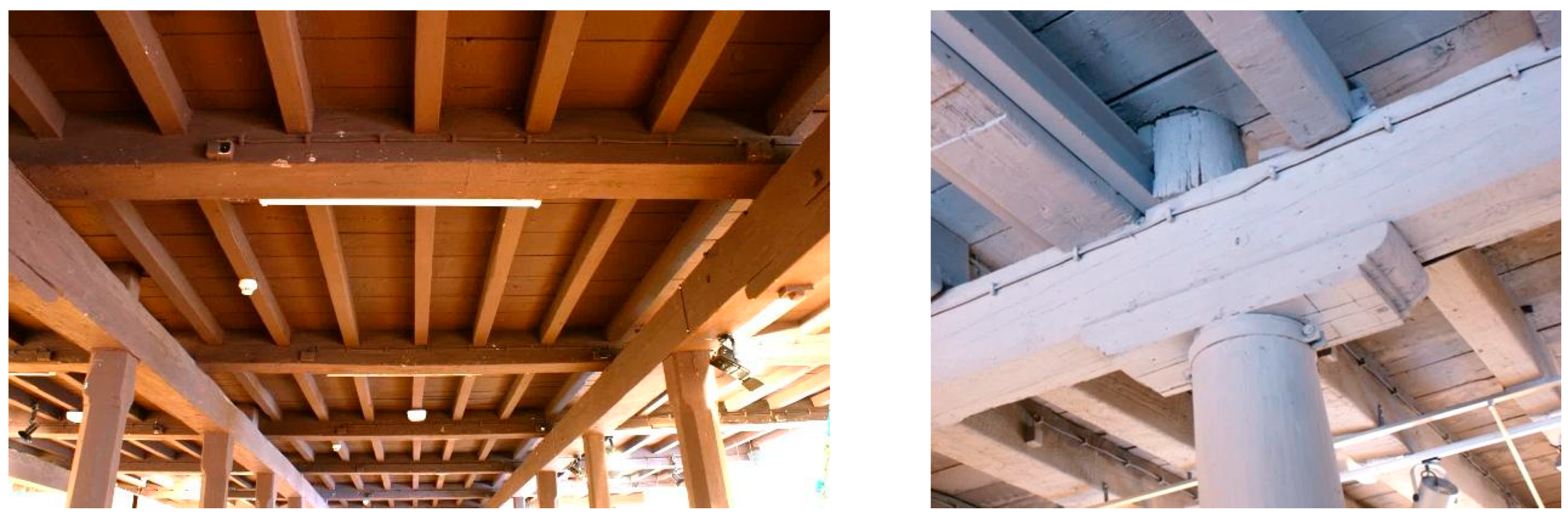
Significant technological progress related to the invention of the steam engine in the second half of the 18th century began the era of the industrial revolution connected with intensive industrialization. New needs required the construction of industrial buildings on an unprecedented scale. Until 1780, the main form of load-bearing structure of multi-storey industrial and warehouse buildings were wooden ceilings, with beams supported on masonry walls and two or three rows of wooden columns—see Figure 1 [1]. The beam span between columns and walls was from 3 to 4 m. Still this skeletal structure was not immune to fire. Fires in factories threatened not only workers but also expensive materials, machines, and buildings themselves. Flammable materials, such as cotton fibers or cotton dust, combined with the vapors of oil used to lubricate machines and the use open flame lamps or sparks produced by metal machines, created an environment favorable to the expansion of fire. The skeletal structure additionally created a new type of threat that did not occur in buildings with masonry load-bearing walls, consisting in a progressive collapse. The local failure of one column on the lower storey resulted in the collapse of all floors above. Such an accident took place in March 1791 in the London factory “Albion Flour Mill” designed by “Samuel Wyatt” and regarded as an outstanding industrial facility at that times.
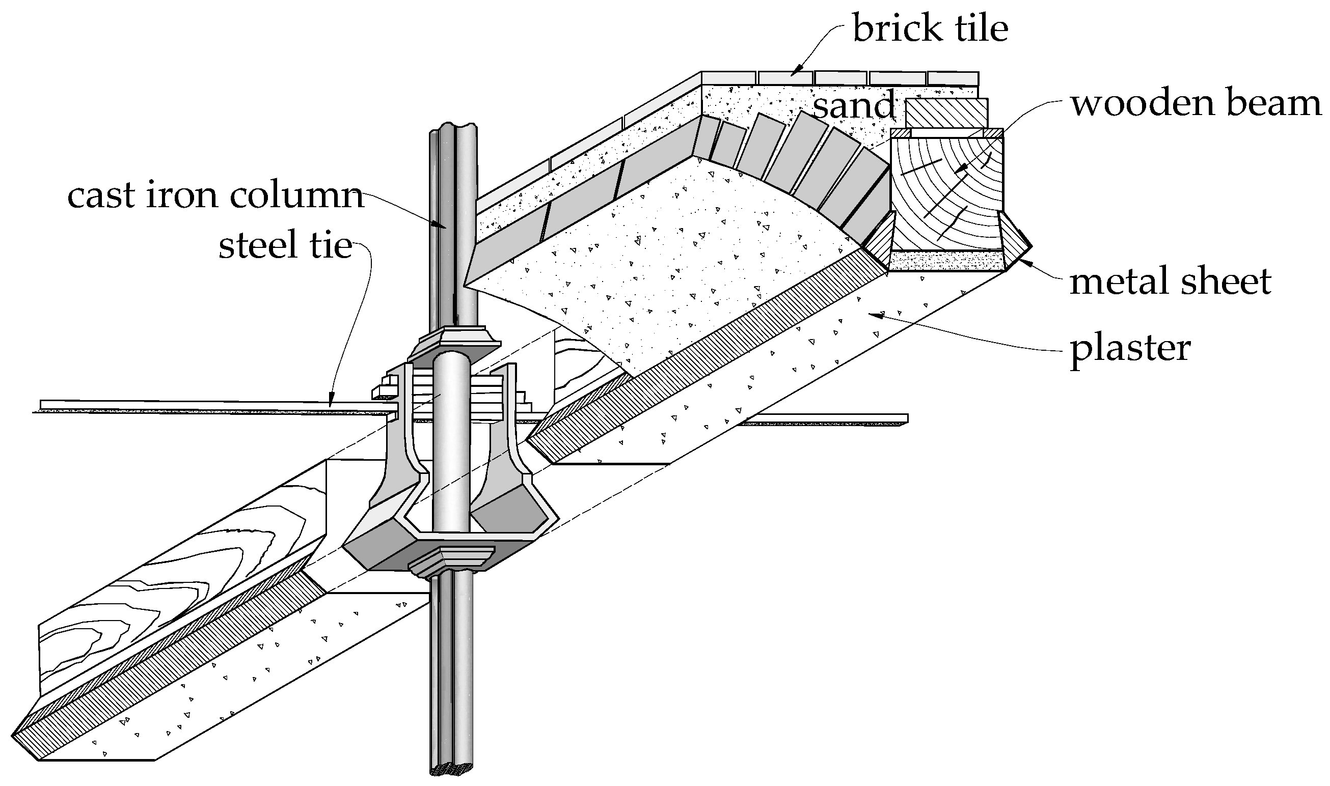
The destructive effects of fires were the main reason to look for new structural solutions. One of such idea was introduced by “William Strutt”, an English industrialist and engineer, the first structure resistant to fire conditions (today we would qualify it rather as a structure that does not spread fire). The sketch of structural system was shown in Figure 2 [2]. The ceilings were made in the form of brick arches stretched between the wooden beams, which were supported on cast-iron column with a cruciform cross section. On the underside the wooden beams were protected with steel sheet and plastering mortar. From the top, the fire protection in form of sand covering and ceramic tiles was provided.
As a result of technological progress, cast-iron was introduced to the engineering practice. This material was known before, but only the revolutionary invention of “Abraham Darby I” made it possible to spread. He developed in 1709, a method of casting cast-iron in a blast furnace using coke instead of charcoal. Due to the required precision in the selection of iron ore and fuel, the invention did not initially attract wide interest among metallurgists. The first use of cast-iron on a wider scale took place in 1775, during construction of the bridge over the Severn River. The descendant of the inventor, “Abraham Darby II”, used a huge blast furnace with coke as a fuel. The builder of the bridge was “Abraham Darby III”, who is credited with making the work to the end, because the author of the project, “Pritchard”, died in 1777. The opening of the bridge, currently inscribed on the UNESCO World Heritage List, took place in 1779.
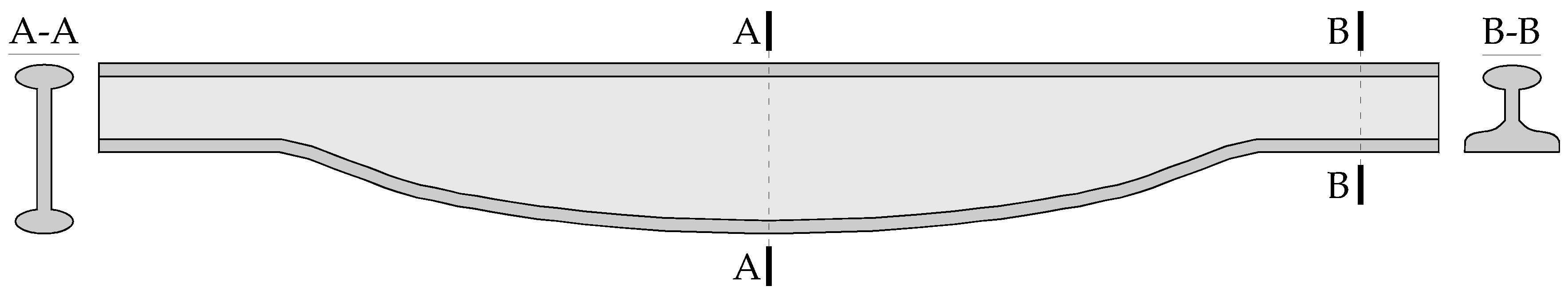
Cast-iron enabled making casts, and thus manufacturing the structural elements of almost any shape. In 1789, English engineer “William Jessop” patented the shape of a cast-iron beam in the form of a fish-belly, referring to the course of bending moments in a simply supported beam—see Figure 3.
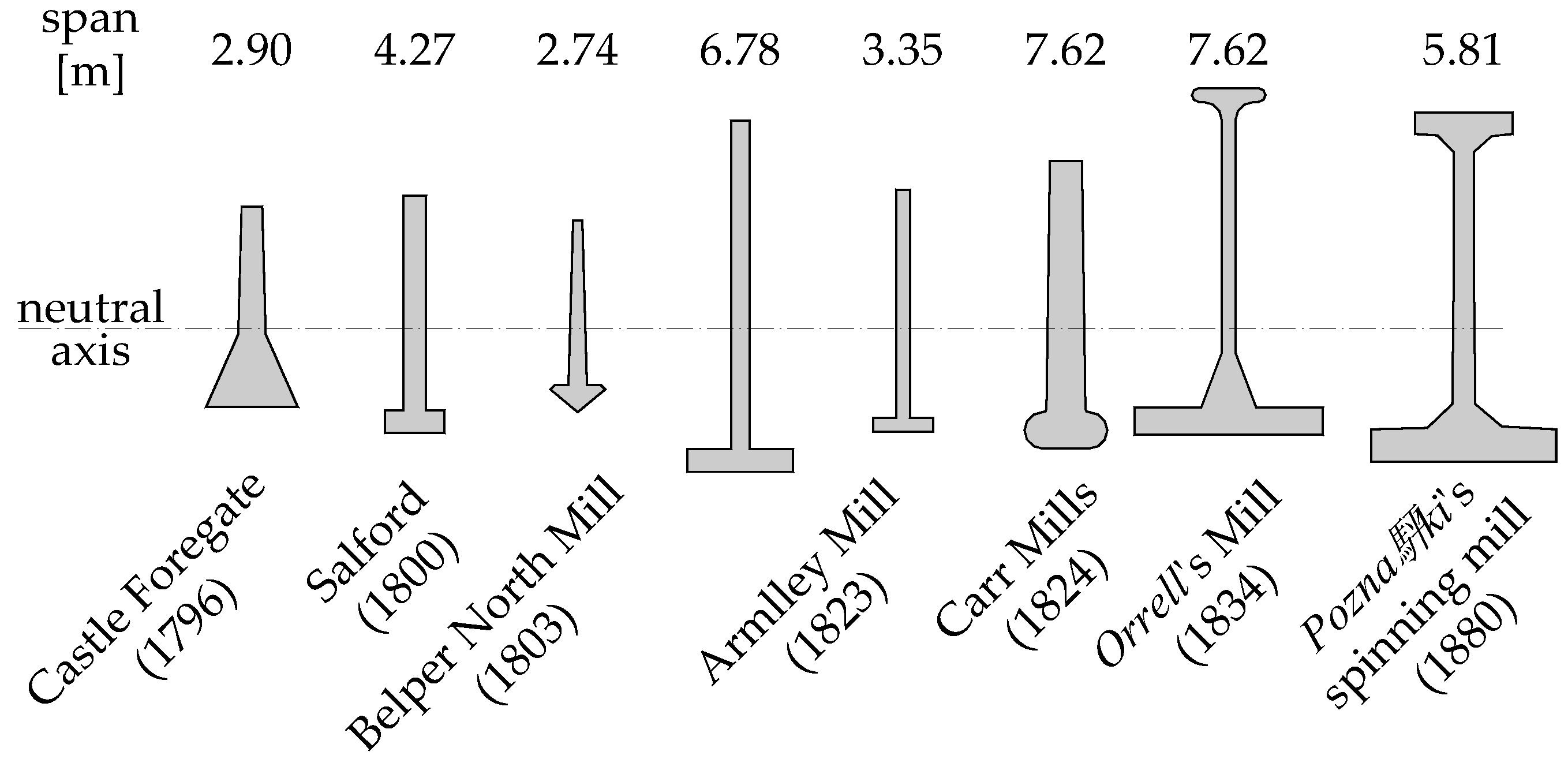
“Eaton Hodgkinson”, an English mathematician, approached the problem to develop a bending beam model subjected to a transverse load. He assumed that the model should take into account only the physical properties of the material, the size of the loads and the dimensions of the beam, without the need to use any empirical parameters. The greatest achievement of Hodgkinson was the development that the place of zeroing the stress in the bending section (neutral axis) coincides with the centre of gravity of this cross-section. In this way it was possible to indicate the most economical material distribution, which was the inverted “T” cross-section. Taking into account the mechanical properties of cast-iron, the cross-sectional areas of the tensioned and compressed parts should be inversely proportional to the ratio of tensile and compressive strength, which is approximately 1:6. Figure 4 shows the shapes of cast-iron beams developed on the basis of Hodgkinson’s theory over the years.
Among the elements presented above, the beam used in “Orrell’s” mill deserves particular attention. It was designed by “William Fairbairn” who, using the theoretical works of Hodgkinson, reduced the consumption of iron from 20 to 30% in relation to the cross-sections used at that time. In this beam, in addition to the asymmetric cross-section, the upper flange was introduced for the first time, limiting the effect of lateral torsional buckling. This cross-section has been disseminated and was also used at the Poznański’s factory in Łódź.
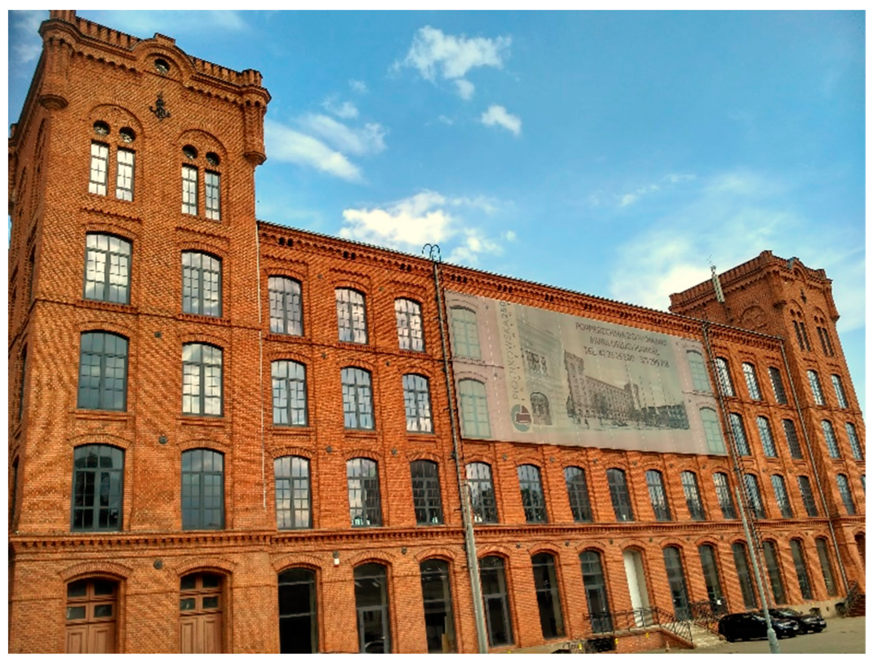
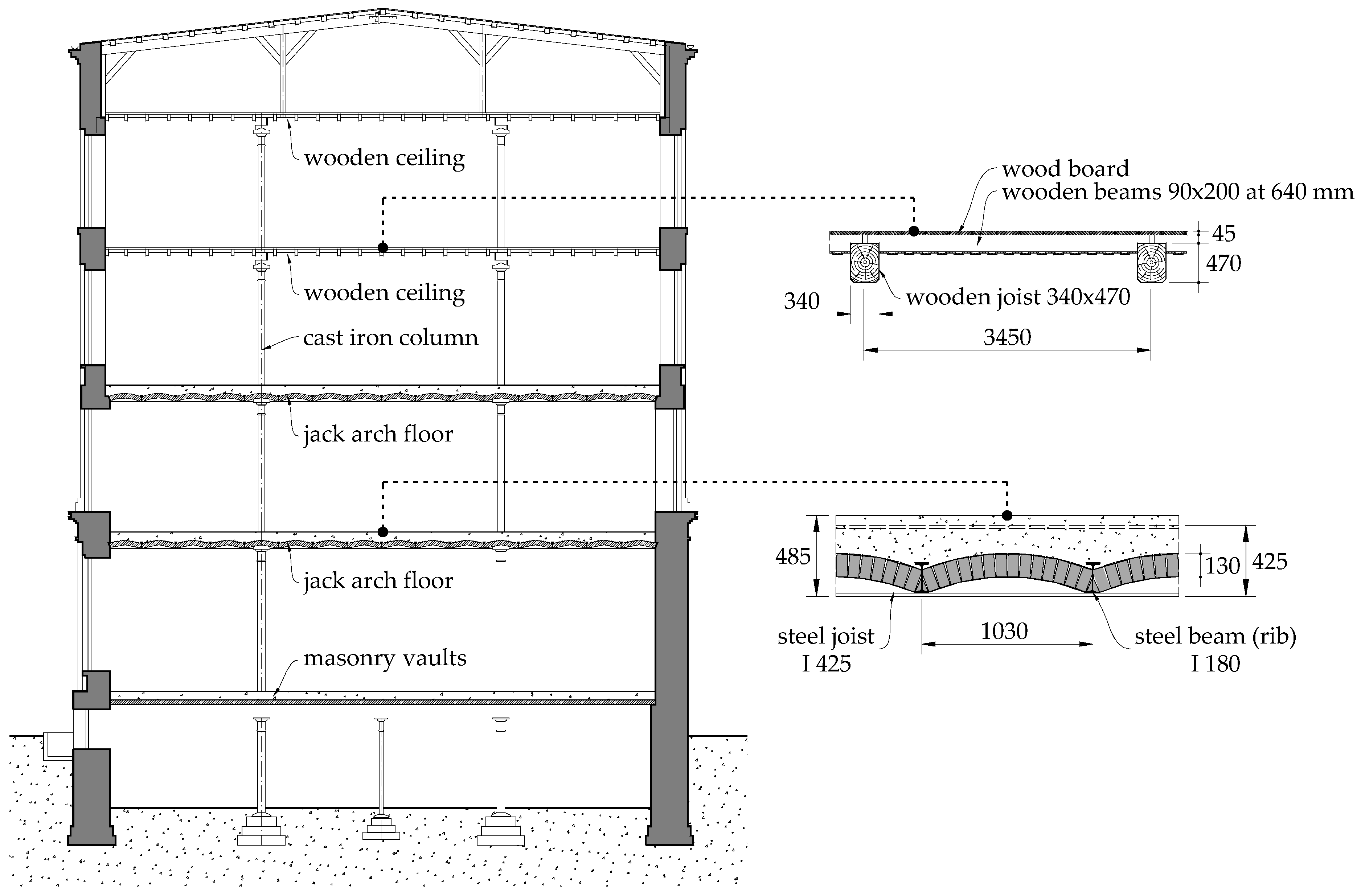
The previously described solutions were commonly used in the 19th century factory facilities in Łódź, adapted mainly to the needs of light industry. An example is the former “Markus Silberstein” cotton and wool factory, erected in 1896, according to the design of Adolf Zeligson—see Figure 5. The structure of this building consisted in masonry walls with a varying thickness of 1.11 m in the basement, 0.97 m on the ground floor, 0.83 m on the first floor, 0.69 m on the second and third floors, and 0.55 m in the attic. Three different types of ceilings were made. Above the basement, brick vaults with an arch span of 3.45 m supported on steel beams were used. Ceilings above the ground floor and the first floor consisted in jack arch floors while wooden ceilings above the second and third floors were constructed—see Figure 6. The joists situated in the transverse direction were supported on the cast-iron columns and anchored in masonry external walls with steel bolts and cast iron anchor blocks.
2. Rehabilitation of Cast-Iron Girders of the Poznański’s Factory in Łódź
2.1. Short Background
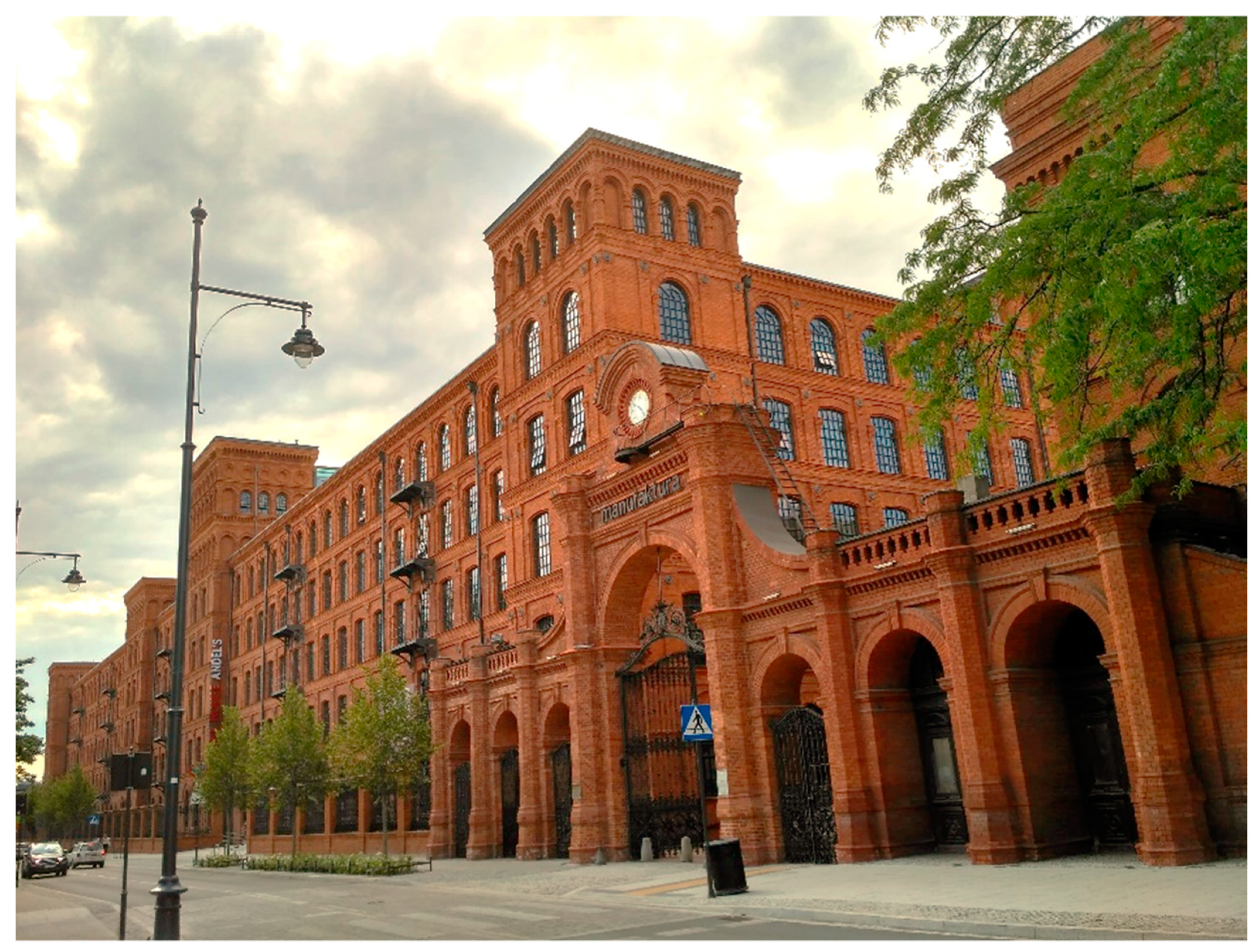
Most contemporary design procedures do not include materials from which historical objects were made. For this reason, the structural designer or expert is forced to use the rules applicable at the time of erecting the building (see [3,4]). Due to the limited state of knowledge, these rules very often turned out to be conservative and their use made it impossible to meet the conditions of ultimate limit state of the structure. In such a case, it seems reasonable to evaluate the load-carrying capacity of the structure by means of experimental investigations. Such a need occurred during the reconstruction of the former Izrael Poznański’s spinning mill in Łódź which was to be intended for a hotel—see Figure 7.
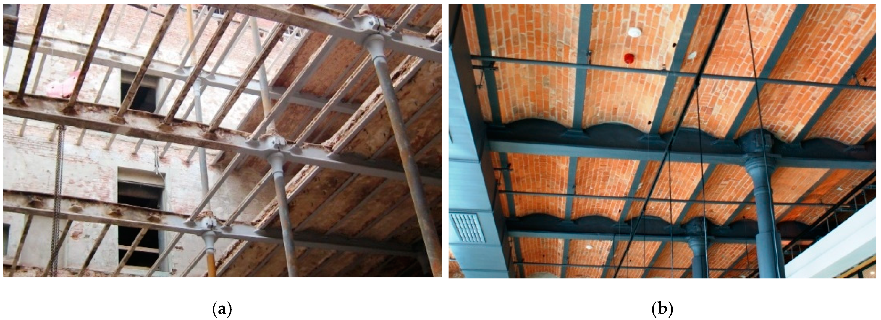
This building was erected in the years 1878–1880. It is a masonry building with five above-ground storeys, and a partial basement. Jack arch floors supported on cast-iron girders were used, which were based on cast-iron columns and masonry external walls. The span in the transverse direction of the building is 6.0 m, and the spacing of the girders along the longitudinal axis is 3.27 m. Steel beams (ribs) with a rail cross-section (probably recovered rails) are supported on the cast-iron girders. The spacing of the secondary beams is about 0.86 m. The building is currently located in the “Manufaktura” complex in Łódź, and from 2009 performs hotel functions (Andel’s Hotel). Figure 8 shows a fragment of the building structure during the reconstruction works and after their completion.
2.2. Experimental Investigations
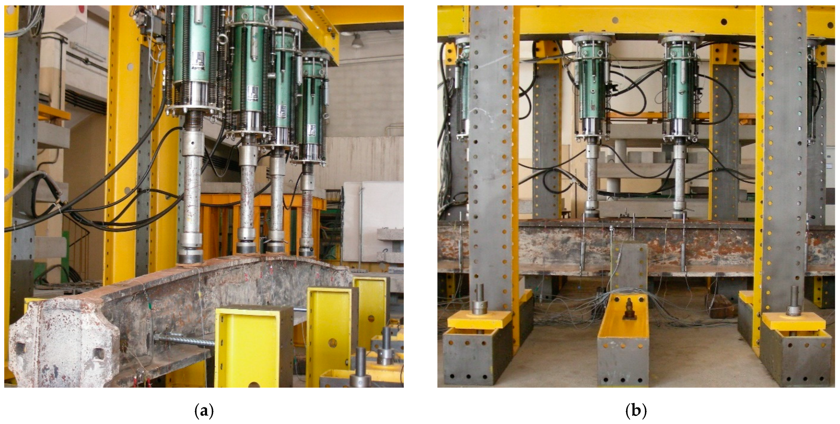
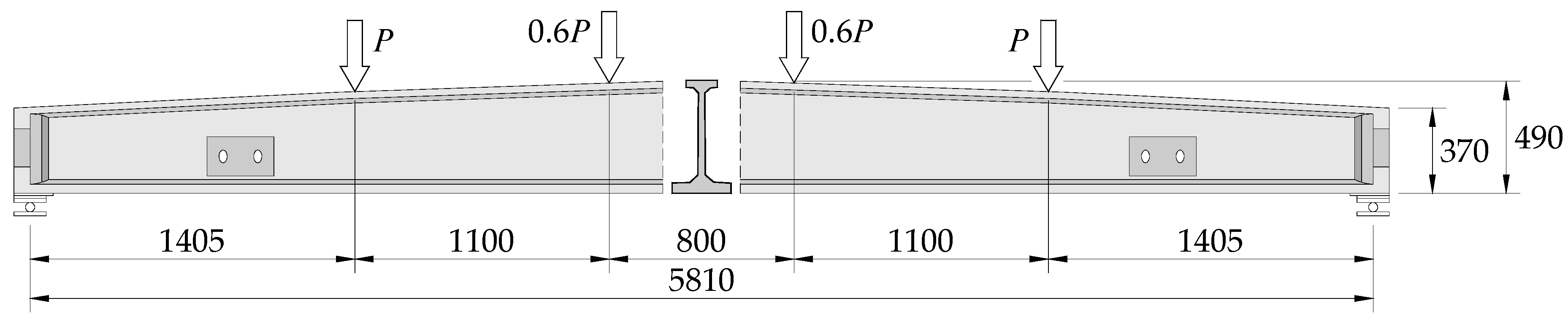
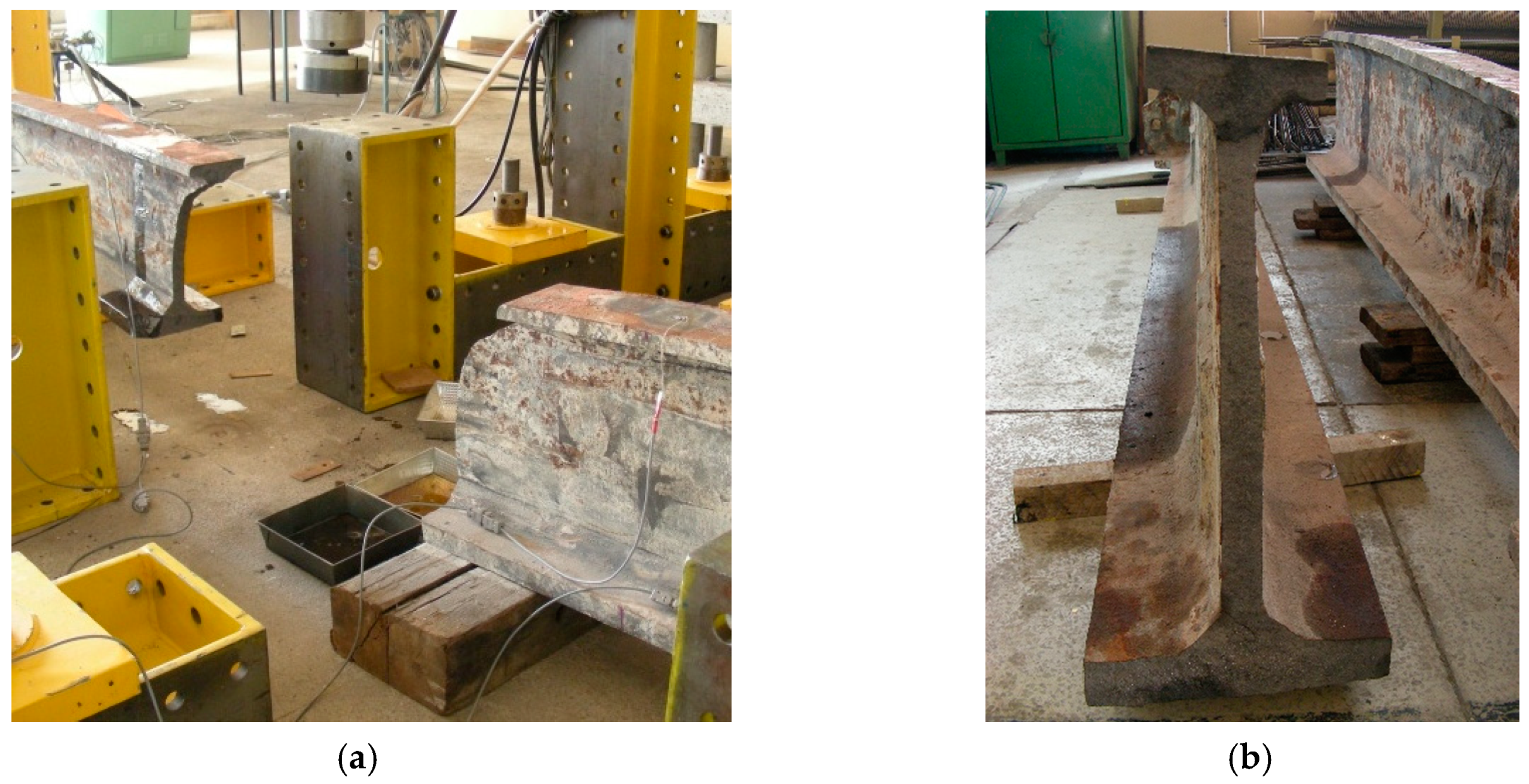
The cross-section of I-beam girders was adjusted to the course of bending moments resulting from uniformly distributed load. The aim of the destructive tests [5] was to determine the allowable load of these structural elements. Two girders were taken from the existing structure, which were then tested in the Laboratory of the Department of Concrete Structures at Lodz University of Technology. In order to reflect the actual way of load as closely as possible, the tests were carried out in a six-point system (girder loaded with four point loads by means of hydraulic jacks)—see Figure 9 and Figure 10.
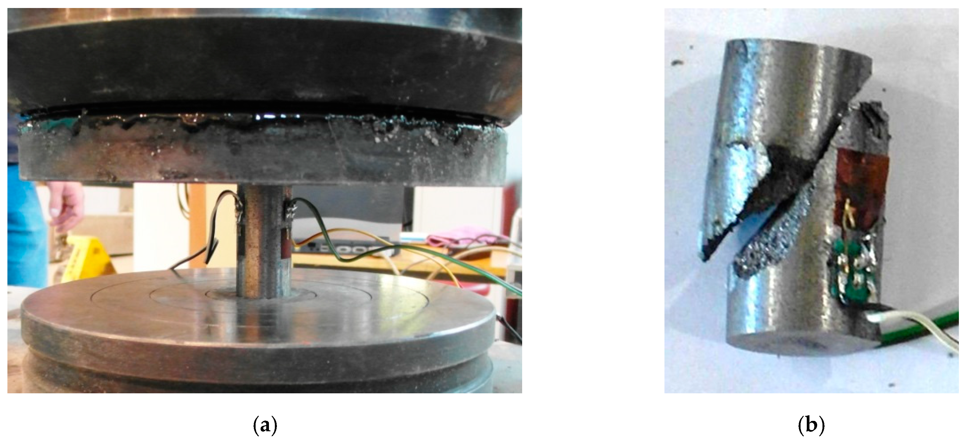
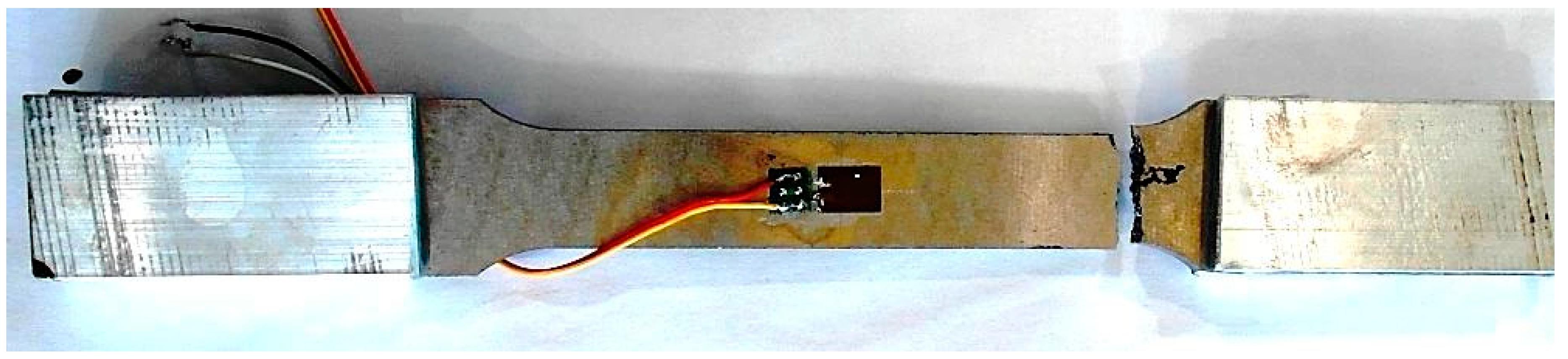
A number of destructive tests were also carried out in the laboratory to determine the mechanical properties of cast-iron—see Figure 11 and Figure 12. The average tensile strength from six samples was Rt = 128 MPa with a coefficient of variation COV = 4.7%, and the compressive strength Rc = 526 MPa with a significantly lower COV = 2.1%. The ratio of tensile to compressive strength was 1:4. At this point, it is worth noting a significant difference between the strength characteristics of cast-iron and contemporary structural steel. Currently, the most popular steel grades are S235–S355 with a yield strength of 215–355 MPa—the same by compression tension. Due to the significant difference between the compressive and tensile strength of cast-iron, as well as the lack of a yield plateau, contemporary design rules for steel structures cannot be applied directly. For example, in the case of cast-iron columns, it was recommended in [6] to reduce the overall instability coefficient by 10–70% compared to steel columns of the same slenderness.
The failure of the compressed cast-iron sample took place in a manner characteristic for a brittle material. At failure cracks on the side surfaces, inclined at an angle close to 45° with respect to the sample axis were observed. They defined the shear-slip plane, which can be visible in Figure 11.
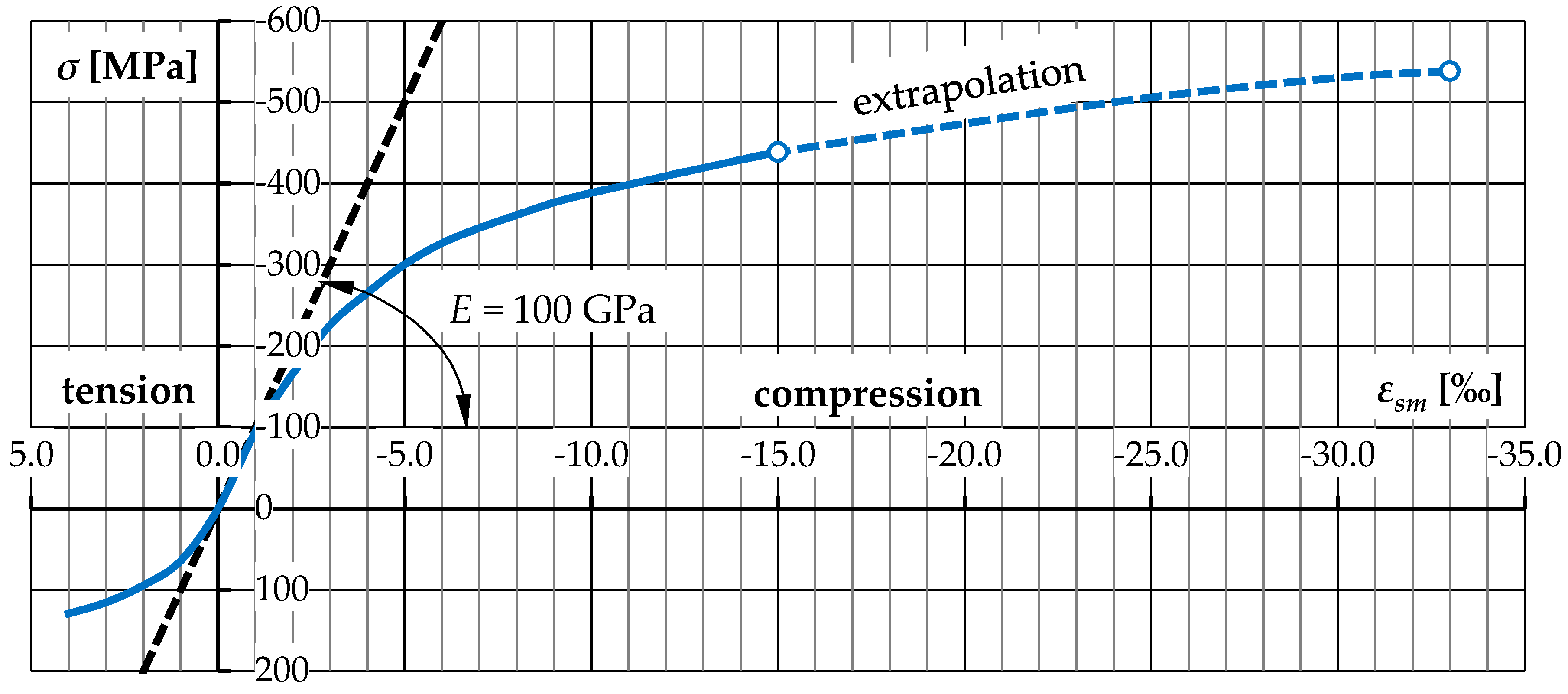
Based on the strain gauge measurements it was possible to determine the exact stress–strain relationship of the tested material—see Figure 13. The deformability of the cast-iron proved to be surprising. The measuring range of the strain gauges ended with a shortening of about 15‰. The section of the curve marked in Figure 13 with a dashed line is an extrapolation of strains up to the ultimate stress calculated according to the maximum applied force. The ultimate shortening could thus be estimated at over 30‰.
2.3. Load-carrying Capacity and Failure Mode
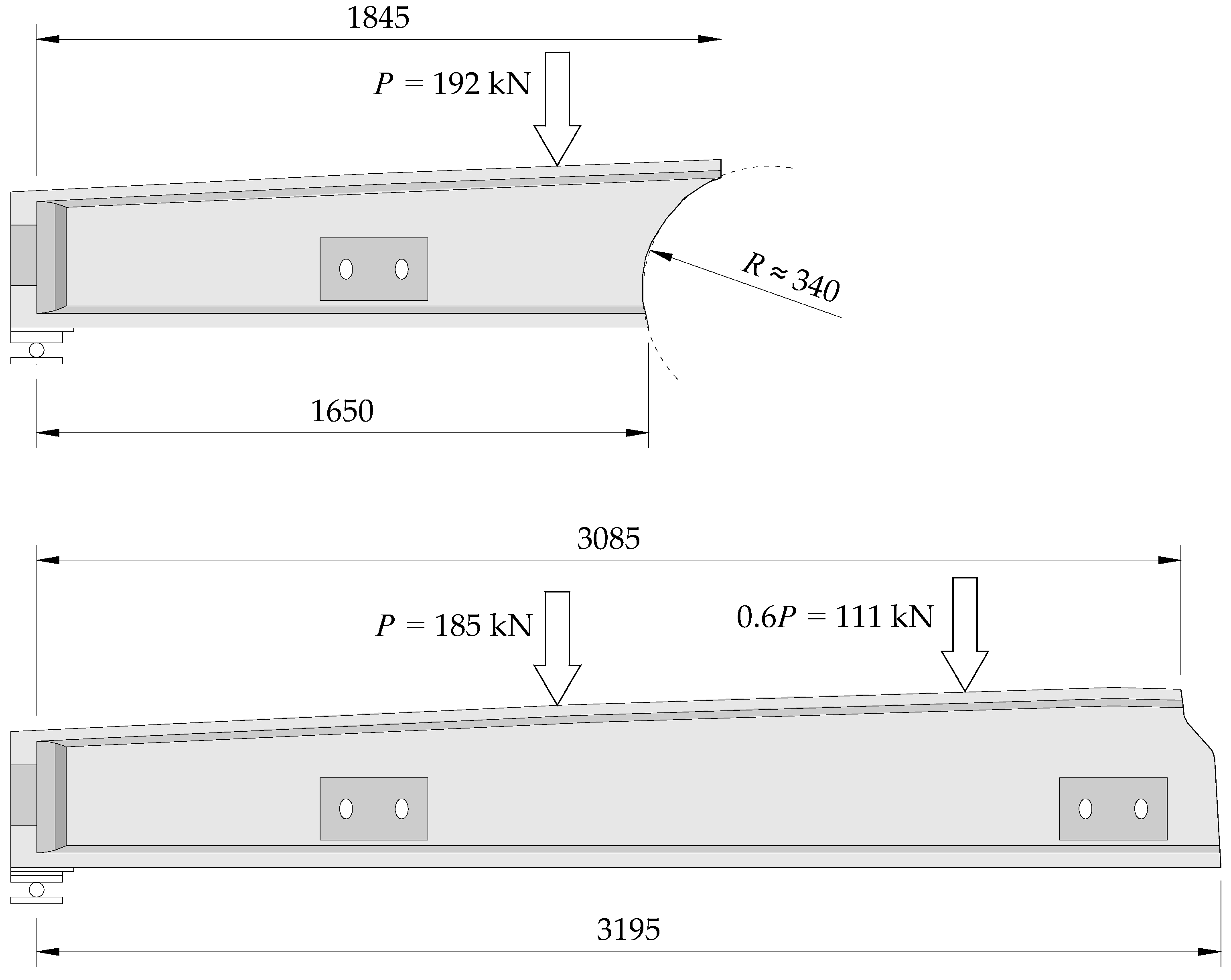
The girders failed in a violent manner, not signalized by a significant increase in deflections, at the forces P equal to 192 and 185 kN. This corresponded to flexural capacities equal to 565 and 544 kNm, respectively. On this basis, an evenly distributed load of approximately 130 kN/m (above the self-weight) was estimated. It corresponded to a characteristic uniformly distributed load of about 40 kN/m2, calculated by assuming a spacing of girders equal to 3.27 m. The flexural resistance of both girders was similar (difference of about 4%) although the critical cross-sections were located at different distance from the support axis (see Figure 14 and Figure 15). This situation is a consequence of the intentional design and manufacture of girders with a variable height of cross-section (curvilinear shape of the upper flange). The shape of the girders was chosen so that the deformations of the upper and lower flanges were similar at most of the central part of the element.
2.4. Strain and Stress Distribution
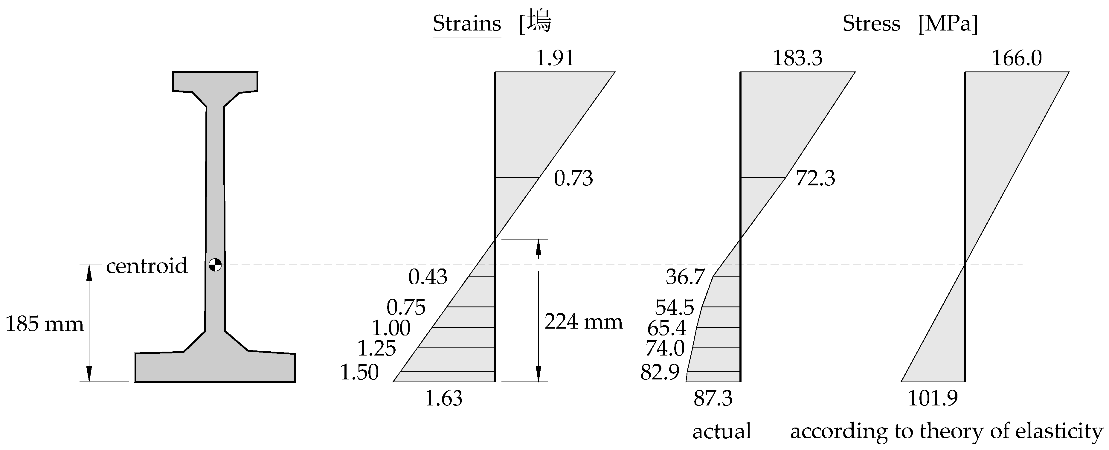
During the tests, measurements of displacements and deformations in the extreme fibers in the characteristic cross-sections of the upper and lower flange were carried out. It was found that the strains on the entire central section of the girder, approximately 1.6 m long, were constant at a given load level, which resulted from the non-prismatic cross-section of the tested element. The maximum deformations recorded immediately before failure were about 1.4 and 1.6‰ (on the tensioned side) and 1.9 and 2.1‰ (on the compressed side). Figure 16 shows the distribution of strain and corresponding stress in the cross-section of the girder at the ultimate force. At the bottom edge ultimate strain of 1.63‰ was recorded, while in the extreme compressed fibre it was 1.91‰. The deformations were determined by assuming the “Euler–Bernoulli” beam theory and then, by using stress–strain relationship (see Figure 13) stress distribution at the girder section was calculated. The middle part of the section maintained in the elastic range, whereas the extreme fibers were already in the range of the non-linear dependence of σ-ε. The point of zeroing the stresses was located above the centre of gravity of the cross-section, which results from exceeding the range of elastic deformations of the material.
It is also important that the tensile strength of the material was not reached at the failure (σmax = 87.3 MPa < Rt = 128 MPa). The stress achieved were only about 68% of the strength obtained in the tensile test. This fact can be explained by inhomogeneity of cast-iron, because on the surface of the girders numerous defects due to the imperfections of the casting process (inclusions and voids) were noticed—see Figure 17.
3. Rehabilitation of the Existing Wooden Elements
3.1. The Idea of Composite Timber and Concrete Floor Slabs
As already mentioned, wooden ceilings were a very popular solution used in buildings erected in the 19th and 20th centuries. In the modernized post-industrial buildings, fire requirements and utility reasons (e.g., the need to increase the load-carrying capacity and the acoustic insulation) very often force the replacement of wooden ceilings with other, contemporary solutions, such as reinforced concrete slab-and-beam floors. Only the outer walls of the old building are left behind. Inside a new load-bearing structure is then made, which can be easily adapted to new needs.
However, if the existing elements are in good technical condition, then it may be advisable to leave the existing wooden beams with the boarding and to make a timber–concrete composite (TCC) floor. Such a solution allows to increase the load-carrying capacity of the existing wooden ceiling even several times [7]. In order to transfer the shear forces arising in the interface zone, it is necessary to introduce additional connectors. In the past, steel nails were used commonly for that purpose, but with large spans of beams and service loads exceeding 2.0 kN/m2, it was necessary to use a lot of them within support zones. Nowadays, system solutions such as special screws, bolts, sheets or meshes embedded in wooden elements [8] are typically used. A significant advantage of casting composite timber-concrete floor slab is a reduction in intrusion into the structure (there is no need to demolish the ceiling above the rooms used), as well as increase of the fire resistance of the ceiling and, above all else, the possibility of leaving historical wooden elements, which is important for conservatorial reasons.
3.2. Examples of the Rehabilitation of the Existing Wooden Ceilings
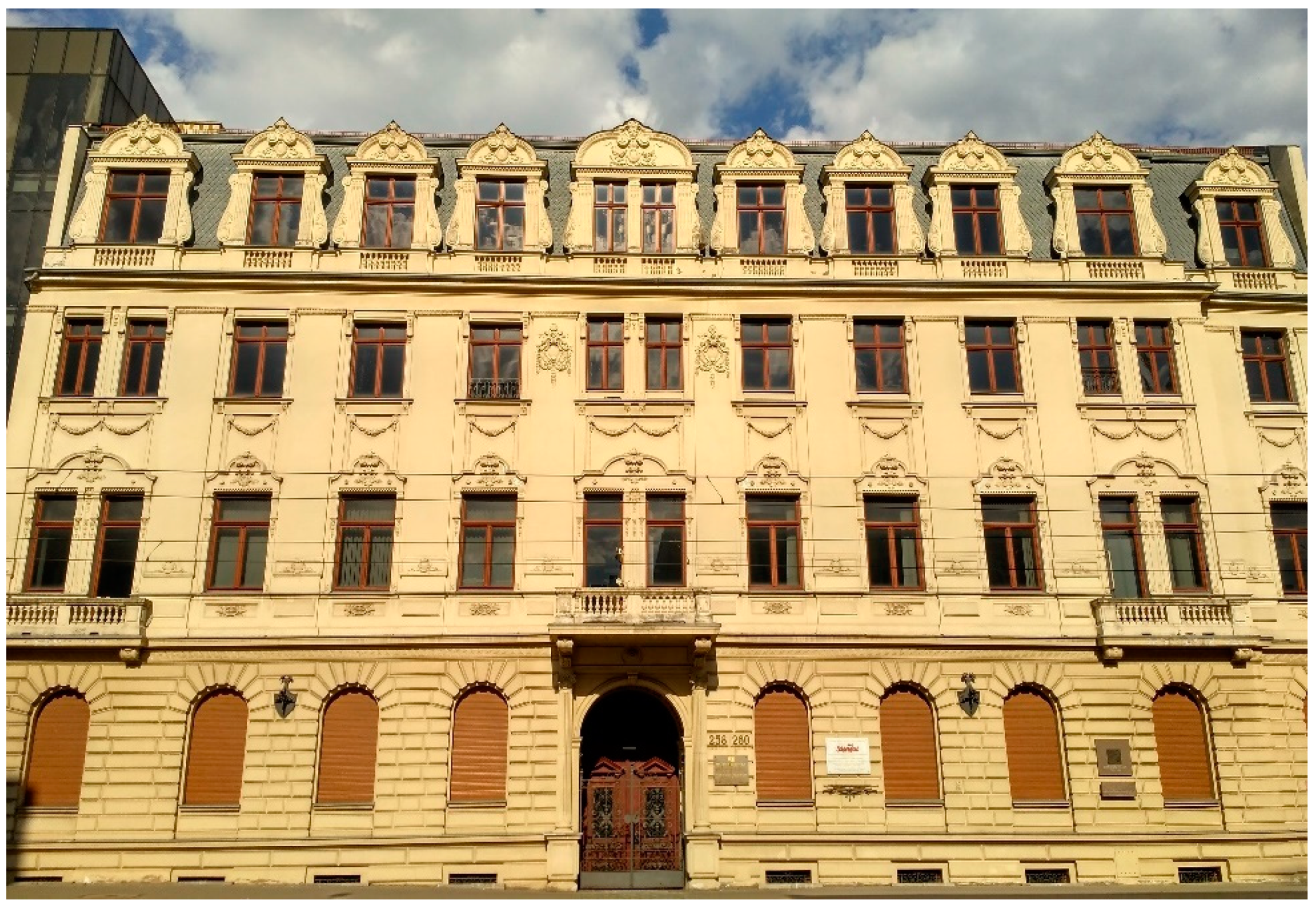
It is worth noting that the concept of composite timber and concrete structures is not a new solution and dates back to the 1930s [9]. At that time, there were the first attempts to use wooden elements in the rib-and-slab floors with ceramic hollow bricks (the “Sperle” ceiling), as well as the use of steel connectors to perform the joining of wooden beams with concrete (connection with iron sheets patented in 1939 by “Otto Schaub”). These solutions were improved in the next decades. In the 1980s at the Lodz University of Technology an alternative method of strengthening wooden ceilings by casting reinforced concrete slabs was developed [10]. This method was later used in many modernized buildings, among others by restoration of the former tenement house of “H. Birnbaum”, who owned a wool spinning mill—see Figure 18.
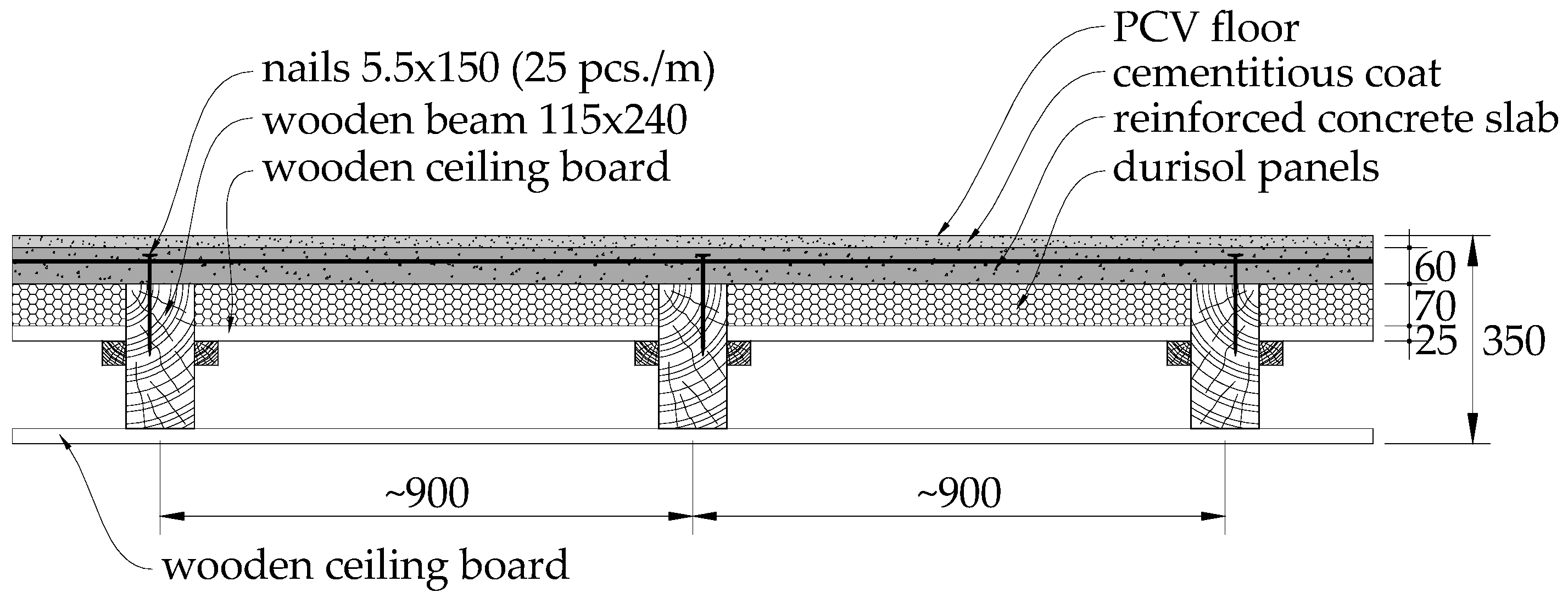
The building was erected in 1893 according to the design of the eminent architect “Gustaw Landau-Gutenteger”. Currently, it houses the Training and Conference Centre of the European Institute. Due to the need to adapt the building to new functions, it was decided to transform the existing wooden ceilings supported on masonry walls into timber–concrete composite ceilings. For acoustic reasons, the previous filling between the beams with pugging was removed and replaced with durisol panels, on which a 60 mm reinforced concrete slab was then casted. The connections of the slab with the existing wooden beams were made with steel nails—see Figure 19.
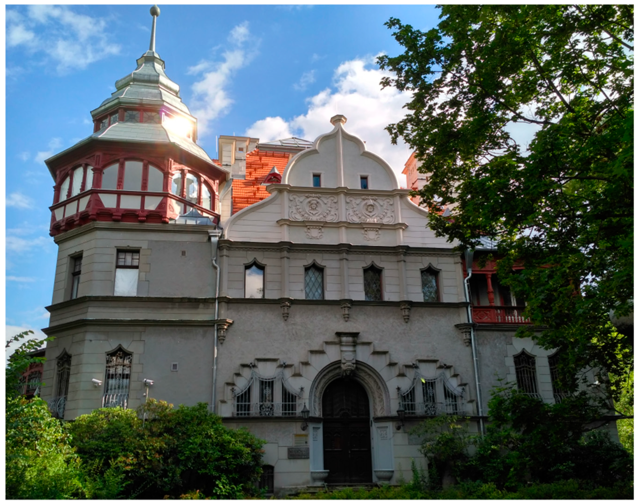
The idea of the composite timber–concrete elements was also used during the reconstruction of the historic “R. Richter” Palace in Łódź, the main office of the Rector of the Lodz University of Technology (LUT). As a result of a fire in 2016, the roof truss, the ceiling above the attic, as well as part of the ceiling joists above the first floor, were damaged. After consultation with the conservation officer, it was decided to introduce a new structural element—a composite timber and reinforced concrete ceiling. This solution was chosen for several reasons. Firstly, it allowed to use the existing, original wooden beams (building preservation maintenance), while increasing the load-carrying capacity of the ceiling (operational conditions). Moreover, the connection of the floor slab with the circumferential tying system enabled to stiffen the walls, which increased their load-carrying capacity. The composite floor created also a fire-resisting division required by the building regulations. Figure 20 shows the building after completion of the first stage of restoration works.
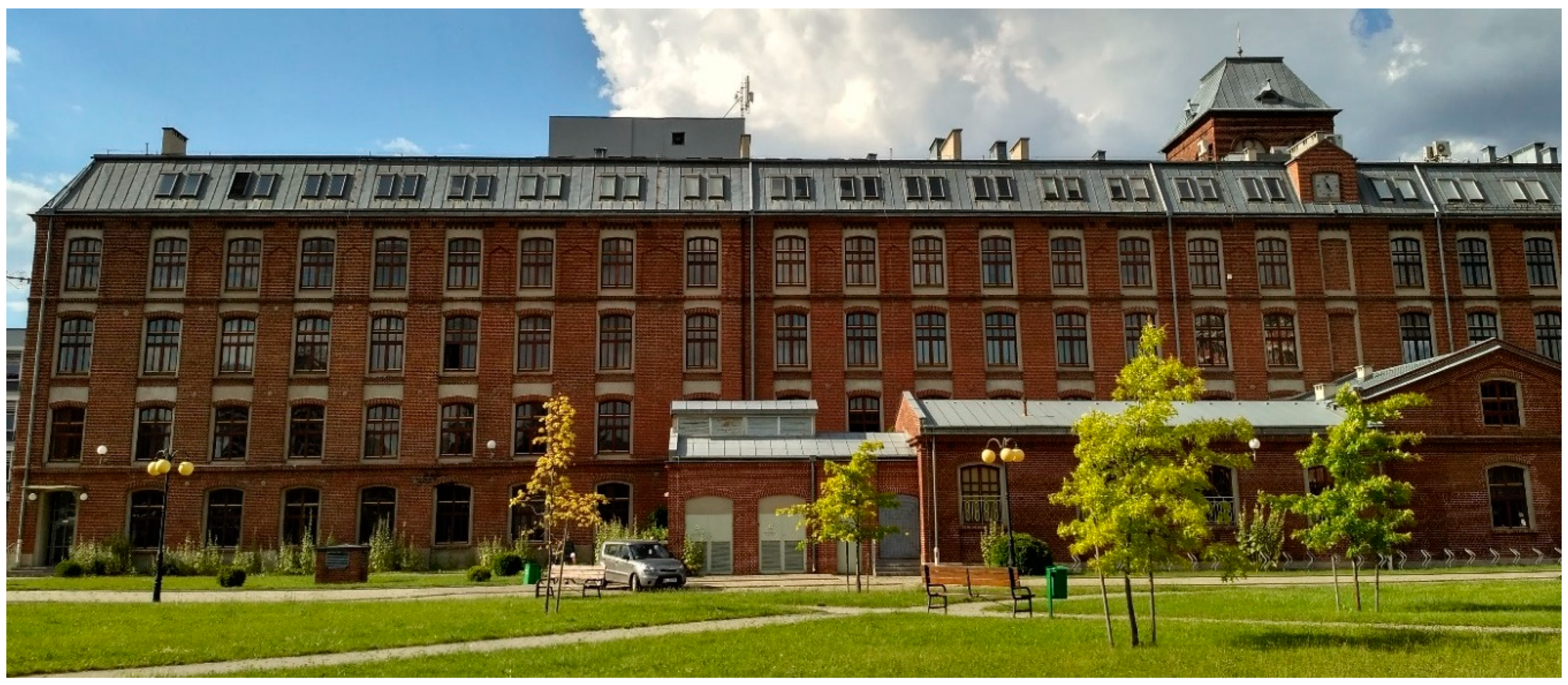
Strengthening the wooden ceilings with reinforced concrete (however with no shear connection) was used by the revitalization of several factory buildings, including the former “F. W. Schweikert” factory. The building was erected in the years 1890–1893 as a factory of woollen products. The structure consisted of external masonry walls with wooden ceilings. Noteworthy is the length of the building, which is over 150 m—see Figure 21.
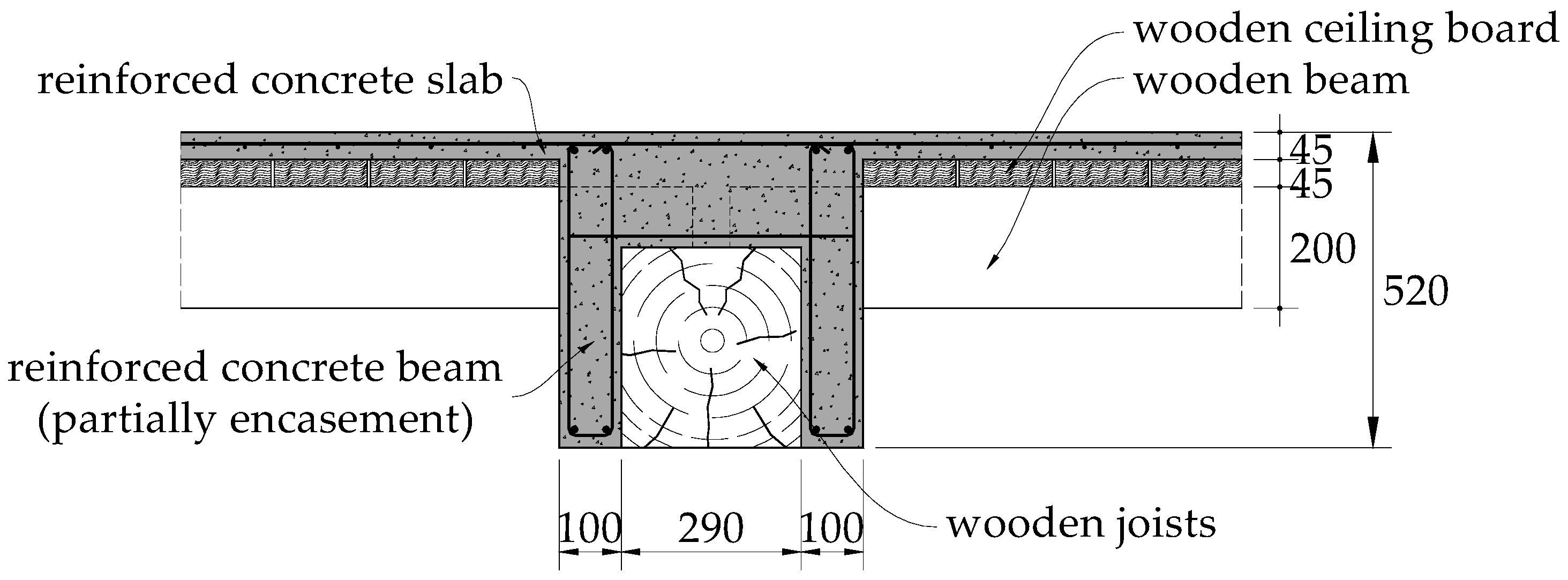
Until the end of the 1990s, the building was used continuously for production purposes. As a result of political transformation, the new owner of the post-industrial complex has become the Lodz University of Technology, which has made efforts to adapt it to new functions—now this building houses three faculties of the university. The change of the purpose forced the adaptation of the structure for new functions. Despite over 100 years of operation, the structure of wooden ceilings in the building turned out to be in good technical condition. Only the beams were characterized by insufficient load-carrying capacity to transfer the increased loads. The designers decided to strengthen them by a partial encasement with reinforced concrete [11], as shown in Figure 22.
4. The Problems Related to Historical Masonry Walls
4.1. Features and Design Recommendations Concerning Mansonry Walls
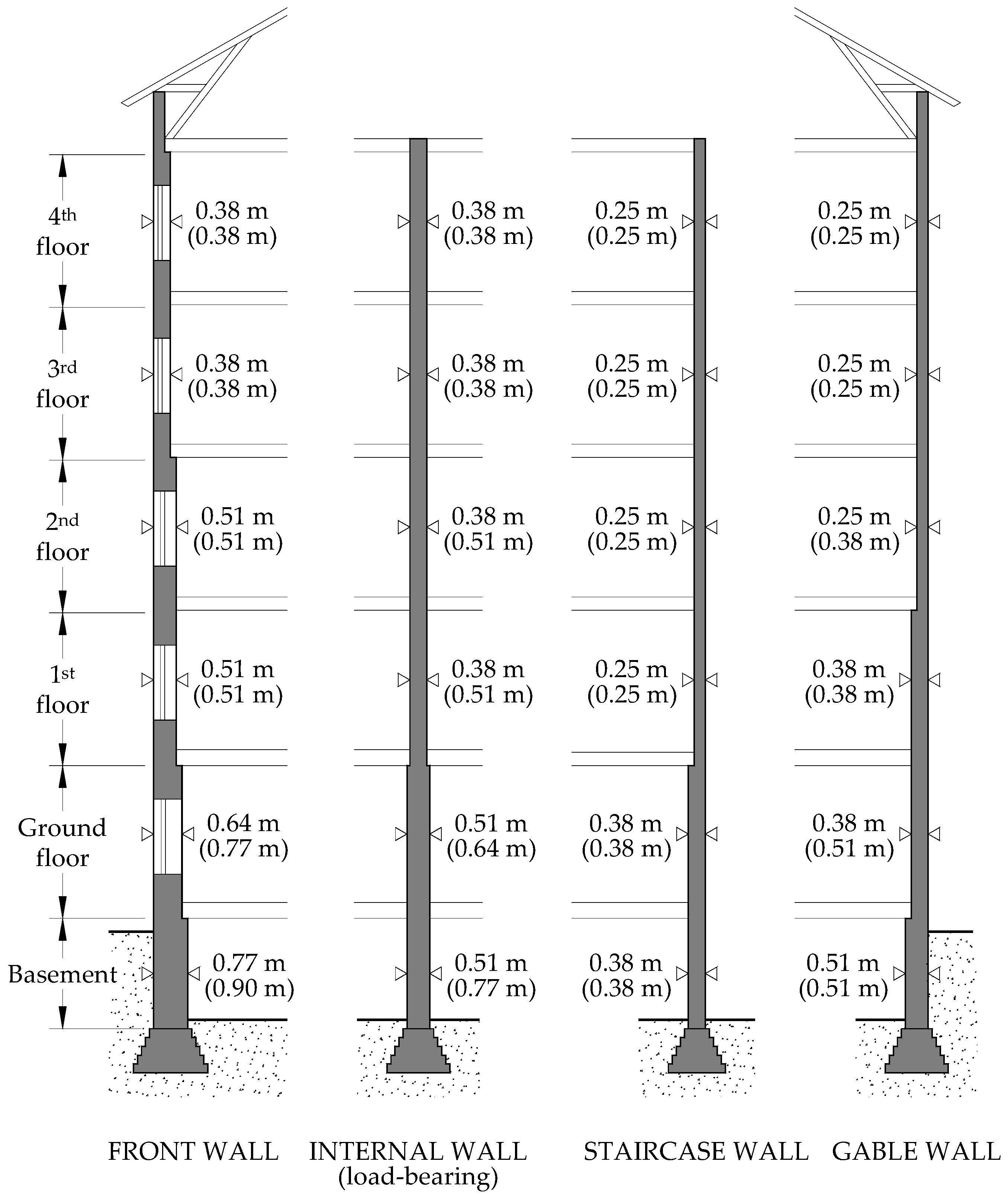
Most of the structural failures that have happened in Łódź in recent years during revitalization, modernization, or reconstruction of the 19th century post-industrial facilities concerned masonry structures. The walls of these buildings were made of solid ceramic bricks bound together by lime mortar. Load-carrying capacity of these walls was not determined by any static calculations. When selecting the wall thickness previous experiences or building regulations (see Figure 23) were rather taken into account. It was assumed that the thickness suggested by the regulations was correlated with the strength of the materials used. From the previous experience, results show that the masonry walls from the second half of the 19th century, and the turn of the 19th and 20th centuries, were made of ceramic bricks with an average strength of 5–6 MPa and were bound with lime mortars with a relatively low strength of less than 1 MPa.
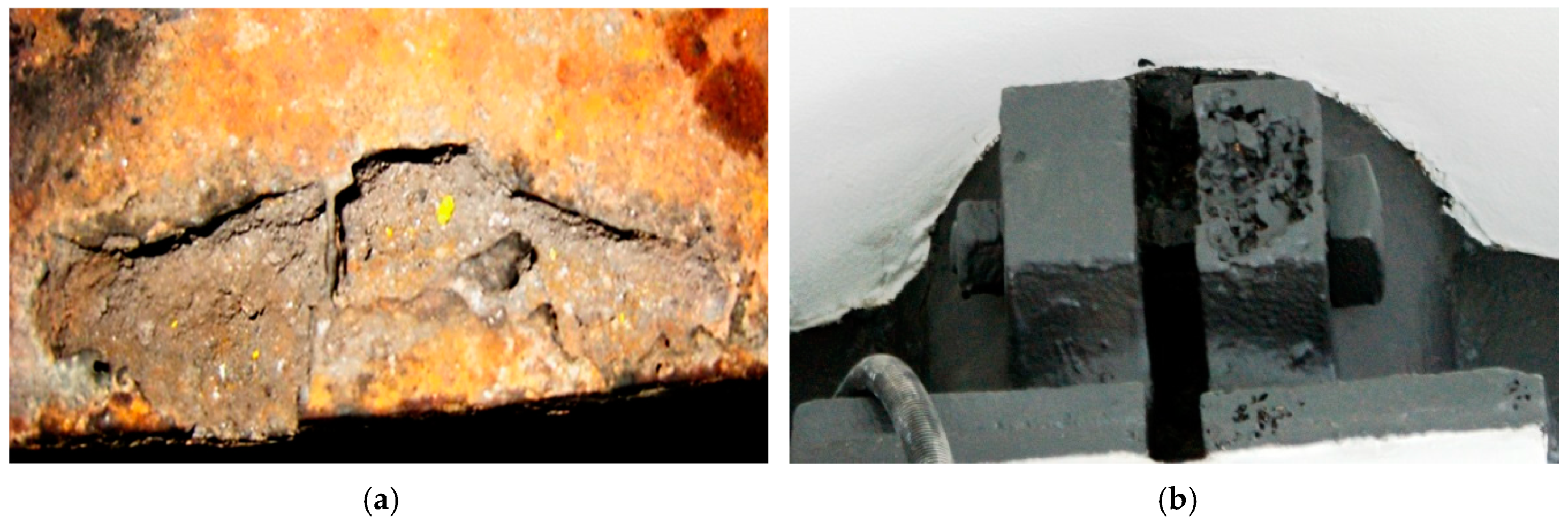
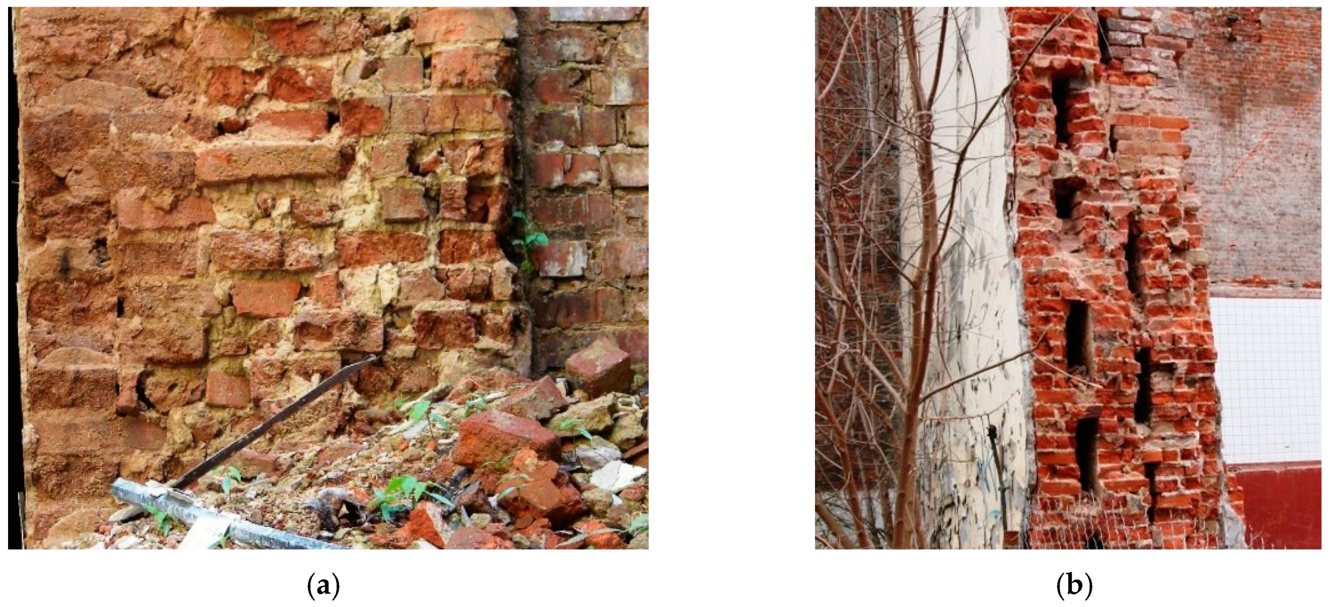
The observations mentioned before should be carefully considered before undertaking any actions related to the historical buildings. Due to low strength of historical bricks and mortar used to connect them (mainly lime mortar), historical walls are characterized by relatively high deformability as well as low compressive strength, which, according to contemporary design regulations, could be estimated as approximately 0.5 MPa. Additionally, the possibility of improper workmanship (Figure 24a) and occurrence of atypical structural solutions that are invisible during visual inspection carried out from the outside (e.g., voids, see Figure 24b) should be taken into account.
4.2. Examples of Failures of the Mansonry Walls
The problem of load-carrying capacity of post-industrial masonry walls is often marginalized, as evidenced by the examples of failures that took place in Łódź in the first decade of the 21st century. One such incident took place in the former “Muller” and “Seidel” factory. As a result of exceeding the load-carrying capacity of the masonry piers in a four-story building, three of them were damaged at the level of the ground floor—see Figure 25.
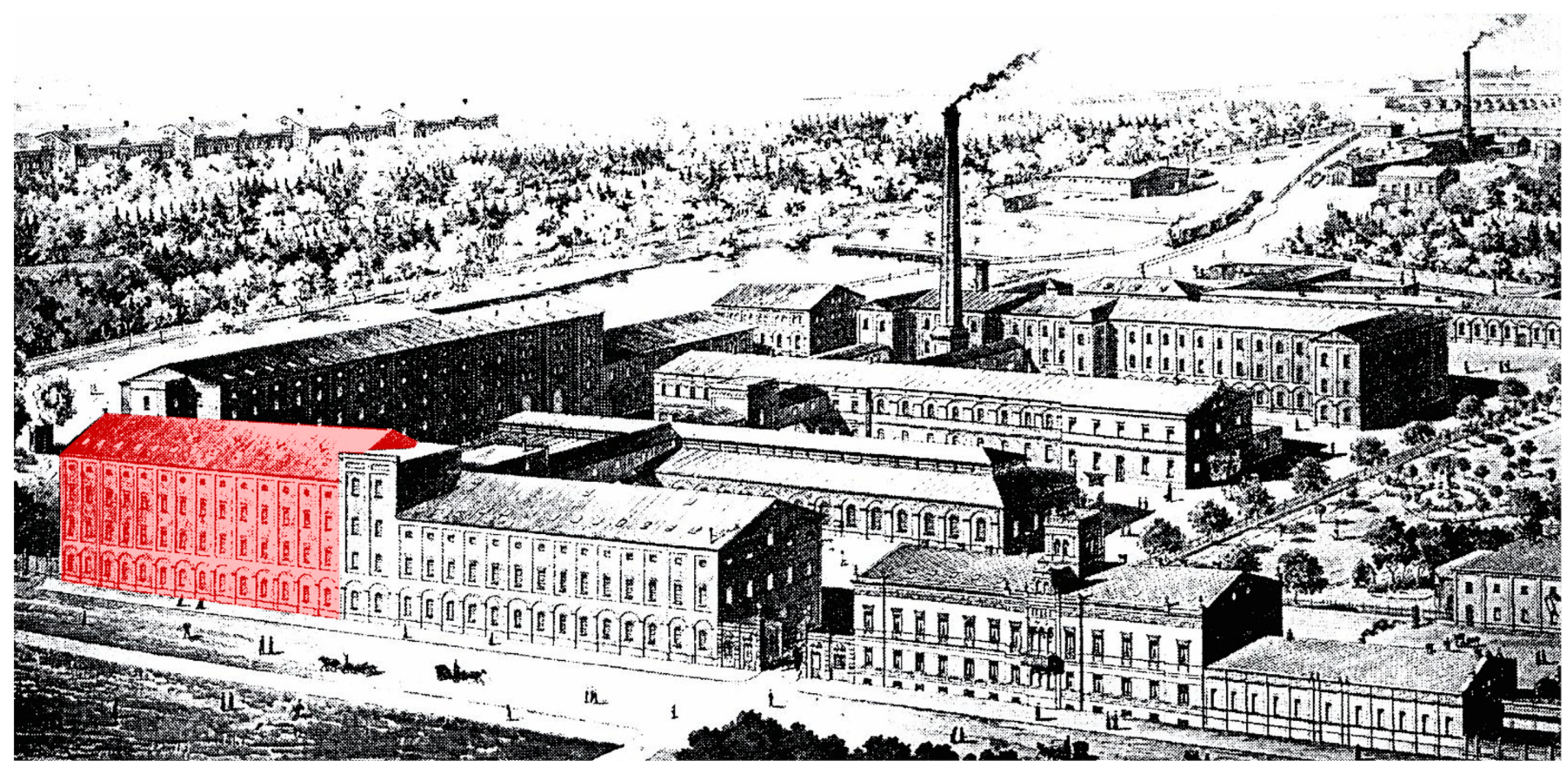
All construction works should be carried out very carefully, even if they do not intrude directly into the structure of the historic building. One of the examples of the tragic modernization of a post-industrial building took place in Łódź [13]. It happened in the former spinning mill, which was built at the beginning of the second half of the 19th century and had a simple geometric shape—see Figure 26 (building marked with red). It was a five-storey building erected on a rectangular plan with dimensions of 150.15×18.80 m. After World War II, the building was adapted to office functions, with rooms located in the external bays and a corridor in the middle section. The main load-bearing elements of the structure were external masonry walls and two rows of cast-iron columns on the ground floor and wooden columns on the remaining floors. Wooden beams were supported on the longitudinal walls and columns. Load-bearing walls were made of solid ceramic brick on lime mortar.
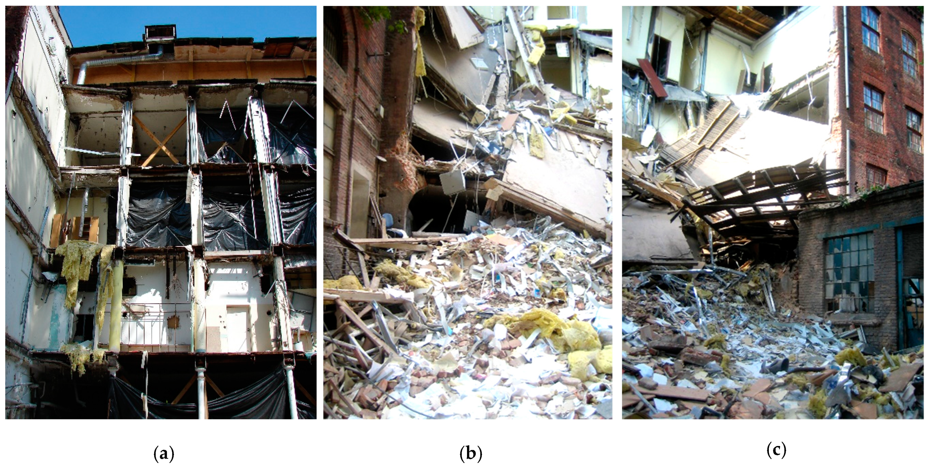
In May 2005, works were carried out inside the building to replace the windows in the southern wall on the ground floor level and cleaning works from the outside of this wall. Heavy equipment (loaders) was used to load the elements remaining after the demolition of the partition walls. The loader operator picked up rubbish while driving perpendicular to the wall. During the works the machine operator was warned about some cracks in the masonry piers between the windows. The works were continued despite the appearance of additional vertical cracks, which were noted by the workers. Soon after, the southern wall collapsed on the section of 5 window openings. Together with the wall, all of the inter-story ceilings collapsed. As a result of the structural failure, two people died, and a dozen were injured. The view of the partially collapsed building is shown in Figure 27.
Due to the negligence committed by the owner of the facility, as well as by the people conducting construction works, it is difficult to pinpoint a clear cause of the event. There was no doubt, however, that the walls of the building erected in the second half of the 19th century were in poor technical condition and did not meet contemporary requirements regarding the load-carrying capacity. The assessment of the wall elements after the disaster showed that the bricks were characterized by a significant change in shape (dimensions). The way the walls were made also left a lot to be desired (see Figure 24a). Laboratory tests showed that the average strength of the bricks was about 5.5 MPa (with a coefficient of variation of 14%), which is a very low value compared to the contemporary ceramic bricks (usually 10–20 MPa). Additionally, the strength of the lime mortar of 0.2–0.8 MPa was significantly lower than the lowest mortar class currently predicted by the standards fm = 1 MPa (for M1 class).
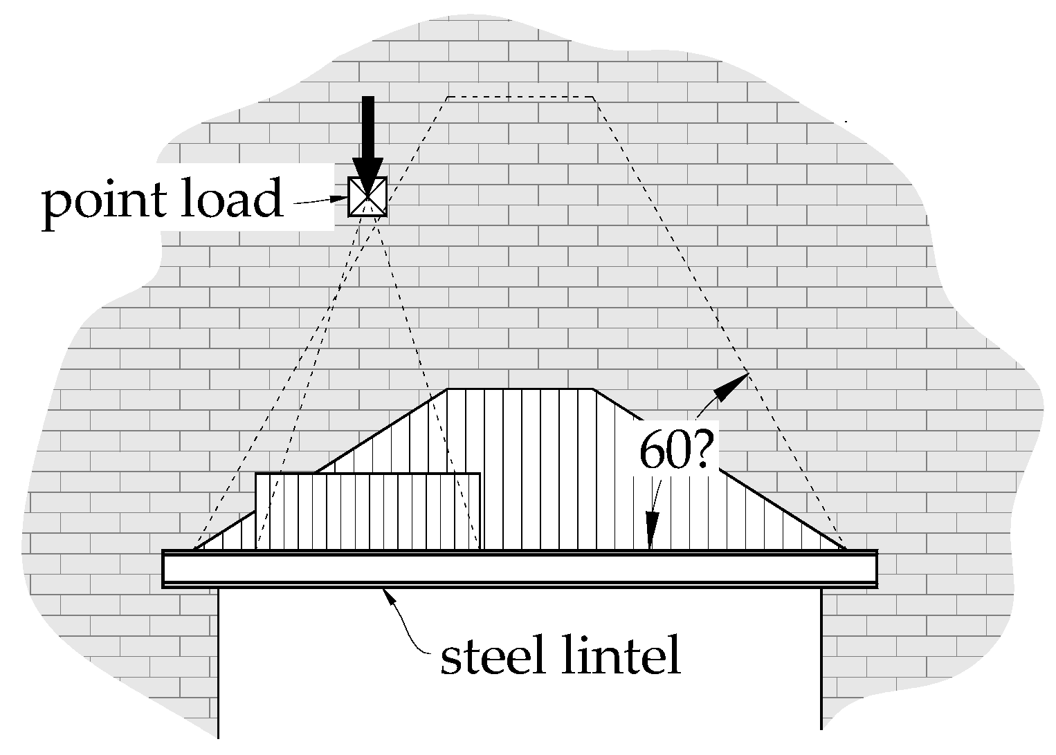
Change in a building utilization very often requires some modifications in its structure. In the case of walls, it is usually associated with the need for additional openings to provide lighting or to ensure communication inside the building. Making new openings requires the introduction of additional lintel elements. For this purpose, steel sections are usually used—C-sections or I-sections, which are embedded in sockets made in the wall. The main purpose of the steel elements is to transfer the self-weight of the wall supported on them, as well as any loads acting above, which is schematically shown in Figure 28. In fact, this simplified approach does not include shear wall effect, which creates an additional safety margin, as the analyses presented by Hardy [14] demonstrated, including that effect may lead to a more economic design of steel lintels, because composite action redistributes the beam load away from the centre. As a consequence, the bending moments are significantly, even several times, reduced, compared to the beam loaded as separate structural element.
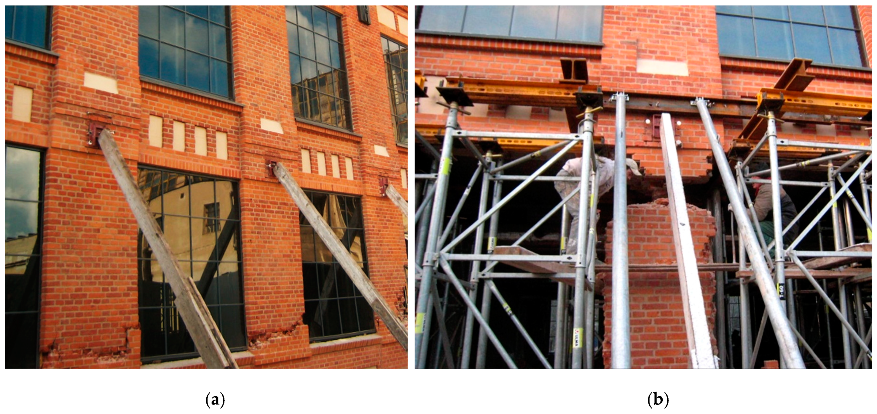
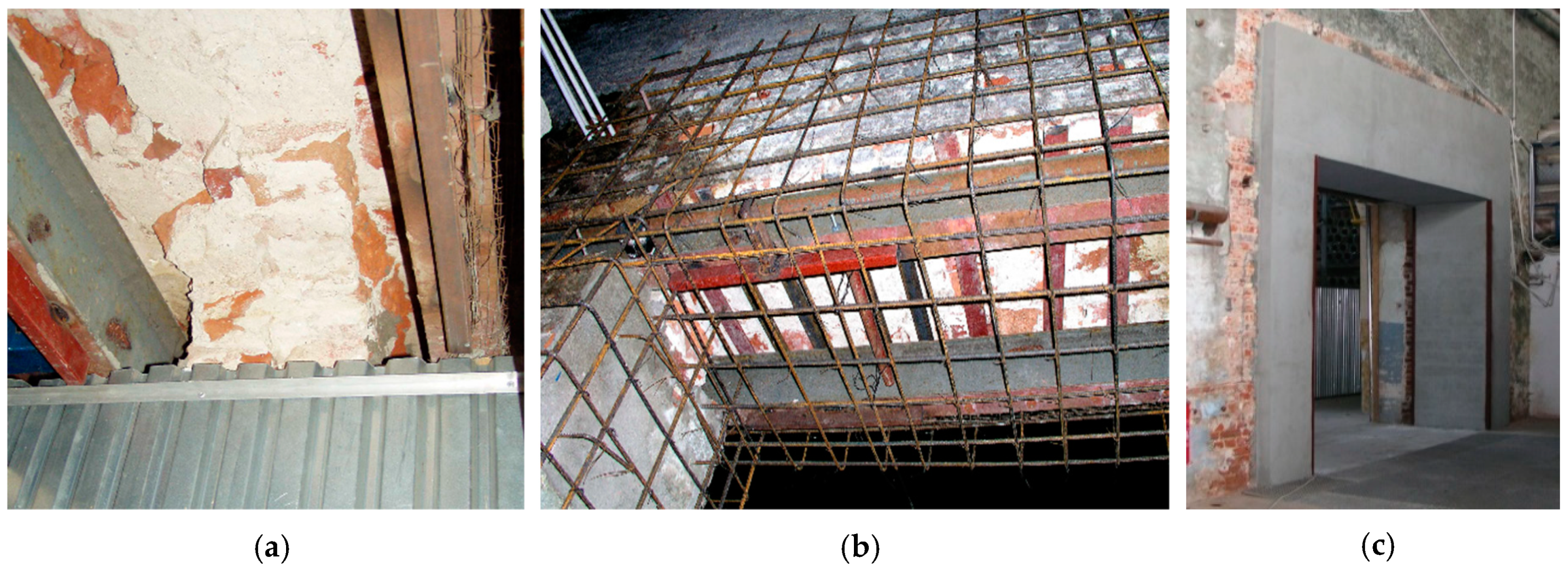
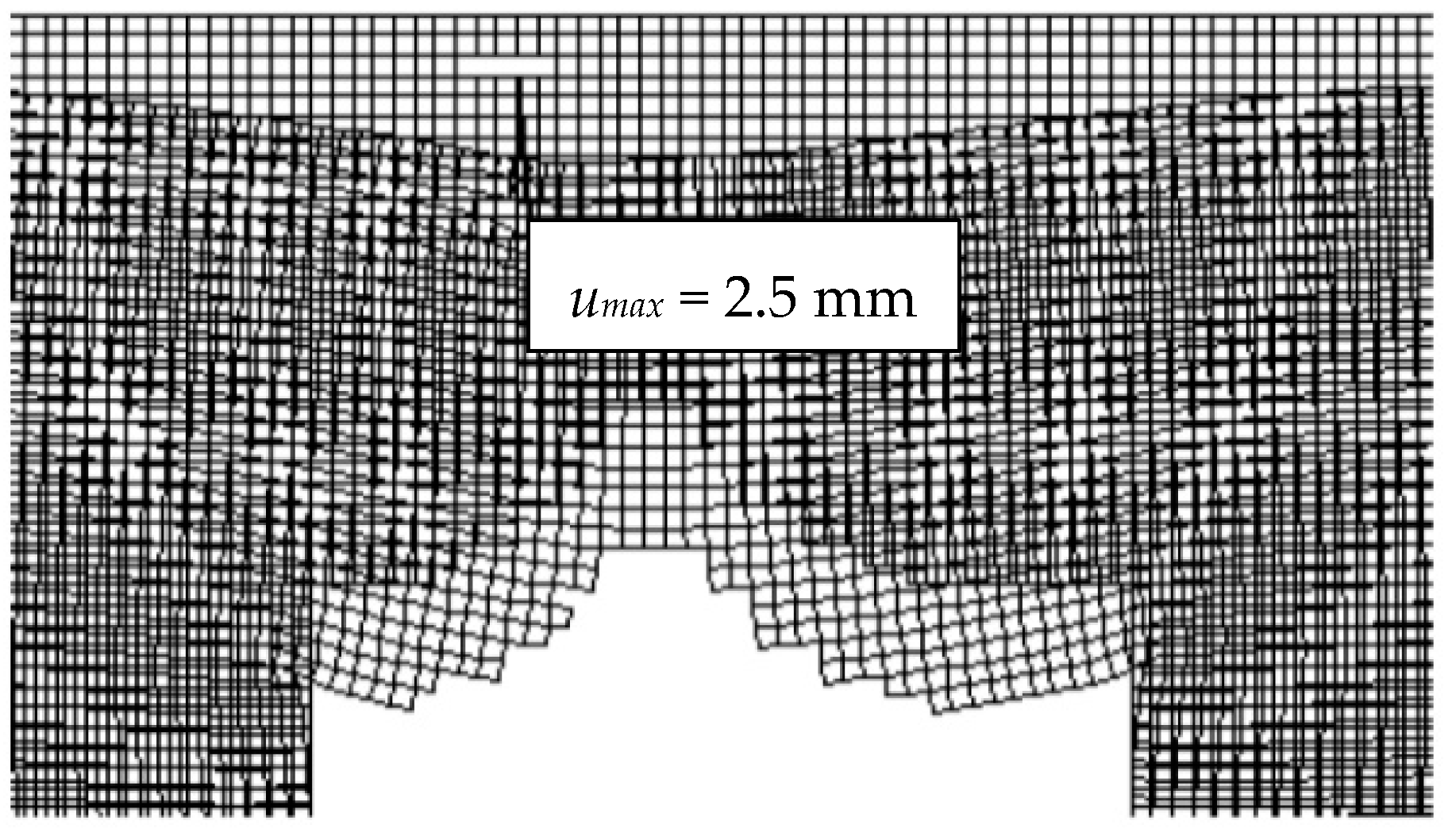
The aforementioned effect prevented the wall collapse in the former boiler house of the “Grohman’s” factory complex in Łódź [15]. As part of the reconstruction works, an opening with dimensions of 3.3 × 4.0 m was made in the load-bearing wall. Two lintel beams of I240-section were introduced as a strengthening element—see Figure 29a. However, the works were carried out extremely carelessly, as the sections were loosely mounted in the wall sockets, which did not protect them against rotation (no anti-torsional stiffening). During the inspection, many loose bricks were found above the steel beams. Several of them became detached, injuring a passing person. Such an accident was, however, inevitable, taking into account the ineffectiveness of steel lintels, high deformability, and very low tensile strength of the wall. In the literature some analytical procedures can be found [16,17], which allow for designing the lintels with including contribution of the masonry wall. In the case under consideration, however, a non-linear analysis was performed. In the Figure 30, the results of the nonlinear analysis for a wall fragment were presented. In the calculations, fracture elements were used, assuming tensile stress above 0.04 MPa as the failure criterion. The formation of a secondary structural system, resembling a vault, is visible, but almost all the elements between the supports failed (detached).
In the presented case, it was decided [15] to strengthen the lintel by making a reinforced concrete portal, joined with the masonry structure—see Figure 29b,c. Despite the difficulties with pouring concrete (due to the limited access to the wall on one side), the work was successfully completed, and it was possible to continue safely use of the building.
5. Conclusions
Examples of the successful revitalization of post-industrial buildings in Łódź provide tangible proof that existing structures can be successfully adapted to new functions. Of course, the revitalization of the 19th century industrial facilities entails many technical problems, which include the difficulty in assessing the actual load-carrying capacity of the structural elements. This is largely due to the lack of certainty about the strength characteristics of the historic materials. In particular, this applies to cast-iron, which due to the imperfections of the former manufacturing process may be characterized by a lack of homogeneity and hidden defects, resulting in a reduction in load-carrying capacity. For this reason, experimental tests are necessary, which, however, require some interference in the construction. Reliable assessment of the condition of historical structures is a guarantee of the success of the entire investment, as evidenced by the example of the “Manufaktura” complex in Łódź.
The example of girders presented in the paper showed that cast-iron elements can often still be safely used despite changing the purpose of the building. At the same time, experimental investigations demonstrated that it can be impossible to fully utilize the strength properties of cast-iron, which is largely due to imperfections formed during casting of the elements. Based on strain measurements, it was shown that the actual stress in the section deviated from the values resulting from the theory of elasticity, which was a consequence of the non-linear stress-strain relationship characterizing cast-iron. Failure of the girders, which was brittle and not signalized by a significant increase in deflections, should be remembered by adapting existing cast-iron elements and determining the allowable load level.
The described examples demonstrated that historical wooden elements can also be successfully used in buildings adapted to new functions. Due to joining the existing beams with the reinforced concrete slab formed on the wooden boarding, it is possible to significantly increase the load-carrying capacity of the ceiling. The effectiveness of such solution is of course strictly dependent on the connection method, but the contemporary system connectors (such as studs, screws, or perforated sheets) make it possible to limit the slip between the slab and the beam, and thus increase the effectiveness of the composition. The application of composite ceilings allows for the preservation of wooden elements of high historical value, which is very important from the legal point of view, as it increases the fire resistance and acoustic insulation of the structure.
Examples of failures of 19th century buildings showed that great care must be taken in all works related to intrusion into masonry walls. It should be remembered that historical walls are characterized by a much lower load-carrying capacity than contemporary ones, which results from lower strength of bricks as well as the lime mortar that bonded them. The quality of the work, which in many cases is low, is also an important factor. The assessment of the existing masonry structures in the light of contemporary design regulations, may thus lead to an overestimation of the actual load-carrying capacity of masonry walls, and thus a failure, as was the case in several of the post-industrial buildings in Łódź.
Author Contributions
Conceptualization, T.U. and M.G.; methodology, T.U. and M.G.; resources, T.U. and M.G.; writing—original draft preparation, T.U. and M.G.; writing—review and editing, M.G.; visualization, M.G.; and supervision, T.U. All authors have read and agreed to the published version of the manuscript.
Funding
This research received no external funding.
Acknowledgments
The authors would like to thank the Reviewers for valuable and helpful comments.
Conflicts of Interest
The authors declare no conflict of interest.
References
- Urban, T.; Gołdyn, M. The Selected Issues of Adaptation of 19th and 20th Century Post-Industrial Buildings in Łódź. In Proceedings of the 8th Euro-American Congress REHABEND, Granada, Spain, 24–27 March 2020. [Google Scholar]
- Addis, B. Building: 3000 Years of Design Engineering and Construction, 1st ed.; Phaidon: London, UK, 2007; 640p. [Google Scholar]
- Czapliński, K. Dawne Wyroby ze Stopów Żelaza (Historical Elements from Iron Alloys), 1st ed.; Dolnośląskie Wydawnictwo Edukacyjne: Wrocław, Poland, 2009; 100p. [Google Scholar]
- DIN 1051. Berechnungsgrundlagen für Gusseisen im Hochbau (Design Principles for Cast-Iron Structural Elements in Buildings); Deutsches Institut für Normung: Berlin, Germany, 1937. [Google Scholar]
- Czkwianianc, A.; Bodzak, P.; Kozicki, J.; Urban, T. Badania niszczące żeliwnych dźwigarów stropowych dawnej przędzalni w Manufakturze w Łodzi (Destructive tests on cast-iron girders of a former spinning mill in Manufaktura in Łódź). Zesz. Nauk. Politech. Łódzkiej 2008, 57, 224–237. [Google Scholar]
- Niezgodziński, M.E.; Niezgodziński, T. Wzory, Wykresy i Tablice Wytrzymałościowe (Equations, Charts and Design Tables), 4th ed.; PWN: Warszawa, Poland, 1984. [Google Scholar]
- Bathon, L.; Bletz-Mühldorfer, O. Ertüchtigung herkömmlicher Holzbalkendecken mit HBV-Systemen (Upgrading conventional wooden beam ceilings with composite timber and concrete systems). In Proceedings of the 8. Europäischer Kongress EBH, Köln, Germany, 21–22 October 2015. [Google Scholar]
- Dias, A.; Schänzlin, J.; Dietsch, P. (Eds.) Design of Timber-Concrete Composite Structures; A state-of-the-art Report by COST Action FP1402/WG 4; Shaker Verlag GmbH: Aachen, Germany, 2018; p. 228. [Google Scholar] [CrossRef]
- Holschemacher, K.; Rug, W.; Pluntke, T.; Sorg, J.; Fischer, F. Holz-Beton-Verbund. In Proceedings of the Holzbauforum, Leipzig, Germany, 10 June 2001; pp. 1–18. [Google Scholar]
- Godycki-Ćwirko, T.; Pawlica, J.; Kleszczewski, J. Verbunddecken aus Holzrippen und Betonplatte (Composite ceilings with timber beams and reinforced concrete slab). Bauingenieur 1984, 59, 477–483. [Google Scholar]
- Czkwianianc, A.; Kamińska, M.; Kozicki, J. Rekonstrukcja drewnianych stropów w przemysłowych budynkach z przełomu XIX i XX wieku (Reconstruction of wooden ceilings in industrial buildings from the turn of the 19th and 20th centuries). Inżynieria i Bud. 2000, 11, 598–600. [Google Scholar]
- Ahnert, R.; Krause, K.H.; Maier, E.; Mönck, W. Typische Baukonstruktionen von 1860 bis 1960 zur Beurteilung der Vorhandenen Bausubstanz, Gründungen, Wände, Decken, Dachtragwerke (Typical Building Solutions from 1860 to 1960 to Assess the Existing Building Structure, Foundations, Walls, Ceilings, Roof Structures), 1st ed.; Bauverlag: Berlin, Germany, 1986; 214p. [Google Scholar]
- Kozicki, J.; Urban, T. Katastrofa budowlana XIX-wiecznego budynku pofabrycznego (Structural failure of a 19th-century post-industrial building). In Proceedings of the XXV Konferencja Naukowo–Techniczna “Awarie Budowlane”, Szczecin–Międzyzdroje, Poland, 21–24 May 2011; pp. 451–458. [Google Scholar]
- Hardy, S.J. Design of steel lintels supporting masonry walls. Eng. Struct. 2000, 22, 597–604. [Google Scholar] [CrossRef]
- Urban, T. Stan awaryjny nadproża w dawnej kotłowni zespołu fabrycznego rodziny Grohmanów (The emergency state of the lintel in the former boiler room of Family Grohman’s Factory complex). In Proceedings of the XXIII Konferencja Naukowo–Techniczna “Awarie Budowlane”, Szczecin–Międzyzdroje, Poland, 23–26 May 2007; pp. 781–788. [Google Scholar]
- Riddington, J.R.; Stafford-Smith, B. Composite method of design for heavily loaded wall-beam structures. Proc. Inst. Civil Eng. 1978, 64, 137–151. [Google Scholar]
- Aloisio, A.; Alaggio, R.; Fragiacomo, M. The architrave a tasselli. Case Stud. Constr. Mater. 2019, 11, 10. [Google Scholar] [CrossRef]
Figure 1.
Wooden frame structure of the Ludwik Geyer’s White Factory in Łódź—1837.

Figure 2.
The structure of warehouse floor in Milford, by William Strutt in 1792–93 (according to [2])
Figure 2.
The structure of warehouse floor in Milford, by William Strutt in 1792–93 (according to [2])

Figure 3.
The fish-belly shape of a cast-iron beam patented by William Jessop in 1789.

Figure 4.
Cross sections of cast-iron beams used in multi-storey factories.

Figure 5.
View of the former M. Silberstein cotton and wool factory.

Figure 6.
Cross-section of the factory building.

Figure 7.
View of the Andel’s Hotel and main entrance to the Manufaktura shopping centre.

Figure 8.
A cast-iron and steel structure of the former Poznański’s spinning mill: (a) during and (b) after the completion of the restoration works.
Figure 8.
A cast-iron and steel structure of the former Poznański’s spinning mill: (a) during and (b) after the completion of the restoration works.

Figure 9.
View of the test setup [5] with: (a) the girder no. 1, (b) the girder no. 2.
Figure 9.
View of the test setup [5] with: (a) the girder no. 1, (b) the girder no. 2.

Figure 10.
Loading scheme in the test [5].
Figure 10.
Loading scheme in the test [5].

Figure 11.
View of cast-iron specimen in the compression test: (a) in the test setup, (b) after failure.
Figure 11.
View of cast-iron specimen in the compression test: (a) in the test setup, (b) after failure.

Figure 12.
Cast-iron specimen after tensile test.

Figure 13.
Stress–strain relationship of the cast-iron from which girders were made.

Figure 14.
View of the girders after failure (location of the critical section was marked).

Figure 15.
View of the critical sections of: (a) the girder no. 1, (b) the girder no. 2.

Figure 16.
Strains and corresponding stress in the section of the tested cast-iron girder.

Figure 17.
Casting defects of the cast-iron girders: (a) gas blowhole, (b) slag inclusion.

Figure 18.
Tenement house of H. Birnbaum—nowadays the office of the European Institute.

Figure 19.
Composite timber and concrete ceiling.

Figure 20.
Reinhold Richter Villa—currently the main office of Rector of the LUT.

Figure 21.
Building of the former factory of Fryderyk Schweikert in Łódź—currently one of the buildings of the Lodz University of Technology.
Figure 21.
Building of the former factory of Fryderyk Schweikert in Łódź—currently one of the buildings of the Lodz University of Technology.

Figure 22.
Strengthening of the existing wooden joists by reinforced concrete encasement.

Figure 23.
Regulations from 1897 concerning required wall thickness in multi-storey buildings, introduced by Berlin authorities (according to [12], values in parentheses apply for factory facilities).
Figure 23.
Regulations from 1897 concerning required wall thickness in multi-storey buildings, introduced by Berlin authorities (according to [12], values in parentheses apply for factory facilities).

Figure 24.
Examples of 19th century masonry walls: (a) careless workmanship, (b) hidden voids.

Figure 25.
View of the masonry piers: (a) after failure, (b) during repair (photographs by J. Kozicki).
Figure 25.
View of the masonry piers: (a) after failure, (b) during repair (photographs by J. Kozicki).

Figure 26.
A general view of the K. Scheibler factory at “Wodny Rynek” at the end of the 19th century.
Figure 26.
A general view of the K. Scheibler factory at “Wodny Rynek” at the end of the 19th century.

Figure 27.
View of the building from the south side after the collapse: (a) remained load-bearing structure (visible cast-iron columns of the longitudinal bay), (b) collapsed inter-story ceilings, (c) collapsed external masonry wall (photographs by J. Kozicki).
Figure 27.
View of the building from the south side after the collapse: (a) remained load-bearing structure (visible cast-iron columns of the longitudinal bay), (b) collapsed inter-story ceilings, (c) collapsed external masonry wall (photographs by J. Kozicki).

Figure 28.
Simplified model for determining the loads acting on the lintel.

Figure 29.
The opening in the masonry wall: (a) emergency condition, (b) during strengthening, and (c) after completion of the repairing works.
Figure 29.
The opening in the masonry wall: (a) emergency condition, (b) during strengthening, and (c) after completion of the repairing works.

Figure 30.
Results of the nonlinear FEM analysis.

© 2020 by the authors. Licensee MDPI, Basel, Switzerland. This article is an open access article distributed under the terms and conditions of the Creative Commons Attribution (CC BY) license (http://creativecommons.org/licenses/by/4.0/).
Share and Cite
MDPI and ACS Style
Urban, T.; Gołdyn, M. The Selected Issues of Adaptation of 19th and 20th Century Post-Industrial Buildings in Łódź. Infrastructures 2020, 5, 69. https://0-doi-org.brum.beds.ac.uk/10.3390/infrastructures5080069
AMA Style
Urban T, Gołdyn M. The Selected Issues of Adaptation of 19th and 20th Century Post-Industrial Buildings in Łódź. Infrastructures. 2020; 5(8):69. https://0-doi-org.brum.beds.ac.uk/10.3390/infrastructures5080069
Chicago/Turabian StyleUrban, Tadeusz, and Michał Gołdyn. 2020. "The Selected Issues of Adaptation of 19th and 20th Century Post-Industrial Buildings in Łódź" Infrastructures 5, no. 8: 69. https://0-doi-org.brum.beds.ac.uk/10.3390/infrastructures5080069