An Internet of Things-Based Low-Power Integrated Beekeeping Safety and Conditions Monitoring System


Laboratory Team of Distributed Microcomputer Systems, Department of Mathematics, University of Ioannina, 45110 Ioannina, Greece
Inventions 2019, 4(3), 52; https://0-doi-org.brum.beds.ac.uk/10.3390/inventions4030052
Submission received: 9 August 2019
/
Revised: 29 August 2019
/
Accepted: 3 September 2019
/
Published: 9 September 2019
(This article belongs to the Special Issue IoT and Energy Internet)
Abstract
:This paper proposes a holistic management and control system for the apiculture industry (Integrated Beekeeping System of holistic Management and Control – IBSMC). This integrated beehive array system mainly focuses on the regulation of bees living conditions, targeting both minimizing bee swarm mortality and maximizing productivity. Within the proposed IBSMC system architecture, additional security functionalities are implemented for bee monitoring, low energy consumption and incidents response. As a complete unit, the proposed IBSMC system is both a hive conditions monitoring and safety system. It communicates with the outer world using low power RF data transmission and the LoRaWAN transceivers. This paper presents the proposed IBSMC architecture consisting of new beehive cells embedded with functionalities for integrated conditions regulation and security provisions, as well as the communication protocols used for facility-conditions management, incidents’ acquisition and incidents’ response.
1. Introduction
The Internet of Things (IoT) industry is shifting at a fast pace towards the agricultural sector, aiming for the vast applicability of new technologies. Existing applications in agriculture are classified into four major fields, which are (i) agricultural environment monitoring and control systems, (ii) open field agriculture systems (Geographical Information Systems), (iii) food supply chain tracking and (iv) livestock monitoring [1,2,3]. This paper is focused on livestock monitoring, proposing the implementation of an IoT management and alert system for modern apiculture.
Artificial beehive cells are used in the beekeeping industry as sites for the establishment of honeybee colonies. The environmental conditions both inside and around the beehives is of major importance to the success of colony establishment and production. An important factor in apiary that affects both colony survival and honey yield is the ability to regulate the beehive temperature [4,5]. Since bee colonies are sensitive to temperature fluctuations, honeybees are actively involved in the thermoregulation of the colony [6], and low temperatures affect the increased mobility of the bees, and thus the reduction of honey yield. Similarly, high humidity levels lead to the production of propolis and wax. As reported both in the literature [4,5,7] and observed by local beekeepers [8,9], in conditions of atmospheric humidity higher than 70%, the beehive requires manual ventilation. So far, beehive ventilation has been dealt with by the use of special ventilation holes on the upper compartment of the beehive cells. This method of ventilation from the top (under the lid on the side walls of the hive) is considered inefficient when the environmental humidity measurements are greater than 90% [9,10]. The moisture reduction mechanisms, employed by the bee colony to prevent the growth of mold within the cells, are mainly based on propolis construction, a rich resinous product with antibiotic, antiviral and antifungal properties. As a result, the bee swarm fills the hive brood box with propolis, therefore limiting the amount of produced honey. In addition, when moisture levels are extremely high, it may lead to underdevelopment and ultimately to the death of bees.
Common practices for temperature regulation in apiculture are still manual in nature, performed by covering the beehives or placing them in sunshade (using insulation materials or blankets for temperature control). Humidity is also manually performed by closing or opening the ventilation holes and hive output hole, or using fans placed at the bottom stand of the brood box.
The proposed Integrated Beekeeping System of holistic Management and Control (IBSMC) system offers both safety as well as conditions monitoring using low power RF data transmissions over a central hive to a cloud-based Information System. Transmitted data include long-range LoRaWAN class A communication via Internet-connected LoRaWAN gateways to the Information System, where collective conditions trends for the beehive array and isolated beehive cells security incidents are stored. These IoT technologies are incorporated into the apiculture, trying to reduce the energy footprint and overcome the energy limitations of existing beehive conditions and safety systems that utilize LTE cellular data transmissions. Furthermore, the proposed IBSMC system’s new beehive cells (described in Section 3) are equipped with new thermo-regulating actuator systems (thermopads, peltier cells), incorporated in the beehive cell brood box. The new beehive cells also include a novel system of natural air flow based on micro-servos for the process of beehive cell moisture extraction, in contrast to existing fan-based solutions. Existing beehive conditions’ monitoring and safety systems are both described in detail in Section 2.
This paper is organized as follows: Section 2 presents existing beehive systems and their capabilities, focusing on beehive arrays security and conditions monitoring. Section 3 presents the system high-level architecture proposed by the author, new beehive cells, central hive and the communication protocols used, as well as services offered. Section 4 presents experimental results and discussion. Finally, Section 5 presents the conclusions.
2. Related Work on Internet of Things (IoT) Beehive Incident Response and Management Systems
IoT Precision Agriculture has been extensively developing and interesting research has been carried out over the last years. Numerous amounts of such IoT systems are currently used (or proposed for use) in apiculture. An interesting survey on IoT management frameworks is presented by Kiani [11], where the architecture of each existing IoT framework is explained. Taxonomy between Software-Defined IoT (SDIoT) and non-Software-Defined Networking (SDN) frameworks is also pinpointed, followed by a comparison of SDIoT and non-SDN-based current frameworks. The pros and cons of each framework are also analyzed.
In the “SmartFarmNet” framework [12], an IoT-based framework is proposed that collects environmental, soil, fertilization, and irrigation data. It concentrates virtually all data from the IoT sensors, actuators, cameras, and weather stations in the cloud. Furthermore, a comparison analysis between IoT cloud platforms such as UBIDOTS, Xively, SensorCloud, IBM Bluemix, Amazon IoT, IoTCloud, Apache Storm and the proposed SmartNet is presented. The advantages of SmartNet is that it supports virtually any IoT device, it provides rapid analysis of data in real-time, it is integrated with Semantic Web and it supports a do-it-yourself visualization and data analysis capability.
Triantafyllou [13] presents the domains and the related applications in the area of IoT, further categorizing all the IoT network technologies in smart cities and agriculture appliance. The features, the characteristics, and the availability of all the known IoT network technologies and routing protocols are analyzed. Furthermore, the networking challenges regarding the security, the interoperability, the identification, the scalability, the big data, the mobility and the energy efficiencies are reviewed.
Ojha [14] outlines the Wireless Sensor Network (WSN) deployments for various farming applications, analyzing the differences between terrestrial and underground WSNs. The usefulness and the potential applications of WSNs in the area of precision agriculture is discussed and comparison between existing sensor platforms and communication technologies is undertaken.
Jayaraman [15] performed an analysis of architectures and communication protocols in the area of precision agriculture. A user-centric model on the design and integration of edge computing, fog communication, and cloud services is proposed. Architectures based on two levels of communications and processing nodes are outlined, and an experimental work based on the proposed architecture is presented, by the use case of a greenhouse.
The most important issues of modern beekeeping involve: 1. Conditions regarding viability, eating habits of the bee swarm, environmental-hive conditions or interventions by external factors and 2. Safety of the beekeeping installation (for both moving and migration apiaries). Both issues are confronted with the use of incident response and management systems that use sensors and actuators operating over IoT infrastructures. In the following sub-sections, existing security and conditions incident response and management systems are presented.
2.1. IoT Beehive Security Systems
Apiary infrastructure safety is the most important concern of the beekeeping industry. Beehive threats can be categorized into three categories: 1. Human theft and intervention, 2. Mammal attacks and 3. Wasp attacks, mites or swarm colony incidents such as queen death, extreme conditions, hunger or even thirst. Security is mainly reported in the literature as human theft or mammal attacks, while wasps, mites, and diseases are chemically confronted [10,16]. The third category of incidents are also considered as condition security threats with no existing incident response system out in the market.
Beekeeping installation safety from animal threats and human theft is an important thread in a migration beekeeping array. However, existing security systems do not offer complete and accurate incident awareness and response security solutions. The most commonly used systems for these types of threats are digital weight scales with GPRS or IEE802.15.4 transponders. These devices provide hive weight measurements and alarm systems if these measurement trends are out of scale [17,18,19,20]. If the beehive’s weight fluctuates above thresholds, beekeepers are notified via SMS, or email or even 3G/4G HTTP push notifications. The weight scale alarm system’s significant drawback is the lack of accuracy, since it requires a flat horizontal base to function correctly, letting the device measurements to fluctuate even on wind blows.
Bee-shop introduced a beehive surveillance camera kit [21], similar to EyeSon [22]. This system camera detects movements and captures photos or records video, sending them to the beekeeper’s mobile phone. The system includes battery pack, SD memory card and requires 3G LTE connectivity. This solution the best safety awareness product presented in the market that can also respond to condition security threats. Nevertheless, it introduces significant energy consumption and fast battery depletion triggered by false motion detection alerts. For static and moving apiaries, electric fence installments around the beehives are also used. However, such solutions do not offer effective human theft protection functionality.
APISAFE [23] and other similar market products such as Beebot [24], Hive-Tech [25] and HiveMind [17], and Arnia system [26], apart from hive conditions monitoring (temperature, humidity and environmental readings), recommend an alternative mechanism for keeping beehives safe, similar to the mechanism used by fleet management systems. That is, GPS anti-theft tracking devices. Beekeepers immediately get notified during the conduct of beehive theft incidents. The device provides continuous post-theft tracking by sending GPS coordinates over 3G or SMS (using 1–5 min periodic intervals of GPS location changes) for precise mapping of the thief’s location. The battery autonomy of these systems is advertised as 2–3 months but has been experimentally measured by authors to operate successfully for no more than 25 days for a 10,000 mAh battery, for 1 min periodic GPS measurements transmission. Moreover, such systems are safe and harmless for the bees. GPS anti-theft tracking devices have been proven as not a good method for keeping beehives safe, due to their high complete deployment cost to a beehive array. GPS tracking devices are alternatively used in one or two hives per array and if spotted by thieves can be easily neutralized without an alert feedback. In case of animal attacks, GPS tracking devices do not offer significant protection, since animals only cup side or break the beehives, without moving them around. Furthermore, GPS transponders do not have the granularity to detect small movements (less than 6 m) and trigger alerts accordingly.
2.2. IoT Beehive Conditions Monitoring Systems
Focusing on the beehive industry conditions monitoring systems, a number of them have already been proposed and are commercially available: Beebot [24], Hive-Tech [25], HiveMind [17], EyeSon [22], Arnia system [26], B-ware system [19] and BuzzBox [27]. Most of them monitor the environmental conditions inside and outside the beehive. The conditions that are often sensed are temperature, humidity, luminosity inside and outside the hive, as well as micro-climate environmental conditions including readings of rainfall, wind speed and atmospheric pressure [28]. In addition, there are no known systems in the literature that can diagnose diseases and bee illnesses, such as varroa mites and produce alerts. Having sensory input with the help of data mining – A.I. algorithms, the above systems offer indirect decisions about hive status, honey productivity, feeding requirements, queen vitality, colony size reduction, and disease insurgence. In the following paragraphs, the most reliable IoT systems and the IoT technologies used are outlined.
The B-ware system [19] monitors a beehive’s precise weight and ambient temperature. It is placed under each beehive and continuously sends data to a Monitoring System via a local Data Collector. The system supports up to 100 hives with a maximum distance of 50 m between the hive’s local Data Collector. The data are sent through Bluetooth Low Energy (BLE) [29]. A solar panel provides adequate energy to the local Data Collector.
The Arnia remote hive monitoring system [26] is another conditions management system that monitors brood temperature, hive humidity, temperature, acoustics and vibration. CO2 measurements and meteorological data, such as rainfall, temperature and sunshine, are also gathered. All the data collected from the hives’ sensors are transferred wirelessly to a local getaway, which sends the data to a cloud service for processing and presentation on user interfaces.
The Hivemind monitoring system [17] reports the in-hive humidity, the inside and outside temperature, the number of bees entering or leaving the hive, and the weight of the hive, as well as rainfall and GPS location. All the data from nearby beehive sensors are gathered to a hub concentrator device which forwards the data to a cloud service.
Another bee monitor system is EyeSon [22]. It uses a camera and computer to visually monitor bee activity and measures the number of flying bees, tracking their flight behavior. Colony activity patterns are tracked over time by using computerized video analysis. EyeSon provides video playback and alerts through an appropriate web application.
The BuzzBox beehive monitoring system [27] is another IoT monitoring system that records indoor and outdoor temperature and humidity, pressure, GPS location, wind speed and direction and acoustics. It transfers data to a cloud service from a local-area Wi-Fi access point.
Hive-Tech [25] is also a beehive management system that constantly monitors the hive’s sound, temperature, humidity, weight and scents. The GPS position, the intensity and the spectrum of the ambient light, quality of air, oxygen and carbon dioxide are also monitored. Post-processing of this data produces information about productivity, brood, queen vitality, imminent swarming, stocked honey, and disease insurgence. The recorded data are transmitted to the cloud via Bluetooth or the GSM network.
The remote beehive management system Beebot [24] also gathers vital information about temperature, humidity, acoustics and weight changes of the beehive. Data are sent to the cloud via the Wi-Fi network where processing gives information about the health and the productivity of the bee colonies.
All of the above IoT systems transfer their data to the local wireless gateway via 2.4 GHz Wi-Fi or Bluetooth Low Energy (BLE) [29]. The proposed IBSMC system architecture described in the following section is a novel IoT incident response system that includes the most critical temperature and humidity condition IoT sensors as well as active hive management mechanisms (IoT actuators and automated processes) for the process of humidity and temperature regulation in critical condition events. Furthermore, the proposed IBSMC system makes use of the Low Power Wide Area (LPWA) networking protocol LoRaWAN [30]. This protocol is capable of wide range coverage of up to 12 km away from the hives, for the process of data transmission in the free ISM RF band of 868 MHz.
The IBSMC low energy data transmissions and low-cost system sensors and actuators enables the ability of automated extreme conditions interventions coupled with a robust safety and incident reporting mechanism for all types of safety incidents. The proposed capability of detecting beehive condition changes and reaction is performed with the use of low-cost and low energy consumption actuators deployed in all beehive cells. Furthermore, data transmissions are performed in the ISM band without unnecessary LTE provider costs for the beekeeper. Table 1 shows the existing systems’ capabilities regarding safety and conditions monitoring as well as the advantages of the proposed IBSMC system with respect to existing ones.
3. Proposed Integrated Beekeeping Active Management and Conditions Control System (IBSMC) System Architecture
The proposed system is an integrated automated beekeeping control, management and safety system for the apiary (Integrated Beekeeping active Management and conditions Control System, or IBSMC). The system architecture is illustrated in Figure 1. The proposed system consisting of subsystems are as follows:
- For the process of monitoring beehive conditions and security incidents, a new type of automated beehive cell has been implemented on top of Langstroth-type plastic hives. This new type of automated beehives includes the built-in sensors and actuators presented in Figure 2a–c.
- A central point for data collection of the automated beehives, placed inside the beehive array, is named the central hive (Figure 2d). The automated beehive cells transmit their data to the central hive, using wireless low power, low throughput, and short distance RF technologies [31,32], described in the communication protocols section that follows. The central hive is responsible for recording sensory data, forwarding incidents from the other automated beehives, as well as performing per beehive actuator control based on environmental conditions. Data transmissions, notifications forwarding between the central hive and the cloud information system, is performed using the chirp spread spectrum LoRaWAN class-A specification [33] for long-range low-power communications. That is, transmitted data is stored to intermediate LoRaWAN gateways [34] prior to submission to the appropriate cloud data logging service via MQTT. LoWaRAN gateways are the IoT IBSMC system backbones and have to be installed and maintained throughout the area of interest or the beekeeping migration areas. The LoRaWAN gateways are placed in locations of uninterruptible power supply and Internet connectivity. LoRaWAN gateways are responsible for the beehive arrays authentication and data forwarding to the appropriate IBSMC cloud service. LoRaWAN mechanisms such as over the air activation (OTAA), statically set AES-128 app-key join authentication, payload encryption and adaptive data rates functionality (ADR) [35,36], have been preferred over custom LoRa-based protocols, due to easy to maintain implementations and scalability features [35,37]. Furthermore, LoRaWAN presents higher probability of success over distance, less jitter and at least 20–50 times less energy consumption in comparison to IEEE802.15.4 and ZigBee devices already used in many IoT paradigms [34,36,38,39]. Regarding IoT data security in LoRaWAN OTAA mode, symmetric encryption AES-128 is used. The devices motes themselves generate and exchange with the LoRa server, the network session, and application session keys during the OTAA join request phase, using an AES-128 commonly shared application key stored both at the LoRaWAN server and motes. The integrity of those key exchange messages is assured with an AES 128-CMAC process (MIC generation) that includes devEUI values, a frame counter value and a nonce value. Data encryption between automated beehive cells and the central hive is performed with the use of an AES-128 symmetric encryption algorithm and a common node pre-shared encryption key for all the beehive array cells. The usage of a static encryption key can be replaced in the future with a more adaptive authentication and key exchange mechanism similar to that in reference [40]. Furthermore, AES-128 data encryption delays can be improved with a more efficient symmetric encryption algorithm, such as Twofish for IoT implementation, as mentioned in reference [41], or TEA(XXTEA), as implemented for IoT devices by the authors in reference [42].
- A cloud-based Information System for Management and Control of Apiaries (ISMCA) is offering cloud services for logging of conditions (logging service) and store-forward of notifications-alerts (push notifications service) of beehive arrays. These services exchange data over TCP/UDP-based communication protocols with the beekeeping arrays LoRaWAN gateways. That is, MQTT/TCP protocol [43] is used as the transport medium for sensory data by the gateways, and CoAP/UDP protocol [44] for the data transmission of control signaling to the beehives, from the server to the central hive via the gateways. Both protocols have been selected for their IoT performance characteristics in terms of asynchronous functionality and low throughput footprint [45,46]. ISMCA systems also implement a LoRaWAN server functionality [33,34] for the purpose of authenticating gateways and nodes of each beekeeping arrays central hives, responsible for the cloud data exchange of each array. The Over-The-Air-Activation (OTAA) method is used for LoRaWAN node joins. In this join process, a 64 bit device identification (ID) (DevEUI) and a unique per application 64 bit application ID (AppEUI) statically set at the LoRaWAN server are used for node-to-server authentication. The data generated from this authentication join process network and application session keys are then used for AES-128 payload encryption and construction of the Message Integrity Code (MIC) in each LoRaWAN transmitted frames’ payload [30,33]. However, since the initial join request message fields are plaintext transmitted, the whole authentication process is susceptible to replay attacks since the DevNonce join request value can be easily predicted. A more robust and adaptive authentication mechanism using a PKI infrastructure [40] is by far more robust and is considered as future work, but the usage of a non-symmetric algorithm for the process of IBSMC data encryption contributes significantly to the end motes energy consumption by increasing significantly transmitted data payload sizes [41].
- Collective information from a specific beekeeping array as well as notifications via the cloud push notification service are presented to the bee farmer via a user-friendly mobile phone application that interacts with the Information System for Management and Control of Apiaries (IMSCA) system services. The management module of the proposed ISMCA system cloud services provides specific capabilities to the apiarist, such as: a) automated information services monitoring the status of the beehives and beehive array events, b) monitoring of the beehives using sensors and supervision services with alerts, notifications and forecasts, and c) recording of the beekeeper’s apicultural interventions within the beehive array (regarding nutrition cases or disease events). The IBSMC system will also provide specific cultivation suggestions in order to produce higher quality products and modeling capabilities that focus on the formation of cultivation partnerships and for creation of recognized brand products.
3.1. New Beehive Cells Supporting the IBSMC Architecture
Functionality of the IBSMC system requires the use of new beehive cells or modifications to existing ones. This paper proposes the design and implementation of new, automated beehives with built-in, low-power consumption control actuators, and built-in safety sensors. In particular, the temperature-humidity conditions affecting the bee colony can be divided into two distinct cases [6,8,9]:
Low temperatures: below 10 °C. The precise lowest temperature value for the bee colony has not been determined in the literature as it varies considerably across region and breed. However, occurrences of group deaths have been reported for honeybees inhabiting the coldest parts of a hive. An apiculturist inspecting the hive can therefore be faced with groups of dead bees that had consumed all the honey from the cells on that side but were probably weakened and incapable to move to the other side of the hive, where honey may still be intact. Low temperatures combined with increased humidity are set to be the most destructive conditions that combine both high mobility and increased propolis content.
High temperatures: In environmental temperatures of above 32 °C (up to 38 °C), it has been observed that honeybees are not significantly affected, since hives are positioned in shady places, near water deposits. Beekeepers would typically use 10–50 liters of open water containers for cooling the bees during the hot summer days. Apart from temperature, humidity also plays a critical factor for the water deposition required. Temperature measurements inside and outside the hive in conjunction with the application of appropriate data mining and prediction algorithms would enable the beekeeper to create a time-plan for water deposition. In addition, daytime sunshine and heat intensity monitoring can enable the beekeeper to place the hives in the most suitable and shady places (e.g., in a storage area) during the summer and move them to the brightest areas in the winter.
Using automatic ventilation coupled with a heat-cool comfort sub-system to replace the static, manual hive thermoregulation operations would simplify apiculture practices and more efficiently handle the conditions inside the hive. Furthermore, it would protect the apiary from outbursts of severe environmental conditions that are difficult to circumvent in time by manual interventions.
The proposed new beehive arrays are presented in Figure 2 and consist of the following condition monitoring sensors-actuators:
- A thermo-pad cells actuator unit for providing thermal comfort, if required. In the back side of the hive box, a 5V heated thermo-pad surface is placed, responsible for providing heat comfort inside the beehive (Figure 2a (5)). It is isolated from the bees with the use of a plastic PVC surface with 1 mm apertures so as to assist heat flow in the hive. The thermo-pad actuator unit is controlled by the beehive MCU (Figure 2c (3)) and it automatically powers up and resumes its last operational state at low temperatures (less than 0 °C). The specified maximum operational time interval for the subsystem is 3.2 h per day to avoid battery depletion, spread out uniformly (8 min per hour) using PWM control. The on interval of the subsystem can be set to 0, 2, 4 and 8 s per minute (disabled, low, middle, high). The operational state of the subsystem can also be remotely controlled by the central hive. Its current drain is at 750–1000 mA, thus giving a maximum daily energy consumption of 3 Ah and a minimum of 0.8 Ah depending on the operational state.
- Peltier cells actuator unit provides cool comfort. The six peltier modules (Figure 2c (6)) are mounted on a 3 mm transparent PVC surface with their cool surface aiming at the internal hive and their hot surface aiming at the hive’s lid. When the peltier actuator is powered up, it removes heat from the internal hive towards the hive lid. For the heat extraction process out of the hive, the peltier unit also uses a 5V DC external heat blower installed onto one of the hive’s ventilation holes (Figure 2c (9)). The peltier actuator subsystem is controlled by the beehive MCU (Figure 2c (3)) and it can be remotely powered up or down only at high temperatures (more than 36 °C). The specified maximum daily operational time interval for the subsystem is 48 min to avoid battery depletion (2 min per hour). The “on” interval of the subsystem can be set to off and PWM settings, giving an 8 s “on” interval per 4 min period, depending on the subsystem operational state (disabled, enabled). The operational state of the subsystem can also be remotely controlled by the central hive. Its current drain is at 2600 mA including the blower, giving a daily energy consumption of around 2 Ah.
- The fan actuator unit focuses on moisture removal. This unit consists of three DC micro-servo motors attached in the upper part of the three remaining lid ventilation holes. The servo motors are mounted on a lightweight insulation surface and maintain a plastic arm (Figure 2b (1)). The servo motors can move in controlled angles of 0°, 45°, 90°, 120° or be set to continuous shifting (0°–120°) over a 5 s cycle period. Regarding humidity over temperature control, the MCU can instruct the servo motors to either close the holes (low internal humidity and low internal temperature), open the holes (high internal humidity and high internal temperature) or remain in any of the other semi-open positions (little open 45o, half open 90°) if temperature drops and humidity increases or if temperature increases and humidity drops accordingly.
Figure 2c also presents the internal part of the automated beehive lid. Found in this part of the lid are the 5V AVR ATmega328 MCU microprocessor of the beehive (Figure 2c (3)) connected using the SPI interface with the RF12B wireless transponder [31] (Figure 2c (5)), the lid magnetic clip connections with the main hive box (Figure 2c (2)), the solid state PLCB [47] lithium ceramic battery (Figure 2c (7)) and the switch box that can power the hive from the internal battery or from an external 5V battery source or external charging unit. The automatic beehives are also able to operate autonomously using either their 6V/5W solar panels embedded in the top lid surface (Figure 2b (5)) or via an external power supply or centralized PV unit operating at 12V DC (using its internal regulator-charger unit circuit). The RF12B transponder has been selected amongst others due to its low transmission power (0 dBm–1 mW) at 433 MHz.
Safety mechanisms of the new beekeeping hives include low price and low energy consumption control sensors, installed in all automated hives. Additionally, there will be a central point of interconnection and data forwarding of the entire array, referred to as the central hive cell of the array. In the IBSMC system only the central hive is capable of sending notifications with the form of alerts and per beehive sensory information to the Information System (ISMCA). That is, the proposed IBSMC implementation of the central hive avoids using high-energy-consuming 3G/4G technologies. The security mechanisms integrated on the new type of automated beehives are the following:
- Magnetic sensor: A magnetic contact on the lid of the automated hives that when open, will send a security theft alert to the central hive unit (Figure 2b (3)).
- Gyroscopic sensor (Figure 2a (7)): Each automated hive has a plastic embedded gyroscopic sensor for the detection of shifts in hive position and hive falls. Depending on the high or low angular shift, shift variation and/or shift duration, animal intrusion or theft intrusion alerts are issued to the central hive cell and therefore to the ISMCA.
- A non-fixed rotating camera for taking photograph snapshots and instant snapshots: This camera is an additional/optional device, equipped with its own processing unit and an attached 3G transponder. It is powered up only from the center of the array (central hive). It is an external IBSMC system part connected to the central hive and it is power controlled by the central hive. Its main functionality is to be powered up by the central hive cell on a critical alert and take 4 photos rotating by 90° angles using a servo-rotating motor that allows the rotation of the camera by 360°, which instantly transmits to the Information System (ISMCA), using HTTP POST uploads followed by metadata information of event time and direction. The critical alerts involve cases of at least 3 hives lid shifts or one hive turnover event.
The central hive is responsible for the incidents coordination and data forwarding for all automated hives and therefore the beehive array’s data transmissions to the closest LoRaWAN gateway. It has been named by the author as the central hive due to the resemblance of its battery pack with a beehive brood box. It also includes some extra parts, such as a galvanized pipe with embedded ground rod, which supports the PV panels, rotating camera and control unit box. Figure 2d presents the architecture of the central hive. The most important part of the central hive is its control box. The control box includes a 48 MHz 32 bit ARM M0+ CPU, that connects both to a UART-capable LoRaWAN class A RN2483-capable module (RHF76-052), responsible for the data transmission to the LoRaWAN gateway Software Serial connected to at least one RFM12B transponder, depending on the number of automated hives controlled.
The rotating camera module of the central hive is connected to a power interrupt circuit controlled by the control unit box. The power interrupt circuit, apart from enabling and disabling camera power supply, also includes a control logic that forces the camera to rotate via its servo into five different set positions (0°, 45°, 90°, 135°, 180°), to take snapshots, compress them and transmit them to the ISMCA (HTTP PUT method) using its internal 3G/4G USB doggle transponder.
3.2. IBSMC Communication Protocols
IoT communication protocols in agriculture utilize a minimum three OSI model layer logic. That is, a perception layer than implements the sensors-transponder (end node logic), on top of this a network layer responsible for machine-to-machine communication and node-to-concentrator coordination and the application layer maintaining the M2M communication protocols [3]. Other IoT protocols, such as ZigBee [39] or IEEE 802.15.4 [48] use a more complex communication model that utilizes separate network (IPv6) and transport layers. Such wireless devices can either communicate with a central concentrator node, or router or getaway, or even with each other following a mesh network communication approach [13]. Multi-layer architectures can scale and perform well in city environments, where an uninterruptible power supply is available and dense sensor placement is maintained. In agricultural environments where the energy consumption is a critical factor, and there is a sparse sensors placement, simplified communication strategies and three-layer strategies are preferred.
Focusing on the IBSMC system proposed in this paper, the three-layer OSI model has been used. Transfer of hives condition data and alerts of security-critical conditions from the automated beehives to the central hive are performed using a two-fold wireless sensor technology. The first part includes the short-range communication of the beehives to the central hive point of control and the second part includes long-range data uplinks with feedback control of the concentrated beehive array data from the central hive via the LoRaWAN gateway to the ISMCA system. Within the proposed IBSMC system, the most efficient close-range technology has been selected among the transceivers 2.4 GHz ZigBee, BLE and 433 MHz RFM12B and RFM69 transponders, having in mind the requirements of close range (less than 50 m all hives from the central hive), low throughput (no more than 50 Bytes of payload) and low energy consumption – low transponder-transmitted power (0–3 dBm), so as to ensure both bees’ healthy RF interference environment and beehives’ battery long life.
According to the previous requirements, a relative RF technology evaluation has been issued by the author of Reference [49] and the RFM12B 433 MHz transponders have been selected [31] for the communication between the automated beehives and the central hive. In case of higher distances (no more than 200 m distance between beehives and the central beehive), the 13 dBm RFM69 FSK modules can be used, using the same payload structure. The protocol selected for as a MAC communication protocol was the JeeLabs library and RF-MAC protocol [50]. Specifically, the IBSMC communication protocols involve three types of M2M communication and data exchange:
Type 1: Communication between each automated beehive and the central beehive. Beehives sensory data are being transmitted using the beehive sensors application protocol implemented on top of JeeLabs library MAC frames [50] with similar functionality and states to the RF-Tania SDTP protocol. The RF-Tania protocols are comprised of three layers (physical, data-link, application), according to the OSI model. The physical layer includes a Frequency-Shift Keying (FSK) data transmission (RF12B transponders). The Data link layer consists of the JeeLabs MAC layer frames. The application layer includes a frame structure similar to the RF-Tania application protocol for sensory data transmissions and critical incidents transmissions for RF12 transponders [51,52].
The beehive sensors application protocol is illustrated in Figure 3. Beehive sensory data transmissions are sent to the central hive without acknowledgements for energy conservation purposes, unless there is a notification or alert incident trigger. In such cases, the frames sent to the central hive request frame reception acknowledgements, and if no ACK is received, a six-times frame retransmission process initiates.
The beehive array incidents (alerts-notifications) are transmitted using the RF beehive events protocol (BEP). This is an interrupt-driven protocol that wakes the beehive MCU from its sleep state or interrupts its current sensory data transmission state, similar to the RF Tania AHA (Ad-Hoc Alerts Protocol, Tania-AHA) protocol [52]. The incidents protocol uses acknowledged frames, and when it is triggered, due to an alert or a control signal set by the central hive, a sensory data transmission is forced to follow. In depth, type 1 beehive application protocols encapsulated inside a JeeLab frame, shown in Figure 3, are the following:
- -
- Beehive Sensory Data Protocol (BSDP): This protocol frames layout is presented in Figure 3 and includes a 1 Byte packet ID sequence number, a 1 Byte hive node ID followed by a 1 Byte payload length field. Then, the measurements of temperature, humidity and hive actuator subsystems state values follow, then the alert event field if any of the security sensors (magnetic reed or gyroscopic) current alert status with alert codes for open lid, open-closed lid, gyroscopic left right movement, gyroscopic up down movement, etc. (default value is zero) and finally, transmission time expressed using the microcontroller millisecond (ms) counter (4 Bytes). The sound/weight 8 bit sensor value is an additional optional field that is transmitted if the beehive cell includes either an external weight scale or an internal sound sensor. Both values are calculated from the 10 bit A2D MCU interface followed by a 10 bit to an 8 bit value reduction.BSDP protocol transmissions are performed asynchronously (at least one transmission every 1 or 2 h) and without frame acknowledgments, unless a notification or an alert event occurred. Then BSDP protocol acknowledged transmission is requested. In that case, the BSDP ACK frame format is similar to the BEP frame (see Figure 3), without the event-ID and transmission time fields.
- -
- Beehive Events Protocol (BEP): This protocol frames include the 1 Byte beehive cell ID, 1 Byte sequence number, the triggered notification or alert ID (event ID-2 Bytes) and the transmission time the first time the event was triggered. BEP protocol-transited frames to the central hive must be acknowledged with a BEP ACK frame that uses the same format with the BEP frame without the transmission time field. BEP protocol transmissions are always followed by an acknowledged BSDP transmission (Jeelabs frame A bit value equal to 1 and C = 0). ACK frames of BEP and BSDP protocols have in their Jeelab header the ACK value A = 0 and C = 1.
- -
- Beehive Actuators Control Protocol (BACP): Control protocol frames are sent from the beehives to the central hive and include control operation changes on their actuator states. That is, the thermopad, peltier or humidity actuators. Apart from its internal MCU actuator logic, such dynamic actuator state changes are signaled by the cloud ISMCA control service and enforce a common state for all the beehives of an array. The control frames format is presented in Figure 3 and includes the Hive ID, the sequence number and the three actuator fields setting all bits to one to the fields that do not require a state change and to the fields that require a state change in the new state. Control frames are broadcast frames and use the Jeelab header D = 0 option (node ID is the source and included as destination is the common node ID used in all beehive cells) at the JeeLab header frame.
Since the MAC protocol logic includes a CSMA/CA mechanism with a random back off timer of at least 25–30 ms [50], the BSDP frames transmission and ACK reception duration is no more than 2 s. In case of an occupied channel due to transmission, the carrier sends a busy indication. The transponders that reach to a busy carrier back off their transmission with a random integer value, set in ms. The asynchronous BSDP data frame transmission occurs when either a sensor value changes (1 °C temperature, 5% humidity), using a sensory probing period of 15 min or the MCU sets a state change to one of the hives actuating subsystems via the BACP protocol, or the MCU triggers an event via the BEP protocol. The event frames also occur asynchronously when a security sensor status change is indicated by the MCU. Upon each BSDP data transmission, the transponder is set to a receive state of 1–2 s in order to receive any control frames from the central hive and then the MCU sets its transponder unit to sleep state, until the next asynchronous BSDP interval/trigger or BEP transmission trigger.
Type 2: Communication between the central beehive and the LoRaWAN gateway. The central hive transmits data information received from the cells using JSON encoded payload. That is, each data frame received from each cell will be a separate LoRaWAN data frame set for transmission. LoRaWAN technology is a new low-power media access control (MAC) and physical layer protocol for wide area networks that allows small data rates (from 250 bps up to 5.5 Kbps at 863–870 MHz ISM band [35,36]) to be transmitted over long distances (7–12 km) [3,30,37]. In case of BSDP protocol periodic phase, a single LoRaWAN frame is transmitted containing mean measurements values of all received BSDP frames of the array. In cases of BSDP protocol asynchronous transmissions and BEP transmission, each frame is separately forwarded via LoRaWAN.
The LoRaWAN frame is then base64 encoded and transmitted to the closest gateway. In case of repeated beehive cell transmissions from the same beehive (BEP protocol – BSDP asynchronous protocol) at the central beehive cell, only the last received record is transmitted while the others are discarded (wait time interval). LoRaWAN header is at least 13 Bytes long (MHDR (1) + DevAddr (4) + FCtrl (1) + FCnt (2) + Fport (1) + MIC (4)) [30]. LoRaWAN maximum frame size is set up to 45 Bytes in order for the LoRaWAN gateway to operate in the edge of SF12 mode (maximum payload for SF12, 50 Bytes, SF7, 220 Bytes) [30,53]. The maximum LoRaWAN forwarding frame is the BSDP protocol forwarding frame that includes a 4 Byte application ID unique for each beehive array, the 1Byte Hive ID value identifying each beehive cell expanded to a 4 Byte value and 4 Byte values for each measurement (external-internal temperature humidity and sound/weight sensor and one 4 Byte for thermopad, peltier and humidity actuators). The minimum LoRaWAN forwarding frame is the BEP protocol that includes a payload size of 12 Bytes: A 4 Byte event ID (2-Byte event ID expanded to 4 Bytes), 4 Byte hive ID and 4 Byte application ID. BACP protocol frames are received by the central hive cell in LoRaWan RX window 1 or 2 (1–2 s) and their payload includes 16 Bytes, 4 Bytes assigned for each actuator value (thermopad, peltier, humidity, sound/weight sensor).
The LoRaWAN scalability parameter is controlled with the over-the-air duty cycle parameter which is EU limited to 1% for all 868 MHz frequencies, leaving a maximum node data transmission time of 36 s per hour, and a minimum payload of 59 Bytes at SF7 [30,53,54]. Prior to data transmission, the central cell node authenticates with the gateway using the over-the-air activation method (OTAA) and the data transmission follows the class A transmission mode.
The LoRaWAN payloads used are of three types: 1. The first payload type is the BSDP data forward frame payload and includes the application ID, hive ID, measurements of a cell temperature, humidity, sound/weight and heat, peltier and humidity actuators state. 2. The second payload type is the alert incidents BEP payload which includes application and hive ID fields and the corresponding hive alert ID. 3. The third payload type is the control payload coming from the gateway to the cell and refers to a specific hive (hive ID). This payload is sent back during a class A RX1 or RX2 window. This feedback payload indicates remote control state changes of beehive cells actuating subsystems and includes the application, hive ID, and the actuator subsystems new state to enforce. The central beehive cell is responsible for applying the control changes (BACP protocol) to each beehive using type 1 BACP communication protocol.
Type 3: Gateway and ISMCA communication. Data exchange between LoRaWAN gateways and the ISMCA involves TCP payload transmission of alerts and data sensory records over TCP/MQTT (using the same JSON LoRaWAN format and fields) and actuators control using CoAP to observe messages payload converted to LoRaWAN frames (Type 2-second form LoRaWAN frames), mentioned previously.
3.3. IBSMC Services and Services Functionality
The Information System (ISMCA) user interface is a web-based apiary management portal. Its implementation is based on PHP and JavaScript open source software frameworks [55,56]. The ISMCA application server will include a database service [57], for the purpose of recording the environmental conditions and the events of the beekeeping hives per apiarist/farmer. The information system services interact with each farmer individually thought a mobile phone application (Android application). The hive array location coordinates are manually uploaded by the apiarists to the ISMCA system through the mobile phone application. Additionally, the ISMCA system includes a statistical trends module, to display statistics per array such as daily, weekly, monthly and yearly averages and trends of use of the array subsystems, average hive energy consumption, and number-type of alerts over time. The ISMCA system also interfaces with Internet weather and weather forecasting sources from the WunderGround registered meteorological stations using the weather API [58], so as to obtain relevant information through the meteorological records service and offer predictions to the farmers in terms of push notification messages to their mobile phone applications (in relation to the uploaded GPS coordinates of their beehive array placement). The basic services provided to the farmer by the Information System (ISMCA) are the following:
- Management of farmers, and their arrays, farmer-related information, productivity records placement into the map.
- LoRaWAN service for the process of authenticating IBSMC LoRaWAN gateways and central hive LoRaWAN class A nodes using OTAA authentication.
- Data recording component, an MQTT service [43], for receiving the telemetry push data of LoRaWAN gateways, decoding the MQTT JSON payload and encoding it into postgreSQL table records.
- An HTTP ReST GET/PUT interface is used for the data exchange between ISMCA postgreSQL recorded data and the farmers’ mobile phone application for read/write requests accordingly. The farmer can issue a subsystem control command for a specific hive ID, followed with a unique key ID, using HTTP PUT write request translated to a resource value change of the specified hive array resource. Similarly, for temperature, humidity measurements and actuators status acquisition per array, or beehive, HTTP GET requests are issued using a format similar to that in Reference [59], that includes a key attribute and a hive ID attribute. Then, the ISMCA responds with JSON-encoded measurements of all beehives included in that specific array.
- Asynchronous database resource requests are triggered by notifications delivered by a CoAP UDP-based service [44,60,61], in which each array hives and each one of the hives subsystems and attributes (values) are resource-registered (thermo-pad, peltier and humidity actuators). The LoRaWAN Gateways are connected to the CoAP service using python agents per array and CoAP observes the resource changes, issuing an additional JSON payload frame transmitted to the array’s central hive as a payload response at a LoRaWAN class A RX1 or RX2 window [33]. CoAP sensory data are continuously synchronized with the postgreSQL database in order for the farmer’s mobile phone to successfully perform HTTP data reads or writes.
- Notifications and alerts service and logic, which is responsible for sending notifications, alerts and messages in respect to beehive conditions and array security incidents, as indicated by the push data records. The notifications and alerts service utilize the Firebase engine push notifications API to trigger asynchronous notifications to the farmers’ mobile phone [62].
The Interconnection of the apiarist/farmer with the Information System (ISMCA) uses a simple and user-friendly functionality, through an Android mobile phone application installed on each apiarist’s mobile phone. More specifically, the mobile phone application provides the capability to the apiarist to authenticate with the ISMCA system and monitor real-time conditions-related information. The conditions-related information is presented in average values of temperature, humidity, and status of the control subsystems, as identified by each hive ID.
The mobile phone application is also capable of providing condition and security alerts using the Firebase cloud messaging push notification service [62], as well as other types of text notification messages coming from the ISMCA system, such as weather conditions, interventions that must be performed, as well as other types of informatory content. The safety alert messages include standardized messages regarding safety issues of the beekeeping system, such as open-lid alerts, possible small animal intrusion detection alerts (if three lids are open or one hive is overturned), hive malfunction alerts, or big animal intrusion alert (if more than one hive is overturned) or human intrusion alert (if lids open and close without beehive brood box cup sides). The proposed IBSMC system experimentation section follows.
4. Proposed IBSMC System Experimentation
IBSMC system experimentation is divided into two separate testing scenarios: Scenario I includes the author’s protocols experimentation, focusing on the RF12B BSDP protocol and the over LoRaWAN forwarding BSDB frame. The BSDB protocol is responsible for the periodic collection of the beehive cells conditions array via RF the central beehive. Then, LoRaWAN infrastructure is used for the forwarding of messages to the ISMCA LoRa server via the gateways. In Scenario I, the authors examine IBSMC frame losses and mean RTT via RF and LoRaWAN forwarding frames separately. In Scenario II, authors examine the energy expenditure of their proposed actuator systems: A) Peltier cells actuator, and B) Thermopad cells actuator, in separate critical environmental conditions (high temperatures of 36 °C and low temperatures of 0 °C) and measure their proposed actuators offered temperature difference achieved from the environment and the energy required for those actuators to operate.
For LoRaWAN application protocols, the scenario includes the central hive communicating to the ISMCA service, publishing messages over MQTT via a LoRAWAN gateway that includes an IMST iC880A concentrator board connected via SPI to a RPIv2 board. The gateway is placed in three discrete LOS distances from the central hive (1 Km, 5 Km and 8 Km) bypassing the things network fair access policy of 0.37% and moving via the custom LoRa server to the EU regulation of 1% duty cycle use for OTAA devices (in the 868 MHz ISM band) and receiving frames from the LoRa server once per two node transmissions (maximum expected).
4.1. Scenario I(a), RF BSDP Protocol Experimentation
The experimental system infrastructure for Scenario I includes a beehive array consisting of four beehive cells equipped with RF12B transponders placed circularly to the central beehive in fixed distances of 10 m, 25 m, 35 m, 45 m and 55m accordingly. For experimental purposes, the BSDP data transmission has been uniformly set to a random idle interval between 30–60 sec for each beehive cell and each cell transmits a total number of 1000 acknowledgement bit set frames. The expected acknowledgment frames are received by all nodes. That is, each node is set in reception mode for a fixed maximum RTO time interval of 25 s after each frame transmission.
If a frame is lost or no ACK received, it is retransmitted at least six times using the same BSDP sequence number field value. Then the mean beehive array RTT time of frames-ACKs over distance as well as total number of frames lost and retransmitted are calculated. The results are presented in Figure 4a,b accordingly.
Since acknowledgements have to be sent to each beehive in case of an event, each beehive cell has its own unique BSDP beehive ID. That is, a maximum number of 254 beehive cells can be assigned to each central hive. The Jeelabs group ID [50] is unique for an entire array consisted of many central hives and the node ID has fixed hex values of 0x1F for the central hive and 0x15 for all beehive cells for ACK reception purposes. The BSDP protocol payload size is of 25 Bytes including the RF12B header [50] and the ACK frame size of 13 Bytes. The expected maximum packet loss is set by the author to 5% for the protocol to operate successfully in contenting environments of 254 beehive cells transmitting data hourly and asynchronously. The purpose of this experiment is to determine the maximum beehive distance where the system will maintain less than 5% frame loss (including RTR frames) as well as to calculate the RTO value for the beehive transponders to remain in a receiving ACK state prior to retransmission timeout. According to Figure 4b experimental results, the system maintains a 3% packet loss for up to 55 m of distance. However, if the retransmitted frames are taken into account as part of the system’s extra energy expenditure, the 5% packet loss (PLOS) limit is reached at 40–45 m of distance (5.6% PLOS at 45 m). Based on the functional limit of 45 m, the RTO value of the system can be calculated as 4 × max (RTT), set to 5.5–5.8 s.
4.2. Scenario I(b) LoRaWAN Protocols Experimentation
In this scenario, the IBSMC system LoRaWAN BSDP and BEP protocols are examined, in terms of energy consumption with respect to 4G data transmissions and close to real-time data uplink capabilities. According to ETSI EU 868 ISM band regulation, the node transmission time is expressed with the unit of duty cycle and it is limited to 1% per node. The TTN Network Fair Access policy is even more strict, offering to node clients through their server a maximum 0.0347% duty cycle per node (average of 30 s of daily data transmission per node). The author’s experimentation was initiated by trying to identify the relation between SF values and gateway distance from the central hive. The results of this experimentation are presented in Figure 5a, where the SF value of 7 is concentrated in LOS communication distances of 1–2 Km, the SF = 8 in 3 Km, SF = 9 in 4–5 Km, SF = 10 in 6–7 Km, SF = 11 in 8–10 Km and above 10 Km SF = 12. Since no mobility of the central hive occurs, and LOS is guaranteed, coverage distances and BSDP frames time on air remain the same, as shown in Figure 5a.
The ETSI 1% duty cycle limitation enforces a limit on the hourly number of LoRaWAN frame transmissions in respect to SF, as presented in Figure 5b. More specifically, for SF = 11 and SF = 12, the boundary is set to one frame transmission per hour. Such a limitation is bonding for close to real-time events captured by the BEP protocol and may force the IBSMC system to transmit more frames than allowed (especially for SF > 9).
Focusing on energy consumption, a cross comparison between existing beekeeping monitoring systems that utilize 3G/4G communication technologies, IBSMC LoRaWAN low-energy transceivers are offering 2.5 times more useful back-to-back payload data transmissions (without protocol overhead) on predefined battery energy reserve, and up 10–15 times less connection setup time, as shown in Table 2. This makes the LoRaWAN capability of the IBSMC system capable to achieve a very low energy footprint with up to 5–6 times less energy consumption.
4.3. Scenario II: New Beehive Arrays Thermopad and Peltier Actuators Experimentation
In this scenario the thermopad and the peltier actuators of the new beehive cells are put to test. For this test, a plastic beehive is used with foam insulation and the above actuators are installed. The purpose of this test is to measure the hourly temperature difference achieved and energy consumed by the thermopad actuator at 0 °C environmental temperature as well as the peltier actuator at 36 °C. Temperature measurements are recorded with the use of a DB18B20 temperature sensor placed in the center of the brood box, while energy consumption measurements are taken using the power data logger measurement instrument at the MCU input. The MCU unit enforces a periodic on-off cycle for the thermopad actuator of different activation time/minute, starting from 2 s/min on time up until 16 s/min on time. Each experiment lasts for 1 h and measurements of maximum temperature difference (°C) and total energy consumption in Wh is recorded.
Figure 6a shows the thermopad and peltier actuators maximum thermal difference achieved from the environment temperature over the actuator activation (on) time, expressed as seconds per minute for a time interval of 1 h. Figure 6b shows the total calculated energy expenditure in Wh for each one of the subsystems used. From the above experimental results, it is obvious that the thermopad actuator that uses activation times of 2, 4 and 8 s per minute can offer 2 °C, 3.6 °C and 6.3 °C of thermal difference between the internal beehive cell and the external environment at 0 °C of environmental conditions, by spending a min-max of 0.25–0.75 Wh of hourly use. For daily use, the thermopad system maximum energy consumption is 2.4 Wh, that can be successfully drained from a 5 V 10,000 mAh battery cell, leaving space for the other ISMC systems to operate as well as daily charge back at maximum by a 6 V–10 W panel. Figure 7b also shows the temperature increase inside the beehive cell over the thermopad actuators use expressed by its energy consumption in Wh.
Since low temperatures-offered thermal comfort is a more important factor for the apiary with respect to high temperatures where water deposits can be used instead, the peltier actuator uses the minimum activation time of 2 seconds per minute and can offer 3.5 °C of thermal difference between the internal beehive cell and the external environment at 36 °C of environmental conditions. This is twice as much as from the thermopad actuator using the same energy footprint, as denoted by Figure 6a,b. The peltier actuator, however, spends twice the energy of the thermopad actuator, 0.5 Wh of hourly use, for the same activation time (2 s/min). Nevertheless, for daily use, the thermopad maximum operation time is less than 1 h (48 min), leaving its maximum energy consumption as less than 0.5 Wh. Figure 7a also shows the temperature decrease inside the beehive cell over the peltiers’ actuator use expressed by its energy consumption in Wh. From the experimental results, it is obvious that the peltier actuator on time per minute can also increase to 8 s/min, offering the energy consumption close to the thermopad maximum and the same temperature difference with the thermopad if operated daily for 1 h.
5. Conclusions
This paper presents a new beehive IoT management system called IBSMC. The IBSMC system is capable of monitoring beehive array conditions and offers safety and management of apiary procedures, using efficient information technologies and low power communication protocols, sensors and actuators. The proposed system’s contribution to the apiary industry is its low power communication model, the efficient monitoring and attempt to adapt the environmental conditions, and the safety of beekeeping hives.
The proposed IBSMC system is an effort to combine the most promising enhanced existing beehive monitoring systems capabilities with new ideas of environmental control technologies, such as the proposed temperature and humidity comfort systems (ambient conditions regulation sub-systems), the smart RF low-power sensors security mechanism, as well as the incorporation of LoRaWAN technology for long-range data transmission and low energy consumption, especially for migration apiaries.
For beehive array safety, the IBSMC system offers: 1. Environmental conditions monitoring, involving micro-climate extreme environmental incidents: the IBSMC system can offer temperature and humidity measurements inside and outside each beehive equipped with conditions monitoring sensors. The system also provides reporting of humidity and temperature trends, outages and alerts, of 20–30 daily readings. Furthermore, external interfacing of IBSMC with Wunderground meteorological stations offers micro-climate predictions feedback. 2. Beehive Theft differentiation and prevention using low power sensors placed on each beehive to alert on theft incidents, and 3. Animal attacks identification for each beehive cell, with a maximum alert time of 1 min from the first event.
Regarding beehive array conditions monitoring and regulation, the IBSMC system is unique amongst existing ones since it offers, apart from conditions monitoring and triggering of alerts, the ability to dynamically manipulate beehive temperature and humidity extremes via its actuator subsystems. The energy footprint used by these systems has also been selected to be of small energy consumption, as shown in experimental scenario II, and it presents significant temperature results of low energy footprint on both low and high environmental temperatures.
Cross-comparison between existing GPS/GPRS-capable systems and proposed IBSMC showed that the proposed system is superior due to its zero cost on Telecom services/year for the apiarist, since the LoRaWAN infrastructure is an 868 MHz and 433 MHz RF infrastructure operating in the ISM band. Moreover, low energy transceivers are offering 2.5 times more useful back-to-back payload data transmissions (without protocol overhead) on the same battery energy reserve. This can be measured either in payload Bytes/mAh for periodic data transmissions with at least 1 min of sleep period interval after each successful data transmission, also maintaining the 1% LoRaWAN duty cycle restriction per node on the ISM band. The IBSMC system is also capable of remote downlink control to its actuators with downlink control messages per day per beehive array to arrays’ central beehive cells.
As future work, the author suggests extensive apiary experimentation for the accurate calibration of the system’s actuators towards the environmental conditions in Greece and the development of a model for the detection of beehive population changes and diseases. Furthermore, performance evaluation in terms of scalability and business exploitation of the proposed system is also on-going work, funded by the PoC (Proof of Concept contest) from the Scientific park of the University of Patras, Greece. Finally, also under development is the system’s capability for complete integration with intelligent algorithms-services that provide automated suggestions for array interventions and automated transportation planning-scheduling (for migration apiaries).
Funding
This research received no external funding.
Conflicts of Interest
The authors declare no conflict of interest.
References
- Kontogiannis, S.; Tsipouras, M.; Kokkonis, G.; Valsamidis, S. Design and implementation of an identification productivity recording and breeding system for the sheep industry. Int. J. Sustain. Agric. Manag. Inform. 2016, 2, 97–122. [Google Scholar] [CrossRef]
- Talavera, J.M.; Tobon, L.E.; Gomez, J.A.; Culman, M.A.; Aranda, J.M.; Parra, D.T.; Quiroz, L.A.; Hoyos, A.; Garreta, L.E. Review of IoT applications in agro-industrial and environmental fields. Comput. Electron. Agric. 2017, 42, 283–297. [Google Scholar] [CrossRef]
- Tzounis, A.; Katsoulas, N.; Bartzanas, T.; Kittas, C. Internet of Things in agriculture, recent advances and future challenges. Elsevier Biosyst. Eng. J. 2017, 64, 31–48. [Google Scholar] [CrossRef]
- Liakos, B.D. Bussiness Beekeeping; Papasotiriou: Athina, Greece, 2005; ISBN 9789606306976. (In Greek) [Google Scholar]
- Mpikos, A.T. What I Have to Do in My Beehives—The Real Beekeeping; Protoporia: Athens, Greece, 2010; ISBN 9789609931601. (In Greek) [Google Scholar]
- Stabentheiner, A.; Kovac, H.; Brodschneider, R. Honeybee Colony Thermoregulation—Regulatory Mechanisms and Contribution of Individuals in Dependence on Age, Location and Thermal Stress. PLoS ONE 2010, 5, e8967. [Google Scholar] [CrossRef] [PubMed]
- Nikolaidis, I.N. Beekeeping Modern Methods of Intensive Exploitation, 11th ed.; Stamoulis publications: Athens, Greece, 2005; ISBN 9789608666917. (In Greek) [Google Scholar]
- Jean-Prost, P. Beekeeping; Psichalos publications: Athens, Greece, 1991; ISBN 9789607920195. [Google Scholar]
- Karakousis, D. Apiarist’s Experiences; Stamoulis publications: Athens, Greece, 2013; ISBN 9789603519454. (In Greek) [Google Scholar]
- Clement, H. Contemporary Beekeeping; Psichalos publications: Athens, Greece, 2007; ISBN 9789608455344. [Google Scholar]
- Kiani, F. A Survey on Management Frameworks and Open Challenges in IoT. Wirel. Commun. Mob. Comput. 2018, 9857026. [Google Scholar] [CrossRef]
- Technomics Ltd. SmartPharmNet: A Building Network for Farmers by Farmers. 2016. Available online: https://www.smartfarmnet.com/ (accessed on 1 March 2017).
- Triantafyllou, A.; Sarigiannidis, P.; Lagkas, T.D. Network Protocols, Schemes, and Mechanisms for Internet of Things (IoT): Features, Open Challenges, and Trends. Wirel. Commun. Mob. Comput. 2018, 5349894. [Google Scholar] [CrossRef]
- Ojha, T.; Misra, S.; Raghuwanshi, N. Wireless sensor networks for agriculture: The state-of-the-art in practice and future challenges. Comput. Electron. Agric. 2015, 118, 66–84. [Google Scholar] [CrossRef]
- Jayaraman, P.P.; Yavari, A.; Georgakopoulos, D.; Morshed, A.; Zaslavsky, A. Internetof things platform for smart farming: Experiences and lessons learnt. Sensors 2016, 16, 1884. [Google Scholar] [CrossRef] [PubMed]
- Ifantidis, M.D. Bee Diseases and non Conventional Confrontation Methods; Beekeeping inspection: Athens, Greece, 2011; ISBN 978-960-85777-4-9. (In Greek) [Google Scholar]
- Hive Mind Company. Hive mind precision Agriculture sensors and services, Hive weight scales, Hive strength monitor and theft tracker. Available online: https://www.hivemindtechnologies.com (accessed on 3 April 2016).
- Gil-Lebrero, S.; Quiles-Latorre, F.J.; Ortiz-López, M.; Sánchez-Ruiz, V.; Gámiz-López, V.; Luna-Rodríguez, J.J. Honey Bee Colonies Remote Monitoring System. Sensors 2016, 17, 55. [Google Scholar] [CrossRef] [PubMed]
- Solution Bee Company. The B-Ware Monitoring System for Remote Beehive Monitoring. 2017. Available online: http://sollutionbee.com (accessed on 2 September 2018).
- Zygi Company. Digital Scales for Measuring Beehive Weight and Respond to Critical Incidents, Product. 2017. Available online: http://zygi.gr (accessed on 1 March 2017).
- Bee-shop Ltd. Beehive Camera Surveillance Kit. 2017. Available online: https://www.bee-shop.gr (accessed on 1 March 2017).
- Keltronix Company. EyeSon Hives Bee monitoring Camera System with Livestreaming Capabilities. 2017. Available online: http://www.keltronixinc.com (accessed on 2 September 2018).
- Arkadiki Melissokomia. APISAFE. 2016. Available online: http://arkadikimelissokomia.gr/product/apisafe-beehive-gps-tracker (accessed on 1 June 2016).
- Bee Smart Technologies Company. Beebot–Transform any Beehive into a Smart Hive. 2017. Available online: https://beesmarttechnologies.com/beebot (accessed on 30 September 2018).
- 3Bee Company. Hive-Tech, the Innovative Monitoring System for Beekeeping. 2017. Available online: https://www.3bee.it/en/hive-tech (accessed on 30 September 2018).
- Arnia Company. Remote Hive Monitoring System with Alerts. 2018. Available online: http://www.arnia.co.uk (accessed on 2 September 2018).
- Open Source Beehives Company. The BuzzBox Advanced Beehive Monitoring System and Application, with Audio Analysis, Theft Detection and Temperature-Humidity Sensors. 2017. Available online: https://www.osbeehives.com (accessed on 4 September 2018).
- Zinas, N.; Kontogiannis, S.; Kokkonis, G.; Pikridas, C. A novel microclimate forecasting system architecture integrating GPS measurements and meteorological-sensor data. In Proceedings of the 6th Balc. Conference on Informatics, Thessaloniki, Greece, 19–21 September 2013; ACM: New York, NY, USA, 2013; pp. 82–88. [Google Scholar]
- Nordic BLE. Nordic Semiconductors Bluetooth Low Energy Wireless Technology Backgrounder. 2011. Available online: https://www.nordicsemi.com/eng/content/download/3045/40678/version/1/file/Bluetooth_le_technology_backgrounder_4.pdf (accessed on 31 March 2016).
- Raza, U.; Kulkarni, P.; Sooriyabandara, M. Low Power Wide Area Networks: An Overview. IEEE Commun. Surv. Tutor. 2017, 1, 1–15. [Google Scholar] [CrossRef]
- HopeRF RF69W/RF69HW. High Coverage Range RF433 MHz Transceiver and MAC Protocol Datasheet. 2015. Available online: http://www.hoperf.com/upload/rf/RFM69CW-V1.1.pdf (accessed on 31 December 2016).
- HopeRF RF12B. RF 433MHz Transceiver 433MHz RF12B and MAC Protocol Datasheet. 2013. Available online: http://www.hoperf.com/upload/rf/RFM12B.pdf (accessed on 31 December 2016).
- Semtech LoRaWAN. LoRaWAN Protocol White Paper, Semtech. 2015. Available online: http://www.semtech.com/wireless-rf/iot/LoRaWAN101_final.pdf (accessed on 2 September 2016).
- Luvisotto, M.; Tramarin, F.; Vangelista, L.; Vitturi, S. On the Use of LoRaWAN for Indoor Industrial IoT Applications. Wirel. Commun. Mob. Comput. 2018, 2018, 11. [Google Scholar] [CrossRef]
- Lavric, A.; Popa, V. Performance Evaluation of LoRaWAN Communication Scalability in Large-Scale Wireless Sensor Networks. Wirel. Commun. Mob. Comput. 2018, 2018, 9. [Google Scholar] [CrossRef]
- Staniec, K.; Kowal, M. LoRa Performance under Variable Interference and Heavy-Multipath Conditions. Wirel. Commun. Mob. Comput. 2018. [CrossRef]
- Augustin, A.; Yi, J.; Clausen, T.; Townsley, M.W. A Study of LoRa: Long Range & Low Power Networks for the Internet of Things. Sensors 2016, 16, 1466. [Google Scholar] [CrossRef]
- Gburzynski, P.; Kaminska, B.; Rahman, A. On Reliable Transmission of Data over Simple Wireless Channels. J. Comput. Syst. Netw. Commun. 2009. [Google Scholar] [CrossRef]
- ZigBee Alliance. ZigBee RFC Specification: ZigBee v.1.0. Available online: http://www.zigbee.org/zigbee-for-developers/network-specifications/zigbeerf4ce/ (accessed on 15 September 2018).
- Anand, A.; Galleta, A.; Celesti, A.; Fazio, M.; Villari, M. A secure interdomain communication for IoT devices. In Proceedings of the International Conference on Cloud Eng. (IC2E), Prague, Czech Republic, 24–27 June 2019; IEEE: Piscataway, NJ, USA, 2009; Volume 1. [Google Scholar] [CrossRef]
- Georgiadis, M.; Dossis, S. Kontogiannis, Performance evaluation on IoT devices secure data delivery processes. In Proceedings of the Panhellenic Conference on Informatics, Athens, Greece, 29 November–1 December 2018; ACM: New York, NY, USA, 2018; Volume 1, pp. 306–311. [Google Scholar] [CrossRef]
- Rajesh, S.; Paul, V.; Menon, V.G.; Khosravi, M.R. A Secure and Efficient Lightweight Symmetric Encryption Scheme for Transfer of Text Files between Embedded IoT Devices. Symmetry 2019, 11, 293. [Google Scholar] [CrossRef]
- MQTT.org. Message Queuing Telemetry Transport. 2015. Available online: http://mqtt.org/ (accessed on 3 September 2016).
- Shelby, Z.; Hartke, K.; Bormann, C.; Khosravi, M.R. The Constrained application protocol (CoAP), RFC 7252. 2014. Available online: https://tools.ietf.org/html/rfc7252 (accessed on 15 September 2016).
- Kokkonis, G.; Chatzimparmpas, A.; Kontogiannis, S. Middleware IoT protocols performance evaluation for carrying out clustered data. In Proceedings of the South-Eastern European Design Automation, Computer Engineering, Computer Networks and Society Media Conference (SEEDA_CECNSM), Kastoria, Greece, 22–24 September 2018. [Google Scholar] [CrossRef]
- Thangavel, D.; Ma, X.; Valera, A.; Tan, H.X.; Tan, C.K.Y. Performance evaluation of MQTT and CoAP via a common middleware. In Proceedings of the 2014 IEEE 9th International Conference on Intelligent Sensors, Sensor Networks and Information Processing (ISSNIP), Singapore, 21–24 April 2014. [Google Scholar]
- Prolongium Company. Affordable Solid-State Lithium Ceramic Batteries for Cell Phones and Drones. Available online: http://www.prologium.com.tw/upload/Download/20170105-11412036.pdf (accessed on 31 October 2017).
- IEEE. Wireless Medium Access Control (MAC) and Physical Layer (PHY) Specifications for Low-Rate Wireless Personal Area Networks (LRWPANs); 802.15.4; IEEE: Piscataway, NJ, USA, 2011. [Google Scholar]
- Tomtsis, D.; Kokkonis, G.; Kontogiannis, S. IoT Evolution Dissemination Through Existing Wireless Technologies. In Proceedings of the 2nd SEEDA-CECNSM Conference, Kastoria, Greece, 23–25 September 2017; IEEE: Kastoria, Greece, 2017; Volume 1. [Google Scholar] [CrossRef]
- Jeelabs. RF12 Packet Format and Design and RF12 Library. 2012. Available online: https://jeelabs.org/2011/06/09/rf12-packet-format-and-design/ (accessed on 10 February 2014).
- Ellinidou, T.; Kontogiannis, S.; Kokkonis, G. RF low energy monitoring protocol and system architecture for location based sensor measurements. In Proceedings of the SEEDA-CECNSM, Kastoria, Greece, 25–27 September 2016; ACM: New York, NY, USA, 2016; pp. 55–61. [Google Scholar]
- Kontogiannis, S.; Ellinidou, S.; Kokkonis, G. RF-Tania protocol and system architecture for location based sensor measurements. In Proceedings of the FedCSIS, Gdansk, Poland, 11–14 September 2016; pp. 1067–1074. [Google Scholar]
- Siegel, J.; Sarma, S.E. The Future Internet of Things: Secure, Efficient and Model-Based. IEEE Internet Things J. 2018, 5, 2386–2397. [Google Scholar] [CrossRef]
- Zinas, N.; Kontogiannis, S.; Kokkonis, G.; Valsamidis, S.; Kazanidis, I. Proposed open source architecture for Long Range monitoring. The case study of cattle tracking at Pogoniani. In Proceedings of the Pan-Hellenic Conference on Informatics PCI 2017, Larissa, Greece, 28–30 September 2017; ACM: New York, NY, USA, 2017. [Google Scholar]
- Angular. Framework for Building Web Applications. 2012. Available online: http://angular.io (accessed on 30 September 2018).
- Laravel—The PHP Framework for Web Artisans. 2015. Available online: https://laravel.com (accessed on 30 September 2017).
- PostgreSQL. Open Source Database Management System. 1996. Available online: https://www.postgresql.org/ (accessed on 15 September 2009).
- Wunder Ground. Wunder Ground Weather API. 2009. Available online: https://www.wunderground.com/weather/api/ (accessed on 31 March 2013).
- Popovic, T.; Latinovic, N.; Pesic, A.; Zecevic, Z.; Krstajic, B.; Djukanovic, S. Architecting an IoT-enabled platform for decision agriculture and ecological monitoring: A case study. Comput. Electron. Agric. 2017, 40, 255–265. [Google Scholar] [CrossRef]
- Jazayeri, M.A.; Liang, S.H.L.; Huang, C.Y. Implementation and Evaluation of Four Interoperable Open Standards for Internet of Things. Sensors 2015, 15, 1424–8820. [Google Scholar] [CrossRef] [PubMed]
- Tanganelli, G.; Vallati, C.; Mingozzi, E. CoAPthon: Easy Development of CoAP-based IoT Applications with Python. In Proceedings of the IEEE World Forum on Internet of Things (WF-IoT), Milan, Italy, 14–16 December 2015. [Google Scholar]
- Google Firebase. Firebase Cloud Messaging API and Database Platform as a Service for Push Notifications. 2017. Available online: https://firebase.google.com/ (accessed on 30 September 2018).
Figure 1.
Architectural structure of the proposed Integrated Beekeeping active Management and conditions Control System (IBSMC) system.
Figure 1.
Architectural structure of the proposed Integrated Beekeeping active Management and conditions Control System (IBSMC) system.

Figure 2.
Automated beehive cells architecture, sensors and actuators. (a) Internal hive cell, (b) Hive lid external view, (c) Hive lid internal view, (d) central beehive system-architecture.
Figure 2.
Automated beehive cells architecture, sensors and actuators. (a) Internal hive cell, (b) Hive lid external view, (c) Hive lid internal view, (d) central beehive system-architecture.


Figure 3.
Beehive RF protocols format layout, used for beehives sensory data transmissions, events and control signals to/from the central beehive.
Figure 3.
Beehive RF protocols format layout, used for beehives sensory data transmissions, events and control signals to/from the central beehive.

Figure 4.
IBSMC BSDP protocol experimentation. (a) Mean RTT values over beehive distance from the central beehive. (b) Total number of RTR frames and lost frames over a number of 4000 received frames.
Figure 4.
IBSMC BSDP protocol experimentation. (a) Mean RTT values over beehive distance from the central beehive. (b) Total number of RTR frames and lost frames over a number of 4000 received frames.

Figure 5.
(a) Beehive central cell LoRaWAN BSDP and BEP frames time on air-over-gateway distance and number of transmitted framed. (b) Beehive central cell LoRaWAN BSDP and BEP max number of frames transmitted per hour in order to comply with the ISM band 1% duty cycle constraint.
Figure 5.
(a) Beehive central cell LoRaWAN BSDP and BEP frames time on air-over-gateway distance and number of transmitted framed. (b) Beehive central cell LoRaWAN BSDP and BEP max number of frames transmitted per hour in order to comply with the ISM band 1% duty cycle constraint.


Figure 6.
(a) Peltier and Thermopad actuators achieved temperature difference in °C over actuators’ activation time (x sec/min) for a 1 h operation at environmental temperatures of 36 °C and 0 °C accordingly. (b) Peltier and Thermopad actuators energy consumption in Wh over actuators’ activation time (x sec/min) for a 1 h operation at environmental temperatures of 36 °C and 0 °C accordingly.

Figure 7.
(a) Peltier Actuator Thermal difference achieved inside the beehive over Energy consumption at 36 °C of external environmental temperature. (b) Thermopad actuator Thermal difference achieved inside the beehive over Energy consumption at 0 °C of external environmental temperature.
Figure 7.
(a) Peltier Actuator Thermal difference achieved inside the beehive over Energy consumption at 36 °C of external environmental temperature. (b) Thermopad actuator Thermal difference achieved inside the beehive over Energy consumption at 0 °C of external environmental temperature.


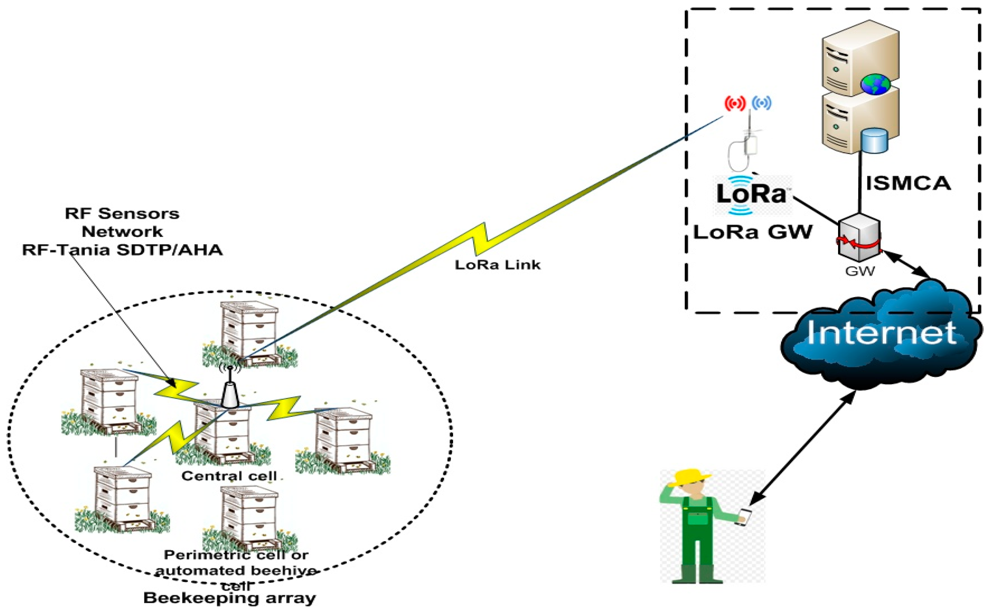
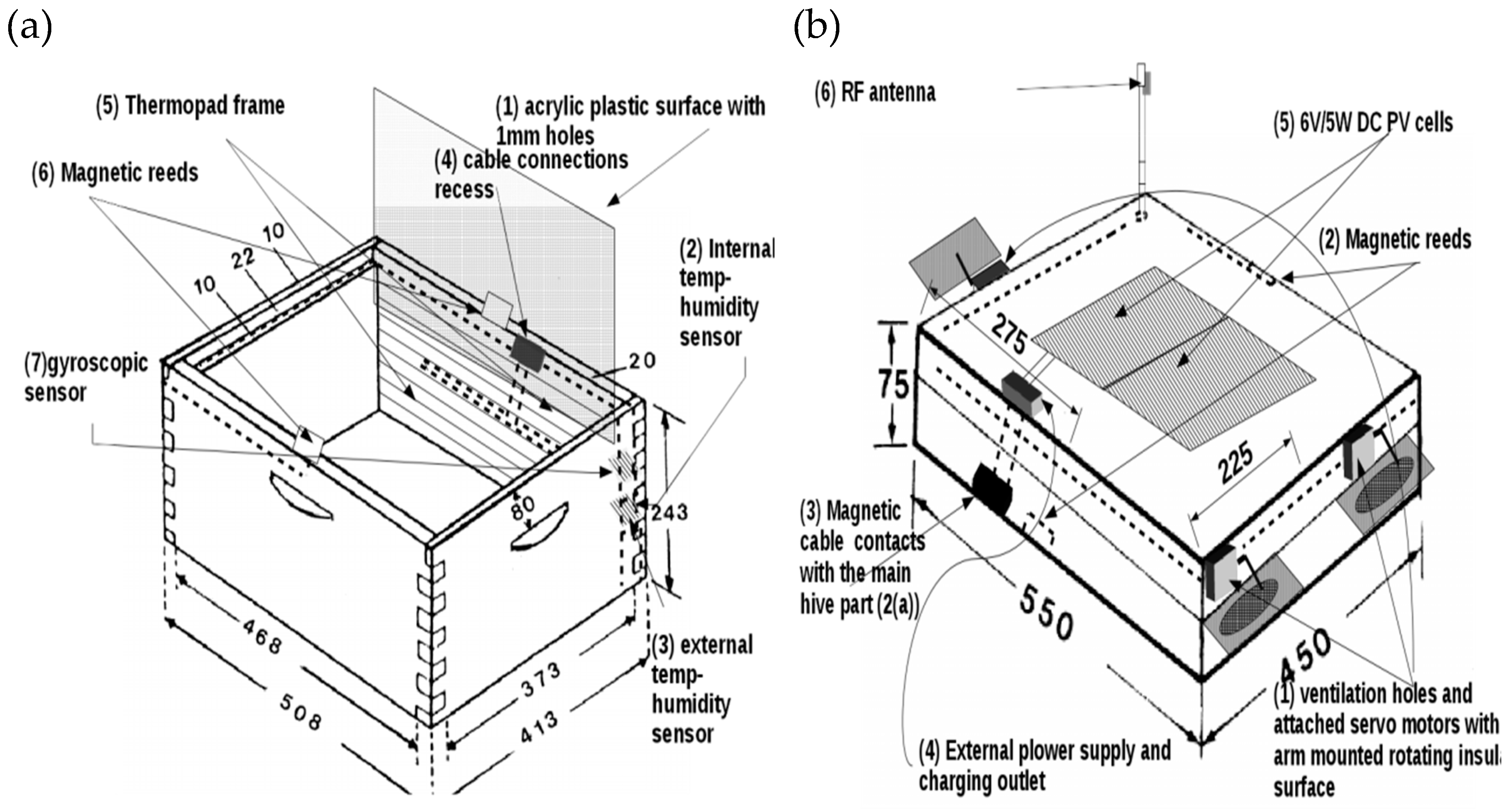
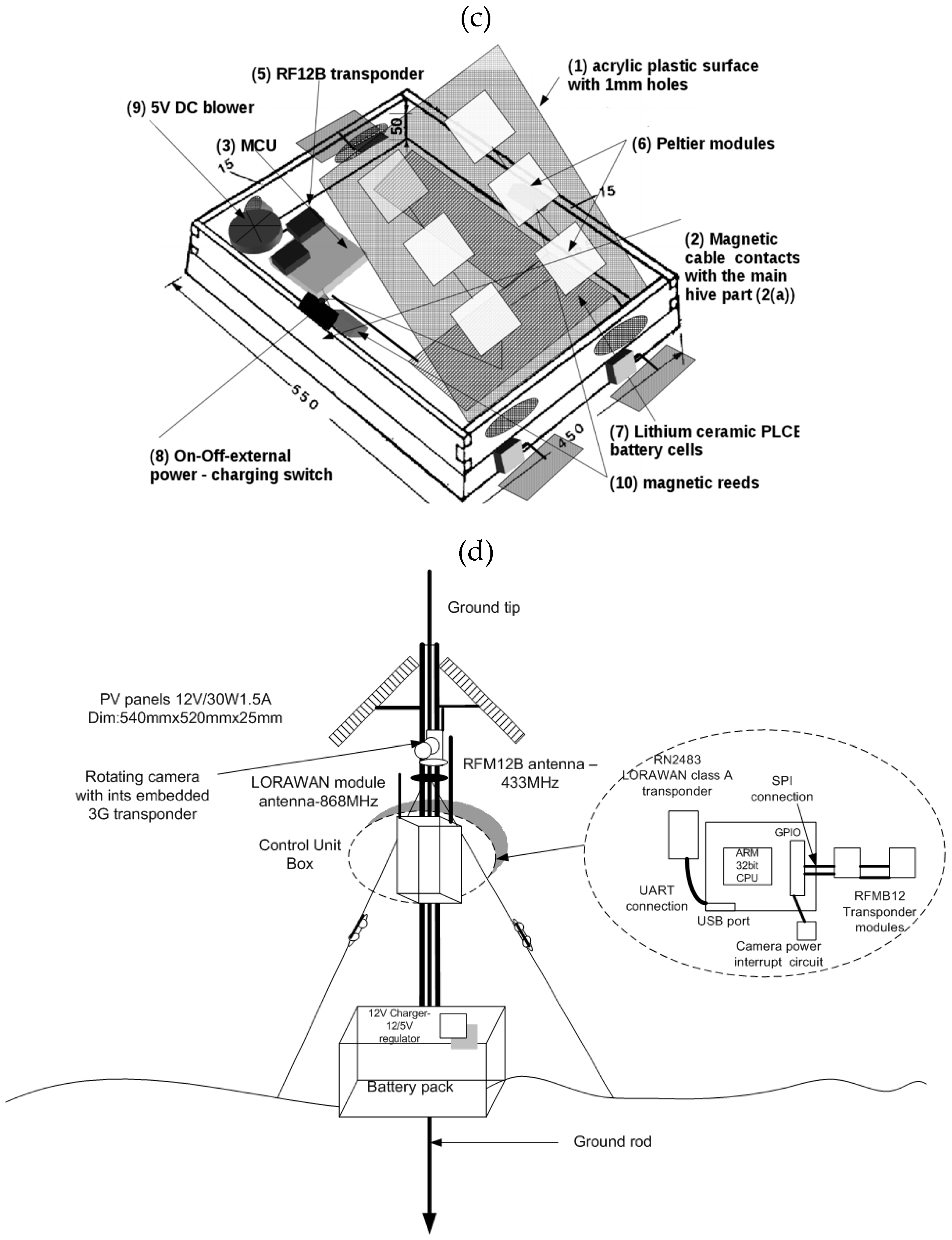
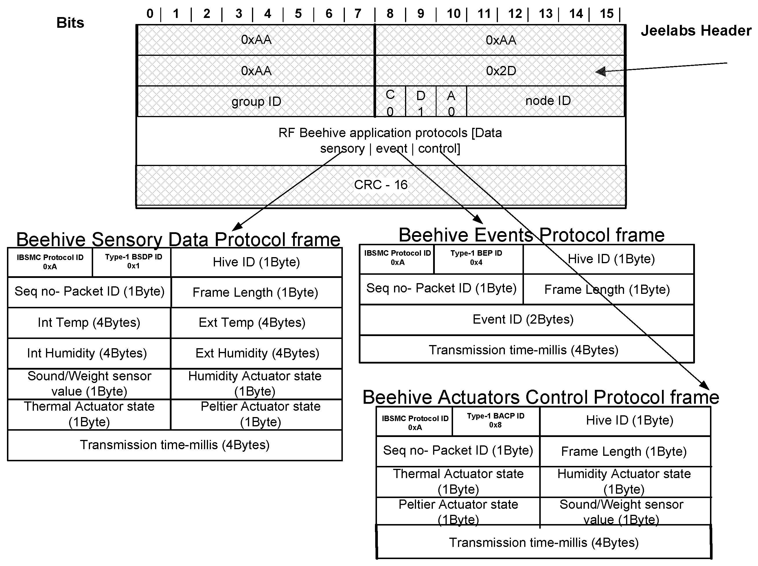
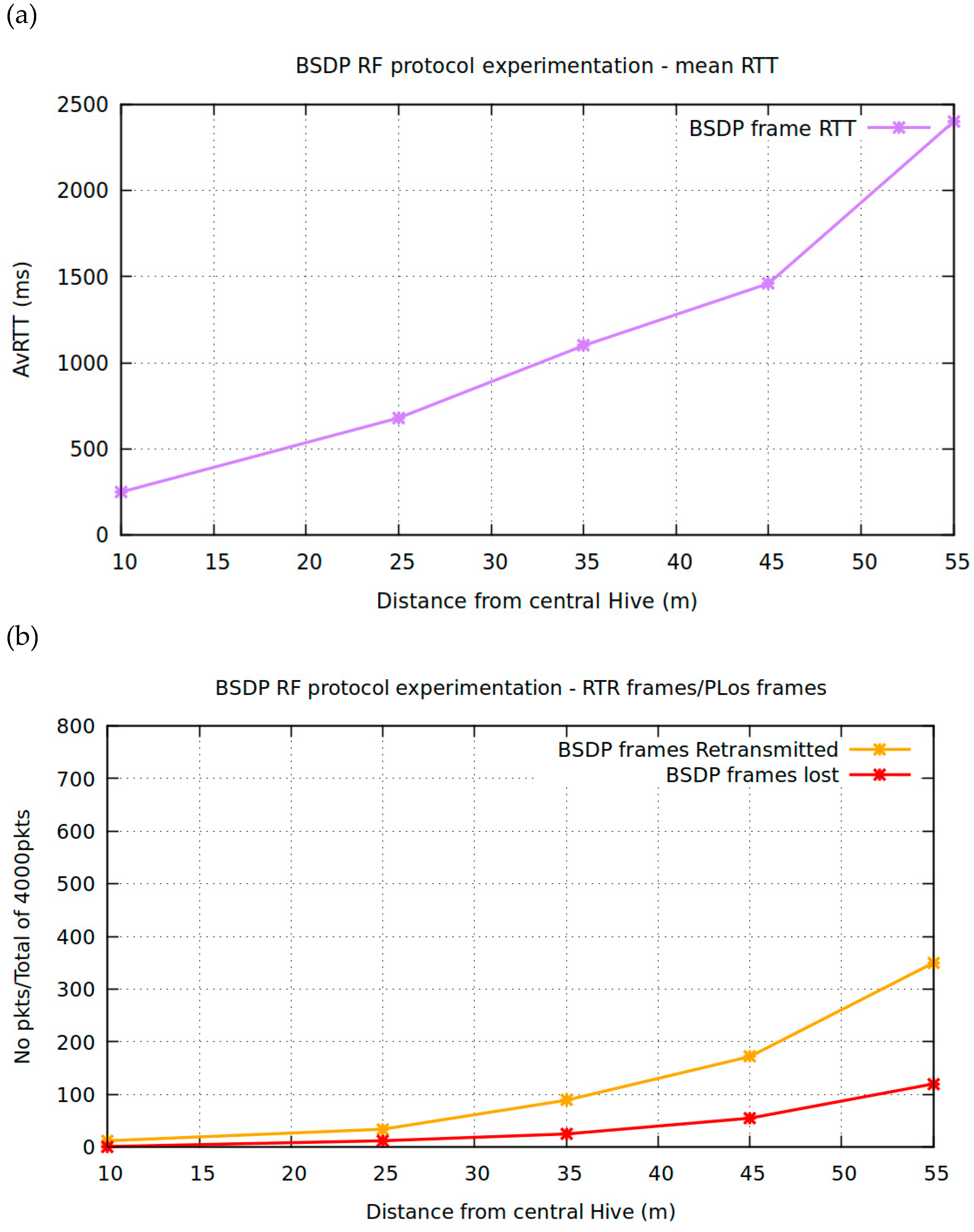
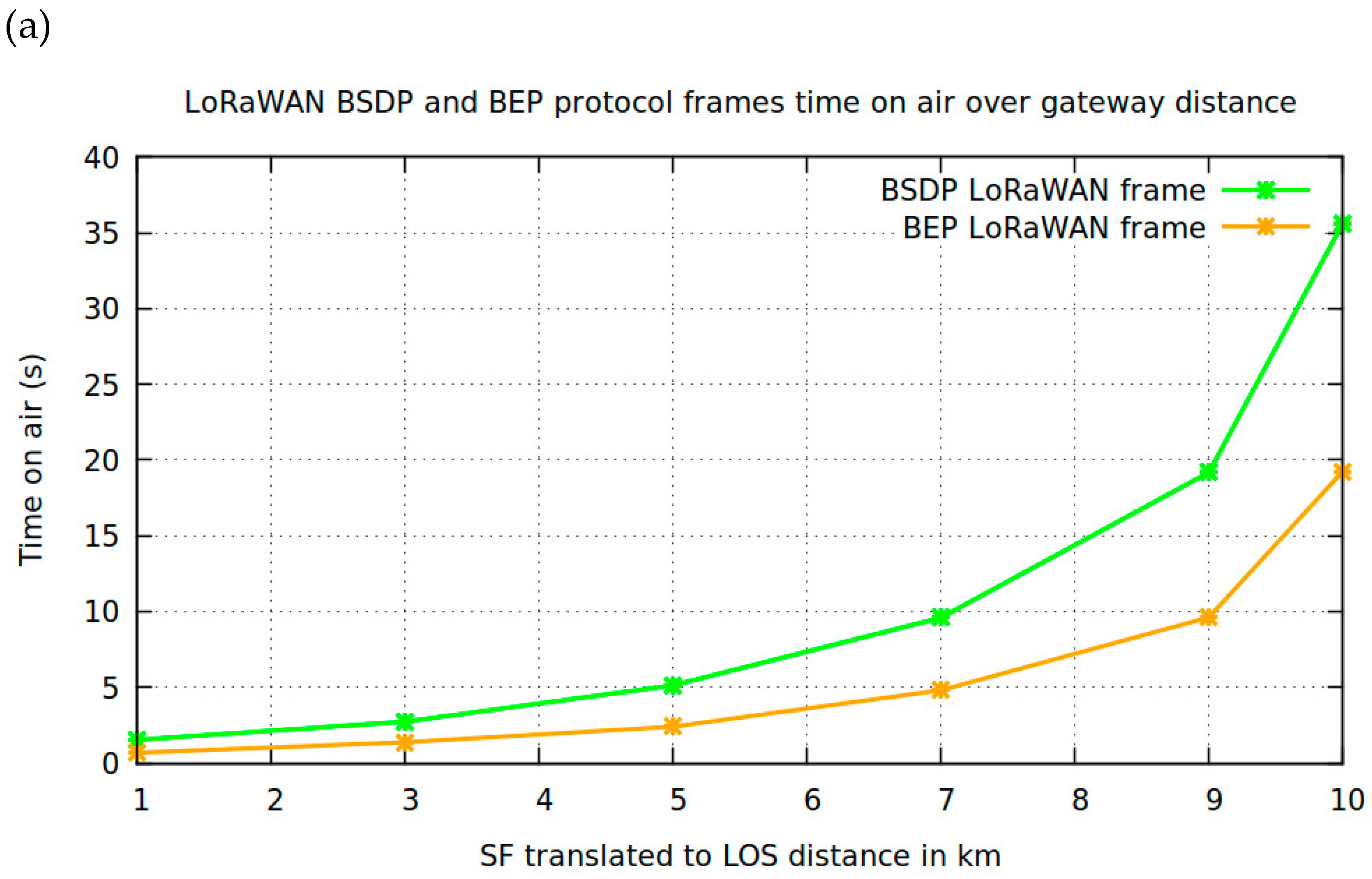
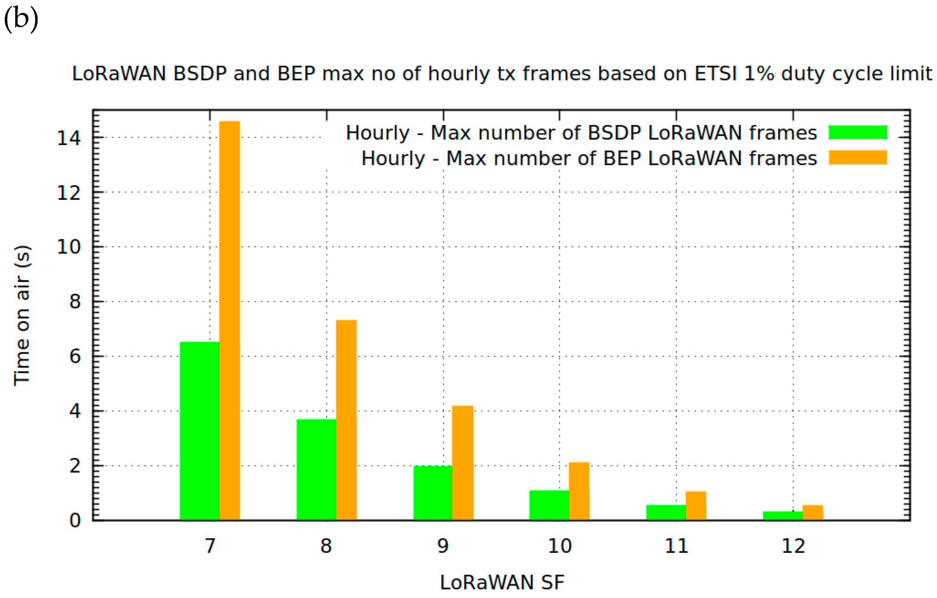
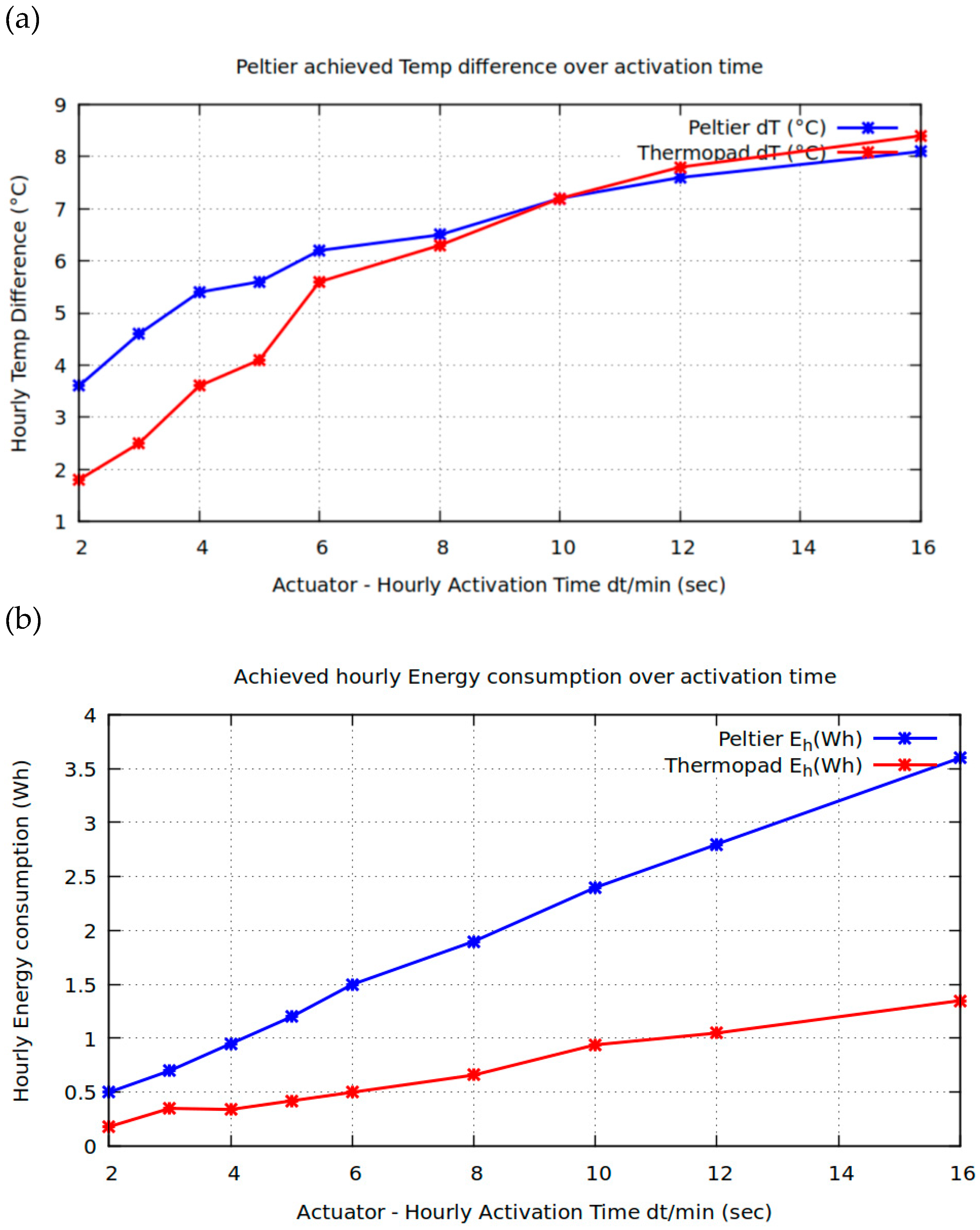
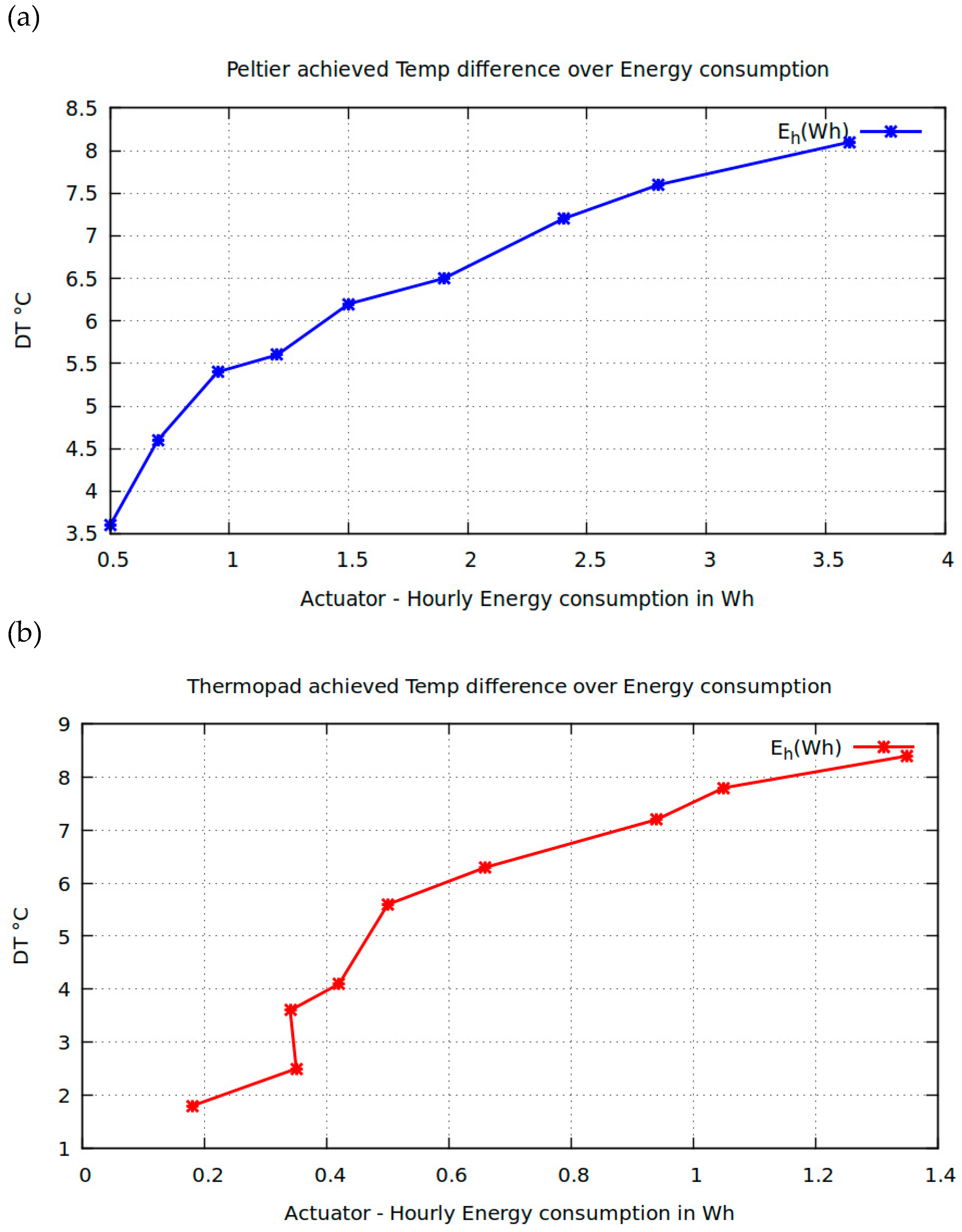
Table 1.
Existing Beehive systems and their capabilities.
| System/Device | Theft Incidents | Mammal Attack Incidents | Wasp Colony Incidents | Temperature/Humidity Monitoring | Environment Conditions Monitoring | Population Monitor | Disease Monitor | Temperature/Humidity Regulation | Energy Foorptint | Deployment Cost |
|---|---|---|---|---|---|---|---|---|---|---|
| Weight scale capable systems/devices [18,19,20] | √ | False Triggers | External Placement | √ | False Triggers | MEDIUM | MEDIUM | |||
| Camera monitoring systems [21,22] | √ | √ | √ | √ | *1 | HIGH | *2 | |||
| GPS systems [23,24] | √ | False Triggers | MEDIUM | HIGH | ||||||
| Electric Fence | √*3 | LOW | LOW | |||||||
| Arnia [26] | √ | False Triggers | √ | √ | √ | √ | HIGH | HIGH | ||
| HiveMind [17] | √ | √ | √ | √ | HIGH | HIGH | ||||
| HiveTech [25] | √ | False Triggers | √ | √ | √ | √ | *4 | HIGH | HIGH | |
| BuzzBox [27] | √ | False Triggers | √ | √ | √ | √ | MEDIUM | MEDIUM | ||
| IBSMC | √ | √ | √ | √ | √ | ?*5 | *6 | √ | LOW*7 | MEDIUM |
* Energy Footprint: It is classified as LOW (more than 3 months of battery autonomy, MEDIUM 1–2 months and HIGH less than one month, *1 internal camera usage is required with image processing algorithms and instance segmentation and detection capabilities., *2 MEDIUM, HIGH if Population Monitoring is required, *3 Automated confrontation without incident feedback, *4 Capability derived from the use of appropriate data mining algorithms, *5 Possible with the installment of triple sound sensor centered in frequencies of 100Hz, 450Hz and 1200 Hz The sound sensor use is still under experimentation ( The reason for the quation mark attahed). in *6 Varroa mite destruction with the use of the thermopad actuator, *7 MEDIUM if temperature control actuators active, LOW if Humidity actuators active, LOW in all other cases.
Table 2.
Cross comparison of 3G/4G transponders with LoRaWAN transponders.
| 3G/4G transponder | Max. Battery used (mAh) | Transmission-Sleep period (min) | Min 3G/4G power consumption on status (mA) | 3G/4G connection and transmission time (s) | Time until battery depletion (days) |
| 10,000 | 1 | 310–360 | 5–20 | 20–30 | |
| LoRaWAN transpoder | Max. Battery used (mAh) | Transmission-Sleep period (min) | Min LoRaWAN Tx and sensors power consumption (mA) | LoRaWAN Tx OTAA join and Tx time (s) | Time until battery depletion (days) |
| 10,000 | 1 | 120–130 | 0.3–2 | 105–170 |
© 2019 by the author. Licensee MDPI, Basel, Switzerland. This article is an open access article distributed under the terms and conditions of the Creative Commons Attribution (CC BY) license (http://creativecommons.org/licenses/by/4.0/).
Share and Cite
MDPI and ACS Style
Kontogiannis, S. An Internet of Things-Based Low-Power Integrated Beekeeping Safety and Conditions Monitoring System. Inventions 2019, 4, 52. https://0-doi-org.brum.beds.ac.uk/10.3390/inventions4030052
AMA Style
Kontogiannis S. An Internet of Things-Based Low-Power Integrated Beekeeping Safety and Conditions Monitoring System. Inventions. 2019; 4(3):52. https://0-doi-org.brum.beds.ac.uk/10.3390/inventions4030052
Chicago/Turabian StyleKontogiannis, Sotirios. 2019. "An Internet of Things-Based Low-Power Integrated Beekeeping Safety and Conditions Monitoring System" Inventions 4, no. 3: 52. https://0-doi-org.brum.beds.ac.uk/10.3390/inventions4030052