Novel Digital Technique to Quantify the Area and Volume of Cement Remaining and Enamel Removed after Fixed Multibracket Appliance Therapy Debonding: An In Vitro Study

 ,
,
Abstract
:1. Introduction
2. Materials and Methods
2.1. Study Design
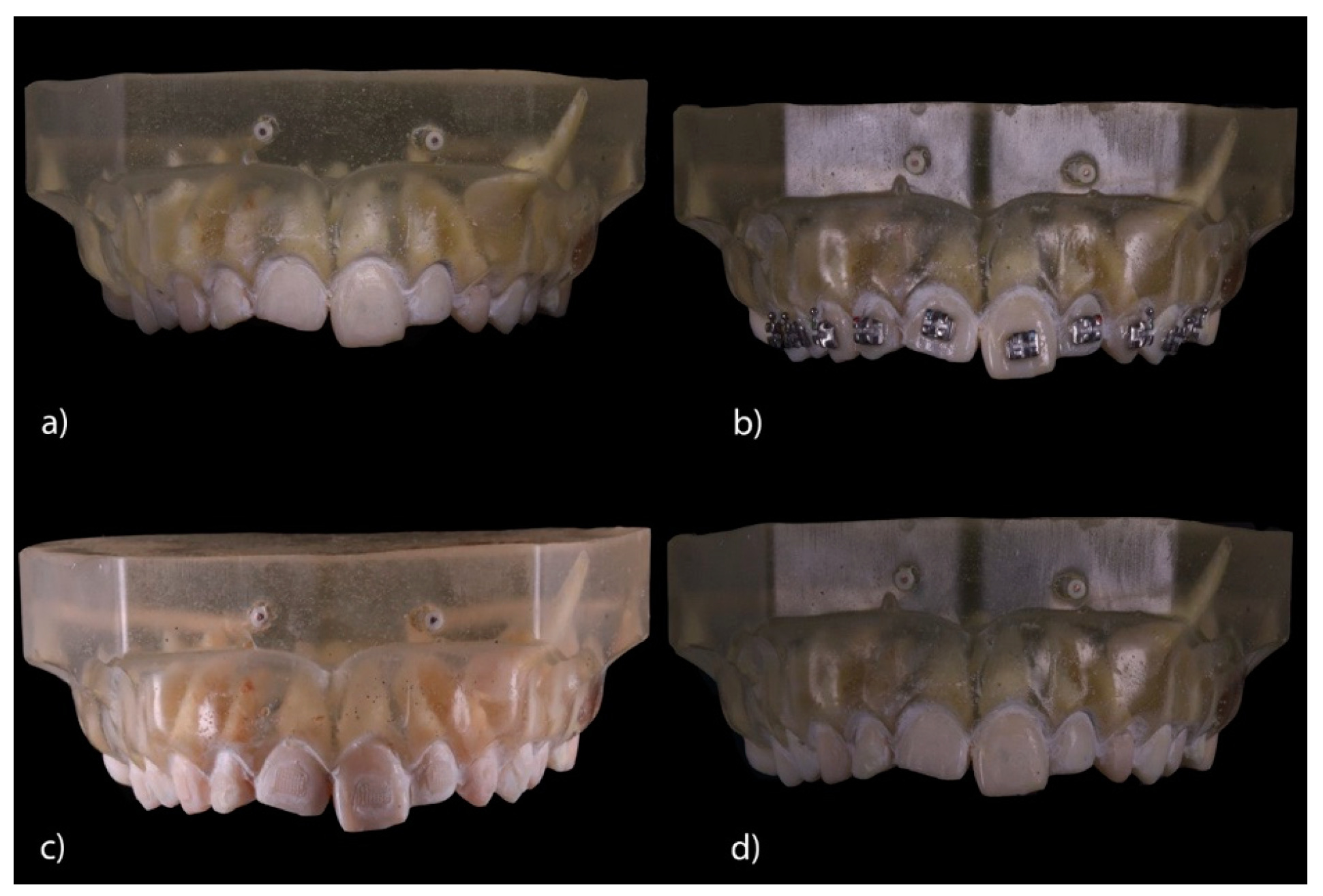
2.2. Experimental Procedure
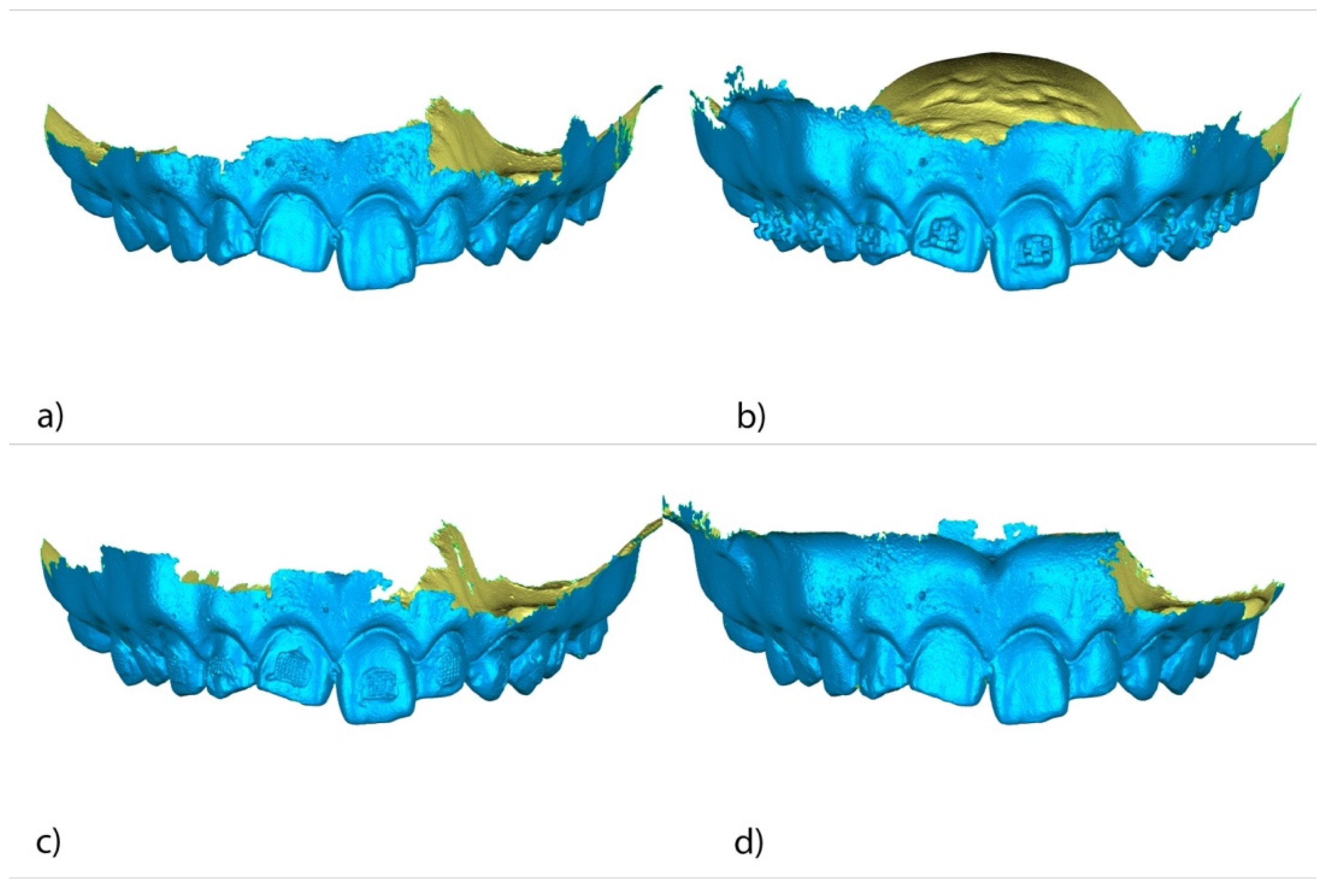
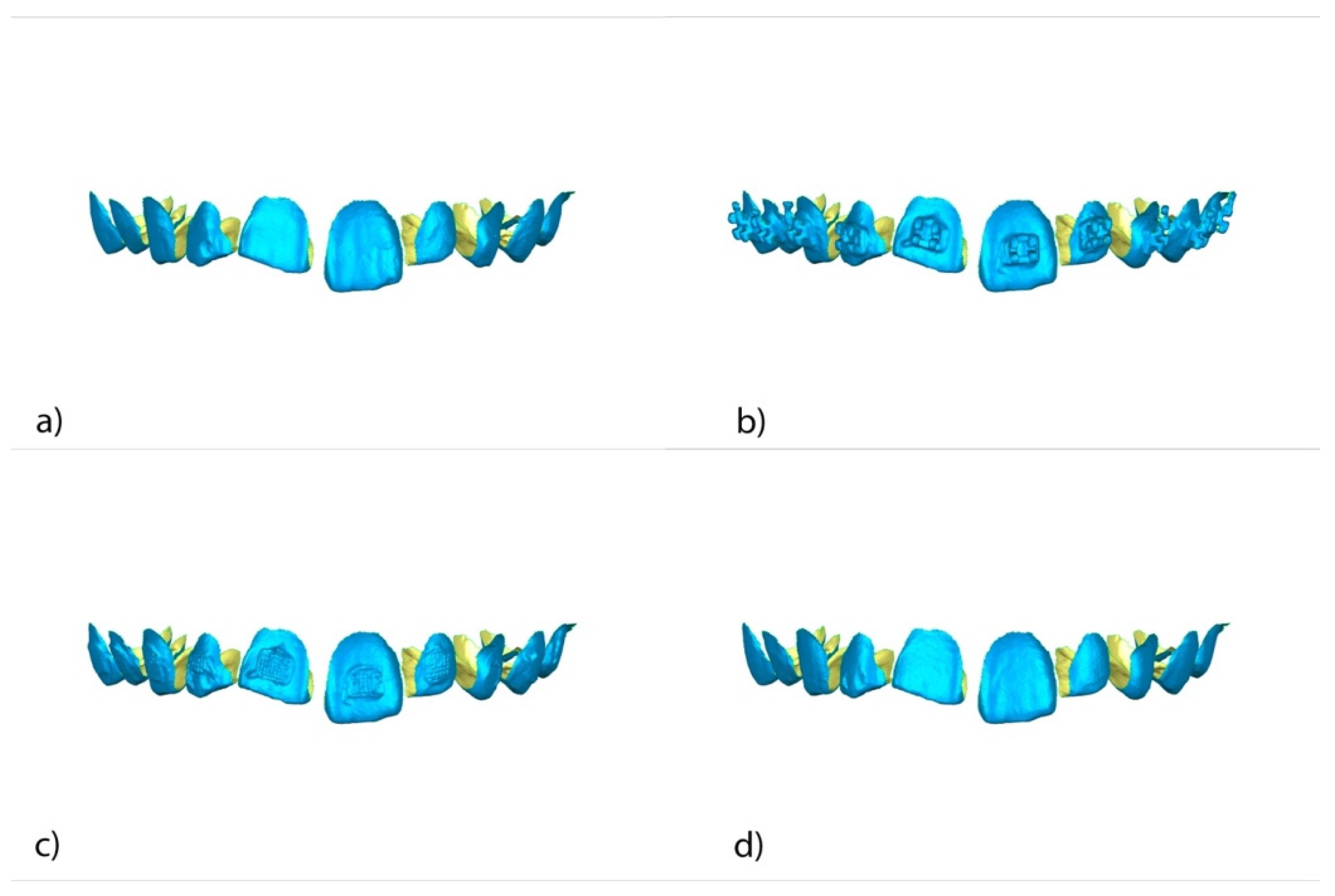
2.3. Alignment Procedure
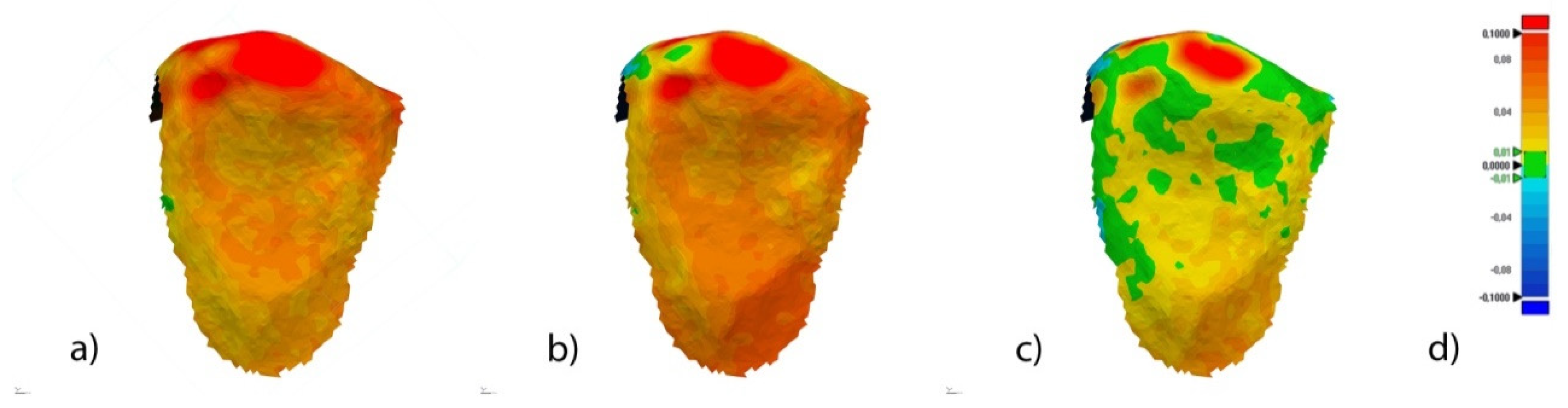
2.4. Measurement Procedure
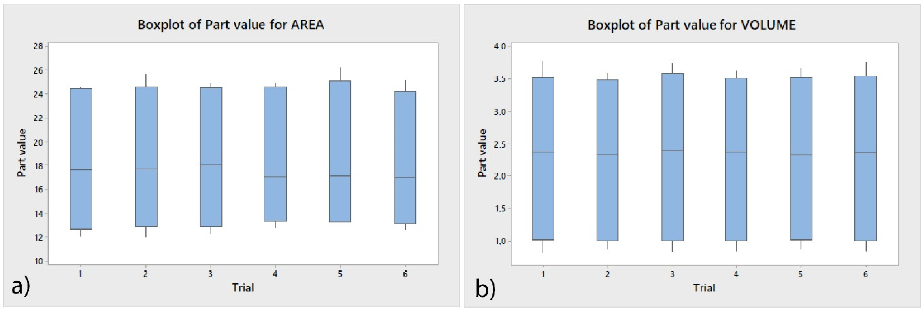
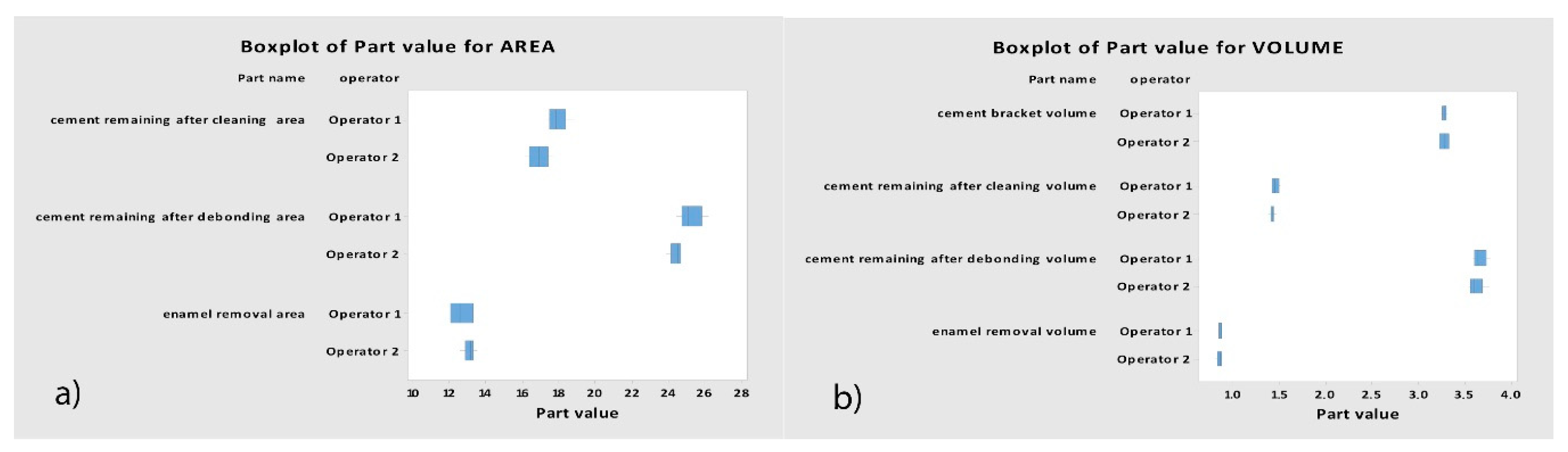
2.5. Validation of the Repeatability and Reproducibility
2.6. Statistical Analysis
3. Results
4. Discussion
5. Conclusions
Author Contributions
Funding
Acknowledgments
Conflicts of Interest
References
- Claudino, D.; Kuga, M.C.; Belizário, L.; Pereira, J.R. Enamel evaluation by scanning electron microscopy after debonding brackets and removal of adhesive remnants. J. Clin. Exp. Dent. 2018, 10, e248–e251. [Google Scholar] [CrossRef] [PubMed]
- Ferreira, F.G.; Nouer, D.F.; Silva, N.P.; Garbui, I.U.; Correr-Sobrinho, L.; Nouer, P.R.A. Qualitative and quantitative evaluation of human dental enamel after bracket debonding: A noncontact three-dimensional optical profilometry analysis. Clin. Oral Investig. 2014, 18, 1853–1864. [Google Scholar] [CrossRef] [PubMed]
- Janiszewska-Olszowska, J.; Szatkiewicz, T.; Tomkowski, R.; Tandecka, K.; Grocholewicz, K. Effect of orthodontic debonding and adhesive removal on the enamel—Current knowledge and future perspectives—A systematic review. Med. Sci. Monit. 2014, 20, 1991–2001. [Google Scholar] [PubMed] [Green Version]
- Machoy, M.; Seeliger, J.; Szyszka-Sommerfeld, L.; Koprowski, R.; Gedrange, T.; Woźniak, K. Evaluation of changes in enamel thickness after orthodontic treatment depending on theforce applied to remove orthodontic brackets: OCT analysis and universal testing machine. Adv. Clin. Exp. Med. 2019, 28, 807–813. [Google Scholar] [CrossRef]
- Hintz, J.K.; Bradley, T.G.; Eliades, T. Enamel colour changes following whitening with 10 per cent carbamide peroxide: A comparison of orthodontically-bonded/debonded and untreated teeth. Eur. J. Orthod. 2001, 23, 411–415. [Google Scholar] [CrossRef] [Green Version]
- Bertacci, A.; Lucchese, A.; Chersoni, S.; Zanna, S.; Manuelli, M.; Valdrè, G. Effects of stannous fluoride on eroded enamel permeability. J. Biol. Regul. Homeost. Agents 2018, 32, 1–8. [Google Scholar]
- Kitahara-Céia, F.M.; Mucha, J.N.; Marques dos Santos, P.A. Assessment of enamel damage after removal of ceramic brackets. Am. J. Orthod. Dentofac. Orthop. 2008, 134, 548–555. [Google Scholar] [CrossRef]
- Sifakakis, I.; Zinelis, S.; Eliades, G.; Koletsi, D.; Eliades, T. Enamel gloss changes induced by orthodontic bonding. J. Orthod. 2018, 45, 269–274. [Google Scholar] [CrossRef]
- Joo, H.J.; Lee, Y.K.; Lee, D.Y.; Kim, Y.J.; Lim, Y.K. Influence of orthodontic adhesives and clean-up procedures on the stain susceptibility of enamel after debonding. Angle Orthod. 2011, 81, 334–340. [Google Scholar] [CrossRef] [Green Version]
- Cochrane, N.J.; Lo, T.W.G.; Adams, G.G.; Schneider, P.M. Quantitative analysis of enamel on debonded orthodontic brackets. Am. J. Orthod. Dentofac. Orthop. 2017, 152, 312–319. [Google Scholar] [CrossRef]
- Odegaard, J.; Segner, D. Shear bond strength of metal brackets compared with a new ceramic bracket. Am. J. Orthod. Dentofac. Orthop. 1988, 94, 201–206. [Google Scholar] [CrossRef]
- Bishara, S.E.; Olsen, M.E.; VonWald, L.; Jakobsen, J.R. Comparison of the debonding characteristics of two innovative ceramic bracket designs. Am. J. Orthod. Dentofac. Orthop 1999, 116, 86–92. [Google Scholar] [CrossRef]
- Samruajbenjakul, B.; Kukiattrakoon, B. Shear bond strength of ceramic brackets with different base designs to feldespathic porcelains. Angle Orthod. 2009, 79, 571–576. [Google Scholar] [CrossRef] [PubMed]
- Rodríguez-Chávez, J.A.; Arenas-Alatorre, J.; Belio-Reyes, I.A. Comparative study of dental enamel loss after debonding braces by analytical scanning electron microscopy (SEM). Microsc. Res. Tech. 2017, 80, 680–686. [Google Scholar] [CrossRef]
- MacIeski, K.; Rocha, R.; Locks, A.; Ribeiro, G.U. Effects evaluation of remaining resin removal (three modes) on enamel surface after bracket debonding. Dental Press J. Orthod. 2011, 16, 146–154. [Google Scholar] [CrossRef] [Green Version]
- Vidor, M.M.; Felix, R.P.; Marchioro, E.M.; Hahn, L. Enamel surface evaluation after bracket debonding and different resin removal methods. Dental Press J. Orthod. 2015, 20, 61–67. [Google Scholar] [CrossRef] [Green Version]
- Eminkahyagil, N.; Arman, A.; Çetinşahin, A.; Karabulut, E. Effect of resin-removal methods on enamel and shear bond strength of rebonded brackets. Angle Orthod. 2006, 76, 314–321. [Google Scholar]
- Karan, S.; Kircelli, B.H.; Tasdelen, B. Enamel surface roughness after debonding: Comparison of two different burs. Angle Orthod. 2010, 80, 1081–1088. [Google Scholar] [CrossRef]
- Hosein, I.; Sherriff, M.; Ireland, A.J. Enamel loss during bonding, debonding, and cleanup with use of a self-etching primer. Am. J. Orthod. Dentofac. Orthop. 2004, 126, 717–724. [Google Scholar] [CrossRef]
- Faria-Junior, E.M.; Giraldo, R.D.; Berger, S.B.; Correr, A.B.; Correr-Sobrinho, L.; Ruiz Contreras, E.F.; Lopes, M.B. In-vivo evaluation of the surface roughnedd and morphology of enamel after bracket removal and polishing by different techniques. Am. J. Orthod. Dentofac. Orthop. 2015, 147, 324–329. [Google Scholar] [CrossRef]
- Leäo Filho, J.C.; Braz, A.K.; de Araujo, O.M.; Tanaka, O.M.; Pithon, M.M. Enamel quality after debonding: Evaluation by optical coherence tomography. Braz. Dent. J. 2015, 26, 384–389. [Google Scholar] [CrossRef] [PubMed]
- Abduo, J.; Elseyoufi, M. Accuracy of Intraoral Scanners: A Systematic Review of Influencing Factors. Eur. J. Prosthodont. Restor. Dent. 2018, 26, 101–121. [Google Scholar] [PubMed]
- Renne, W.; Ludlow, M.; Fryml, J.; Schurch, Z.; Mennito, A.; Kessler, R.; Lauer, A. Evaluation of the accuracy of 7 digital scanners: An in vitro analysis based on 3-dimensional comparisons. J. Prosthet. Dent. 2017, 118, 36–42. [Google Scholar] [CrossRef] [PubMed]
- Medina-Sotomayor, P.; Pascual-Moscardo, A.; Camps, A.I. Accuracy of 4 digital scanning systems on prepared teeth digitally isolated from a complete dental arch. J. Prosthet. Dent. 2019, 121, 811–820. [Google Scholar] [CrossRef] [PubMed]
- Zachrisson, B.U.; Arthun, J. Enamel surface appearance after various debonding techniques. Am. J. Orthod. 1979, 75, 121–127. [Google Scholar] [CrossRef]
- Schuler, F.S.; van Waes, H. SEM-evaluation of enamel surfaces after removal of fixed orthodontic appliances. Am. J. Dent. 2003, 16, 390–394. [Google Scholar]
- Bauman, D.F.; Brauchli, L.; van Waes, H. The influence of dental loupes on the quality of adhesive removal in orthodontic debonding. J. Orofac. Orthop. 2011, 72, 125–132. [Google Scholar] [CrossRef]
- Stadler, O.; Dettwiler, C.; Meller, C.; Dalstra, M.; Verna, C.; Conner, T. Evaluation of a fluorescence-aided identification technique (FIT) to assist clean-up after orthodontic bracket debonding. Angle Orthod. 2019, 89, 876–882. [Google Scholar] [CrossRef] [Green Version]
- Meller, C.; Klein, C. Fluorescence of composite resins: A comparison among properties of commercial shades. Dent. Mater. J. 2015, 34, 754–765. [Google Scholar] [CrossRef] [Green Version]
- Volpato, C.A.M.; Pereira, M.R.C.; Silva, F.S. Fluorescence of natural teeth and restorative materials, methods for analysis and quatification: A literature review. J. Esthet. Restor. Dent. 2018, 30, 397–407. [Google Scholar] [CrossRef]
- Tecco, S.; Tetè, S.; D’Atillio, M.; Festa, F. Enamel surface after debracketing of orthodontic brackets bonded with flowable orthodontic composite. A comparison with a traditional orthodontic composite resin. Minerva Stomatol. 2008, 57, 81–94. [Google Scholar] [PubMed]
- Jivanescu, A.; Rotar, P.; Hategan, S.; Pricop, C.; Rus, R.; Goguta, L. Clinical Factors Influence the Trueness of Intra-oral Scanning. Eur. J. Prosthodont. Restor. Dent. 2019, 27, 51–55. [Google Scholar] [PubMed]
- Ender, A.; Attin, T.; Mehl, A. In vivo precision of conventional and digital methods of obtaining complete-arch dental impressions. J. Prosthet. Dent. 2016, 115, 313–320. [Google Scholar] [CrossRef] [PubMed] [Green Version]
- Kuhr, F.; Schmidt, A.; Rehmann, P.; Wostmann, B. A new method for assessing the accuracy of full arch impressions in patients. J. Dent. 2016, 55, 68–74. [Google Scholar] [CrossRef] [PubMed]
- Guth, J.F.; Runkel, C.; Beuer, F.; Stimmelmayr, M.; Edelhoff, D.; Keul, C. Accuracy of five intraoral scanners compared to indirect digitalization. Clin. Oral Investig. 2017, 21, 1445–1455. [Google Scholar] [CrossRef]
- Ender, A.; Zimmermann, M.; Mehl, A. Accuracy of complete and partial-arch impressions of actual intraoral scanning systems in vitro. Int. J. Comput. Dent. 2019, 22, 11–19. [Google Scholar]
- Nedelcu, R.G.; Persson, A.S. Scanning accuracy and precision in 4 intraoral scanners: An in vitro comparison based on 3-dimensional analysis. J. Prosthet. Dent. 2014, 112, 1461–1471. [Google Scholar] [CrossRef]
- Akyalcin, S.; Cozad, B.E.; English, J.D.; Colville, C.D.; Laman, S. Diagnostic accuracy of impression-free digital models. Am. J. Orthod. Dentofacial. Orthop. 2013, 144, 916–922. [Google Scholar] [CrossRef]
- Guth, J.F.; Keul, C.; Stimmelmayr, M.; Beuer, F.; Edelhoff, D. Accuracy of digital models obtained by direct and indirect data capturing. Clin. Oral Investig. 2013, 17, 1201–1208. [Google Scholar] [CrossRef]
- Ender, A.; Mehl, A. Accuracy of complete-arch dental impressions: A new method of measuring trueness and precision. J. Prosthet. Dent. 2013, 109, 121–128. [Google Scholar] [CrossRef] [Green Version]
- Zanobini, A.; Sereni, B.; Catelani, M.; Ciani, L. Repeatability and reproducibility techniques for the analysis of measurement systems. Measurement 2016, 86, 125–132. [Google Scholar] [CrossRef]
- Carrión García, A.; Grisales Del Río, A.M. Number of distinct data categories and gage repeatability and reproducibility. A doble (but single) requirement. Measurement 2013, 46, 2514–2518. [Google Scholar]


| n | Mean | SD | Minimum | Maximum | |
|---|---|---|---|---|---|
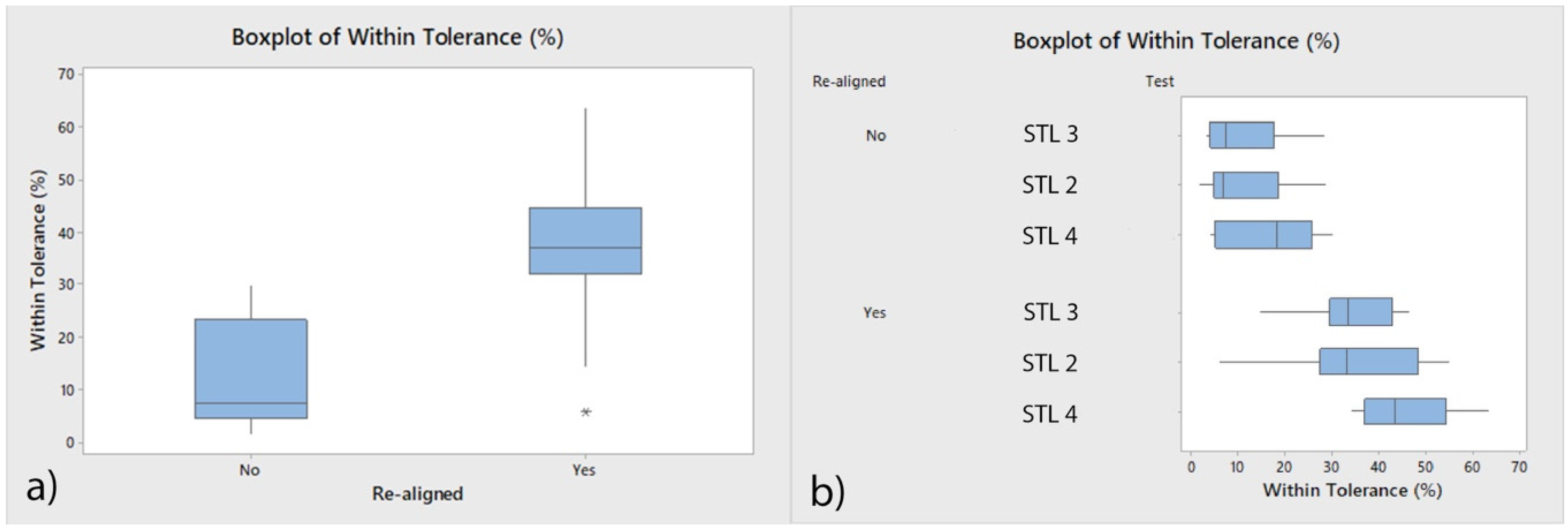
| Aligned (µm) | 30 | 12.75 a | 9.80 | 1.58 | 29.71 |
| Re-aligned (µm) | 30 | 37.88 b | 12.22 | 5.62 | 63.41 |
| Variable | n | Mean | SD | Minimum | Maximum |
|---|---|---|---|---|---|
| Area of remaining cement after bracket removal (µm2) | 12 | 24.8030 | 0.6340 | 23.8450 | 26.1720 |
| Volume of remaining cement after bracket removal (µm3) | 12 | 3.6417 | 0.0761 | 3.5398 | 3.7745 |
| Area of remaining cement after cement removal (µm2) | 12 | 17.4010 | 0.7650 | 16.1370 | 18.7650 |
| Volume of remaining cement after cement removal (µm3) | 12 | 1.4392 | 0.0351 | 1.3766 | 1.5138 |
| Area of enamel removed after cement removal (µm2) | 12 | 12.8390 | 0.5110 | 11.9900 | 13.4810 |
| Volume of enamel removed after cement removal (µm3) | 12 | 0.8576 | 0.0211 | 0.8114 | 0.8844 |
| Volume of cement used to adhere brackets (µm3) | 12 | 3.2794 | 0.0366 | 3.2146 | 3.3242 |
| Operator | n | Mean | SD | Minimum | Maximum | |
|---|---|---|---|---|---|---|
| A | Area of remaining cement after bracket removal (µm2) | 6 | 25.208 | 0.631 | 24.410 | 26.172 |
| B | Area of remaining cement after bracket removal (µm2) | 6 | 24.397 | 0.303 | 23.845 | 24.678 |
| A | Volume of remaining cement after bracket removal (µm3) | 6 | 3.6620 | 0.0742 | 3.5840 | 3.7745 |
| B | Volume of remaining cement after bracket removal (µm3) | 6 | 3.6213 | 0.0789 | 3.5398 | 3.7600 |
| A | Area of remaining cement after cement removal (µm2) | 6 | 17.929 | 0.519 | 17.361 | 18.765 |
| B | Area of remaining cement after cement removal (µm2) | 6 | 16.873 | 0.591 | 16.137 | 17.676 |
| A | Volume of remaining cement after cement removal (µm3) | 6 | 1.4564 | 0.0353 | 1.4221 | 1.5138 |
| B | Volume of remaining cement after cement removal (µm3) | 6 | 1.4220 | 0.0276 | 1.3766 | 1.4605 |
| A | Area of enamel removed after cement removal (µm2) | 6 | 12.606 | 0.588 | 11.990 | 13.274 |
| B | Area of enamel removed after cement removal (µm2) | 6 | 13.071 | 0.314 | 12.563 | 13.481 |
| A | Volume of enamel removed after cement removal (µm3) | 6 | 0.8604 | 0.0163 | 0.8318 | 0.8757 |
| B | Volume of enamel removed after cement removal (µm3) | 6 | 0.8547 | 0.0263 | 0.8114 | 0.8844 |
| A | Volume of cement used to adhere brackets (µm3) | 6 | 3.2823 | 0.0271 | 3.2397 | 3.3175 |
| B | Volume of cement used to adhere brackets (µm3) | 6 | 3.2765 | 0.0468 | 3.2146 | 3.3242 |
© 2020 by the authors. Licensee MDPI, Basel, Switzerland. This article is an open access article distributed under the terms and conditions of the Creative Commons Attribution (CC BY) license (http://creativecommons.org/licenses/by/4.0/).
Share and Cite
Zubizarreta-Macho, Á.; Triduo, M.; Alonso Pérez-Barquero, J.; Guinot Barona, C.; Albaladejo Martínez, A. Novel Digital Technique to Quantify the Area and Volume of Cement Remaining and Enamel Removed after Fixed Multibracket Appliance Therapy Debonding: An In Vitro Study. J. Clin. Med. 2020, 9, 1098. https://0-doi-org.brum.beds.ac.uk/10.3390/jcm9041098
Zubizarreta-Macho Á, Triduo M, Alonso Pérez-Barquero J, Guinot Barona C, Albaladejo Martínez A. Novel Digital Technique to Quantify the Area and Volume of Cement Remaining and Enamel Removed after Fixed Multibracket Appliance Therapy Debonding: An In Vitro Study. Journal of Clinical Medicine. 2020; 9(4):1098. https://0-doi-org.brum.beds.ac.uk/10.3390/jcm9041098
Chicago/Turabian StyleZubizarreta-Macho, Álvaro, Martina Triduo, Jorge Alonso Pérez-Barquero, Clara Guinot Barona, and Alberto Albaladejo Martínez. 2020. "Novel Digital Technique to Quantify the Area and Volume of Cement Remaining and Enamel Removed after Fixed Multibracket Appliance Therapy Debonding: An In Vitro Study" Journal of Clinical Medicine 9, no. 4: 1098. https://0-doi-org.brum.beds.ac.uk/10.3390/jcm9041098