On the Role of Bonding Time on Microstructure and Mechanical Properties of TLP Bonded Al/Mg2Si Composite

1
Department of Mechanical, Industrial and Manufacturing Engineering, Oregon State University, Corvallis, OR 97330, USA
2
School of Metallurgy and Materials Engineering, University of Tehran, Tehran 11554563, Iran
*
Author to whom correspondence should be addressed.
J. Compos. Sci. 2019, 3(3), 66; https://0-doi-org.brum.beds.ac.uk/10.3390/jcs3030066
Submission received: 21 May 2019
/
Revised: 18 June 2019
/
Accepted: 28 June 2019
/
Published: 1 July 2019
Abstract
:Transient liquid phase diffusion bonding of an aluminum metal matrix composite with 15 wt.% Mg2Si reinforcement particles using Cu powder interlayer at 560 °C for different bonding times has been studied. Three different zones were identified at the bonding line: athermally solidified zone, isothermally solidified zone and base metal. By increasing the bonding time, due to the diffusion of copper to the substrate, the width of the athermally solidified zone decreased, became more homogenous and the amount of intermetallic phase (CuAl2) decreased. Therefore, the shear strength increased to a maximum of 60 MPa for the samples with a holding time of 5 h at the bonding temperature.
1. Introduction
Aluminum alloys are substantially employed in the automotive industry and aerospace due to formability, superior strength-to-weight ratio, corrosion resistance, and recyclability and castability [1,2]. Recently, the substantial need to use lightweight materials in aerospace and automotive industries has prompted research to improve the mechanical properties of lightweight alloys such as aluminum and magnesium. In this sense, efforts have been made to develop aluminum metal matrix composite (AlMMC) by adding different types of reinforcement particles such as SiC and Al2O3 to improve the mechanical properties of MMC [3,4,5].
The emergence of using additive manufacturing processes such as selective laser melting (SLM) or selective laser sintering (SLS) processes changed the traditional way of manufacturing of metallic components [6,7,8,9]; however, traditional manufacturing processes such as casting, forging and extrusion are still preferable techniques to produce aluminum alloys and AlMMC parts due to low absorptivity of the laser beam, tenacious oxide films, and low boiling point of aluminum. Also, aluminum alloys are reactive and require using a high vacuum or high purity inert gas atmosphere for SLM and SLS processes [1,10,11]
A newly developed type of reinforced aluminum composite with Mg2Si particles has been used in the automotive industry due to the need of lower ratio of weight to strength, good wear resistance and good castability [4], especially in the brake system, which using a wear resistance composite is preferable [12]. The Al/Mg2Si composite is produced by in-situ technique; thus, lower cost production and being scalable in large production [4]. However, the difficulties in joining the process of AlMMC hinder widespread industrial application [3]. Different techniques were used to join the AlMMC, but each has its own drawbacks [5,13,14]. For example, mechanical fastening may damage reinforcement particles of the composite, and fusion welding may form low viscosity melt; resulting in the evolution of occluded gas. This occluded gas could cause extensive cracking in the heat affected zone and weld porosities. Also, the high temperature of melt could cause the reaction of reinforcement particles and matrix, producing a detrimental intermetallic compound on the interface [13]. Furthermore, in solid state diffusion bonding of AlMMC, the presence of a tenacious and stable aluminum oxide layer on the surface could inhibit metal-to-metal contact; resulting in an improperly joined interface. Overcoming this problem needs the application of high pressure to disrupt the oxide layer and force the surfaces into close contact, causing excessive plastic deformation and losing dimension accuracy [5].
Transient liquid phase (TLP) bonding has been widely used in the joining of AlMMC [5,13,14]. TLP diffusion bonding involves applying an interlayer between two pieces to be joined, and heating to a temperature that forms a thin liquid layer between the two pieces and solidification of the melt at a constant temperature due to inter-diffusion of the liquid’s atoms [5]. The TLP process has advantages of low bonding temperature, low bonding pressure, absence of a heat affected zone, disruption of the surface oxide film by the transient liquid phase, and a low probability of unfavorable reaction.
Maity et al. [15] investigated the role of holding time up to 6 h in microstructure evolution of TLP bonded extruded Al 6061—15 wt.% SiCp composite and achieved bond strength of 90% of the as-received composite using a copper interlayer foil. The common interlayer used for TLP bonding of aluminum composite is copper, due to low bonding temperature; the eutectic temperature of the Al–Cu system is 548 °C, which is far below the solidus temperature of base material to prevent melting or distortion of the base material [15,16,17]. However, different kind of elements such as Ni [18] or a mixture of Cu and Ni [19] were also adopted to join aluminum composites using the TLP technique. Ghayoor et al. [19] demonstrated the feasibility of using mixed Cu-Ni powder as an interlayer in TLP bonding of Al/Mg2Si, achieving 90% shear strength of the as-received composite.
In this study, the TLP bonding process using copper powder was adopted to join the Al/Mg2Si composite and the role of holding time on microstructure evolution and mechanical properties were investigated.
2. Materials and Methods
2.1. Materials and Preparation
The base material, Al/Mg2Si composite, was produced by gravity metal mold casting, containing 15 wt.% Mg2Si particles with average particle size of 30 μm. The chemical composition of the Al/Mg2Si is listed in Table 1. The bonding specimens were cut into 8 mm × 8 mm × 5 mm samples out of parent ingot using wire electrical discharge machining (EDM). The Cu powder (Merck Co.) with particle size of <67µm and purity of >99% was utilized as an interlayer for TLP bonding of Al/Mg2Si composite (Table 2).
2.2. Joining Procedure
The bonding specimens were polished to 1000 grit size, ultrasonically cleaned in an acetone bath for 10 min. Afterward, a batch of 30 mg of the Cu powder was applied on the ultrasonically cleaned surface of one specimen, followed by making of a slurry on the surface of the specimen with the aid of ethanol to make a uniform interlayer. The other specimen was placed on the spread interlayer and pressed to make a joining unit. Then, the joining unit was held using a graphite jig fixture and 0.2 MPa pressure was applied during the entire process to firmly keep the joining surfaces in close contact. After that, the assembly was placed in a tube furnace purged with argon (99.995%) gas and heated at a rate of 10 °C/min to the bonding temperatures of 540 °C, 550 °C and 560 °C. The bonding specimens were held in the furnace for four different times: 30 min, 1 h, 2 h, and 5 h and then the furnace was cooled down to room temperature. The specimens were labeled as Cu-0.5, Cu-1, Cu-2, and Cu-5, respectively.
2.3. Microstructural Analyses
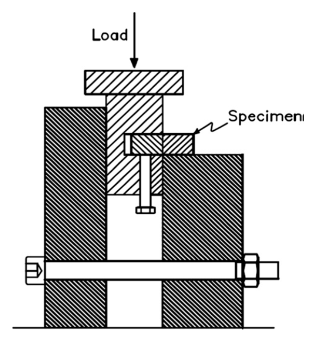
In order to analyze the microstructure of the joined interface, the bonded specimens were cross-sectioned and polished using standard techniques. Microstructure characterization was done by optical microscopy and scanning electron microscopy (SEM, TESCAN), which was equipped with Oxford Instruments X-Max 50 silicon drift energy dispersive X-Ray spectroscopy (EDS) system, at beam acceleration voltage of 15 kV in both secondary electron (SE) and backscattered electron (BSE) modes at the working distance of 12.3 mm. X-ray diffraction (XRD) analysis was conducted on the bonded interface using a Philips X’Pert Pro X-ray diffractometer with a Cu Kα radiation source at 45 kV and 40 mA; the continuous scan mode was used and scan rate was 5°/min. For detection of different phases, Philips PANanalytical X’Pert software was adopted. The shear strength of the bonded joints was evaluated by means of a specially designed fixture, as illustrated in Figure 1, in a tensile testing machine (SANTAM) with a loading speed of 0.1 mm/min. For each bonding condition, three specimens were tested and the average value was reported as the shear strength (bond strength).
3. Results
3.1. Bonding Temperature
The bonded samples at 540 °C, due to lack of enough strength between the specimens, fell apart after the sample was pulled out from the fixture. At 540 °C, the temperature was not high enough to form the liquid in the interlayer; therefore, no bonding was formed between the specimens. Furthermore, the bonded specimens at 550 °C had shown very low bonding strength and there was a considerable gap between the specimens, probably due to low flowability of the formed liquid. The results of these experiments led us to select a bonding temperature of 560 °C, which is above the eutectic temperature of the Al-Cu diagram and below the solidus temperature of the base material [20] and could form adequate liquid with high flowability to fully cover the bonding surface and fill the pours, which will be illustrated in detail in the following sections.
3.2. Microstructure of Base Material and the Bonding Zone
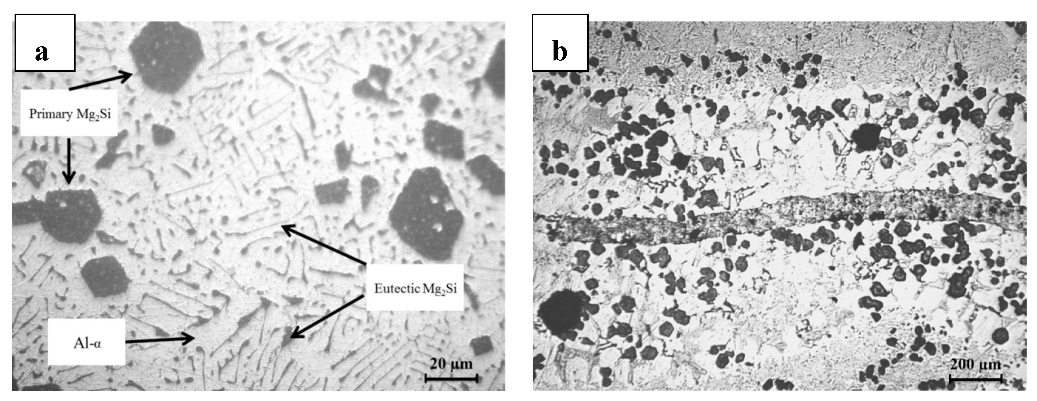
Figure 2a shows the microstructure of the as-polished Al/Mg2Si MMC. The microstructure consists of primary Mg2Si reinforcement particles, eutectic α-Al/Mg2Si, and the α-Al phase, as labeled in Figure 2a. Figure 2b shows the bonding interface of sample Cu-2. The interface line was not straight across the bonding line probably due to the following reasons: (1) The as-received base material had many porosities due to the casting process. Therefore, if these porosities were located in the bonding interface, the formed liquid at the bonding temperature would flow into the porosities and change the shape of the interface; and (2) using Cu powder as an interlayer, due to the inherent interstitial space between the powder particles, could have the same effect as porosities in the matrix and hinder the liquid to spread homogenously at the bonding interface.
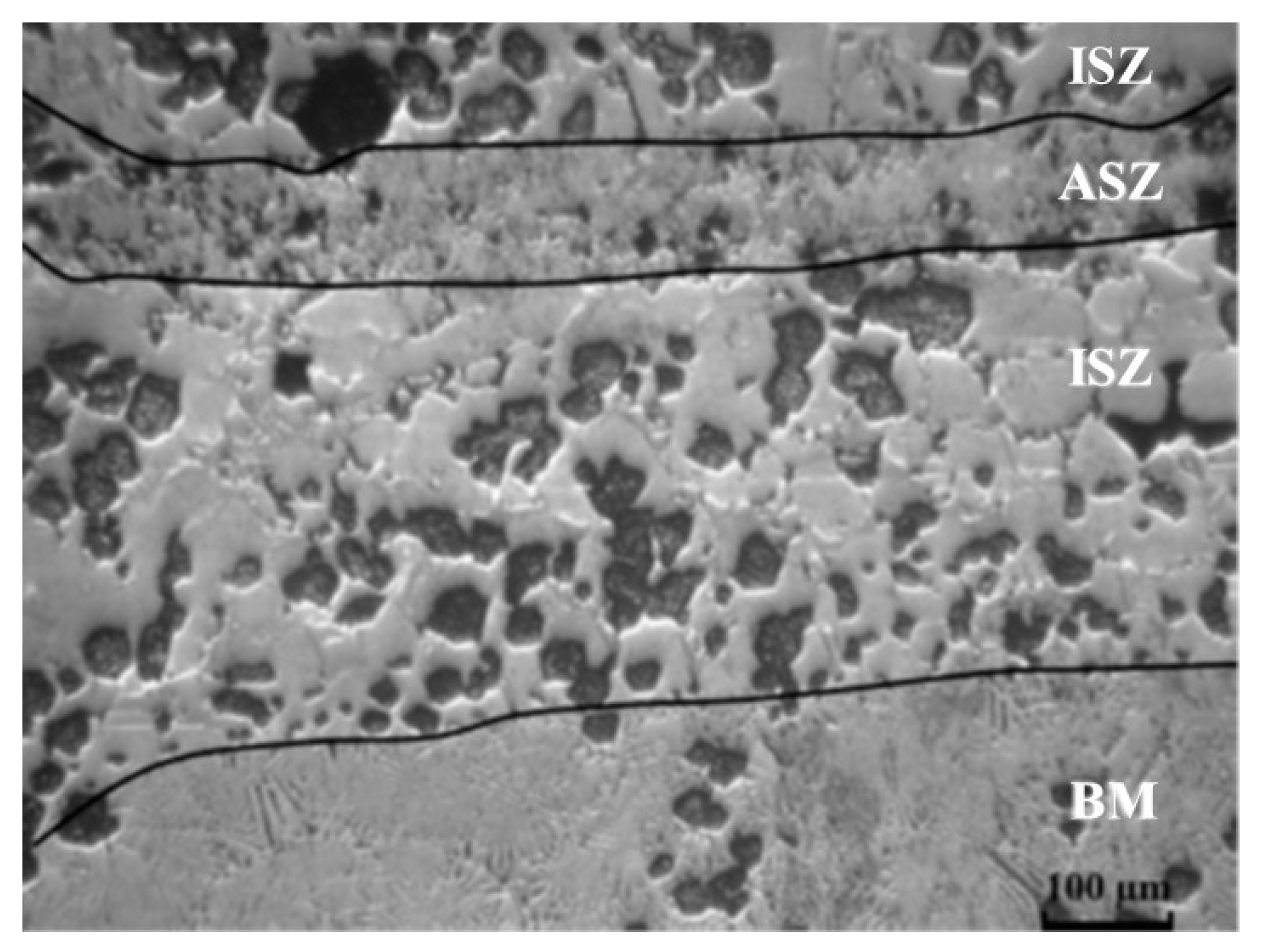
Figure 3 shows the microstructure of the Cu-0.5 sample. It can be observed that three zones exist in the bond region:
- (1)
- Athermally Solidified Zone (ASZ), which solidified by decreasing temperature from bonding temperature to room temperature.
- (2)
- Isothermally Solidified Zone (ISZ), which solidified at the constant temperature (bonding temperature) and segregation of reinforcement particles was obvious in this zone.
- (3)
- Base Material (BM), which did not have an effect on this zone with increasing temperature.
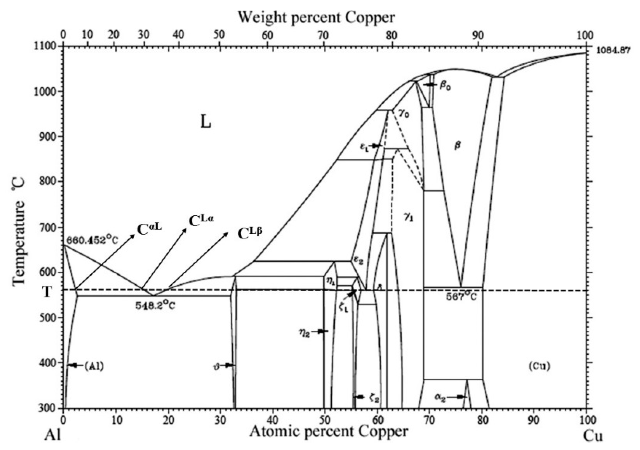
Formation of three different zones in TLP bonding of Al/Mg2Si MMC could be explained according to the phase diagram of Al-Cu, as shown in Figure 4. In the first stage, the copper atoms from the interlayer diffuse to the base metal (aluminum) and aluminum atoms diffuse from the base metal into the copper interlayer. By continuing the diffusion of copper to the aluminum, the copper composition of the contact region between the base metal and interlayer might reach more than CαL composition and these regions could start to be melted and form a liquid in the interface. Then, the copper interlayer and the top layer of the base metal, which were already in contact with the interlayer, could completely dissolve and therefore, the liquid in the bonding interface could reach a chemical composition between CLα and CLβ. Gradually, this interlayer became wider (second stage); dissolving the reinforcement particles that have been trapped in the Al matrix.
The concentration of copper atoms in the interface is higher than the top layer of the base metal, which was in contact with the liquid. The surface of the base metal (Al), which was in contact with the liquid, had a chemical composition of CαL and the liquid had a chemical composition of CLα. From this moment onwards, the isothermal solidification could start by nucleation of the solid embryos on the base metal surface (third stage) and these nuclei have a chemical composition equal to CαL. The solid/liquid interface tries to maintain a thermodynamical balance between CLα of the liquid and CαL of the solid, but since the establishment of such a balance needs solid state diffusion, the speed of moving solid/liquid interface is very slow and this step is time-consuming (fourth stage).
As shown in the Cu-0.5 sample micrograph (Figure 3), the athermally solidified zone had formed, implying that the isothermal solidification stage (third stage) had not been completed. In TLP bonding, if the sufficient time for the isothermal solidification was provided, the melt completely solidifies isothermally and the final structure would be solid-phase with CαL composition. However, if the bonding time was not sufficient, as was the case in our study, while the melt is at the bonding temperature, it continues to isothermally solidify and when the holding time ends, the bonding temperature drops and the melt solidifies conventionally and forms an athermally solidified zone.
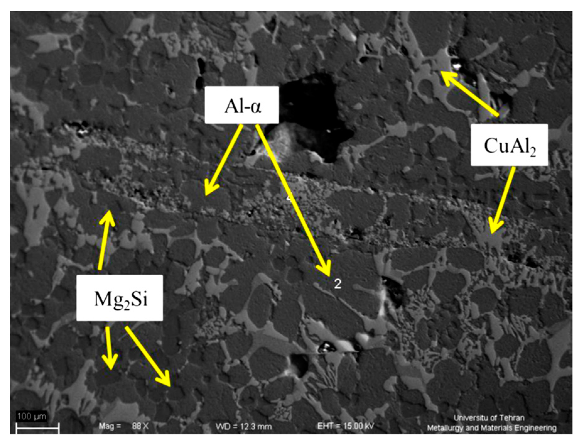
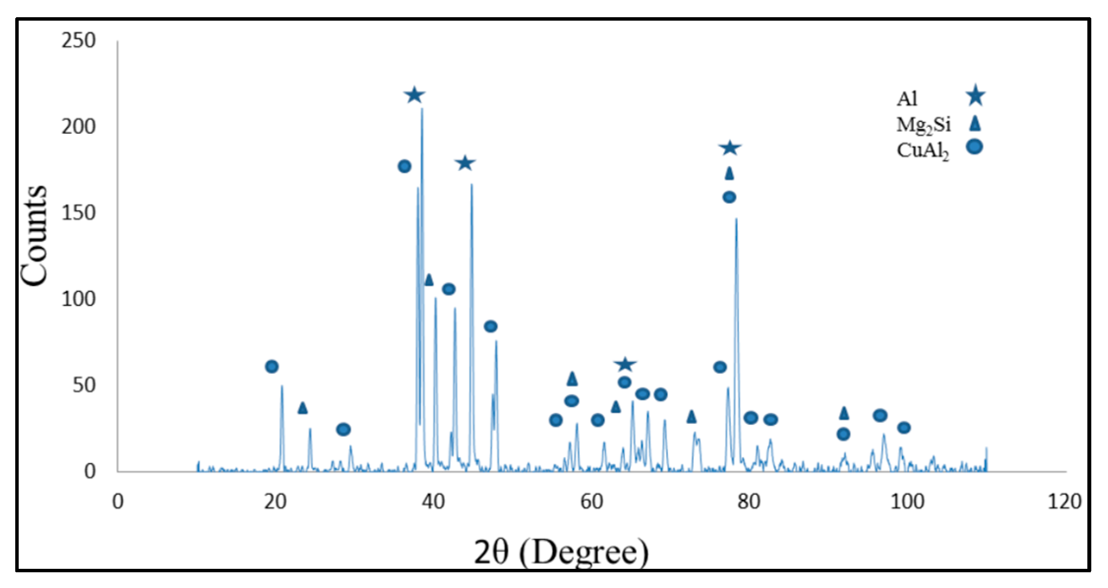
Figure 5 shows the SEM micrograph of sample Cu-2. According to the color contrast in Figure 5, three different phases can be detected in the bonding line: Darkest phase, dark phase, and bright phase. According to the EDS analyses, the darkest phase, with an irregular shape morphology (pointed out in Figure 5), had 64 at.% of Mg and 35 at.% of Si, representing Mg2Si, the reinforcement particles. The dark phase, which is spread on the entire sample, had 98 at.% Al, representing α-Al. Lastly, the bright phase had 64 at.% Al and 34 at.% Cu, representing CuAl2, which is the most possible phase, according to the phase diagram of Al-Cu [20].The XRD analyses from the fracture surface of the bonded surface, as shown in Figure 6, also confirmed the result of the EDS analyses.
4. Discussion
4.1. Athermally Solidification Zone (ASZ)
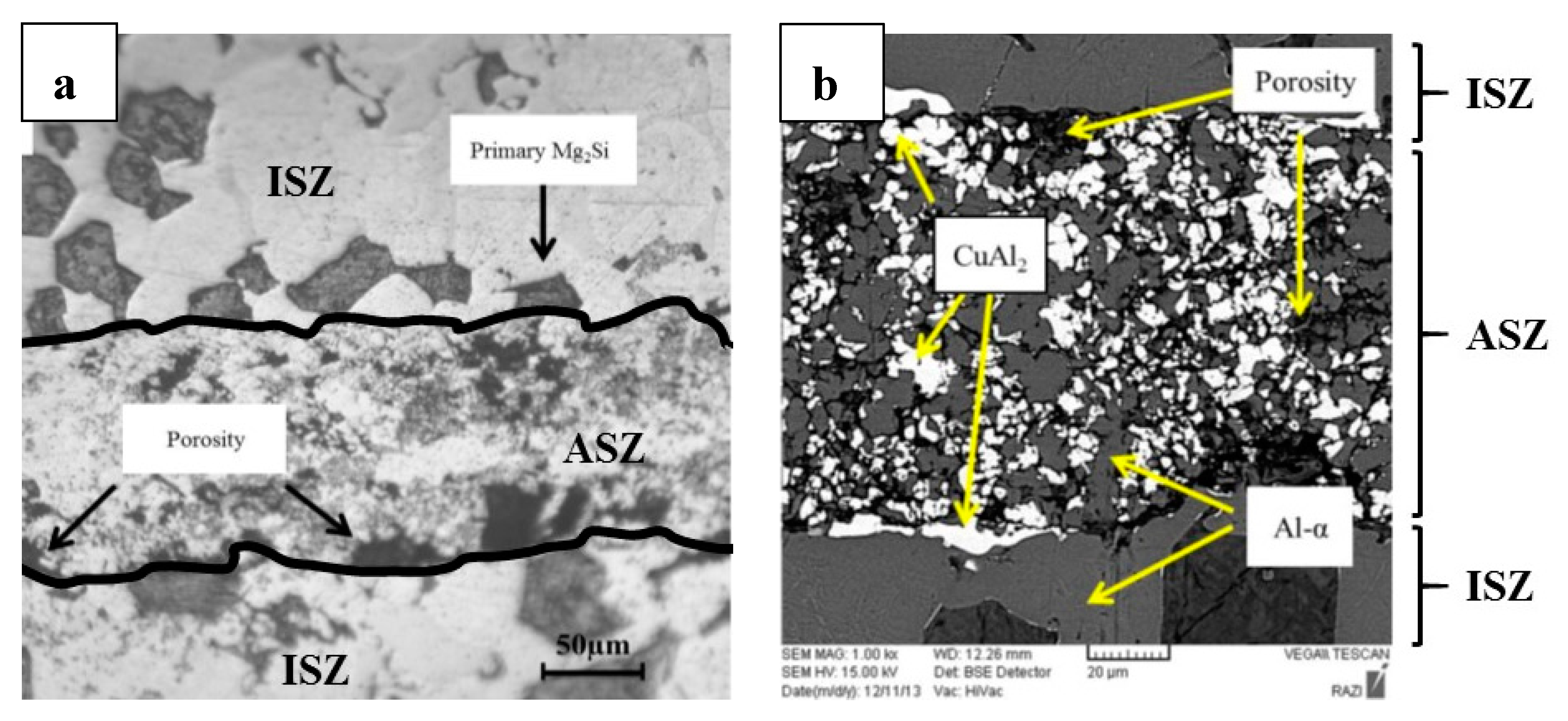
Figure 7 shows the optical and SEM micrograph of the bonding zone, demonstrating porosities in the interlayer. Because large particle size (<67 µm) copper powder was used as the interlayer, although the joining unit was pressed, there were some porosities in ASZ after melting and solidifying the interlayer. The SEM micrograph, Figure 7b, and the EDS analyses illustrated the presence of two different phases in the ASZ: α-Al (dark phase) and CuAl2 (bright phase). The EDS spot analyses of the bright phase showed that the composition of the bright phase was 62 at.% Al and 36 at.% Cu. By the diffusion of Al to the interlayer (Cu), the most probable phase, according to the phase diagram of Al-Cu (Figure 4), is an intermetallic phase of CuAl2.
4.2. Isothermal Solidification Zone (ISZ)
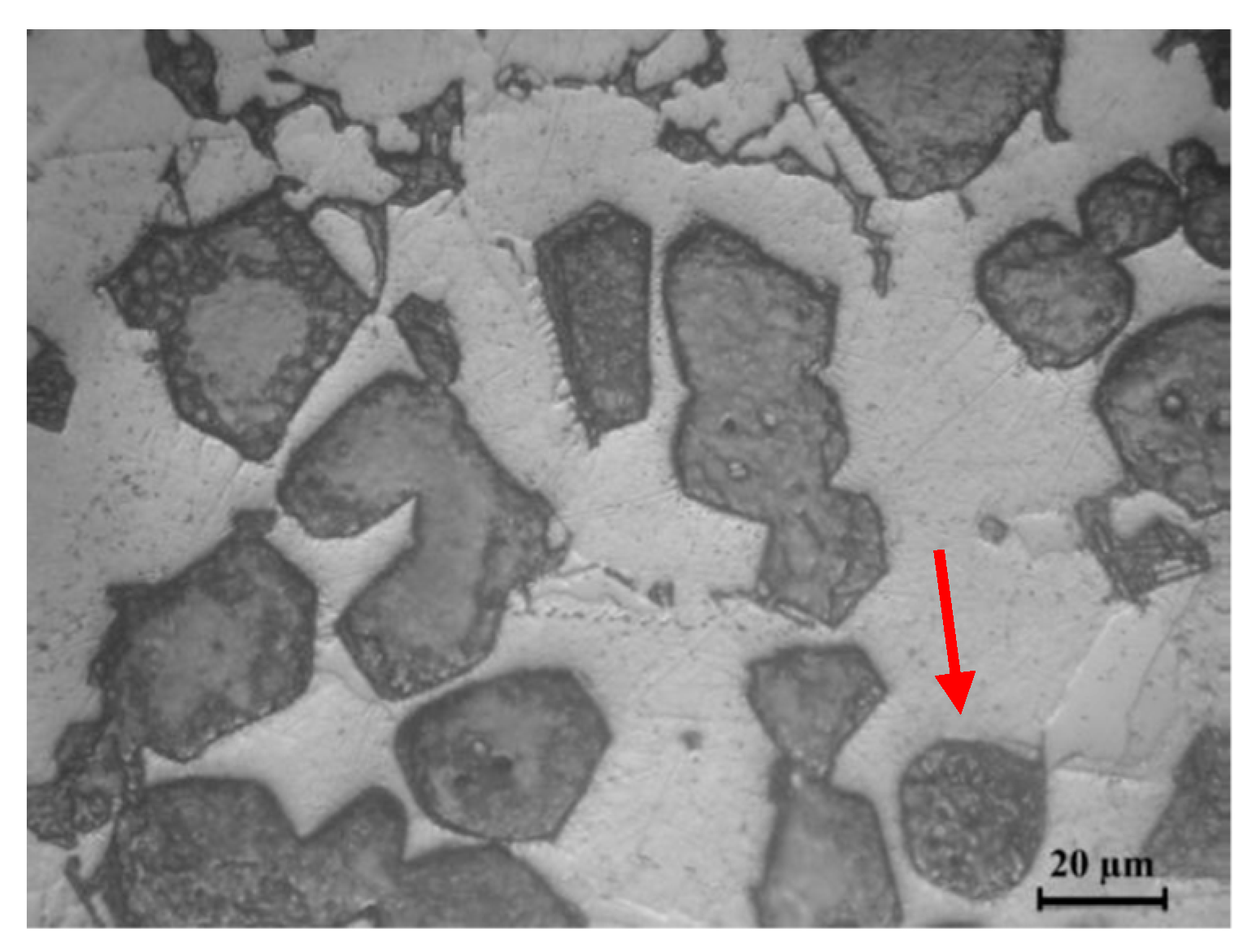
During the isothermal solidification, nucleation of phase α-Al initiates at the interface of liquid and Mg2Si particles, which needs lower activation energy due to heterogeneous nucleation [21]. According to the phase diagram of Al-Mg2Si [22], the melting temperature of Mg2Si is 580 °C; therefore, at the bonding temperature of 560 °C, the eutectic and fiber like Mg2Si did not melt. Figure 8 shows the agglomeration of reinforcement particles in ISZ. The reinforcement particles were attached to each other and agglomerated due to the tendency of lowering surface energy. Agglomerated particles could reduce the surface energy between the particles and the liquid [21]. The eutectic Mg2Si were engulfed in the α-Al phase or joined to the primary Mg2Si, changing the rectangular shape of primary Mg2Si to a more spherical shape (Figure 8).
As shown in Figure 3, Mg2Si particles were segregated and distributed non-uniformly, at two sides of the bonding line, in the ISZ. According to the literature [13,15,16,17] the primary α-Al is very efficient at rejecting insoluble particles, pushing the particles ahead of the solid/liquid interface; thus, particles would segregate at the last stage of solidification. In this regard, a critical velocity for solid/liquid interface has been reported; below the critical velocity, the insoluble particles are pushed by the moving interface and above that, the particles are engulfed. Stefanesco et al. [23] defined the critical velocity of the solid/liquid interface as below:
where Vc is critical velocity, Δσ is surface energy, α is the shape factor of the interface, η is the viscosity of the melt, and R is particle size. The critical velocity (Vc) is directly related to surface energy (Δσ) and inversely related to particle size (R) [23]. Since the first two stages of TLP bonding (dissolution of interlayer and widening of liquid) were taking place instantly, the velocity of solid/liquid interface motion is substantially high [15]. As a result, Mg2Si particles were not pushed away by the solid/liquid interface from the bond centerline during widening of the liquid. In the next stage (isothermal solidification), the velocity of solid/liquid interface motion is very slow, because the solid-state diffusion controls the process, taking several hours to complete. During the isothermal solidification, due to the low velocity of the solid/liquid interface, most Mg2Si particles were pushed by the moving solid/liquid interface, as evident in the present work (Figure 3). Therefore, particles segregated at bond centerline, along with the residual liquid phase that solidified during the cooling stage.
At the isothermal solidification stage, the α-Al nucleates. If there is sufficient time for the isothermal solidification stage to be completed, all the liquid could solidify at the bonding temperature by decreasing the temperature. By decreasing the solubility limit of Cu in Al, CuAl2 precipitated in the Al matrix. In our study, due to insufficient time for completion of the isothermal solidification stage, even in the Cu-5 sample, residual liquid solidified normally, resulting in the final microstructure of:
- (1)
- Isothermal solidified α-Al
- (2)
- Primary α-Al precipitated from the liquid (Cαl), solidifying from the bonding temperature to eutectic temperature
- (3)
- Eutectic (CuAl2+α) phase, which solidified from the liquid under the eutectic temperature
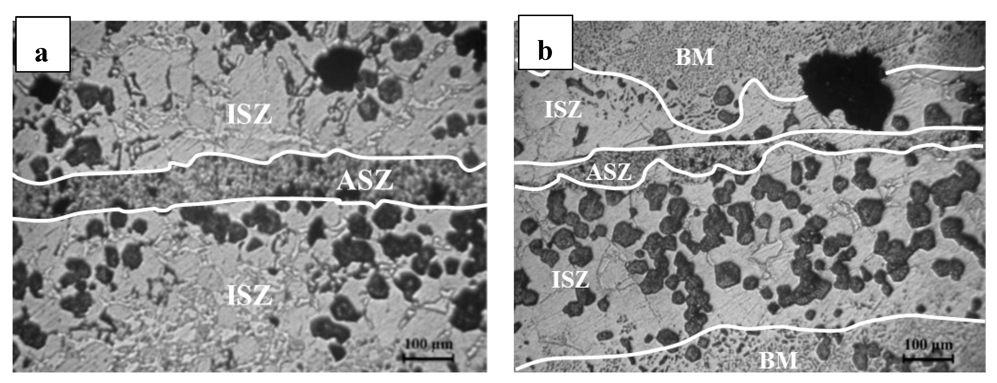
Intermetallic phase CuAl2 decreases strength. All of the samples have shown a quantity of CuAl2; therefore, it is concluded that isothermal solidification has not been completed after 5 h. By increasing the bonding time and growth of isothermal α-Al, the amount of CuAl2 (the brightest phase contrast) decreased as shown in Figure 9.
4.3. Width of ASZ
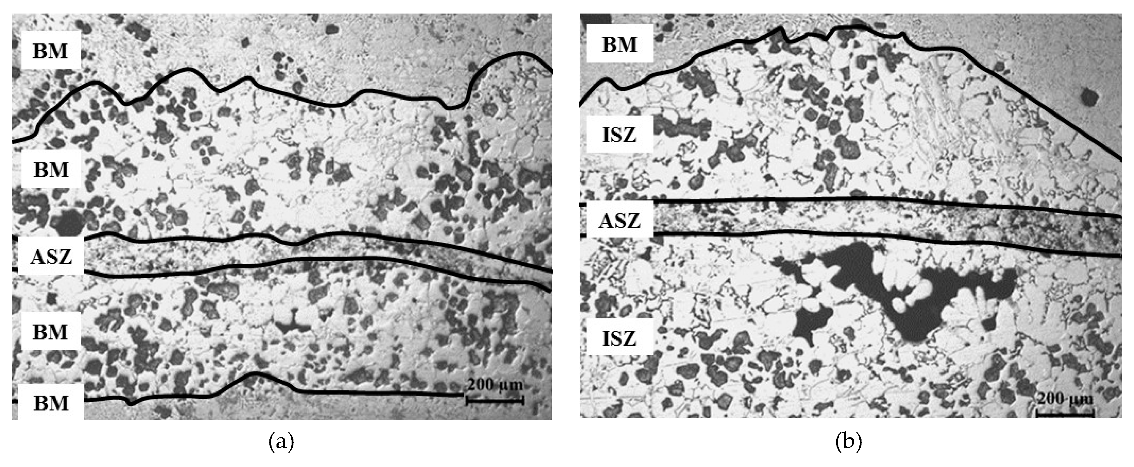
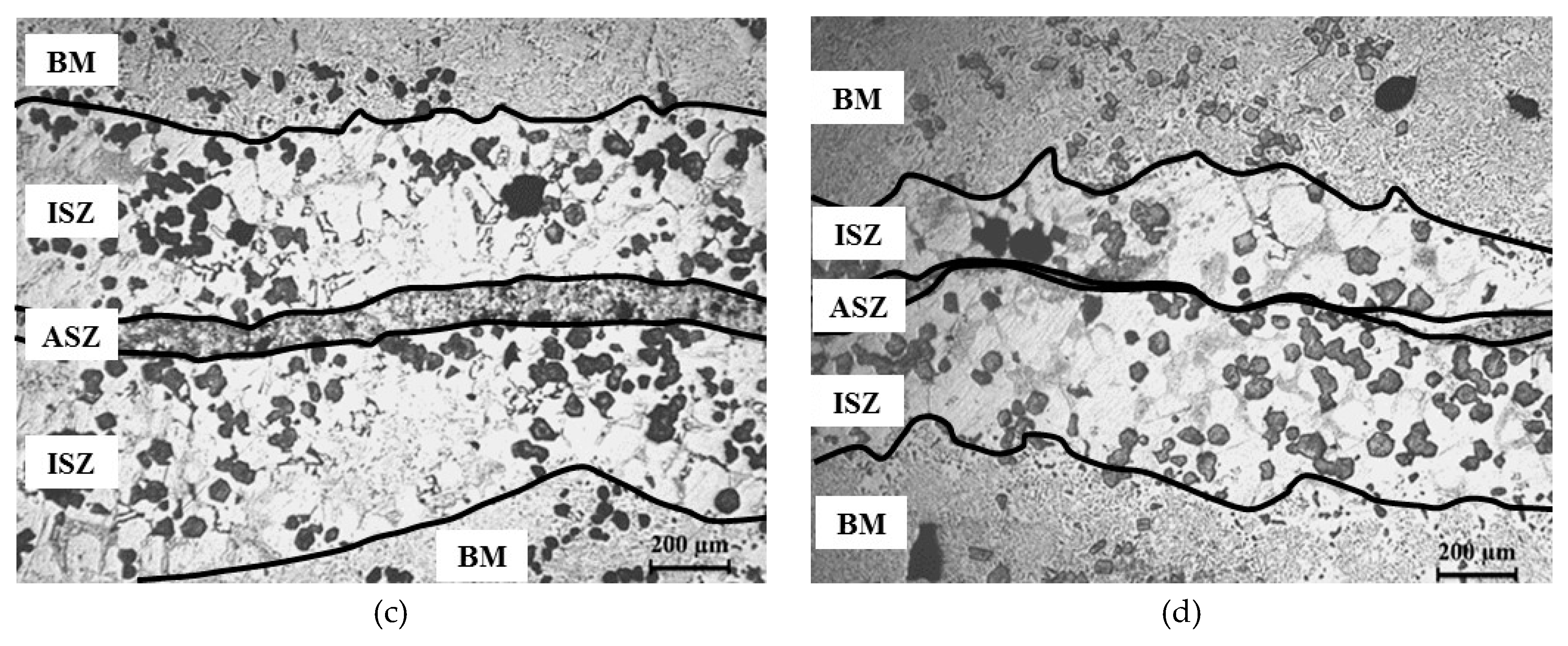
Figure 10 shows the central bonding zones of all the samples. The width of the ASZ was calculated by measuring the mean of ten points (reported in Table 3). As shown in Figure 10, by increasing the bonding time, more Cu could diffuse from the interlayer to the base metal. Therefore, the width of ASZ decreased by increasing holding time due to more diffusion of Cu from the interlayer to the base metal. The width of the segregated zone is related to particle size and the amount of liquid phase (which is related to the thickness of the interlayer and bonding temperature) [17]; therefore, when the amount of liquid phase in the bonding zone decreased, the number of reinforcement particles, which were trapped in the liquid phase, would also reduce, resulting in fewer particle segregation in the bonding zone.
4.4. Shear Strength of Samples
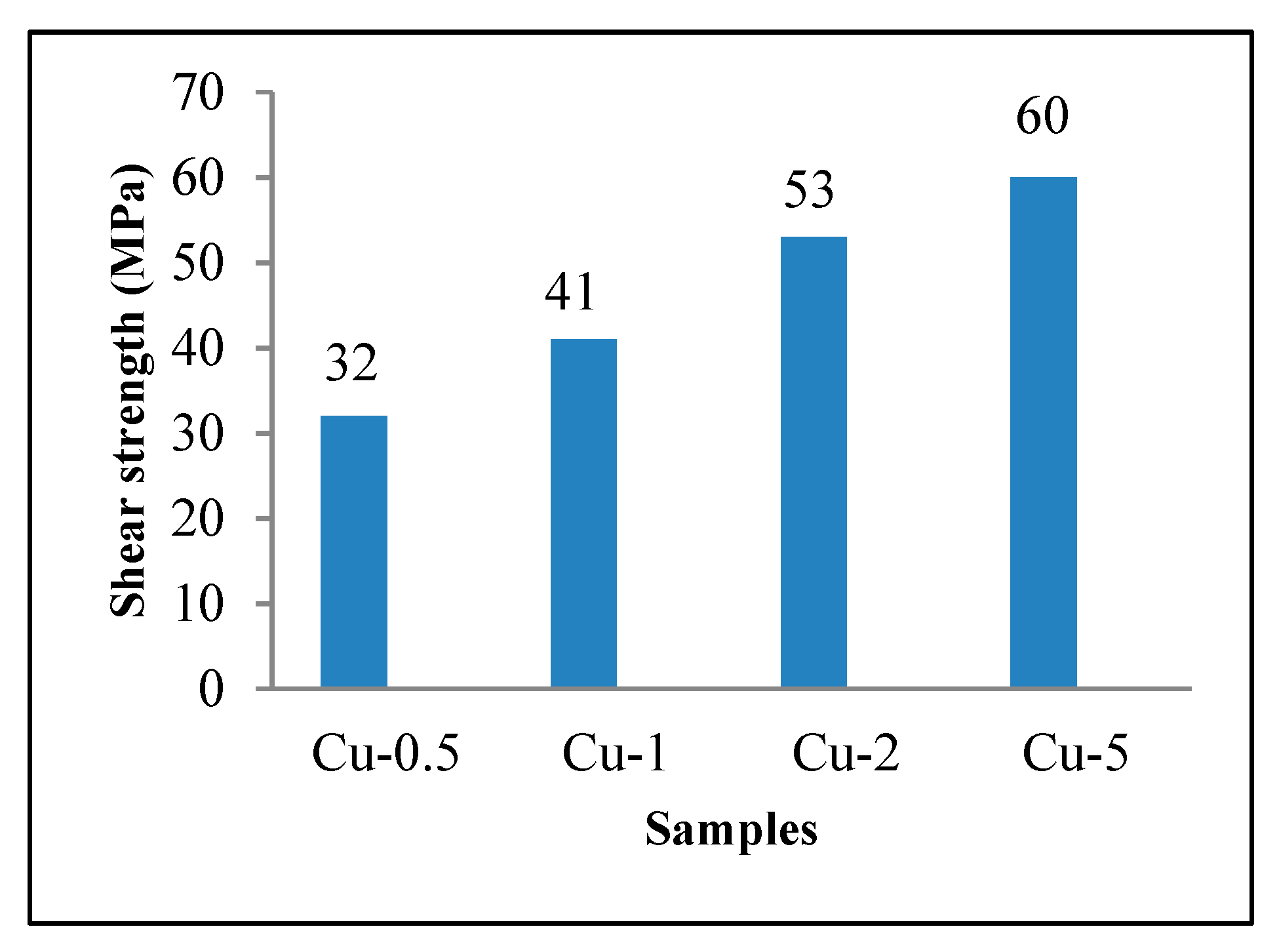
The result of shear strength is given in Figure 11. Shear strength was calculated by dividing the maximum force to the area of the bonding zone. By increasing the bonding time and continuous diffusion, the bonding zone became more homogenous and furthermore, the number of microporosities, preferable spot for crack initiation, decreased [24]. Therefore, by increasing the bonding time, the shear strength increased to a maximum of 60 MPa, which is 75% of the as-received composite. Moreover, by increasing bonding time, the width of ASZ decreased due to the diffusion of Cu; thus, the formation of intermetallic phases, which could potentially weaken the bonding zone, could be avoided. It can be concluded that increasing shear bonding strength is related to decreasing the width of the bonding zone due to diffusion and a smaller amount of brittle phase (CuAl2). In another study by the same author [19], the mixed Cu-Ni powder was used as the interlayer for TLP bonding of Al/Mg2Si. Using mixed Cu-Ni powder yielded a higher shear strength (70 MPa), compared to the Cu interlayer, due to the combined effect of a lower amount of brittle intermetallic phase (CuAl2) and higher viscosity of the formed interlayer, which caused a narrower ISZ in bonded samples using the Cu-Ni mixed powder.
5. Conclusions
- (1)
- Three zones were identified in the bonding interface:
- (i)
- An athermally solidified zone, which was in the center of the bonding line; it had porosities due to the use of Cu power
- (ii)
- An isothermally solidified zone, which can be characterized by the segregation of reinforcement particles
- (iii)
- Base metal, which did not have an effect on the microstructure even with increasing temperature
- (2)
- By increasing bonding time due to the diffusion of copper from the interlayer to the base metal, the width of ASZ decreased. In addition, by decreasing the amount of liquid formed at the bonding temperature, the reinforcement particles engulfed in the liquid decreased. Therefore, the width of the segregated zone (ISZ) decreased.
- (3)
- By increasing bonding time and diffusion of Cu from the interlayer, the amount of intermetallic phase (CuAl2) decreased in ISZ.
- (4)
- The maximum shear strength, 60 MPa (75% shear strength of as received composite), was obtained from the Cu-5 sample. Decrease in the amount of CuAl2, the width of ASZ, and homogenizing of the bonding zone due to the diffusion of copper were considered as the reasons for increasing shear strength by increasing bonding time.
Author Contributions
Conceptualization, A.M.H. and M.G.; investigation and experiment, M.G.; characterization, M.G.; writing—original draft preparation, M.G.; review and editing, A.M.H.; supervision, A.M.H.
Funding
This research received no external funding.
Conflicts of Interest
The authors declare no conflict of interest.
References
- Olakanmi, E.O.; Cochrane, R.; Dalgarno, K. A review on selective laser sintering/melting (SLS/SLM) of aluminium alloy powders: Processing, microstructure, and properties. Prog. Mater. Sci. 2015, 74, 401–477. [Google Scholar] [CrossRef]
- Polmear, I.; StJohn, D.; Nie, J.-F.; Qian, M. Light Alloys: Metallurgy of the Light Metals; Butterworth-Heinemann: Oxford, UK, 2017. [Google Scholar]
- Ellis, M. Joining of Al-based metal matrix composites-a review. Mater. Manuf. Proc. 1996, 11, 45–66. [Google Scholar] [CrossRef]
- Hadian, R.; Emamy, M.; Varahram, N.; Nemati, N. The effect of Li on the tensile properties of cast Al–Mg2Si metal matrix composite. Mater. Sci. Eng. A 2008, 490, 250–257. [Google Scholar] [CrossRef]
- Shirzadi, A.; Wallach, E. New approaches for transient liquid phase diffusion bonding of aluminium based metal matrix composites. Mater. Sci. Technol. 1997, 13, 135–142. [Google Scholar] [CrossRef]
- Pasebani, S.; Ghayoor, M.; Badwe, S.; Irrinki, H.; Atre, S.V. Effects of atomizing media and post processing on mechanical properties of 17-4 PH stainless steel manufactured via selective laser melting. Add. Manuf. 2018, 22, 127–137. [Google Scholar] [CrossRef]
- Ghayoor, M.; Lee, K.; He, Y.; Chang, C.-h.; Paul, B.K.; Pasebani, S. Microstructural Analysis of Additively Manufactured 304L Stainless Steel Oxide Dispersion Strengthened Alloy. Microsc. Microanal. 2019. accepted. [Google Scholar]
- Dehghanghadikolaei, A.; Ibrahim, H.; Amerinatanzi, A.; Hashemi, M.; Moghaddam, N.S.; Elahinia, M. Improving corrosion resistance of additively manufactured nickel–titanium biomedical devices by micro-arc oxidation process. J. Mater. Sci. 2019, 54, 7333–7355. [Google Scholar] [CrossRef]
- Ghayoor, M.; Badwe, S.B.; Irrinki, H.; Atre, S.V.; Pasebani, S. Water Atomized 17-4 PH Stainless Steel Powder as a Cheaper Alternative Powder Feedstock for Selective Laser Melting. In Proceedings of Materials Science Forum; Trans Tech Publications: Zurich, Switzerland, 2018; pp. 698–703. [Google Scholar]
- Brandl, E.; Heckenberger, U.; Holzinger, V.; Buchbinder, D. Additive manufactured AlSi10Mg samples using Selective Laser Melting (SLM): Microstructure, high cycle fatigue, and fracture behavior. Mater. Design 2012, 34, 159–169. [Google Scholar] [CrossRef]
- Ghayoor, M.; Lee, K.; He, Y.; Chang, C.-h.; Paul, B.K.; Pasebani, S. The Role of Volumetric Energy Density on the Microstructure and Texture of 304L Stainless Steel Produced via Selective Laser Melting. Add. Manuf. 2019. accepted. [Google Scholar]
- Mirzababaei, S.; Filip, P. Impact of humidity on wear of automotive friction materials. Wear 2017, 376, 717–726. [Google Scholar] [CrossRef]
- Zhang, G.; Zhang, J.; Pei, Y.; Li, S.; Chai, D. Joining of Al2O3p/Al composites by transient liquid phase (TLP) bonding and a novel process of active-transient liquid phase (A-TLP) bonding. Mater. Sci. Eng. A 2008, 488, 146–156. [Google Scholar] [CrossRef]
- MacDonald, W.; Eagar, T. Transient liquid phase bonding. Ann. Rev. Mater. Sci. 1992, 22, 23–46. [Google Scholar] [CrossRef]
- Maity, J.; Pal, T.K.; Maiti, R. Transient liquid phase diffusion bonding of 6061-15 wt% SiCp in argon environment. J. Mater. Proc. Technol. 2009, 209, 3568–3580. [Google Scholar] [CrossRef]
- Natsume, Y.; Ohsasa, K.; Tayu, Y.; Momono, T.; Narita, T. Numerical modeling of the transient liquid-phase diffusion bonding process of Al using Cu filler metal. ISIJ Int. 2003, 43, 1976–1982. [Google Scholar] [CrossRef]
- Li, Z.; Fearis, W.; North, T. Particulate segregation and mechanical properties in transient liquid phase bonded metal matrix composite material. Mater. Sci. Technol. 1995, 11, 363–369. [Google Scholar] [CrossRef]
- Askew, J.; Wilde, J.; Khan, T. Transient liquid phase bonding of 2124 aluminium metal matrix composite. Mater. Sci. Technol. 1998, 14, 920–924. [Google Scholar] [CrossRef]
- Baghbani, M.G.; Hadian, A.M. Transient Liquid Phase Bonding of Al/Mg2Si Composite Using a Cu-Ni Mixed Powder. In Proceedings of Advanced Materials Research; Trans Tech Publications: Zurich, Switzerland, 2014; pp. 632–637. [Google Scholar]
- Okamoto, H.; Schlesinger, M.; Mueller, E. ASM Handbook; Volume 3: Alloy Phase Diagram; ASM International: Materials Park, OH, USA, 2016; pp. 292–294. ISBN 978-1-62708-163-4. [Google Scholar]
- Li, Z.; Zhou, Y.; North, T. Counteraction of particulate segregation during transient liquid-phase bonding of aluminium-based MMC material. J. Mater. Sci. 1995, 30, 1075–1082. [Google Scholar] [CrossRef]
- Zhang, J.; Fan, Z.; Wang, Y.; Zhou, B. Microstructural development of Al–15wt.% Mg2Si in situ composite with mischmetal addition. Mater. Sci. Eng. A 2000, 281, 104–112. [Google Scholar] [CrossRef]
- Stefanescu, D.; Dhindaw, B.; Kacar, S.; Moitra, A. Behavior of ceramic particles at the solid-liquid metal interface in metal matrix composites. Metall. Trans. A 1988, 19, 2847–2855. [Google Scholar] [CrossRef]
- Maity, J.; Pal, T.K.; Maiti, R. Transient liquid phase diffusion bonding of 6061-13 vol.% SiCp composite using Cu powder interlayer: mechanism and interface characterization. J. Mater. Sci. 2010, 45, 3575–3587. [Google Scholar] [CrossRef]
Figure 1.
Schematic representation of the fixture used for the shear strength test.

Figure 2.
(a) Optical micrograph of the as-received Al/Mg2Si composite, (b) interface of the bonding zone in Cu-2.
Figure 2.
(a) Optical micrograph of the as-received Al/Mg2Si composite, (b) interface of the bonding zone in Cu-2.

Figure 3.
The optical micrograph of the bonding interface of sample Cu-0.5.

Figure 4.
Al-Cu phase diagram. Reproduced with permission from [20].
Figure 4.
Al-Cu phase diagram. Reproduced with permission from [20].

Figure 5.
SEM-SE of the bonding line of sample Cu-2.

Figure 6.
XRD pattern from the fractured surface of sample Cu-2.

Figure 7.
(a) Optical micrograph; and (b) SEM-BSE micrograph of the bonding line of sample Cu-0.5.

Figure 8.
Optical micrograph of agglomerated particles in ISZ in sample Cu-2 (arrow pointing at spherical Mg2Si).
Figure 8.
Optical micrograph of agglomerated particles in ISZ in sample Cu-2 (arrow pointing at spherical Mg2Si).

Figure 9.
Optical micrograph of bonding interface of (a) Cu-0.5 and (b) Cu-5.

Figure 10.
Optical micrograph of the bonding interface of (a) Cu-0.5, (b) Cu-1, (c) Cu-2 and (d) Cu-5.
Figure 10.
Optical micrograph of the bonding interface of (a) Cu-0.5, (b) Cu-1, (c) Cu-2 and (d) Cu-5.


Figure 11.
The shear strength of samples.


Table 1.
Chemical composition of Al/Mg2Si composite.
| Element | Al | Si | Mg | Fe | Cu | Mn | Cr | Ni | Zn | Ti |
|---|---|---|---|---|---|---|---|---|---|---|
| wt.% | Bal | 5.5 | 9.7 | 0.09 | 0.001 | 0.02 | 0.003 | 0.007 | 0.007 | 0.009 |
Table 2.
Chemical composition of Cu powder used as an interlayer.
| Element | Cu | P | Ag | As | Fe | Mn | Pb | Sb | Sn |
|---|---|---|---|---|---|---|---|---|---|
| wt.% | Bal | ≤0.001% | ≤0.002% | ≤0.0005% | ≤0.005% | ≤0.001% | ≤0.01% | ≤0.001% | ≤0.01% |
Table 3.
Width of athermally solidified zone.
| Bonding Time | 30 min | 1 h | 2 h | 5 h |
|---|---|---|---|---|
| Width of ASZ (μm) | 128 ± 15 | 119 ± 9 | 98 ± 11 | 56 ± 8 |
© 2019 by the authors. Licensee MDPI, Basel, Switzerland. This article is an open access article distributed under the terms and conditions of the Creative Commons Attribution (CC BY) license (http://creativecommons.org/licenses/by/4.0/).
Share and Cite
MDPI and ACS Style
Ghayoor, M.; Hadian, A.M. On the Role of Bonding Time on Microstructure and Mechanical Properties of TLP Bonded Al/Mg2Si Composite. J. Compos. Sci. 2019, 3, 66. https://0-doi-org.brum.beds.ac.uk/10.3390/jcs3030066
AMA Style
Ghayoor M, Hadian AM. On the Role of Bonding Time on Microstructure and Mechanical Properties of TLP Bonded Al/Mg2Si Composite. Journal of Composites Science. 2019; 3(3):66. https://0-doi-org.brum.beds.ac.uk/10.3390/jcs3030066
Chicago/Turabian StyleGhayoor, Milad, and Ali M. Hadian. 2019. "On the Role of Bonding Time on Microstructure and Mechanical Properties of TLP Bonded Al/Mg2Si Composite" Journal of Composites Science 3, no. 3: 66. https://0-doi-org.brum.beds.ac.uk/10.3390/jcs3030066