Sandwich Panels Bond with Advanced Adhesive Films


TEMA—Centre for Mechanical Technology and Automation, Department of Mechanical Engineering, University of Aveiro, Campus de Santiago, 3810-193 Aveiro, Portugal
*
Author to whom correspondence should be addressed.
J. Compos. Sci. 2019, 3(3), 79; https://0-doi-org.brum.beds.ac.uk/10.3390/jcs3030079
Submission received: 25 June 2019
/
Revised: 16 July 2019
/
Accepted: 25 July 2019
/
Published: 1 August 2019
Abstract
:Sandwich structures present several advantages, being used in many industries such as the aeronautical industry. In this study, an automated laminating line is employed to manufacture sandwich panels for boards. This work focus on an innovative solution, employing an advanced adhesive film to increase the bonding strength of sandwich structures used for this application. This was used to bond ceramic steel sheets to honeycomb-cored structures, creating an innovative solution for the board industry. Bending tests were carried to evaluate the performance of the new sandwich solutions and to compare it against a typical one available on the market.
1. Introduction
Sandwich panels are layered structures composed by two or more materials with distinct properties. The different layers are usually bounded by some sort of adhesive. This type of structure has many advantages, combining the properties of each material and resulting in a final structure with superior properties.
Sandwich panels are low-weight with higher bending stiffness and strength compared to a single skin with the same weight [1]. Considering the application of these structures in vehicles for instance, due to its low weight, the energy savings with these structures are significant. This is particularly important in a society looking for sustainability at different levels and environmentally friendly solutions.
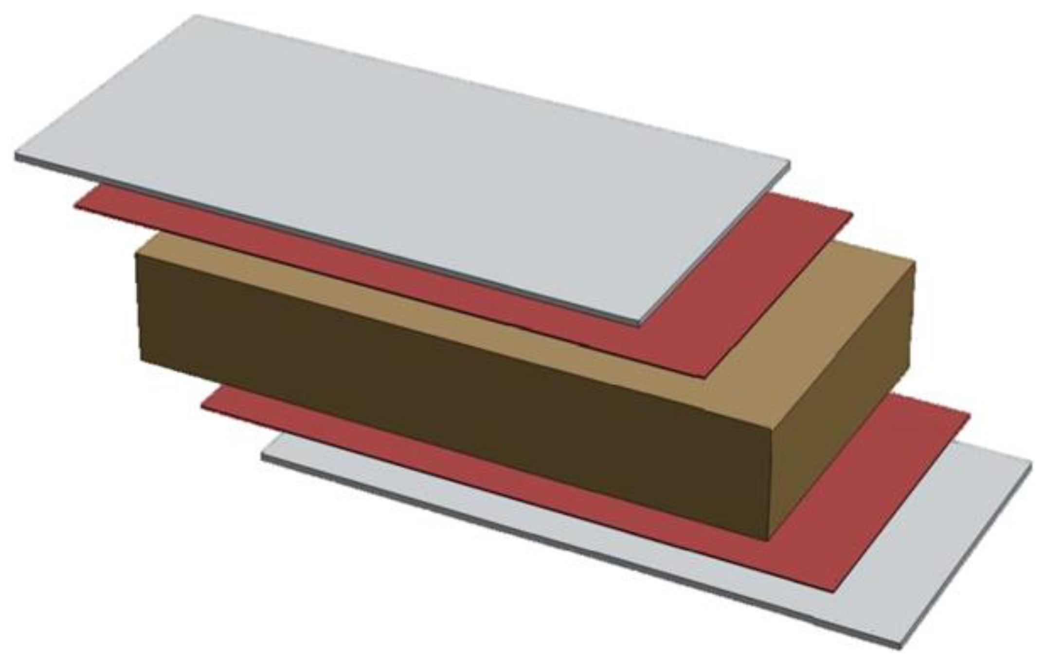
These structures are composed by at least three layers: two relatively thin ones characterized by high stiffness and mechanical strength, known as skins, and an inner one known as core. The latter is a thick layer of a less dense material, characterized by lower stiffness and mechanical strength. Figure 1 presents an illustration of these layers as well as the adhesive responsible for binding them. Although a typical sandwich is composed by three layers and two materials, there are complex structures where the core and even the skins are composed by two or more materials [2].
The skins must have a good tensile and compressive strength and designed to be subjected to bending loads. On the other hand, the core must be designed with enough strength to be subjected to shear loads caused by tensile and compressive loads acting on the skins. The adhesive is the binding agent, spreading the loads between layers. By binding these with an adhesive, it gives a significant stiffness and strength to the overall structure. It needs to be compatible with the materials of both skins and core in order to bind them successfully [3].
The skins need materials with a high mechanical strength. The skins, depending on the application, are also subjected to different external attacks such as impacts, humidity, fire, corrosion, etc. Metals such as stainless steels and aluminum alloys are usually good options, being cheap due to mass production. Regarding non-metallic materials, wood laminated panels are also a low-cost solution, presenting a lower density than metals and being easier to manufacturer in complex shapes. However, these are more prone to several types of damage caused for example by water or fire.
Currently, there is a great interest on composite skins, resulting from a combination between a matrix based on resins such as polyester, epoxy, vinyl ester, phenolics [4,5,6,7], and fibers such as fiber glass, carbon fiber aramid fibers and even plant fibers [3,6,8,9], among many others. Glass fibers are among the most common, mainly due to its good mechanical properties, low-cost, and weight. Although carbon fiber has a much superior mechanical strength, it is also much more expensive. More recently, in order to improve the impact resistance of foam core sandwich panels and to protect the foam core, superelastic shape memory alloy (SMAs) wires were incorporated into the face sheets of foam core sandwich panels [10].
Core materials are subjected to shear loads and compression loads in the sandwich structure, examples of these materials and structures, depending on the application, are metal or polymeric foams, honeycomb structures, cork, and even corrugated cores [11,12,13,14,15,16,17]. Foams are characterized by low densities, from polymeric foams such as polyvinyl chloride (PVC), polymethacrylimide (PMI), expanded polystyrene (EPS), and polyurethane (PU) to phenolic resin-based foams. The latter have good structural/thermal performance and are a low-cost solution. Considering honeycomb structures, these can be made from aluminum alloys to Kevlar paper-based honeycomb cores [18]. This type of core presents a higher specific stiffness and specific compressive strength but are poor insulators. More recently, Shi et al., [19], combined honeycomb cores and grid cores, resulting in an honeycomb—grid hybrid core. This parametric study indicated that core thickness has the most significant influence on the specific bending stiffness. On the other hand, the specific in-plane stiffness of sandwich panels was mostly dependent on the grid spacing. Another example of hybrid cores is the one presented by Jayaram et al., [20], testing polyester pin-reinforced foam filled honeycomb sandwich panels against traditional nonreinforced ones. The impact response was greatly improved.
Regarding the adhesive material, this one must have similar or even better mechanical properties than the core material. The failure of the sandwich panel must not be due to failure of adhesive joints, thus, debonding is not admissible [21,22,23]. Within the wide set of adhesive options, PU glues are the most commonly used in quantities ranging from 200 to 350 g/m2. The cure of the adhesive is also an important aspect, where humidity, pressure and temperature are important variables [24,25,26,27,28]. Additionally, in the case of adhesives with two components, the mixing is carried out in the moment of application, usually between a base resin (polyol) and a curing agent (isocyanate). With this type of adhesives, the curing time under pressure can be controlled not only through the quantity ratio but also with heat. There are also solid adhesive films that are thermally activated, which do not depend on the experience of the person mixing as in the case of glues with two components, eliminate glue waste, and the properties are which are guaranteed by the manufacturer [29,30].
The study of failure mechanisms in sandwich composite structures is of high importance in order to determine the performance of these structures, especially in very specific applications. Thus, design tools that can consider and predict these failure mechanisms are needed. Recently, Funari et al., [31,32], presented numerical models based on Arbitrary Lagrangian-Eulerian formulation capable to predict crack propagation in sandwich structures and debonding mechanisms respectively.
One of the most important factors in the manufacturing of honeycomb-cored sandwich structures is the effective application of the adhesive in order to guarantee a good strength. The main problem of honeycomb cores is the low contact area with the skins, which might lead to excessive forces on the core’s cell edges bound to the skins. The typical approach to solve this problem is to place the adhesive on the membrane and not on the core. Nevertheless, still more than 90% of the adhesive is not in contact with the core’s cell structure. In the case of adhesive glues this leads to a waste of material in the core, which also decreases the resistance to fire even in aluminium honeycombs.
The aim of this work is to manufacture sandwich panels to be used in interactive boards. To solve the adhesive issue, an advanced adhesive film applied directly on the core’s cell edges was used, instead of applying it on the skins. This resulted on savings of the amount of adhesive up to 50% and on a sandwich paned with increased the strength by 3 to 5 times. The skins used were steel and ceramic sheets. The core used was polypropylene (PP) honeycombs due to its good applicability in static applications considering its excellent weight/strength ratio. The performance of this type of sandwich was compared against a typical one available on the market. These samples were manufactured in an automated laminating line and then subjected to three-point flexural tests.
2. Materials and Methods
The core used was PP honeycomb, considering its excellent weight/strength ratio and applicability in static applications. PP honeycombs have a density between 60 and 120 kg/m3. Regarding the skins, the frontal membrane was 0.35 mm thick PolyVision e3 CeramicSteel sheet. The opposite skin was a 0.25 mm thick sheet of galvanized steel DX51D. In order to successfully assemble these parts into one unique structure, a polyolefin adhesive film (ref. 22.001—collano®) was used. Table 1 presents the sequential order of the layers for the new sandwich panel solution and a typical one available on the market. The first layer corresponds to the frontal layer of the board. The final samples of sandwich 1 and sandwich 2 have 9 mm and 22 mm, respectively.
2.1. Adhesive Film and Bonding Technique
One of the most important factors in the manufacturing of honeycomb-cored sandwich structures is the effective application of the adhesive. There is low contact area between cores and the skins, which might result in excessive forces on the cells edges bound to the skins.
The typical approach to solve this issue is to place the adhesive on the membrane and not on the core. Nevertheless, still more than 90% of the adhesive is not in contact with the cells structure. In the case of adhesive glues, this leads to a waste of material. To solve this issue, an adhesive developed by Collanno® was applied directly on the core’s cell edges, leading to an optimized used of the adhesive, saving 50% of the adhesive and increasing the strength of the sandwich paned by 3 to 5 times [33].
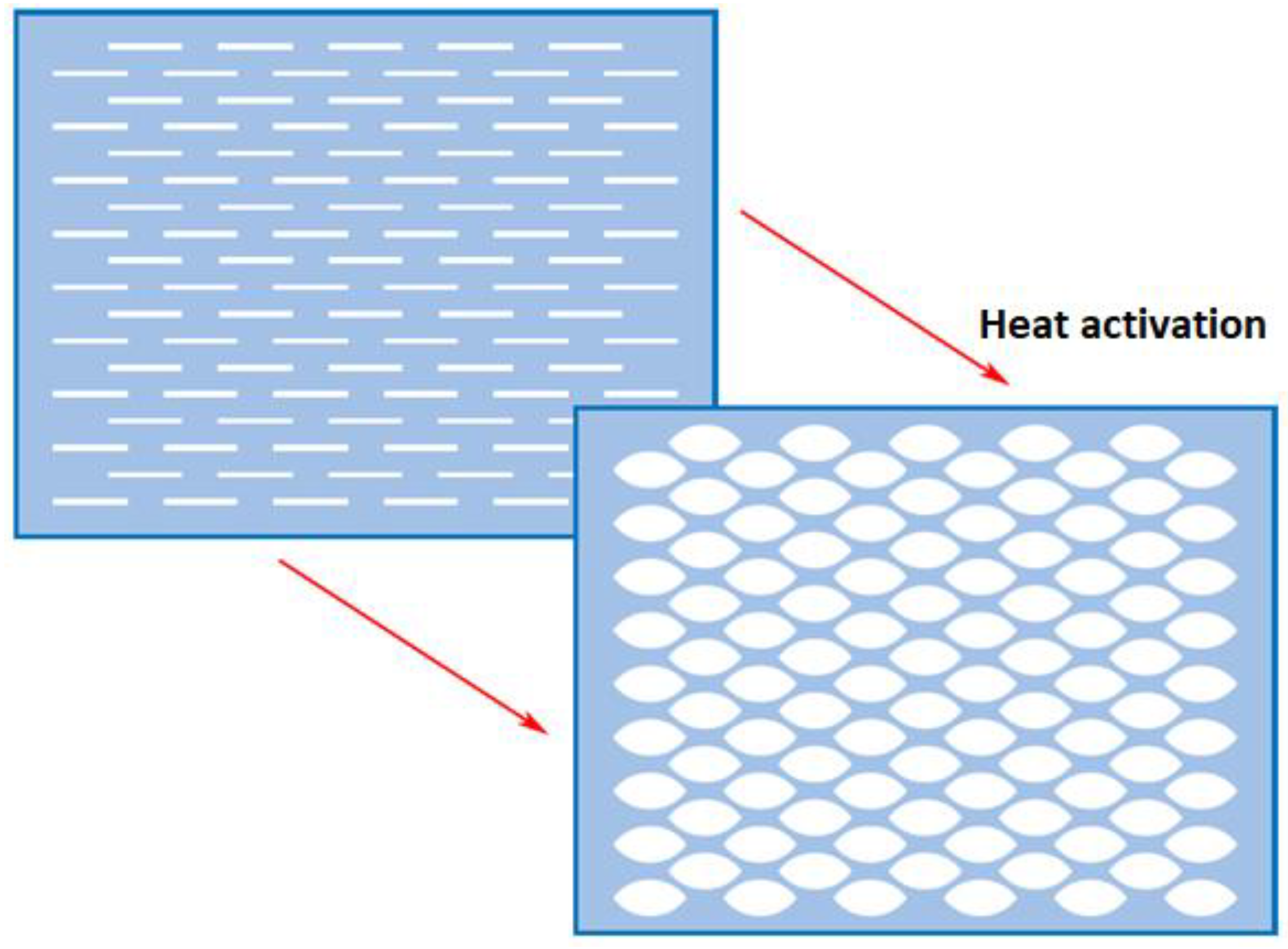
This solution is an advanced adhesive film with a slit thermally sensitive pattern. Figure 2 presents an illustration of the thermally activated adhesive net. When the adhesive is heated, due to its thermally dependent viscous state, the film’s structure fits the core’s cell edges, bonding both together. In order to ensure a good bonding between this adhesive net and the honeycomb cell edges:
- The film must be placed on the honeycomb without any restraint, just simply place on it.
- The film must be biaxially stretched in order to get a well distribution by the polymer molecules.
- The film must have a suitable slit pattern considering the honeycomb structure in order to adapt to it.
The adhesive film employed in this work is linear low-density polyethylene (LLDPE) chemically based, with a melting temperature ranging from 115 to 130 °C and a minimal bond line temperature of 130 °C. This adhesive film has a melt flow index, according to DIN 53735 standard (190 °C; 21.2 N), between 3 and 8 g per 10 min and presents an open time up to 2 s. Other important properties are presented in Table 2.
The manufacturing conditions, such as pressing time, temperature, and pressure, are extremely important to the final properties of the sandwich structure. The conditions used were the ones indicated in [33], which are summarized in Table 3. This is the best set of conditions to obtain the higher strength.
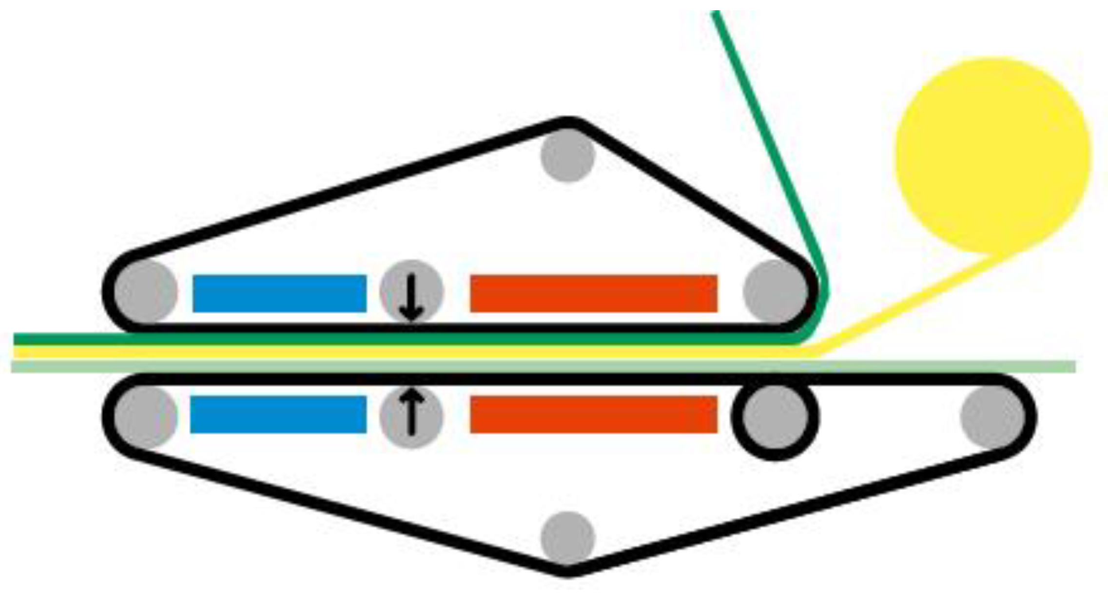
In order to manufacture the sandwich panels for interactive boards with this new technology, an industrial equipment was developed. Figure 3 presents and illustration on how the manufacturing process works. This process is based on the hypothesis that by embedding the honeycomb edge in the precoated adhesive, better results are yielded.
This automated laminating line, the model Elytra from Tebulo, is composed by
- Adhesive unwinder;
- Tabletop laminator with temperature control;
- Automatic adjustable pressure system after passing the heating zone;
- Cooling zone in order to obtain smooth surfaces;
- Separated heating and cooling zones in the same machine;
- Seamless polyamide conveyor belts for bidirectional transport; and
- Industrial computer to control the entire production line.
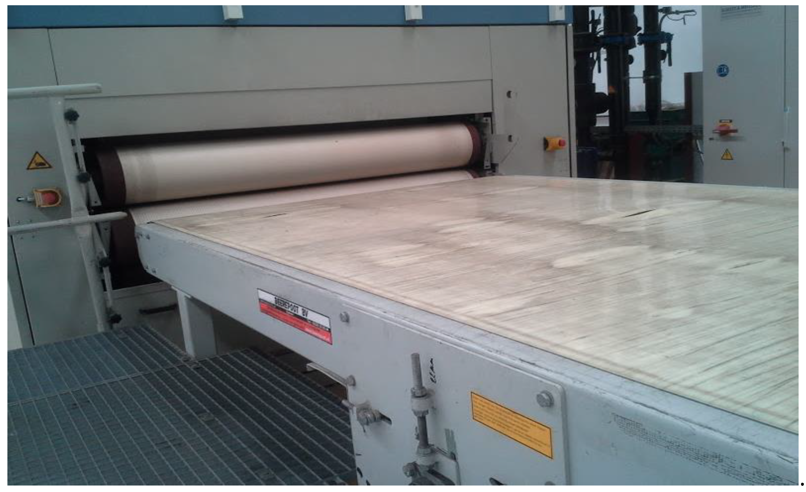
Bidirectional conveyor belts are a major key enabler in the application of the adhesive. In addition, the high level of temperature control due to the combination of heating and cooling systems, makes it possible to have a high degree of control over thermal deformations. Figure 4 presents the end of the manufacturing process, showing the sandwich panel’s output.
2.2. Bending Tests
In order to characterize the sandwich panel, three-point bending tests were performed on the manufactured boards. These are subjected to this type of loading in their real work environment. A universal testing machine Shimadzu 10 kN (Shimadzu, Kyoto, Japan) was used to carry testing according to ASTM C 393 standard at 6 mm/min. The diameter of the support pins is 4 mm, while the diameters of the two loading pins used are 10 mm and 40 mm. The length of the support span was 200 mm. ASTM C 393 standard test methodology is appropriate for cored sandwich structures under flexure loading and shear of the core is expected. For instance, as indicated by the standard, permissible core material forms include those with continuous bonding surfaces (such as balsa wood and foams) as well as those with discontinuous bonding surfaces (such as honeycomb) [34].
Regarding sandwich 1, sandwich panels from different lots were cut into samples, designated cn (n is the sample number, and thus ranges from 1 to 5), with a size of 300 mm × 40 mm, where the longitudinal direction corresponds to the lamination direction. Samples c1 and c2 were tested with the 10 mm loading pin. In order to test the samples to higher bending loads and to reduce the probability of concentrated failure in the loading point, the 40 mm pin was used to test samples c3 to c5. And it is possible to observe that failure is not localized as it was in the previous tests. Additionally, in order to verify the loading side influence, since the sandwich panels are not symmetrically due to the different skins, c4 and c5 were tested on the opposite skin.
Regarding sandwich 2, sandwich panels from different lots were cut into samples, designated can (n is the sample number, and thus ranges from 1 to 4), in the same size of samples from sandwich 1. Once sandwich 2 has 22 mm, the 10 mm loading pin was not used, since the main aim is to evaluate the bonding strength between the different glued layers. The first two bending tests, ca1–2, were tested on the posterior side with a 40 mm loading pin, while samples ca3–4 were tested on the anterior skin.
3. Results
3.1. Sandwich 1—PP Honeycomb Core Panels with Advanced Adhesive Film
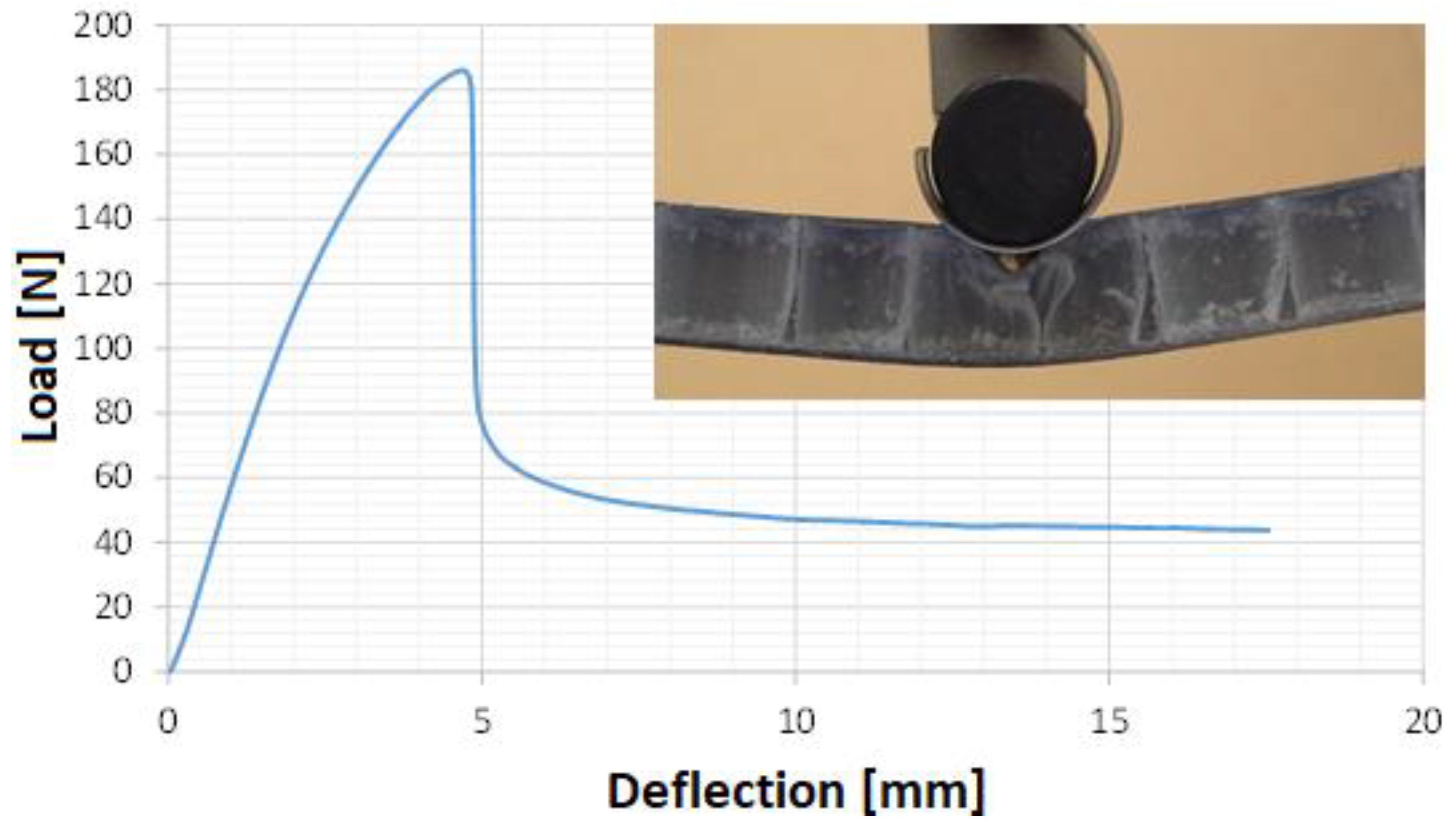
Figure 5, Figure 6 and Figure 7 show sample c1 prior testing, the same sample being tested, and the load vs. mid-span deflection, respectively, measured during the bending test. The later also sows the failure of the structure, probably caused by the loading pin indentation being aligned with load.
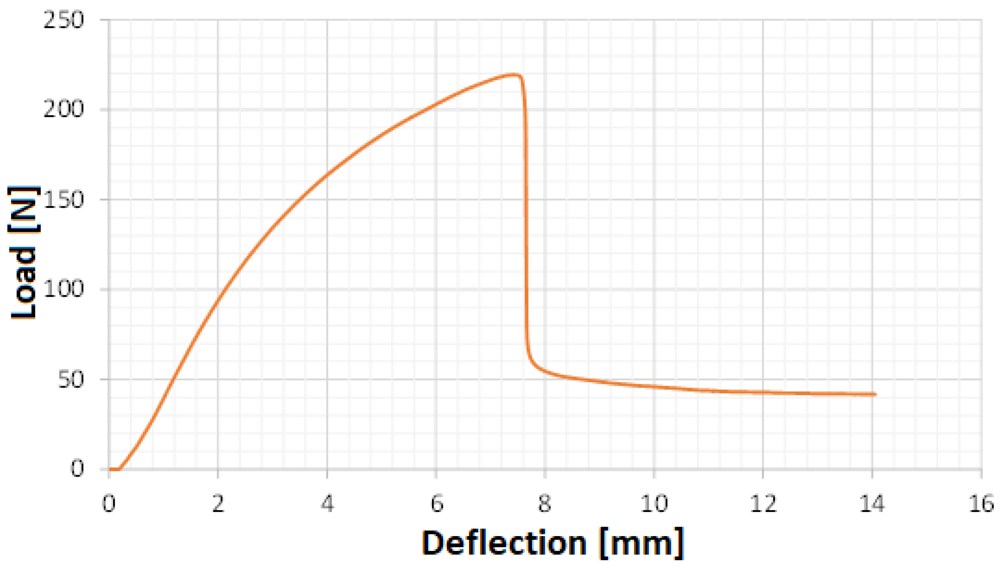
Sample c2 was tested with the same conditions as sample c1. Figure 8 and Figure 9 present the load vs. mid-span deflection measured during the bending test and the failure modes, respectively. There is no debonding between the layers. Again, the critical deformation is purely on the skin where the load is applied.
This type of failure was expected due to the low diameter of the loading pin used and the potential stress concentration. Nevertheless, it was important to determine the occurrence of layer debonding, for lower and concentrated loads. The results obtained with samples c1 and c2 revealed that there is an excellent bond between core and skins, thanks to new manufacturing methodology and advanced adhesive film employed.
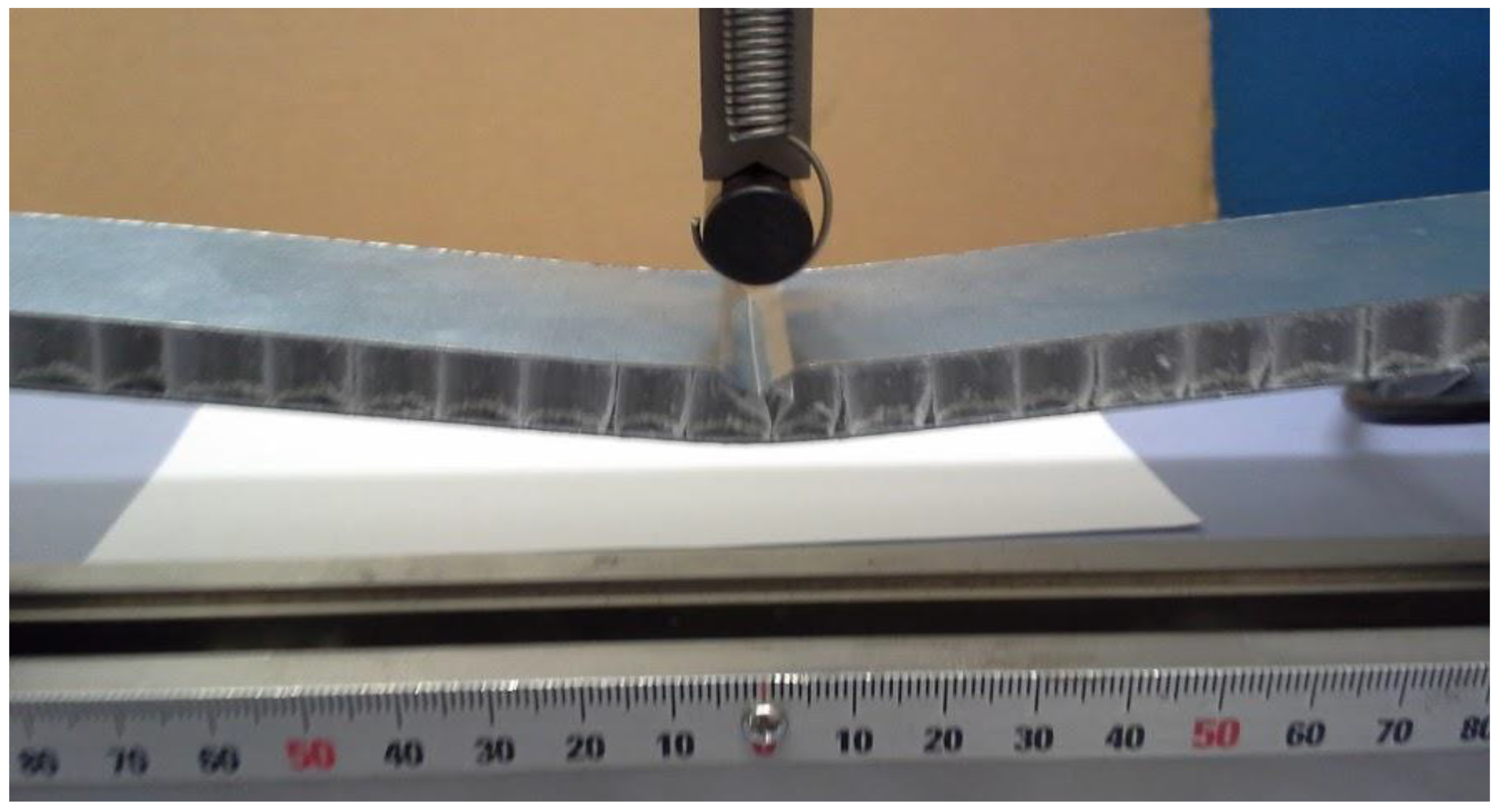
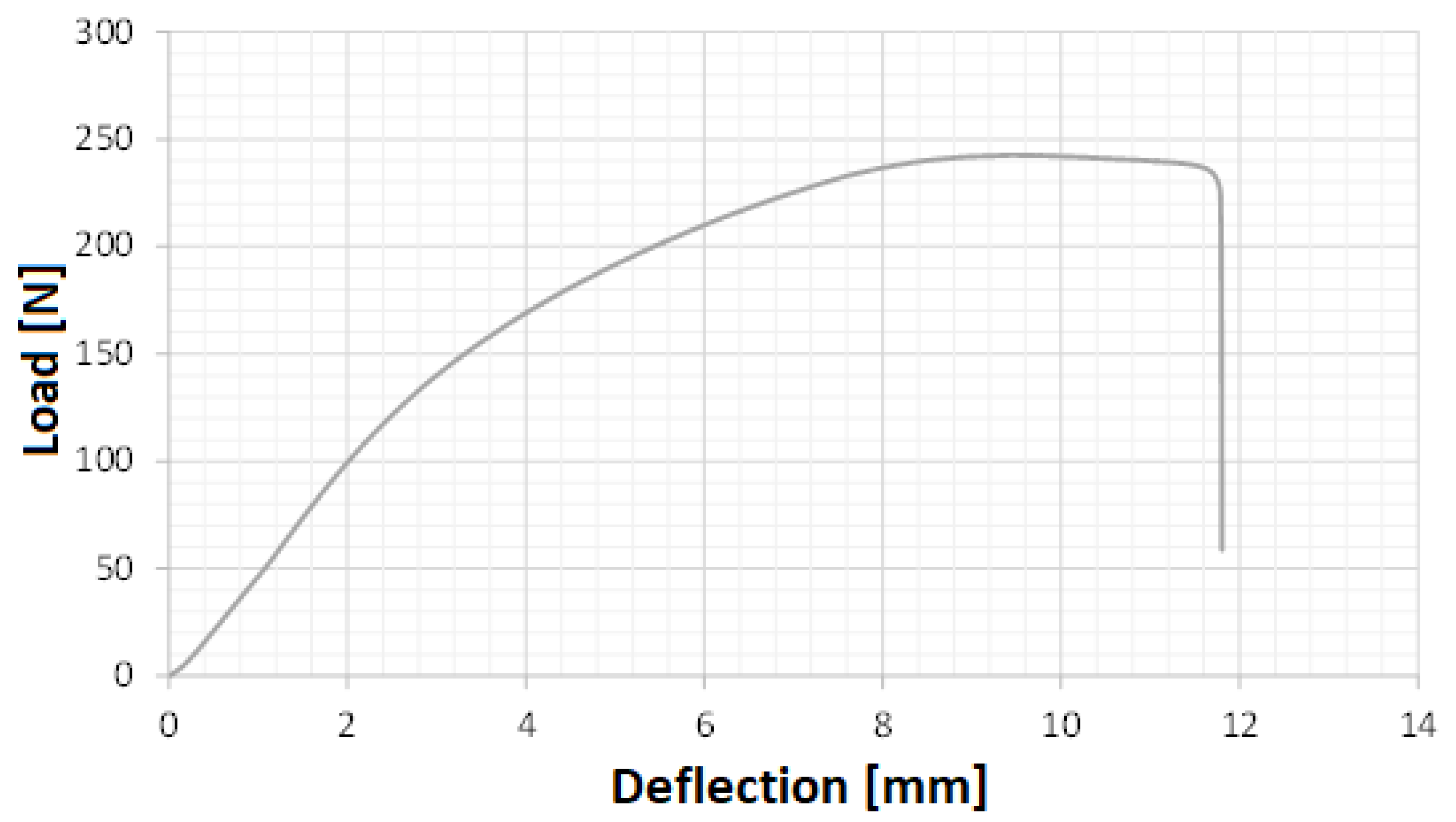
In order to increase the bending load and to reduce the probability of concentrated failure in the loading point, a loading tool with a higher diameter was used. Figure 10 shows sample c3 after testing with the 40 mm pin, and it is possible to observe that failure is not localized as it was in the previous tests. Figure 11 presents the load vs. mid-span deflection measured during the bending test. As expected, the energy absorption was much higher than in the previous tests.
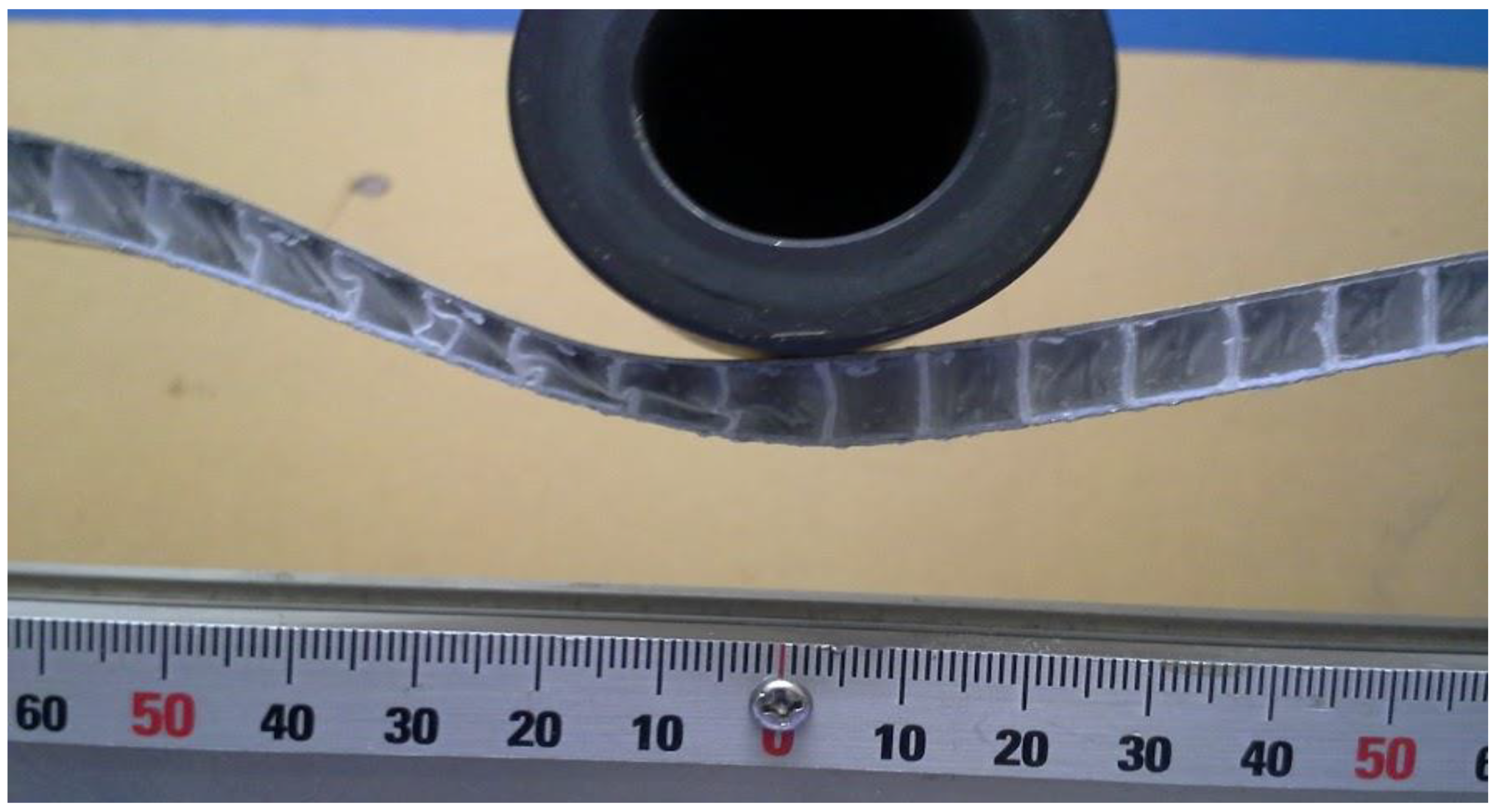
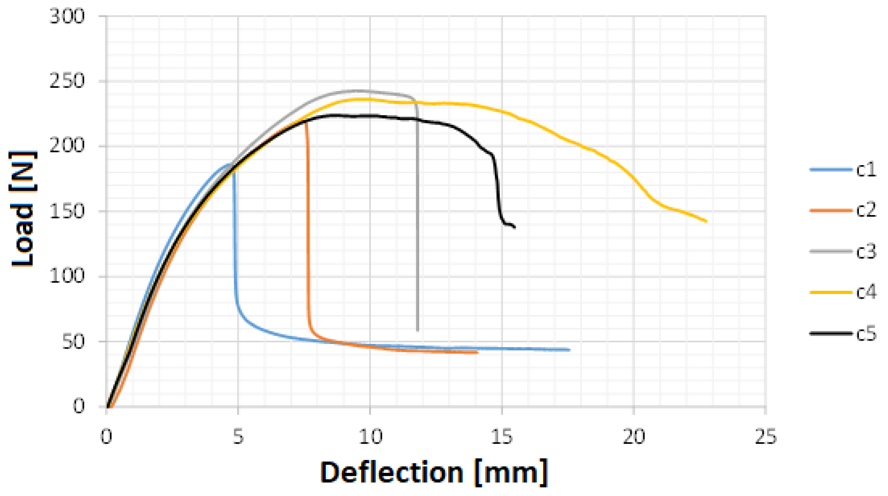
Figure 12 presents sample c4 after testing, which was loaded on the opposite skin. Again, no debonding was observed, verifying an excellent performance by the adhesive film. Additionally, no failure was verified, just normal curvature due to the deflection imposed. It is worthy to mention that these levels of deflections are much higher than the typical ones that commonly occur in real life with boards. Nevertheless, this guarantees a high performance by the board in extreme cases such as accidents or abnormal situations. Figure 13 presents the load vs. mid-span deflection measured during the bending test for both c4 and c5, together with the previous tested samples of sandwich 1. The behavior of samples c4 and c5 is very similar to the one of sample c3, which makes it possible to conclude that the sandwich 1 mechanical behavior under bending load is independent of the skin where it is applied.
3.2. Sandwich 2—Cardboard Honeycomb Core Panels Reinforced with MDF
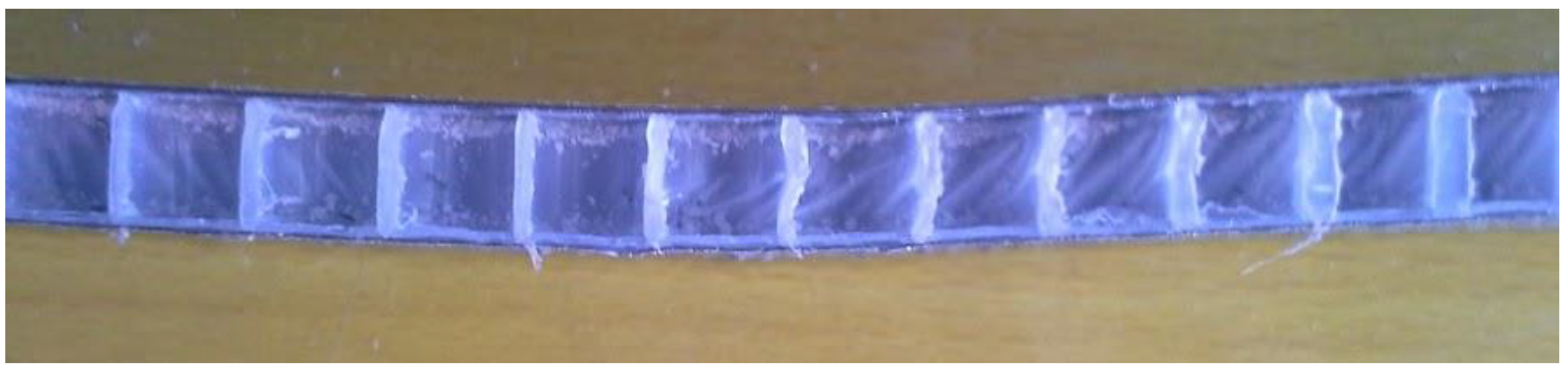
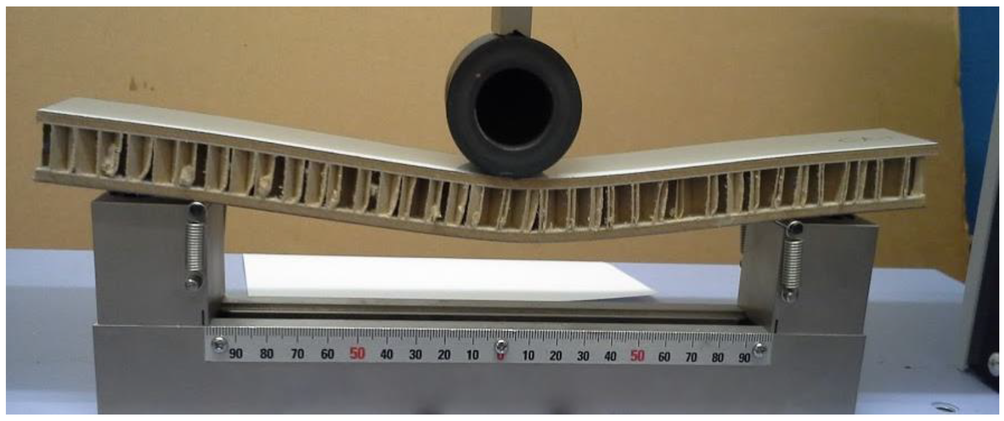
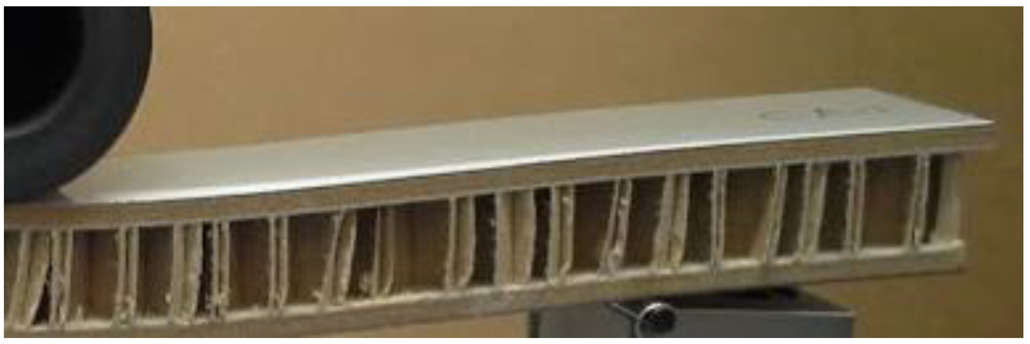
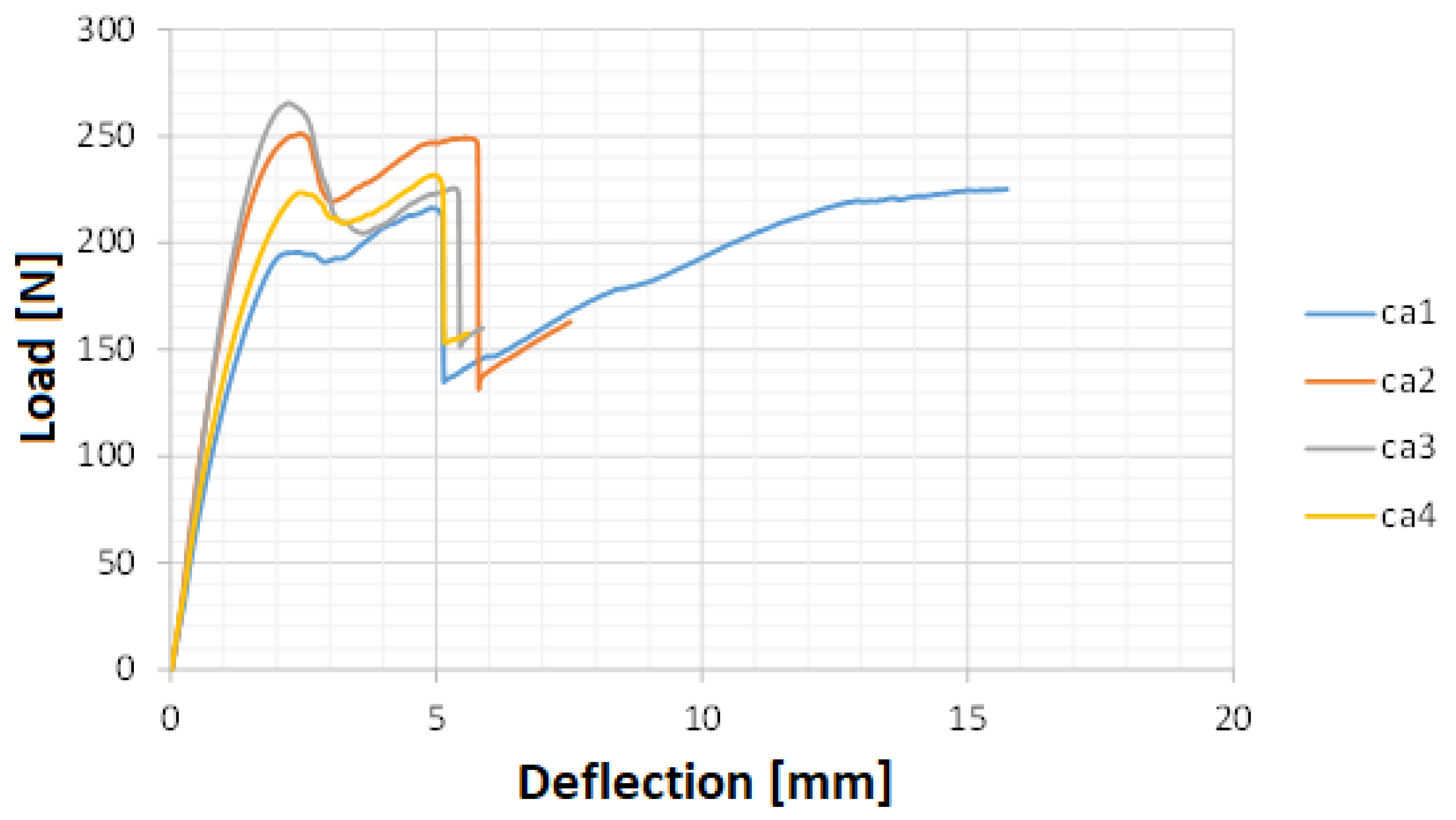
Figure 14 shows the bending test of sample ca1 at the moment of maximum loading. Contrarily to samples from sandwich 1, debonding was observed in samples ca1 and ca2, resulting in delamination. In Figure 15, it is possible to verify closely the delamination, showing a clearly different failure mode from sandwich 1. Nevertheless, as plotted in Figure 16, the maximum load supported by sandwich 2 is at the same level of sandwich 1. The results obtained with the samples tested on the frontal skin were similar to ca1–2 samples. Figure 16 shows a similar behavior between samples ca1–4, resulting in maximum loads between 190 and 275 N, similarly to the values obtained with sandwich 1.
Overall, the flexural behavior of the sandwiches can be divided in three distinct regions. Until approximately 2 mm, there is a linear increase of the load related to the linear elastic region. Within approximately 2 mm and 4.7 mm, the increase of the load-displacement curve curvature is justified by the elastoplastic behavior (indentation by the loading tool). At 4.7 mm, the top skin is ruptured as well as part of the core in neighboring regions. From approximately 4.7 to 10 mm, the core is crushed, reducing its thickness and creating more cracks across it and thus, lowering the overall strength of the structure. Between 10 and 20 mm (the total failure is not at 20 mm), the load always decreased until the core was completely crushed, which could actually result in an increase of the load, since the core is completely compressed.
3.3. Summary
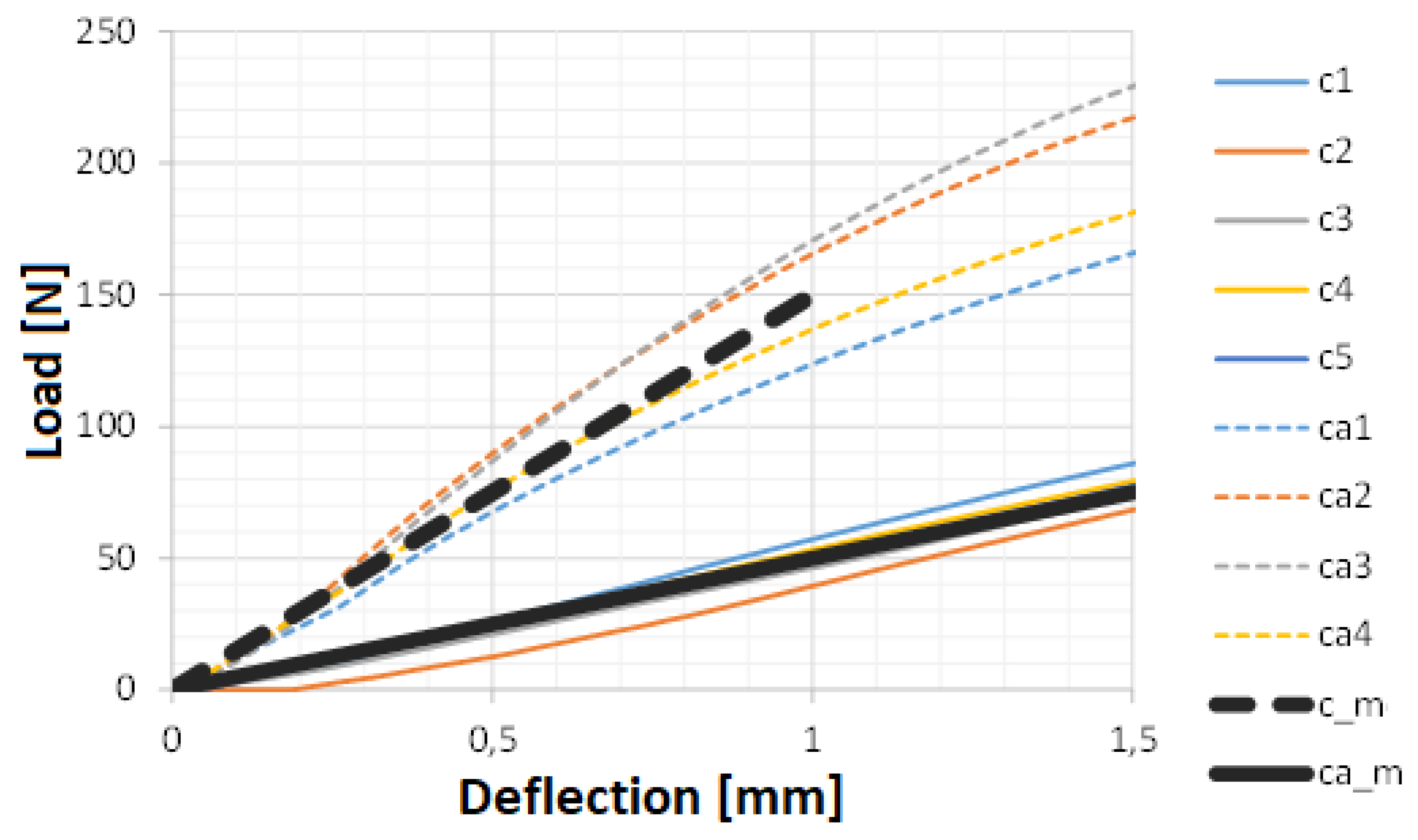
The results presented for both types of sandwich, make it possible to predict which has higher stiffness and mechanical strength. Figure 17 presents the elastic region for both sandwiches, as well as the mean values for each type. This direct comparison makes it is possible to conclude that sandwich 2 presents a much higher stiffness (300%) than sandwich 1, although both withstand the same load level. Additionally, the delamination damaged caused by debonding of the layers was only seen in samples of sandwich 2, which makes it possible to conclude that the adhesive film was employed successfully. Table 4 presents the mean stiffness and bending flexibility.
Considering both types of sandwich, the higher stiffness was reached by sandwich 2, reaching a stiffness of 170 N/mm, while the stiffer sandwich 1 presented a stiffness value of 58 N/mm. On the other hand, the higher flexibility obtained with sandwich 1 was 0.0081 mm/N, while the highest flexibility was obtained with sandwich 2, a value of 0.022 mm/N.
4. Conclusions
In this work, an automated laminating line was successfully used to manufacture sandwich panels with an innovative adhesive solution. An advanced solid film was employed with success, saving material and no debonding was seen in the three-point bending tests. Delamination was only observed in sandwich samples, which layers were glued with a liquid adhesive, a typical sandwich used to manufacture boards already available on the market. Although it was seen in the experiments that a much higher stiffness is reached by the typical solution, the load level reached with both types was similar. Additionally, the thickness of sandwich 2 is much higher, 22 mm against the 9 mm from sandwich 1. Therefore, this innovative technology makes it possible to manufacture thinner boards, reducing the amount of materials employed, including the adhesive. The main aim of the study was successfully accomplished, since delamination damaged caused by debonding of the layers was only seen in sandwich 2.
Author Contributions
Conceptualization, A.B.P. and F.A.O.F.; methodology, A.B.P. and F.A.O.F.; software, A.B.P. and F.A.O.F.; validation, A.B.P. and F.A.O.F.; formal analysis, A.B.P. and F.A.O.F.; investigation, A.B.P. and F.A.O.F.; resources, A.B.P. and F.A.O.F.; data curation, A.B.P. and F.A.O.F.; writing—original draft preparation, A.B.P. and F.A.O.F.; writing—review and editing, A.B.P. and F.A.O.F.; visualization, A.B.P. and F.A.O.F.; supervision, A.B.P. and F.A.O.F.; project administration, A.B.P. and F.A.O.F.; funding acquisition, A.B.P. and F.A.O.F.
Funding
UID/EMS/00481/2019-FCT-FCT-Fundação para a Ciencia e a Tecnologia; and CENTRO-01-0145-FEDER-022083-Centro Portugal Regional Operational Programme (Centro2020), under the PORTUGAL 2020 Partnership Agreement, through the European Regional Development Fund.
Acknowledgments
Center for Mechanical Technology and Automation; and Fundação para a Ciência e a Tecnologia: researcher under grant CEECIND/01192/2017.
Conflicts of Interest
The authors declare no conflicts of interest.
References
- Lindström, A.; Hallström, S. In-plane Compression of Sandwich Panels with Debonds. Compos. Struct. 2010, 92, 532–540. [Google Scholar] [CrossRef]
- Hami, B.; Irekti, A.; Aribi, C.; Bezzazi, B.; Mir, A. Experimental Study of Sandwich Multilayer Reinforced by Glass Fibre and Agglomerated Cork. Adv. Compos. Lett. 2014, 23, 121–125. [Google Scholar] [CrossRef]
- Mohareb, A.S.O.; Hassanin, A.H.; Badr, A.A.; Hassan, K.T.S.; Farag, R. Novel Composite Sandwich Structure from Green Materials: Mechanical, Physical, and Biological Evaluation. J. Appl. Polym. Sci. 2015, 132, 42253. [Google Scholar] [CrossRef]
- Bader, S. Composites Handbook; Scott Bader Company Limited: Wollaston, England, 2002; pp. 1–90. [Google Scholar]
- Kandola, B.K.; Ebdon, J.R.; Zhou, C. Development of Vinyl Ester Resins with Improved Flame Retardant Properties for Structural Marine Applications. React. Funct. Polym. 2018, 129, 111–122. [Google Scholar] [CrossRef]
- Fernandes, F.A.O.; Tavares, J.P.; Alves de Sousa, R.J.; Pereira, A.B.; Esteves, J.L. Manufacturing and Testing Composites Based on Natural Materials. Procedia Manuf. 2017, 13, 227–234. [Google Scholar] [CrossRef]
- Kandola, B.K.; Krishnan, L.; Deli, D.; Luangtriratana, P.; Ebdon, J.R. Fire and Mechanical Properties of a Novel Free-Radically Cured Phenolic Resin Based on a Methacrylate—Functional Novolac and of its Blends with an Unsaturated Polyester Resin. RSC Adv. 2015, 5, 33772–33785. [Google Scholar] [CrossRef]
- Sarasini, F.; Tirillò, J.; Ferrante, L.; Sergi, C.; Russo, P.; Simeoli, G.; Cimino, F.; Ricciardi, M.R.; Antonucci, V. Quasi-Static and Low-Velocity Impact Behavior of Intraply Hybrid Flax/Basalt Composites. Fibers 2019, 7, 26. [Google Scholar] [CrossRef]
- Herráez, M.; Fernández, A.; Lopes, C.S.; González, C. Strength and Toughness of Structural Fibres for Composite Material Reinforcement. Philos. Trans. R. Soc. A Math. Phys. Eng. Sci. 2016, 374, 20150274. [Google Scholar] [CrossRef]
- Li, H.; Wang, Z.; Yu, Z.; Sun, M.; Liu, Y. The Low Velocity Impact Response of Foam Core Sandwich Panels with a Shape Memory Alloy Hybrid Face-Sheet. Materials 2018, 11, 2076. [Google Scholar] [CrossRef]
- Kaczyński, P.; Ptak, M.; Fernandes, F.A.O.; Chybowski, L.; Wilhelm, J.; Alves de Sousa, R.J. Development and Testing of Advanced Cork Composite Sandwiches for Energy-Absorbing Structures. Materials 2019, 12, 697. [Google Scholar] [CrossRef]
- Kazemahvazi, S.; Kiele, J.; Russel, B.; Deshpande, V.; Zenkert, D. Impact Properties of Corrugated Composite Sandwich Cores. In Proceedings of the 9th International Conference on Sandwich Structures. Caltech University, Pasadena, CA, USA, 14–16 June 2010. [Google Scholar]
- Zhang, Y.C.; Zhang, S.L.; Wang, Z.L. Crush Behavior of Corrugated Cores Sandwich Panels. Adv. Mater. Res. 2011, 217–218, 1584–1589. [Google Scholar] [CrossRef]
- Russell, B.P.; Malcom, A.; Wadley, H.N.G.; Deshpande, V.S. Dynamic Compressive Response of Composite Corrugated Cores. J. Mech. Mater. Struct. 2010, 5, 477–493. [Google Scholar] [CrossRef]
- Ptak, M.; Kaczyński, P.; Fernandes, F.; De Sousa, R.A. Computer Simulations for Head Injuries Verification after Impact. In Lecture Notes in Mechanical Engineering; Springer: Berlin, Germany, 2017; pp. 431–440. [Google Scholar]
- Ptak, M.; Wilhelm, J.; Sawicki, M. Safety Analysis of Children Transported on Bicycle-Mounted Seat During Traffic Accidents. Int. J. Crashworthiness. 2019, in press. [Google Scholar] [CrossRef]
- Fernandes, F.A.O.; Alves de Sousa, R.; Ptak, M.; Migueis, G. Helmet Design Based on the Optimization of Biocomposite Energy-Absorbing Liners under Multi-Impact Loading. Appl. Sci. 2019, 9, 735. [Google Scholar] [CrossRef]
- Saseendran, V.; Berggreen, C. Mixed-Mode Fracture Evaluation of Aerospace Grade Honeycomb Core Sandwich Specimens using the Double Cantilever Beam–Uneven Bending Moment Test Method. J. Sandwich Struct. Mater. 2018, in press. [Google Scholar] [CrossRef]
- Shi, S.; Chen, B.; Sun, Z. Equivalent Properties of Composite Sandwich Panels with Honeycomb–Grid Hybrid Core. J. Sandwich Struct. Mater. 2018, in press. [Google Scholar] [CrossRef]
- Jayaram, R.; Nagarajan, V.; Kumar, K.V. Compression and Low Velocity Impact Response of Sandwich Panels with Polyester Pin-Reinforced Foam Filled Honeycomb Core. J. Sandwich Struct. Mater. 2018, in press. [Google Scholar] [CrossRef]
- Odessa, I.; Frostig, Y.; Rabinovitch, O. Modeling of Interfacial Debonding Propagation in Sandwich Panels. Int. J. Solids Struct. 2018, 148–149, 67–78. [Google Scholar] [CrossRef]
- Li, H.; Zhou, Z. Detection and Characterization of Debonding Defects in Aeronautical Honeycomb Sandwich Composites Using Noncontact Air-Coupled Ultrasonic Testing Technique. Appl. Sci. 2019, 9, 283. [Google Scholar] [CrossRef]
- Funari, M.F.; Greco, F.; Lonetti, P. Sandwich Panels under Interfacial Debonding Mechanisms. Compos. Struct. 2018, 203, 310–320. [Google Scholar] [CrossRef]
- Lee, L.H. Adhesive Bonding. In Handbook of Plastics Joining, 2nd ed.; William Andrew: Norwich, UK, 2009; pp. 145–173. [Google Scholar]
- Davis, M.; Bond, D. Principles and Practices of Adhesive Bonded Structural Joints and Repairs. Int. J. Adhes. Adhes. 1999, 19, 91–105. [Google Scholar] [CrossRef]
- Ebnesajjad, S. Adhesive Applications and Bonding Processes. In Adhesives Technology Handbook, 2nd ed.; William Andrew: Norwich, UK, 2009; pp. 183–208. [Google Scholar]
- Gomes, G.M.F. Characterization and Optimization of the Production Process of Sandwich Composite Structures; Universidade de Lisboa: Lisbon, Portugal, 2016. [Google Scholar]
- Hussain, M.I.; Zain, Z.M.; Ying, C.J.; Sin, T.C. Effect of Humidity on Physical Properties of Prepreg and Adhesive Film of Composite Material Manufacturing. In Proceedings of the Sixth International Conference on Industrial Engineering and Operations Management, Kuala Lumpur, Malaysia, 8–10 March 2016. [Google Scholar]
- Bishopp, J. Adhesives for Aerospace Structures. In Handbook of Adhesives and Surface Preparation; William Andrew: Norwich, UK, 2011; pp. 301–344. [Google Scholar]
- Rider, A.N.; Arnott, D.R.; Mazza, J.J. Surface Treatment and Repair Bonding. In Aircraft Sustainment and Repair; Butterworth-Heinemann: Oxford, UK, 2018; pp. 253–323. [Google Scholar]
- Funari, M.; Greco, F.; Lonetti, P.; Spadea, S. A Numerical Model Based on ALE Formulation to Predict Crack Propagation in Sandwich Structures. Frat. ed Integrità Strutt. 2019, 47, 277–293. [Google Scholar] [CrossRef]
- Funari, M.F.; Greco, F.; Lonetti, P.; Luciano, R.; Penna, R. An Interface Approach Based on Moving Mesh and Cohesive Modeling in Z-Pinned Composite Laminates. Compos. Part B Eng. 2018, 135, 207–217. [Google Scholar] [CrossRef]
- Jud, K. Adhesive Films for the Production of Aluminium Honeycomb Panels; Collano Adhesives AG: Sempach Station, Switzerland, 2012. [Google Scholar]
- ASTM C393/C393M-16. Standard Test Method for Core Shear Properties of Sandwich Constructions by Beam Flexure; ASTM International: West Conshohocken, PA, USA, 2016. [Google Scholar]
Figure 1.
Basic sandwich panel composition: grey: skins; red: adhesive; brown: core.

Figure 2.
Heat effect on the adhesive film (adapted from [33]).
Figure 2.
Heat effect on the adhesive film (adapted from [33]).

Figure 3.
Illustration of the production line for manufacturing of sandwich panels, using slit adhesive films (adapted from [33]).
Figure 3.
Illustration of the production line for manufacturing of sandwich panels, using slit adhesive films (adapted from [33]).

Figure 4.
Sandwich panel’s output.

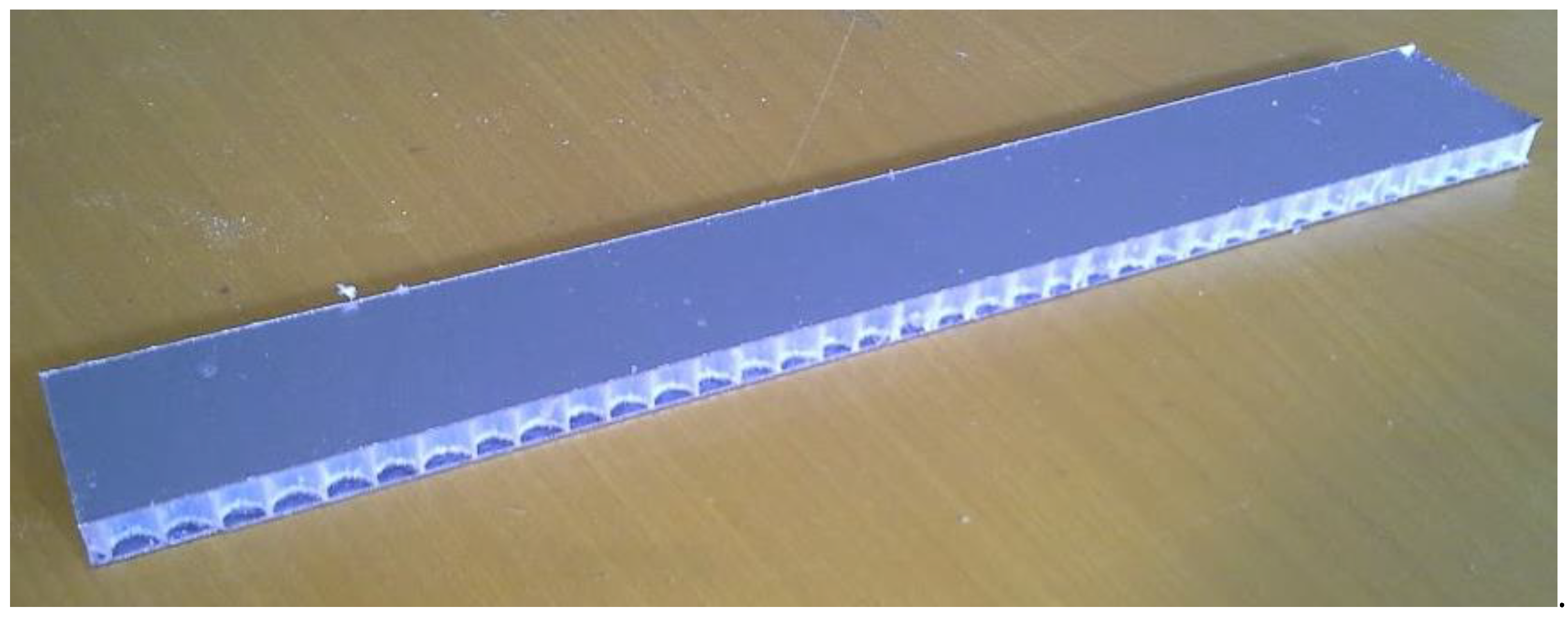
Figure 5.
Sample c1 prior testing.

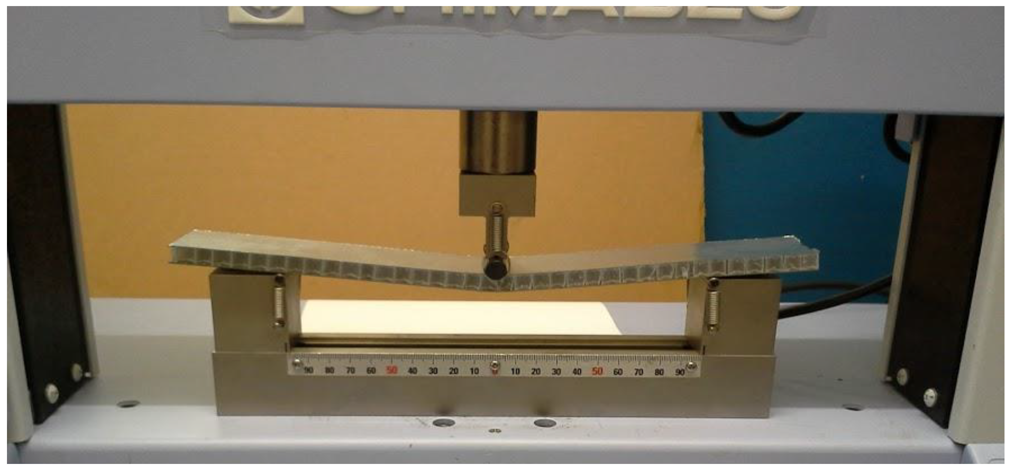
Figure 6.
Bending test of sample c1.

Figure 7.
Load vs. mid-span deflection measured during sample c1 testing. In the upper right corner shows the structure failure.
Figure 7.
Load vs. mid-span deflection measured during sample c1 testing. In the upper right corner shows the structure failure.

Figure 8.
Load vs. mid-span deflection measured during sample c2 testing.

Figure 9.
Bending test of sample c2 and failure detail.

Figure 10.
Bending test of sample c3 and failure detail.

Figure 11.
Load vs. mid-span deflection measured during sample c3 testing.

Figure 12.
Sample after tested on the opposite skin. No visual damage was observed.

Figure 13.
Load vs. mid-span deflection of sandwich panel 1.

Figure 14.
Bending test of sample ca1.

Figure 15.
Delamination of sample ca1.

Figure 16.
Load vs. mid-span deflection measured during testing of sandwich 2 samples.

Figure 17.
Elastic region: load vs. mid-span deflection measured for both types of sample (c_m and ca_m represent the respective mean values).
Figure 17.
Elastic region: load vs. mid-span deflection measured for both types of sample (c_m and ca_m represent the respective mean values).


Table 1.
Sequential order of the layers for the new sandwich panel solution and a typical one available on the market.
Table 1.
Sequential order of the layers for the new sandwich panel solution and a typical one available on the market.
| Layer | Sandwich 1 | Sandwich 2 |
|---|---|---|
| 1 | Ceramic sheet | Ceramic sheet |
| 2 | Adhesive film | Paper glue |
| 3 | PP honeycomb | MDF reinforcement |
| 4 | Adhesive film | Paper glue |
| 5 | Galvanized sheet | Cardboard honeycomb |
| 6 | Paper glue | |
| 7 | MDF reinforcement | |
| 8 | Paper glue | |
| 9 | Galvanized sheet |
Table 2.
Properties of the adhesive film Collano 22.001.
| Density (g/mL) | Shear Modulus (MPa) | Modulus of Elasticity (MPa) | Yield Stress (MPa) | Tensile Strength (MPa) | Ultimate Strain (%) |
|---|---|---|---|---|---|
| 0.9 | 60 | 115 | 3.8 | 14.1 | 1430 |
Table 3.
Manufacturing conditions [33].
Table 3.
Manufacturing conditions [33].
| Pressing Time (min) | Pressure (kPa) | Temperature (°C) |
|---|---|---|
| 3 | < 100 | 155 |
Table 4.
Mean values of stiffness and flexibility for both sandwiches.
| Sandwich | Flexibility (mm/N) | Stiffness (N/mm) |
|---|---|---|
| 1 | 0.02 | 50 |
| 2 | 0.007 | 150 |
© 2019 by the authors. Licensee MDPI, Basel, Switzerland. This article is an open access article distributed under the terms and conditions of the Creative Commons Attribution (CC BY) license (http://creativecommons.org/licenses/by/4.0/).
Share and Cite
MDPI and ACS Style
Pereira, A.B.; Fernandes, F.A.O. Sandwich Panels Bond with Advanced Adhesive Films. J. Compos. Sci. 2019, 3, 79. https://0-doi-org.brum.beds.ac.uk/10.3390/jcs3030079
AMA Style
Pereira AB, Fernandes FAO. Sandwich Panels Bond with Advanced Adhesive Films. Journal of Composites Science. 2019; 3(3):79. https://0-doi-org.brum.beds.ac.uk/10.3390/jcs3030079
Chicago/Turabian StylePereira, António Bastos, and Fábio A.O. Fernandes. 2019. "Sandwich Panels Bond with Advanced Adhesive Films" Journal of Composites Science 3, no. 3: 79. https://0-doi-org.brum.beds.ac.uk/10.3390/jcs3030079