Article

Composite Electrodes of Activated Carbon and Multiwall Carbon Nanotubes Decorated with Silver Nanoparticles for High Power Energy Storage

1
Department of Mechanical Engineering Sciences, University of Surrey, Guildford, Surrey GU2 7XH, UK
2
Institute of Nanoscience and Nanotechnology (INN), National Center of Scientific Research (NCSR) “Demokritos”, Agia Paraskevi Attikis, 153 41 Athens, Greece
*
Author to whom correspondence should be addressed.
Submission received: 7 October 2019 / Revised: 1 November 2019 / Accepted: 4 November 2019 / Published: 8 November 2019
(This article belongs to the Special Issue Feature Papers in Journal of Composites Science in 2019)

Abstract

:
Composite materials in electrodes for energy storage devices can combine different materials of high energy density, in terms of high specific surface area and pseudocapacitance, with materials of high power density, in terms of high electrical conductivity and features lowering the contact resistance between electrode and current collector. The present study investigates composite coatings as electrodes for supercapacitors with organic electrolyte 1.5 M TEABF4 in acetonitrile. The composite coatings contain high surface area activated carbon (AC) with only 0.15 wt% multiwall carbon nanotubes (MWCNTs) which, dispersed to their percolation limit, offer high conductivity. The focus of the investigations is on the decoration of MWCNTs with silver nanoparticles, where smaller Ag crystallites of 16.7 nm grew on carboxylic group-functionalized MWCNTs, MWCNT–COOH, against 27–32 nm Ag crystallites grown on unfunctionalized MWCNTs. All Ag-decorated MWCNTs eliminate the contact resistance between the composite electrode and the current collector that exists when undecorated MWCNTs are used in the composite electrodes. Ag-decorated MWCNT–COOH tripled the power density and Ag-decorated MWCNT additive doubled the power density and increased the maximum energy density by 6%, due to pseudocapacitance of Ag, compared to composite electrodes with undecorated MWCNTs.

1. Introduction

The theory of composite materials has infiltrated the energy storage devices, in the form of composite supercapacitor [1] and hybrid battery–supercapacitor devices [2,3]. Such devices contain composite electrodes and common electrolyte, where the composite electrode consists of materials with different properties that are mixed together or occupying different areas of the current collector, in which case they represent an in-parallel connection, or they are layered sequentially, in which case they represent an in-series connection. The current study focusses on electrode materials mixed together, in which case they experience a common potential as expected from the in-parallel connection with the current collector, with the electric current splitting between the two types of materials. For example, the design of a composite supercapacitor with composite electrodes targets a mixture of high power density materials and high energy density materials for the electrodes, with their composition designed so that the composite device offers a power-to-energy ratio as per the specification of a certain application [1].
Structural energy storage devices also target the structural performance of an assembly of composite materials by including the phase of a solid electrolyte possibly in epoxy matrix combined with a fibrous or coating-type porous electrode and a glass fiber separator [4,5,6,7]. Such devices may be fabricated using traditional composite manufacturing techniques, such as resin transfer molding (RTM) [8,9,10], vacuum-assisted RTM [11] or even structural reaction injection molding (SRIM) [12,13]. In terms of performance in energy storage, given the low ion diffusivity of the solid electrolyte, such materials exhibit high resistance to ion transport [14,15], ultimately also limiting their specific capacitance as the ions cannot reach the electrode walls within the available timescales. Reece et al. [16] designed a sulfur-crosslinked composite material to be used in the form of electrode coatings with some good mechanical properties to provide a solid supercapacitor, although of not very high modulus. In their study, the composite electrodes consisted of graphene as the main provider of high capacitance, carbon black and, in some cases, carbon nanotubes as high electrical conductivity additives, with the latter also improving mechanical performance and toughness, and sulfur which was used for crosslinking the graphene nanoplatelets and also offered a certain degree of pseudocapacitance contributing to the energy density.
High capacitance in electrochemical double layer capacitors (EDLCs) is provided by porous materials of large specific surface area, such as activated carbon (AC) [17], graphene and graphene oxide [18,19,20,21,22]. Carbon black [23,24] and multiwall carbon nanotubes (MWCNTs) [25,26,27,28] are commonly used to increase the electrical conductivity of composite coatings in supercapacitors [23,25,26,28] and batteries [24] or in composite interlayers between the electrode and current collector [29,30]. Furthermore, carbon nanotubes may be further functionalized to become compatible with the electrolyte solvent, such as –COOH functionalized MWCNTs to become hydrophilic for aqueous electrolytes [31] or compatible with polar electrolyte solvents such as acetonitrile [32] or patterned [33] to be compatible with the polymer binder used in the electrode coating, such as gelatin, polyvinyl alcohol (PVA) or PEDOT:PSS.
Certain materials have both high conductivity and offer pseudocapacitance, and as such they may increase both power and energy density, respectively. However, in order for the ions to be able to ingress in the material, such material needs to be thin or highly porous. For this reason, only a small amount of pseudocapacitive materials is typically used in composite electrodes. PEDOT:PSS is a conductive polymer [34,35] that when used as a binder has demonstrated pseudocapacitance contributions even in organic electrolytes [36]. Transition metal oxides, carbides and sulfides [37] also exhibit pseudocapacitance and some of them also enhance conductivity in composite electrodes to a certain extent, such as iron carbide [38]; however, it is difficult to homogeneously functionalize or decorate the main AC or graphene material with such compounds, as they tend to agglomerate.
Silver-decorated single wall carbon nanotubes (Ag-SWCNTs) exhibited Faradaic-type pseudocapacitance [37,39] in EDLCs with PVA/H3PO4 polymer electrolyte. Given also the high conductivity of silver pastes, the present study explores the decoration of conductive MWCNTs with Ag nanoparticles, and the addition of this highly conductive material to AC coatings to be tried as composite electrodes in EDLCs, where the high AC surface area provides the capacitance, possibly enhanced by any pseudocapacitance of Ag nanoparticles, while the Ag-decorated MWCNTs aim to raise the electrical conductivity in the EDLC. Given that aqueous electrolytes have a limited maximum voltage of 1.1 V, the organic electrolyte 1.5 M TEABF4 (tetraethylammonium tetrafluoroborate) in acetonitrile is employed in this study as it may reach 2.7 V, suitable for supercapacitor applications in electric vehicles or the grid, where such EDLC may be combined in a battery–supercapacitor system. Ag decoration is investigated in two types of MWCNT material: unfunctionalized MWCNTs and MWCNTs functionalized with carboxylic groups (MWCNT–COOH).

2. Materials and Methods

2.1. Decoration of Modified and Non-Modified MWCNT with Ag Nanoparticles Using NaBH4

Two types of carbon nanotubes were used:
(i) Multiwall carbon nanotubes (MWCNTs) purchased from Timesnano (Chengdu, China), with outer diameter 10–20 nm, length 10–30 μm, ash <1.5 wt%, purity >95%, specific surface area 200 m2/g and electrical conductivity >100 S/cm; these MWCNTs were of hydrophobic type with no –OH and –COOH groups detected in XPS (X-ray photoelectron spectroscopy).
(ii) Multiwall carbon nanotubes with –COOH functional groups (MWCNT–COOH) purchased from Cheaptubes (Cambridgeport, VT, USA), with outer diameter 5–15 nm, length 10–30 μm, ash <1.5 wt%, –COOH functional content 3.86 wt% (specified by the manufacturer as determined by XPS and titration), total oxygen content of 6.6 wt% (specified by the manufacturer as determined by XPS), purity >95%, specific surface area 300 m2/g and electrical conductivity >100 S/cm.
Also, N,N-dimethylformamide (DMF) of 99.9% purity from Merck (Darmstadt, Germany), silver nitrate (AgNO3) of 99% purity from PanReac (Barcelona, Spain) and sodium borohydride (NaBH4) of 96% purity from Merck were used as received without pre-treatment.
Non-modified MWCNT powder (0.500 g) was placed into a beaker containing 30 mL DMF and the mixture was sonicated in a bath for 1 h. In a separate beaker, a certain amount (Table 1) of AgNO3 was mixed with 15 mL DMF and stirred in darkness for 5 min. The above solution was added dropwise to the MWCNT dispersion and the system was sonicated in darkness for 1 h. A solution of reductive agent NaBH4 was prepared by addition of corresponding amount of NaBH4 (in molar ratio 9:1 of NaBH4:AgNO3, or in mass quantities as presented in Table 1) to 20 mL distilled water and stirring for 5 min. The solution was slowly added to the MWCNT–AgNO3 suspension and the mixture was heated in water bath for 1 h. The solid material was separated from the solvent by centrifugation, washed repeatedly with distilled water and dried at 60 °C overnight. The above procedure was also applied for the decoration of modified MWCNT–COOH with Ag nanoparticles.

2.2. Electrode Fabrication and Supercapacitor Cell Assembly

Composite electrode coatings consisted of activated carbon (AC) (AC Norit A from Sigma Aldrich, Dorset, UK, of nominal BET (Brunauer, Emmett and Teller) surface area of 1000 m2·g−1), 0.15 wt% MWCNT undecorated or Ag-decorated (as produced in Section 2.1), and 5 wt% PVDF (polyvinylidene fluoride, mol wt = 534,000, from Sigma Aldrich, UK). The powders were dispersed as per [25]: briefly, the carbon nanotubes (functionalized or otherwise) were dispersed in NMP (l-methyl-2-pyrrolidinone) by sonication in a sonication water bath for 30 min and then by mixing at 15,000 rpm in a Wiggenhauser homogenizer for 1 h; the resulting mixture was added into a beaker containing a mixture of AC powder in PVDF binder–NMP solution and the overall mixture was stirred with a magnetic stirrer for 3 h. The produced slurry was used to manufacture coatings on aluminium foil, used as current collector, via the doctor blade technique; the coatings had an areal density of 10.5–11.5 mg·cm−2. EDLCs of 2 cm2 were fabricated with NKK TF4060 paper separator and electrolyte 1.5 M TEABF4 in acetonitrile (AN).

2.3. Material Characterization and Cell Testing
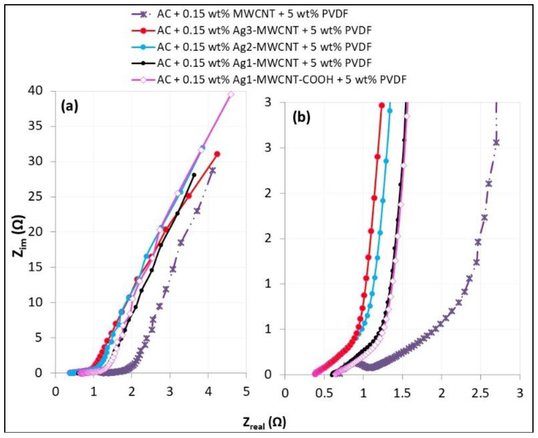
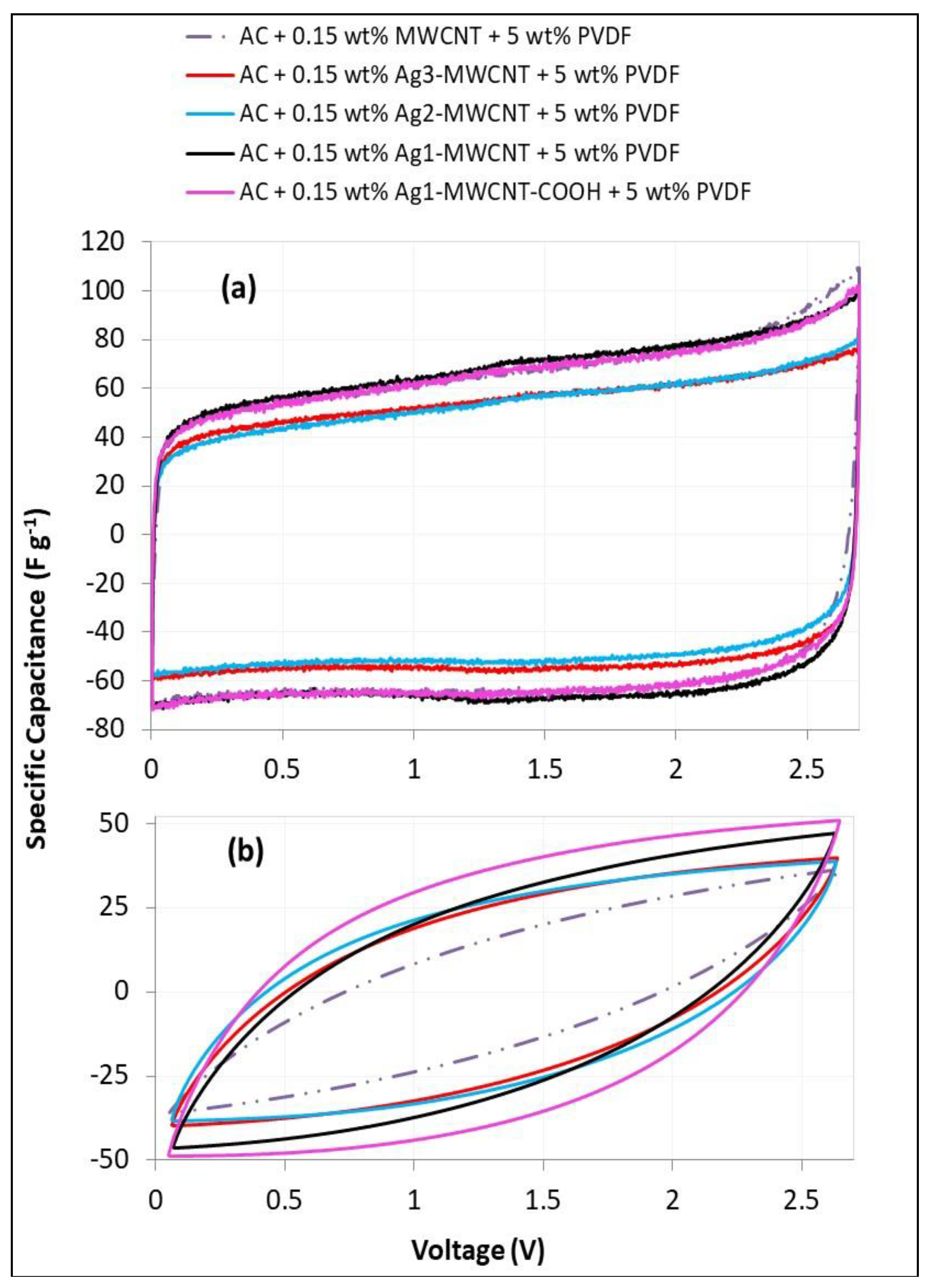
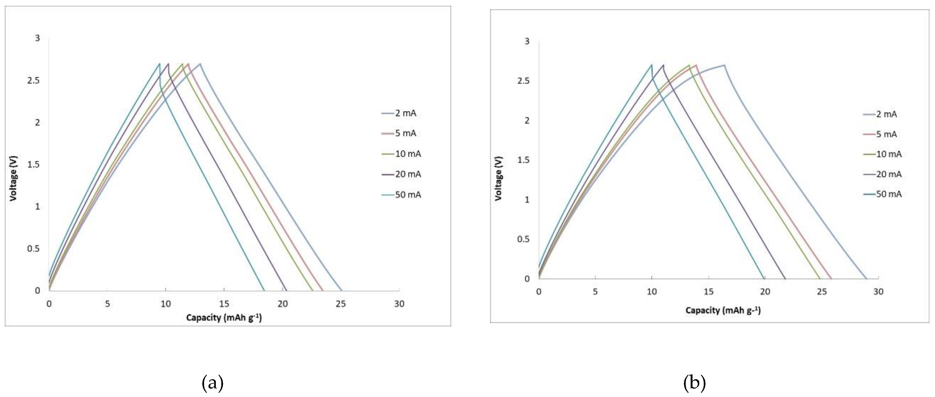
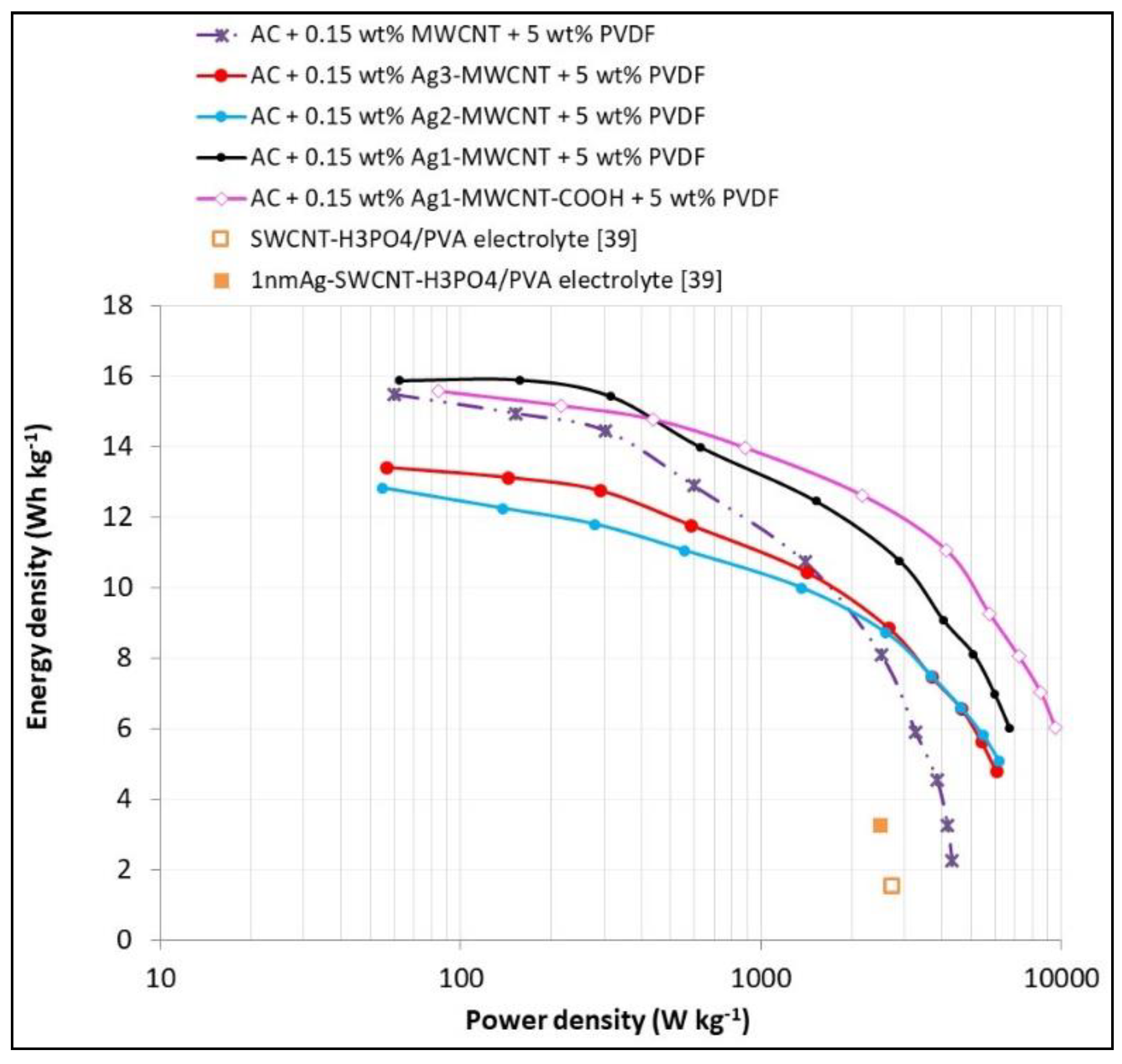
The produced Ag-decorated MWCNT samples, as well as the original MWCNT powders, were characterized via X-ray diffraction using a Siemens D500 X-Ray diffractometer. The produced composite coatings were examined by atomic force microscopy (AFM) in tapping mode using a Bruker AFM microscope and by high resolution scanning microscopy (SEM) using a JEOL JSM-7100F instrument (Tokyo, Japan). The produced coatings as well as the original AC and MWCNT powders were characterized in nitrogen gas adsorption tests at 77 K and in the pressure range of 0.001–800 Torr, using a Beckman Coulter SA 3100 Instrument (Los Angeles, CA, USA). The data were analyzed using the instrument’s commercial software to derive the BET specific surface area and the pore size distribution according to the BJH method [40].
The fabricated EDLC cells were subjected to the following electrochemical tests. Electrochemical impedance spectroscopy (EIS) involved testing at a frequency scan in the range of 0.1 to 106 Hz. The data were plotted in a Nyquist plot of imaginary impedance, Zim, versus real impedance, Zreal, (Zreal is the resistance) from the highest to the lowest frequency point. Cyclic voltammetry (CV) tests involved cycles of charge–discharge at a constant scan rate, r, i.e., voltage increase or decrease rate (in V/s), respectively; electric current, I, measurements were then obtained, from which the specific electrode capacitance, Cel,sp, was calculated from Equation (1), where mel is the mass of one electrode in the EDLC:
C e l , s p = 2 I m e l r .
Galvanostatic charge–discharge (GCD) tests involved charge–discharge at a constant current, while the voltage was measured during the test. The charge/discharge time (h), t, data were translated into the specific charge capacity (mAh/g), Csp, data for the whole EDLC cell according to Equation (2):
c s p = I t 2 m e l .
From the discharge curve of the GCD tests, the energy was calculated as the integral: I∫Vdt and the power was calculated as the integral I∫dV, both over the discharge duration; these values were then divided by the total mass of both electrodes of the cell to determine energy density and power density. Repeating this for all the GCD tests at all tested currents yielded the Ragone plot of energy density versus power density.

3. Results

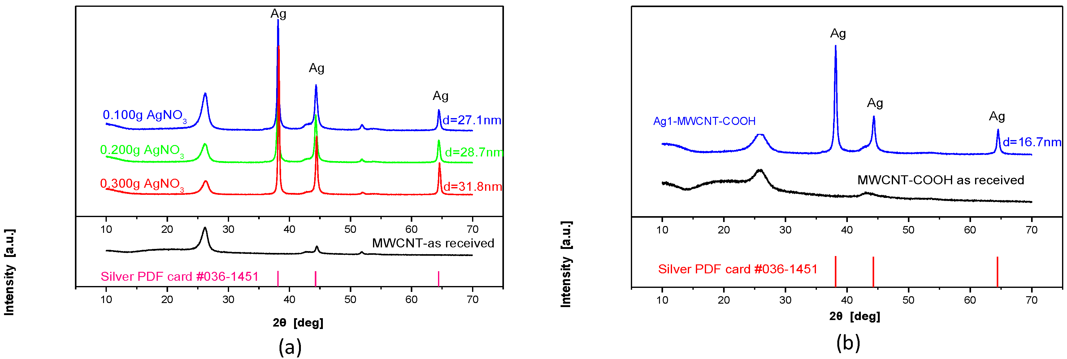
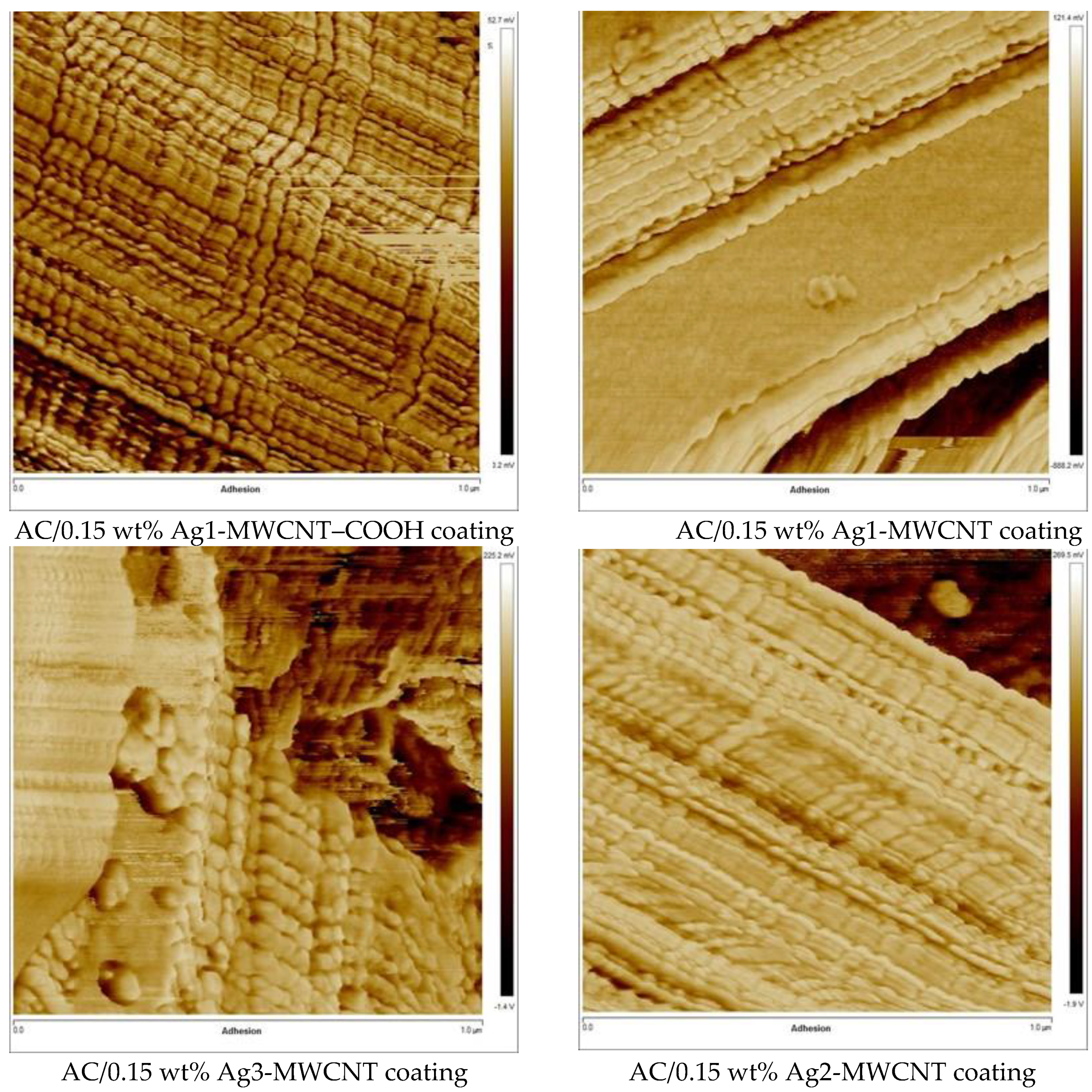
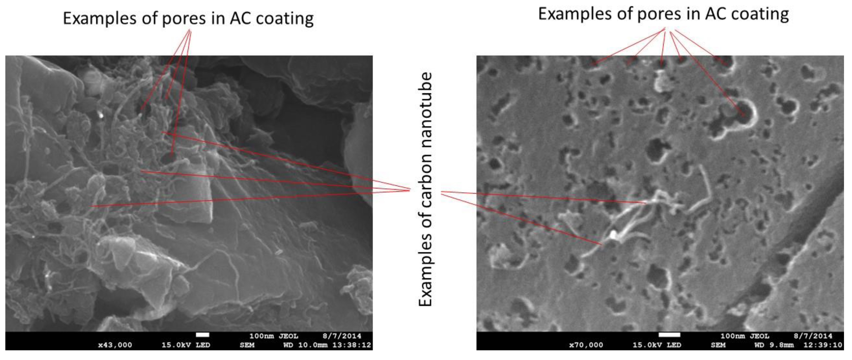
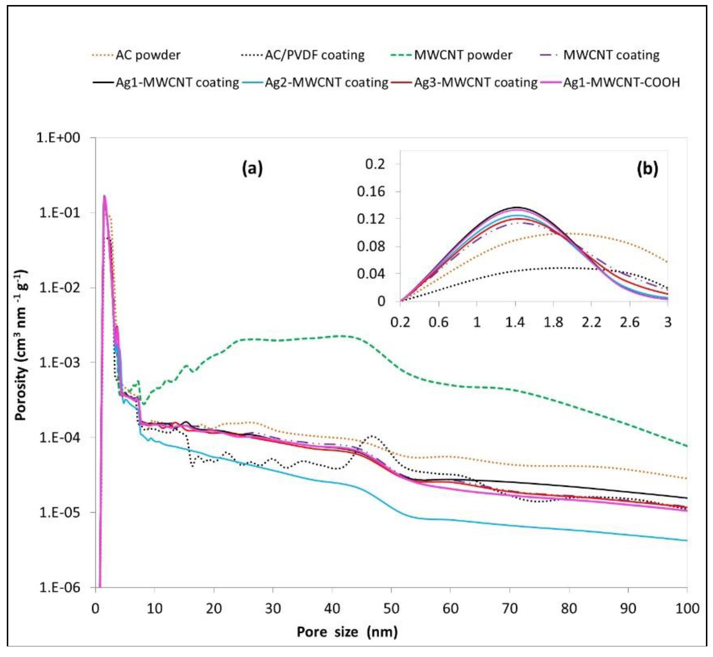
3.1. Characterization of the Composite Electrodes

Figure 1 displays the X-ray diffraction (XRD) patterns of the samples prepared as in Table 1 as well as the undecorated MWCNT and MWCNT–COOH samples. The XRD patterns exhibit three strong Bragg reflections corresponding to the 111, 200 and 220 planes for Ag. From the Ag peaks intensity the Ag content is estimated in Table 2, linearly increasing as the mass of AgNO3 was increased during the preparation. Employing the Debye–Scherrer formula, an average Ag crystallite size was estimated (Table 2) in the range of 27–32 nm in the Ag-MWCNT samples (slightly increasing with the Ag content) but was much smaller, 16.7 nm, in the Ag1-MWCNT–COOH sample (compared to 27.1 nm in the corresponding Ag1-MWCNT sample).
Figure 2 presents AFM images of coatings with the four different types of Ag-decorated MWCNTs. The silver nanoparticles are clearly visible, closely packed. Their size reflects the data in Table 2 and, in particular, the small size of Ag nanoparticles on the MWCNT–COOH material and the larger gaps between the Ag nanoparticles in this material compared to the other three coatings are evident. Figure 3 presents examples of SEM images of composite coatings where good dispersion of the nanotubes can be seen as well as pores of the AC particles at macro- and meso-scale. Micropores (below 2 nm size) cannot be seen at the scale of the SEM images.
Figure 4 displays the pore size distribution of the different types of composite coatings and the initial materials. From the BET values reported in the caption of Figure 4 it can be seen that the coating has less specific surface area than the AC powder due to the PVDF binder blocking some of the pores in the full pore size range (macro-, meso-, micropores). The Ag decoration of MWCNTs increases the MWCNT diameter and reduces the coating BET by about 5%. Decoration with small Ag nanoparticles in the case of Ag1-MWCNT–COOH further reduces the coating BET by 10% overall, due to the close packing of MWCNTs and blocking of AC pores.

3.2. Results of the Electrochemical Testing of Supercapacitor Cells

Figure 5 displays the EIS data in Nyquist plots for the tested EDLCs with different types of composite electrode coatings. A contact resistance of about 0.5 Ω can be observed between the AC + 0.15 wt% MWCNT coating electrode and the current collector (aluminium foil), which is determined from the diameter of the semi-circle in Figure 5b between the first intercept point and the almost second intercept point of the Zreal axis with the Nyquist curve. There is no contact resistance for the other composite electrode coatings with Ag-decorated MWCNTs. In fact, the higher the content of Ag on the nanotubes is, the smaller the cell resistance is, with the Ag3-MWCNT coating exhibiting the lowest resistance.
Figure 6 presents the CV plots at two different scan rates: 0.01 and 1 V·s−1. The highest specific capacitance is observed at the lowest scan rate, as expected, given that at slow charge–discharge rates the ions have the opportunity to access the smallest micropores that offer the greater surface area for the charge to accumulate. It is noticed that the MWCNT decoration with high percent of Ag nanoparticles offers lower capacitance at the low scan rates, which might be attributed to some extent to the reduction of the BET surface area. However, the Ag1-MWCNT and, to some extent, the Ag1-MWCNT–COOH composite electrodes maintain high capacitance despite the greater BET reduction than in Ag2-MWCNT and Ag3-MWCNT. One may speculate that the small degree of pseudocapacitance due to the Ag nanoparticles may have overcome the effect of BET reduction. At the higher scan rate, the Ag1-MWCNT–COOH composite electrode clearly offers the highest specific capacitance.
These findings are replicated also by the galvanostatic charge–discharge data, where Figure 7 clearly shows higher specific capacity during charge for the Ag1-MWCNT–COOH composite electrode due to pseudocapacitance. The galvanostatic discharge data at different currents have been used to derive the Ragone plot in Figure 8 for EDLCs with different types of composite electrode coatings. While the Ag1-MWCNT–COOH composite electrodes-based EDLC has similar energy density as the undecorated MWCNT composite electrodes-based EDLC at low power densities, the former retains a good energy density to higher power densities, 6 Wh·kg−1 at 10 kW·kg−1, against 5.9 Wh·kg−1 at 3.3 kW·kg−1 for the latter.

4. Discussion

Taking into account the quantities of reagents in Table 1 and the composition of the Ag-decorated MWCNTs in Table 2, it seems that the Ag decoration process had a yield of 72.3–73.7% for the Ag-decorated unfunctionalized MWCNTs and 85.6% for the Ag1-MWCNT–COOH, with respect to Ag. Of course, any unused Ag material may be recycled in a future process scale-up. The same group has produced Ag-rGO (Ag-decorated reduced graphene oxide) [41] with similar Ag crystallite sizes, 21–33 nm, as the Ag-MWCNT materials in Table 2 in this study, but there was only 0.1–1 wt% Ag in the Ag-rGO material, much lower than 8.5–22 wt% in the Ag-MWCNT materials of this study. It is clear in Table 2 that the Ag1-MWCNT–COOH material contains Ag nanoparticles of much smaller size, 16.7 nm, than the Ag-MWCNT materials (27.1–31.8 nm). It is believed that the –COOH functional groups on the MWCNTs act as anchoring sites for the Ag+ ions before their reduction, thus facilitating the better dispersion of nanocrystals and the avoidance of agglomeration.
Compared to other studies in the literature, Shi et al. [42] seem to have achieved similar Ag nanoparticle size in the decoration of carbon nanotubes of about 50 nm diameter whereas Wee et al. [39] managed to achieve a range of smaller Ag nanoparticles, 1–13 nm, in Ag-decorated SWCNTs. Wee et al. [39] also fabricated supercapacitor cells with electrolyte H3PO4/PVA (polyvinyl alcohol) and tested these cells: their single point data for their various cells placed on a Ragone plot, shown also in Figure 8 in comparison to the results of this study, demonstrate a low performance SWCNT-based cell at 1.5 Wh·kg−1 and 2.75 kW·kg−1; their best cell with 1 nm Ag-decorated SWCNTs had double the energy density of the SWCNT-based cell, demonstrating the effect of the pseudocapacitance of Ag nanoparticles, but slightly lower power density than the SWCNT-based cell. The large pseudocapacitance effect in the energy density value in [39] might be attributed to the fact that the whole SWCNT electrode material was decorated with Ag nanoparticles. In comparison, the composite coating in the present study contains only 0.15 wt% MWCNTs which are decorated with Ag nanoparticles, the rest of the coating consists of high specific capacitance AC material which results in much higher energy density for the AC + 0.15 wt% MWCNT coating-based cell in Figure 8 than the cells in [39]; the small rise of 6% in the energy density due to the pseudocapacitance of Ag1-MWCNTs for the AC + 0.15 wt% Ag1-MWCNT coating-based cell in Figure 8 is then understandable, given the small amount of MWCNT material in the electrode coating overall.
The Nyquist plots from the EIS data in Figure 5 show that composite electrodes containing the highly conductive MWCNT additive have still a contact resistance of 1 Ω·cm2 (0.5 Ω for an EDLC of 2 cm2 in Figure 2). The major benefit of Ag-decorated MWCNTs in this study is that the contact resistance is eliminated, while the conductivity in the EDLC increases as the Ag content is increased.
The slow scan rate CV plot (Figure 6a) shows that the Ag2-MWCNT and Ag3-MWCNT composite electrodes reduce the specific capacitance, which might be attributed to some extent to the reduction of the BET surface area. However, the Ag1-MWCNT and Ag1-MWCNT–COOH composite electrodes maintain higher capacitance, despite the greater BET reduction, than in Ag2-MWCNT and Ag3-MWCNT composite coatings. The Ag1-MWCNT, and to a smaller degree, the Ag1-MWCNT–COOH composite coating-based EDLC display small CV bumps in the range of 1.3–1.9 V during charge and 1.05–1.7 V during discharge indicating surface redox [37] for both EDLCs and some intercalation with partial redox [37] for the Ag1-MWCNT composite coating-based EDLC. Hence, the increased specific electrode capacitance at these points may be attributed to the pseudocapacitance due to the Ag nanoparticles that has also overcome the effect of BET reduction. The pseudocapacitance effect is more prominent for the Ag1-MWCNT composite electrode, which exhibits a mid-voltage (at 1.35 V) specific electrode capacitance of 71.4 F·g−1 during charge and 69.1 F·g−1 in discharge, against 65.6 F·g−1 and 63.3 F·g−1, respectively, for the undecorated MWCNT composite electrode. In similar studies but with a PVA/H3PO4 electrolyte, Wee et al. [39] observed that 1 nm Ag particles in Ag-SWCNT electrodes created large reversible Faradaic redox effects in the range of 0.1–0.3 V during charge and close to 0 V in discharge. Apart from the small Ag particle size in [39], it must also be considered that the small H+ ions in the aqueous H3PO4 electrolyte in [39] diffuse much faster than the large TEA+ ions of the organic electrolyte in this study, hence the pseudocapacitance effect may be larger in [39]. The main effect is of course that the electrode in [39] is fully SWCNT-based, so all coating material is decorated with Ag nanoparticles, where in the present study MWCNTs comprise only 0.15 wt% of the whole composite electrode coating.
Clearly, the Ag1-MWCNT–COOH composite electrode maintains higher specific capacitance at the high scan rate CV (Figure 6b) which is attributed to the fact that with the elimination of the contact resistance between the electrode coating and the current collector foil (as in any case for all Ag-decorated MWCNT composite coatings), the electrolyte ions can freely travel and reach more smaller pores in the Ag1-MWCNT–COOH electrode due to the large number of mesopores forming because of the large gaps between the small Ag nanoparticles of the Ag1-MWCNT–COOH electrode (Figure 2). As a result, the whole Ragone plot of the Ag1-MWCNT–COOH composite electrode-based EDLC is shifted to higher power densities in Figure 8, which represents a 190% increase of the power density for this EDLC compared to the undecorated MWCNT composite electrode-based EDLC. The Ag1-MWCNT composite electrode-based EDLC, with similar Ag content but larger Ag nanoparticles than Ag1-MWCNT–COOH, contributes a 105% increase in the power density compared to the undecorated MWCNT composite electrode-based EDLC and also a 6% increase in energy density at slow rates of discharge due to pseudocapacitance contributions.
In terms of cost, the composite coatings contain only 0.15 wt% MWCNT and only 0.015 wt% Ag materials. Where needed, the supercapacitor materials can be recycled according to established procedures [43] of disassembling the cell, washing the components, dissolving the polymer binder [44,45] and separating the solid AC, MWCNT and Ag particles via dielectrophoresis [46].

5. Conclusions

Novel composite electrodes were manufactured and investigated in this study, containing high surface area activated carbon and Ag-decorated MWCNTs. The decoration procedure involved MWCNT powder and AgNO3 as the initial materials and reductive agent NaBH4 for the reduction of Ag+ to zero-valent Ag nanoparticles. It was found that carboxylic group functionalized MWCNTs (MWCNT–COOH) were decorated with smaller Ag nanoparticles of 16.7 nm, also leaving interparticle gaps. The decoration of unfunctionalized MWCNTs yielded densely packed Ag nanoparticles of 27–32 nm, with the particle size increasing linearly against Ag content. The novel composite electrodes were used in the fabrication of EDLCs with organic electrolyte 1.5 M TEABF4/AN. The Ag-decorated MWCNTs eliminated the contact resistance between electrode and current collector that existed when undecorated MWCNTs were used in the composite electrodes. Compared to the undecorated MWCNT-containing composite electrodes, Ag decoration of the MWCNTs in the composite electrodes tripled and doubled the power density for the Ag1-MWCNT–COOH and the Ag1-MWCNT composite electrodes, respectively. Furthermore, the contributions of pseudocapacitance raised the energy density by 6% (to 15.9 Wh·kg−1) in the EDLCs with the Ag1-MWCNT composite electrodes. The benefits of optimized composite electrodes are apparent when the results are compared to EDLCs with the corresponding AC-only coating electrode in the study by Markoulidis et al. [25] with their test data interpolated to the same potential range of 0–2.7 V as in this study: whereas the AC coating-based EDLCs presented an electrode capacitance of 50 F·g−1 and energy density of 12.2 Wh·kg−1, the corresponding data in the current study are 69.1 F·g−1 and 15.9 Wh·kg−1 for the Ag1-MWCNT composite electrode-based EDLCs and 63.3 F·g−1 and 14.9 Wh·kg−1 for the Ag1-MWCNT–COOH composite electrode-based EDLCs. Furthermore, it is remarkable that the superior composite electrodes of this study contain only 0.15 wt% MWCNT and 0.015 wt% Ag.

Author Contributions

Conceptualization, C.T. (Ag decoration of MWCNTs), C.L. (supercapacitors); methodology, N.T. and C.T. (Ag decoration of MWCNTs, characterization), C.L. (coating characterization, supercapacitors fabrication and testing); experimental work, data analysis, F.M., N.T. and R.G.; writing—original draft preparation, C.L.; review and editing, C.T., F.M. and N.T. supervision, C.L., C.T.; funding acquisition, C.L., C.T.

Funding

This research was funded by the EC-funded FP7 project AUTOSUPERCAP, project no 266097.

Conflicts of Interest

The authors declare no conflict of interest.

References

  1. Fields, R.; Lei, C.; Markoulidis, F.; Lekakou, C. The composite supercapacitor. Energy Technol. 2016, 4, 517–525. [Google Scholar] [CrossRef]
  2. Zuo, W.; Li, R.; Zhou, C.; Li, Y.; Xia, J.; Liu, J. Battery-supercapacitor hybrid devices: Recent progress and future prospects. Adv. Sci. 2017, 4, 1600539. [Google Scholar] [CrossRef] [PubMed]
  3. Banerjee, A.; Srinivasan, R.; Shukla, A.K. Design of substrate-integrated lead-carbon hybrid ultracapacitor and experimental validation. ECS Electrochem. Lett. 2014, 3, A1–A3. [Google Scholar] [CrossRef]
  4. Shirshova, N.; Qian, H.; Houllé, M.; Steinke, J.H.; Kucernak, A.R.; Fontana, Q.P.; Greenhalgh, E.S.; Bismarck, A.; Shaffer, M.S. Multifunctional structural energy storage composite supercapacitors. Faraday Discuss. 2014, 172, 81–103. [Google Scholar] [CrossRef] [PubMed] [Green Version]
  5. Li, Q.; Zhu, Y.Q.; Eichhorn, S.J. Structural supercapacitors using a solid resin electrolyte with carbonized electrospun cellulose/carbon nanotube electrodes. J. Mater. Sci. 2018, 53, 14598–14607. [Google Scholar] [CrossRef] [Green Version]
  6. Reece, R.; Lekakou, C.; Smith, P.A. A structural supercapacitor based on activated carbon fabric and a solid electrolyte. Mater. Sci. Technol. 2018, 35, 368–375. [Google Scholar] [CrossRef]
  7. Moudam, O.; Andrews, T.; Lekakou, C.; Watts, J.F.; Reed, G. Carbon nanotube-epoxy nanocomposites: Correlation and integration of dynamic impedance, dielectric, and mechanical analyses. J. Nanomater. 2013, 2013, 801850. [Google Scholar] [CrossRef]
  8. Rutt, M.; Lekakou, C.; Smith, P.A.; Sordon, A.; Santoni, C.; Meeks, G.; Hamerton, I. Methods for process-related resin selection and optimisation in high-pressure resin transfer moulding. Mater. Sci. Technol. 2018, 35, 327–335. [Google Scholar] [CrossRef]
  9. Bodaghi, M.; Simacek, P.; Advani, S.G.; Correia, N.C. A model for fibre washout during high injection pressure resin transfer moulding. J. Reinf. Plast. Compos. 2018, 37, 865–876. [Google Scholar] [CrossRef]
  10. Schmidt, T.M.; Goss, T.M.; Amico, S.C.; Lekakou, C. Permeability of hybrid reinforcements and mechanical properties of their composites molded by resin transfer molding. J Reinf. Plast. Compos. 2009, 28, 2839–2850. [Google Scholar] [CrossRef]
  11. Wang, C.; Ye, J.; Yue, G.; Bai, G.; Liu, L.; Zhang, B. Mechanical properties of the cured laminates on the hot-press tackified preforms in vacuum assisted resin transfer molding. J. Wuhan Univ. Technol.-Mater. Sci. Ed. 2018, 33, 242–248. [Google Scholar] [CrossRef]
  12. Eckler, J.H.; Wilkinson, T.C. Processing and designing parts using structural reaction injection molding. J. Mater. Shap. Technol. 1987, 5, 17–21. [Google Scholar] [CrossRef]
  13. Lekakou, C.N.; Richardson, S.M. Simulation of reacting flow during filling in reaction injection moulding (RIM). Polym. Eng. Sci. 1986, 26, 1264–1275. [Google Scholar] [CrossRef]
  14. Ciucci, F.; Lai, W. Derivation of micro/macro lithium battery models from homogenization. Transp. Porous Media 2011, 88, 249–270. [Google Scholar] [CrossRef]
  15. Amico, S.; Lekakou, C. Flow through a two-scale porosity, oriented fibre porous medium. Transp. Porous Media 2004, 54, 35–53. [Google Scholar] [CrossRef]
  16. Reece, R.; Lekakou, C.; Smith, P.A.; Grilli, R.; Trapalis, C. Sulphur-linked graphitic and graphene oxide platelet-based electrodes for electrochemical double layer capacitors. J. Alloys Compd. 2019, 792, 582–593. [Google Scholar] [CrossRef]
  17. Hwang, J.Y.; Li, M.; El-Kady, M.F.; Kaner, R.B. Next-generation activated carbon supercapacitors: A simple step in electrode processing leads to remarkable gains in energy density. Adv. Funct. Mat. 2017, 27, 1605745. [Google Scholar] [CrossRef]
  18. Wang, Y.; Shi, Z.; Huang, Y.; Ma, Y.; Wang, C.; Chen, M.; Chen, Y. Supercapacitor devices based on graphene materials. J. Phys. Chem. C 2009, 113, 13103–13107. [Google Scholar] [CrossRef]
  19. Zhu, Y.; Murali, S.; Stoller, M.D.; Ganesh, K.J.; Cai, W.; Ferreira, P.J.; Pirkle, A.; Wallace, R.M.; Cychosz, K.A.; Thommes, M.; et al. Carbon-based supercapacitors produced by activation of graphene. Science 2011, 332, 1537–1541. [Google Scholar] [CrossRef] [PubMed]
  20. Vermisoglou, E.C.; Giannakopoulou, T.; Romanos, G.; Boukos, N.; Giannouri, M.; Lei, C.; Lekakou, C.; Trapalis, C. Non-Activated High Surface Area Expanded Graphite Oxide for Supercapacitors. Appl. Surf. Sci. Part A 2015, 358, 110–121. [Google Scholar] [CrossRef]
  21. Vermisoglou, E.C.; Giannakopoulou, T.; Romanos, G.; Giannouri, M.; Boukos, N.; Lei, C.; Lekakou, C.; Trapalis, C. Effect of hydrothermal reaction time and alkaline conditions on the electrochemical properties of reduced graphene oxide. Appl. Surf. Sci. Part A 2015, 358, 100–109. [Google Scholar] [CrossRef]
  22. Vermisoglou, E.C.; Giannakopoulou, T.; Romanos, G.; Boukos, N.; Psycharis, V.; Lei, C.; Lekakou, C.; Petridis, D.; Trapalis, C. Graphene-based materials via benzidine-assisted exfoliation and reduction of graphite oxide and their electrochemical properties. Appl. Surf. Sci. 2017, 392, 244–255. [Google Scholar] [CrossRef]
  23. Chen, X.; Paul, R.; Dai, L. Carbon-based supercapacitors for efficient energy storage. Natl. Sci. Rev. 2017, 4, 453–489. [Google Scholar] [CrossRef]
  24. Bu, P.; Liu, S.; Lu, Y.; Zhuang, S.; Wang, H.; Tu, F. Effects of carbon black on the electrochemical performance of lithium-organic coordination compound batteries. Int. J. Electrochem. Sci. 2012, 7, 4617–4624. [Google Scholar]
  25. Markoulidis, F.; Lei, C.; Lekakou, C.; Duff, D.; Khalil, S.; Martorana, B.; Cannavaro, I. A method to increase the energy density of supercapacitor cells by the addition of multiwall carbon nanotubes into activated carbon electrodes. Carbon 2014, 68, 58–66. [Google Scholar] [CrossRef]
  26. Markoulidis, F.; Lei, C.; Lekakou, C. Fabrication of high-performance supercapacitors based on transversely oriented carbon nanotubes. Appl. Phys. A Mater. Sci. Process. 2013, 111, 227–236. [Google Scholar] [CrossRef]
  27. Lekakou, C.; Moudam, O.; Markoulidis, F.; Andrews, T.; Watts, J.F.; Reed, G. Carbon-based fibrous EDLC capacitors and supercapacitors. J. Nanotechnol. 2011, 2011, 409382. [Google Scholar] [CrossRef]
  28. Lei, C.; Lekakou, C. Activated carbon–carbon nanotube nanocomposite coatings for supercapacitor application. Surf. Coat. Technol. 2013, 232, 326–330. [Google Scholar] [CrossRef]
  29. Lei, C.; Markoulidis, F.; Wilson, P.; Lekakou, C. Phenolic carbon cloth-based electric double-layer capacitors with conductive interlayers and graphene coating. J. Appl. Electrochem. 2016, 46, 251–258. [Google Scholar] [CrossRef]
  30. Markoulidis, F.; Lei, C.; Lekakou, C. Investigations of activated carbon fabric-based supercapacitors with different interlayers via experiments and modelling of electrochemical processes of different timescales. Electrochim. Acta 2017, 249, 122–134. [Google Scholar] [CrossRef]
  31. Dinh, T.M.; Pech, D.; Brunet, M.; Achour, A. High resolution electrochemical micro-capacitors based on oxidized multi-walled carbon nanotubes. J. Phys. Conf. Ser. 2013, 476, 012106. [Google Scholar] [CrossRef] [Green Version]
  32. Sianipar, M.; Kim, S.H.; Iskandar, F. Functionalized carbon nanotube (CNT) membrane: Progress and challenges. RSC Adv. 2017, 7, 51175–51198. [Google Scholar] [CrossRef]
  33. Shirvanimoghaddam, K.; Abolhasani, M.M.; Li, Q.; Khayyam, H.; Naebe, M. Cheetah skin structure: A new approach for carbon-nano-patterning of carbon nanotubes. Compos. Part A 2017, 95, 304–314. [Google Scholar] [CrossRef]
  34. Wilson, P.; Lekakou, C.; Watts, J.F. In-plane conduction characterisation and charge transport model of DMSO co-doped, inkjet printed Poly(3,4-ethylenedioxythiophene): Polystyrene sulfonate (PEDOT:PSS). Org. Electron. 2013, 14, 3277–3285. [Google Scholar] [CrossRef]
  35. Wilson, P.; Lei, C.; Lekakou, C.; Watts, J.F. Transverse charge transport in inkjet printed poly(3,4-ethylenedioxythiophene) polystyrene sulfonate (PEDOT:PSS). Org. Electron. 2014, 15, 2043–2051. [Google Scholar] [CrossRef] [Green Version]
  36. Lei, C.; Wilson, P.; Lekakou, C. Effect of poly(3,4-ethylenedioxythiophene) (PEDOT) in carbon-based composite electrodes for electrochemical supercapacitors. J. Power Sources 2011, 196, 7823–7827. [Google Scholar] [CrossRef] [Green Version]
  37. Gogotsi, Y.; Penner, R.M. Energy Storage in Nanomaterials—Capacitive, Pseudocapacitive, or Battery-like? ACS Nano 2018, 12, 2081–2083. [Google Scholar] [CrossRef] [PubMed]
  38. Vermisoglou, E.C.; Devlin, E.; Giannakopoulou, T.; Romanos, G.; Boukos, N.; Psycharis, V.; Lei, C.; Lekakou, C.; Petridis, D.; Trapalis, C. Reduced graphene oxide/iron carbide nanocomposites for magnetic and supercapacitor applications. J. Alloys Compd. 2014, 590, 102–109. [Google Scholar] [CrossRef]
  39. Wee, G.; Mak, W.F.; Phonthammachai, N.; Kiebele, A.; Reddy, M.V.; Chowdari, B.V.R.; Gruner, G.; Srinivasan, M.; Mhaisalkara, S.G. Particle size effect of silver nanoparticles decorated single walled carbon nanotube electrode for supercapacitors. J. Electrochem. Soc. 2010, 157, A179–A184. [Google Scholar] [CrossRef]
  40. Coasne, B.; Gubbins, K.E.; Pellenq, R.J.-M. A Grand Canonical Monte Carlo study of adsorption and capillary phenomena in nanopores of various morphologies and topologies: Testing the BET and BJH characterization methods. Part. Part. Syst. Charact. 2004, 21, 149–160. [Google Scholar] [CrossRef]
  41. Papailias, I.; Giannouri, M.; Trapalis, A.; Todorova, N.; Giannakopoulou, T.; Boukos, N.; Lekakou, C. Decoration of crumpled rGO sheets with Ag nanoparticles by spray pyrolysis. Appl. Surf. Sci. 2015, 358, 84–90. [Google Scholar] [CrossRef]
  42. Shi, Y.; Liu, Z.; Zhao, B.; Sun, Y.; Xu, F.; Zhang, Y.; Wen, Z.; Yang, H.; Li, Z. Carbon nanotube decorated with silver nanoparticles via noncovalent interaction for a novel nonenzymatic sensor towards hydrogen peroxide reduction. J. Electroanal. Chem. 2011, 656, 29–33. [Google Scholar] [CrossRef]
  43. Vermisoglou, E.C.; Giannouri, M.; Todorova, N.; Giannakopoulou, T.; Lekakou, C.; Trapalis, C. Recycling of typical supercapacitor materials. Waste Manag. Res. 2016, 34, 337–344. [Google Scholar] [CrossRef] [PubMed] [Green Version]
  44. Kampouris, E.M.; Papaspyrides, C.D.; Lekakou, C.N. A model recovery process for scrap polystyrene foam by means of solvent systems. Conserv. Recycl. 1987, 10, 315–319. [Google Scholar] [CrossRef]
  45. Kampouris, E.M.; Papaspyrides, C.D.; Lekakou, C.N. A model process for the solvent recycling of polystyrene. Polym. Eng. Sci. 1988, 28, 534–537. [Google Scholar] [CrossRef]
  46. Murugesh, A.K.; Uthayanan, A.; Lekakou, C. Electrophoresis and orientation of multiple wall carbon nanotubes in polymer solution. Appl. Phys. A Mater. Sci. Process. 2010, 100, 135–144. [Google Scholar] [CrossRef]
Figure 1. X-ray diffraction patterns of (a) undecorated MWCNT and Ag1-MWCNT, Ag2-MWCNT and Ag3-MWCNT; (b) undecorated MWCNT–COOH and Ag1-MWCNT–COOH.
Jcs 03 00097 g001
Figure 2. AFM adhesion force maps for composite coatings with different types of Ag-decorated MWCNTs. In all cases, image width scale = 1 um.
Jcs 03 00097 g002
Figure 3. HR-SEM images of a composite coating from this study at different magnifications; scale bar = 100 nm.
Jcs 03 00097 g003
Figure 4. Pore size distribution of initial materials and composite coatings. The derived BET specific surface area values are as follows: AC powder: 926 m2·g−1; MWCNT powder: 145 m2·g−1; AC + 0.15 wt% MWCNT + 5 wt% PVDF coating: 707 m2·g−1; AC + 0.15 wt% Ag3-MWCNT + 5 wt% PVDF: 672 m2·g−1; 0.15 wt% Ag2-MWCNT + 5 wt% PVDF: 676 m2·g−1; 0.15 wt% Ag1-MWCNT + 5 wt% PVDF: 646 m2·g−1; 0.15 wt% Ag1-MWCNT–COOH + 5 wt% PVDF: 638 m2·g−1.
Jcs 03 00097 g004
Figure 5. Electrochemical impedance spectroscopy results for the tested electrochemical double layer capacitors (EDLCs) with different types of composite electrode coatings: (a) the full Nyquist plot; (b) magnified scales near the axes origin.
Jcs 03 00097 g005
Figure 6. Cyclic voltammetry results for EDLCs with different types of composite electrode coatings: (a) at 0.01 V·s−1; (b) at 1 V·s−1. The vertical axis is specific electrode capacitance, representing the capacitance (F) of a half cell per mass (g) of one composite electrode. Average Cel,sp values from integration over a whole CV cycle at 0.01 V·s−1 (Figure 6a) ± standard error from two tested sample cells in each case: AC + 0.15 wt% MWCNT + 5 wt% PVDF coating: 63.92 ± 0.03 F·g−1; AC + 0.15 wt% Ag1-MWCNT + 5 wt% PVDF: 65.91 ± 0.03 F·g−1; 0.15 wt% Ag2-MWCNT + 5 wt% PVDF: 51.69 ± 0.03 F·g−1; 0.15 wt% Ag3-MWCNT + 5 wt% PVDF: 53.82 ± 0.03 F·g−1; 0.15 wt% Ag1-MWCNT–COOH + 5 wt% PVDF: 63.88 ± 0.03 F·g−1.
Jcs 03 00097 g006
Figure 7. Galvanostatic charge–discharge results for EDLCs with composite electrodes containing (a) 0.15 wt% MWCNT; (b) 0.15 wt% Ag1-MWCNT–COOH. The capacity values represent charge (mAh) per total mass (g) of the two composite electrodes in the EDLC cell.
Jcs 03 00097 g007
Figure 8. Ragone plot for EDLCs with different types of composite electrode coatings, created from the results of galvanostatic discharge at different currents in the range of 0–2.7 V. The energy density and power density values are per total mass (kg) of the two composite electrodes in the EDLC cell. Also shown is a comparison with experimental data from a study by Wee et al. [39].
Jcs 03 00097 g008
Table 1. Quantities of reagents and nomination of the Ag-decorated multiwall carbon nanotubes (MWCNT) samples.
Sample NameQuantity AgNO3
(g)
Quantity MWCNT
(g)
Quantity NaBH4
(g)
Ag1-MWCNT0.1000.50.200
Ag2-MWCNT0.2000.50.400
Ag3-MWCNT0.3000.50.600
Ag1-MWCNT–COOH0.1000.50.200
Table 2. Weight content of the Ag and average size of the Ag particles calculated from XRD measurements.
Sample NameAg Content (wt%)Ag Particle Size (nm)
Ag1-MWCNT8.527.1
Ag2-MWCNT15.528.7
Ag3-MWCNT21.931.8
Ag1-MWCNT–COOH9.816.7

