Strain State Detection in Composite Structures: Review and New Challenges


Department of Industrial Engineering, Aerospace Section, University of Naples “Federico II”, Via Claudio 21, 80125 Naples, Italy
*
Author to whom correspondence should be addressed.
J. Compos. Sci. 2020, 4(2), 60; https://0-doi-org.brum.beds.ac.uk/10.3390/jcs4020060
Submission received: 26 April 2020
/
Revised: 14 May 2020
/
Accepted: 17 May 2020
/
Published: 25 May 2020
(This article belongs to the Special Issue Characterization and Modelling of Composites)
Abstract
:Developing an advanced monitoring system for strain measurements on structural components represents a significant task, both in relation to testing of in-service parameters and early identification of structural problems. This paper aims to provide a state-of-the-art review on strain detection techniques in composite structures. The review represented a good opportunity for direct comparison of different novel strain measurement techniques. Fibers Bragg grating (FBG) was discussed as well as non-contact techniques together with semiconductor strain gauges (SGs), specifically infrared (IR) thermography and the digital image correlation (DIC) applied in order to detect strain and failure growth during the tests. The challenges of the research community are finally discussed by opening the current scenario to new objectives and industrial applications.
1. Preface and Motivation
For the development of lightweight structures, in recent decades, the use of advanced composite materials and modern manufacturing methods has intensified the need to provide effective means of performing experimental investigations to support analytical and numerical analyses. The complexity and high associated costs of full-scale experiments indicate enhancing the reliability of the experimental research to improve precise and effective techniques capable of reducing full-scale testing to subcomponent testing. In the aerospace industry, for instance, several application areas have garnered significant interest. In effect, structural monitoring can improve the characterization and prediction of effects associated with failure that affect the structural safety. In addition, non-destructive techniques can offer fault tolerance to component/subsystem/system-level, thus offering the possibility to reduce costs associated with ordinary/extraordinary maintenance [1]. Chia et al. illustrated an ambitious plan towards developing smart hangar technology, where noncontact measurements would be used to inspect aircraft structures [2]. Rapid inspection also regarded space structures for pre-launch verification using health monitoring technologies [3,4]. Advanced composite materials have encouraged considerable interest in the research community owing primarily to their increased application in both military and general aviation vehicles. Next-generation marine vessels are also adopting orthotropic materials and, for similar reasons, the need for capable monitoring systems is crucial [5]. In this large framework, many different sensing methodologies have thus been deployed for these structural monitoring applications. Many of these methods are based upon strain measurements, which can be detected by conventional gauges or other techniques [6]. Since 1940, the resistance strain gauges (SGs) exemplified the most powerful tool concerning the experimental stress evaluation, even today representing a common choice for monitoring material deformations and damage on in-service composite vehicles. The physical environment of the strain gauge is, in any case, a crucial parameter that has to be considered in gauge selection and protective coating. Owing to their relatively high surface area and the need for protective coatings, electrical resistance strain gauges have found a lot of difficulties in acceptance of their filling into laminated composite materials. A main drawback to such an approach is given by their surface limitation, so a large quantity of them would be necessary to monitor an entire vehicle, yielding a complex network with a lot of wires and cables. For this reason, the strain gauges’ location is often optimized for the most critical areas. Optical fibers have been introduced recently just to overcome the weaknesses given by conventional SGs. In many approaches, fiber optic sensors are used to achieve static or quasi-dynamic strain, providing better resolution of up to two to three orders of magnitude compared with conventional SGs [7,8,9]. Structural monitoring requirements have increased rapidly in the last few decades, and these requirements have prompted many new developments in various sensing technologies. The present article deals with a review of the strain characterization techniques; the technological approach and introduction to experimental techniques are topics illustrated within the following chapters. In this perspective, Fibers Bragg grating (FBG)-based sensors represent of course the most advantageous application to monitor in situ strains over the life of a component, providing more reliable decisions regarding maintenance and replacement of the system. Additionally, semiconductor-based SGs represent another contact transducers category for embedded structural monitoring applications, revealing a high fatigue life, which makes them very attractive for long-term installations. Infrared (IR) thermography and digital image correlation (DIC) represent attractive non-contact techniques offering an interesting full-field investigation of the material response. Their combination could allow a coupled analysis of different specimen aspects from the early stages of testing. A further, very appealing possible integration of the hybrid monitoring system is that which provides the use of non-destructive and non-contact controls such as online monitoring with infrared thermography or DIC in order to highlight possible hot-spots during the tests. The inspection is accomplished in a remote way, avoiding any direct contact, thus preserving the controlled surface from any contamination. Moreover, it can be performed far away from any dangerous environment, safeguarding the safety of the operator. All these techniques are analyzed here and numerous examples are provided for different damage scenarios and aerospace components in order to identify the strength and limitations of each approach. The development of an efficient monitoring system inevitably has repercussions on the life-cycle of the product. Several scientific studies [10] have shown how the proper implementation of structural monitoring may have a positive effect on a structure’s life-cycle cost, thus achieving a positive cost/benefit ratio. Commercial insights and industry perceptions pointed out many scenarios where immediate, near-term, and long-term cost savings outweigh the cost of the measurement system, confirming the benefits of its implementation.
2. Contact-Based Techniques
2.1. FBG Sensing Network
2.1.1. Theory Background
One of the alternatives to strain gauge-based sensors for structural monitoring is given by FBG optical sensors. The theory of fiber Bragg gratings may be developed by considering the propagation of modes in an optical fiber. Although guided wave optics is well established, the relationship between the mode and the refractive index perturbation in a Bragg grating plays an important role in the overall efficiency and type of scattering allowed by the symmetry of the problem [11]. Being de facto small and flexible, FBG sensors can be embedded discretely into composites at locations of interest, thereby allowing for the detection of local strain distribution and progression without compromising the structural integrity of the host material. Often, it is mandatory for getting the strain state in many stations of the structure; the need for a dense network of sensors, that is, strain gauges, could lead to a considerable size increase of the test set-up, comprising a large amount of electric wirings and so on. From this perspective, optical FBG sensors are lightweight and versatile, they can be non-intrusively inserted into adhesive materials as well as multiplexed into an array of single FBG sensors. Taking into account the advantages of electromagnetic noise tolerance, high sensitivity, and multiplexing capability, the fibre optic sensing technique has been recognised as a reliable means of measuring structural strain response (static and transient), and FBGs have been successfully developed and employed in structural health monitoring (SHM) for strain, temperature, refractive index, or loads measurements. An FBG is a delimited and systemic discontinuity, imprinted on an optical fibre wire, which reflects different wavelengths. Narrowband reflections can be obtained by deploying discontinuities to allow this system to filter those frequencies [12,13,14,15,16,17]. FBGs are formed by exposing an optical fiber to an ultraviolet interference pattern, producing a periodic change in the refraction core index. These periodic changes cause a reflection when the light in the waveguide is of a particular wavelength (owing to the constructive interference of grating plane reflections), while other wavelengths are transmitted in the fiber, as shown in Figure 1 [18].
FBG operation is based on the Fresnel reflection: a broadband light band is diffused into the optical fiber. Once the signal goes through grating, a specific wavelength (i.e., a narrow frequency band, centred at the nominal frequency) is reflected and detected by a spectrometer as well. When fiber is stretched, the gratings time is contracted or expanded and the wavelengths reflected are modulated in turn. The most common way to print gratings inside a glass core fibre is to perform a periodic modulation of the effective refractive index using lasers or UV sources and a suitable method to realize the spatial pattern, such as phase mask. The reflection of light signal by the grating occurs at the Bragg wavelength λB. At each plane, light waves are scattered, interfering constructively. Bragg’s law defines the requirement for constructive interference from several grating planes, so this narrow energy component is reflected back and missed in the spectrum of transmission. The particular reflected wavelength λB is dependent upon the FBG’s period of core index modulation Λ and the effective core index of refraction n0, according to Equation (1) [19].
The grating’s period length varies and the reflected wavelength changes when an FBG is subjected to a local deformation. The typical period of a Bragg grating is about 0.5 μm. For silica core fibres (ρe = 0.22), the typical strain sensitivity is nearly 1.2 pm/με. A crucial issue is related to embedding optical fiber sensors into laminates; it represents a mandatory step towards the industrialization of the SHM. In the case of fibre-optics strain sensors, the engineering strain ε could be treated as the ratio between the total wavelength shift Δλ and the initial wavelength λ, in particular, by Equation (2):
where ΔL = L − L0 is the length change between final L and initial value L0. Different gage factors hwere estimated, that is, 0.79 for a conventional single mode fibre [20]. When an FBG is strained, it stretches or contracts, causing Λ and n0 to increase or decrease. This, in turn, produces a differential increase or decrease in λB directly related to Λ and n0, as represented in Equation (3).
Because λB is scalar, the multi-dimensional differential operator, δ, could be expressed by a 1D discrete symbol, Δ, representing changes or shifts. The same for changes in Λ, which, under the assumption of constant strain along the single FBG length (and not necessarily the entire fiber), relates to the 1D linear mechanical strain in the fiber direction, as per Equation (4).
Equation (4) can be further simplified into a constitutive relationship between strain and index of refraction change using photoelasticity laws. This will make the left side of Equation (4) exclusively a function of measured wavelength and the right side exclusively a function of constant material properties and strain in the fiber direction. A strain-optic tensor is used to relate the index of refraction changes to strain analogous to a stiffness tensor relating stress to strain [21]. The strain-optic tensor components encompassed material properties, that is, photoelastic constants, which correlate index to strain changes. The set of equations collapses to a single expression (analogous to a 1D stress–strain relationship), shown in Equation (5), when the strain field is mainly uniaxial along the fiber grating axis.
where λB0 is the unstrained Bragg wavelength and pe is a reduced, first order strain-optic coefficient [22]. While the equations determining λB are not influenced by additional FBGs written onto the same fiber, the signal processing of multiple gratings must provide each individual FBG’s contribution to a combined reflection signal. The wavelength shift changes linearly with both strain and temperature. When the grating part is subjected to external disturbance, the period of the grating will be changed and the Bragg wavelength is varied accordingly. The variation of the Bragg wavelength can be given by Equation (6):
where ΔT is the temperature change, α is the coefficient of the thermal expansion, and ξ is the thermo-optic coefficient. The authors of [23] reviewed FBG strain sensors with a high focus on the description of physical principles, the interrogation, and the read-out techniques. Their operative performance are reported and compared with the conventional architectures, promoting advanced applications in technological key sectors. The following subparagraph deals with collecting FBGs applications in the field of composite materials characterization.
2.1.2. FBGs Application
Small FBG sensors inserted in a composite layup can provide in situ data on polymer curing (strain, temperature, refractive index). Composite manufacturing processes such as resin transfer molding (RTM) and resin film infusion (RFI) could be really improved by implementing these sensors. Moreover, their application is very attractive in monitoring the composite “health” and impact detection [24]. Among applications in this field, French aeronautics equipment manufacturer Ratier-Figeac, in collaboration with the CEA-LIST (the Atomic Energy Commission, Laboratory for Systems and Technology Integration), developed an advanced measurement system, based on embedded FBG sensor technology in order to get insights into the following: the process sequence, map resin flow by detecting air-to-resin transitions during the injection, checking for dry zones or voids in the structure, and consequently improving the manufacturing quality and reducing development costs. The use of optical-fiber sensors led to supervising the manufacturing airplane propeller blades, as shown in Figure 2 [25].
Green and Shafir overviewed the main approaches to overcome this limitation owing to their high fragility, especially when working with a molding process [26]. It is a practical method comprising the addition of a loose tube shield around the optical fiber at the edge of the composite materials specimen, Figure 3. The tube may be realized in polyvinylidene fluoride (PVDF) or polytetrafluoroethylene (PTFE, well-known as Teflon) [27,28,29,30,31,32,33,34,35,36,37,38,39,40,41,42]. The study of [43] investigates the influence of strain state distribution on the accuracy of embedded FBGs used as strain sensors with structural loading coaxial to the fiber optic direction. Finite element analysis (FEA) helped for evaluating the fiber optic sensors output, both at far field and in near field areas of the constraining grips. A direct comparison among testing fiber optic strains, strain gauges, and FEA outcomes provided good correlation in the far field, with error of less than 1%. However, in the near field location, some differences found are owing to birefringence arising from complex strain distributions. Some insights are schematized in Figure 4; sensors’ installation and the main results are reported. In the work of [44], both analytical and testing investigations on the strain transfer mechanism of surface-attached FBG sensors on composite structures under thermal loading have been performed. Sensitivity analysis indicated that the strain path is mainly affected by the bonded length; on the other side, the strain transfer efficiency is relatively less sensitive to the bonding thicknesses and to the thermal expansion coefficient of the host material. FBGs could be applied to monitor structures exposed to repetitive high strain amplitude dynamic loads: common strain gauges have low fatigue resistance, which causes unreliable strain monitoring in cyclic loading conditions. Aluminum and polypropylene (PP) plates with different thermal expansion coefficients were surface-bonded with FBG sensors and then exposed to various temperatures field (30–70 °C). The proposed error-modification formula can be used to effectively improve the strain measurement accuracy and instruct the optimum design of FBG-based sensors. The work of [45] illustrates the strain monitoring of biaxial glass-fiber reinforced epoxy matrix composites subjected to a constant, high strain uniaxial cyclic loading. The results pointed out that such damage mechanisms observed in fatigue causes FBG strains follow the stiffness degradation trend where damage mechanism occurred; such a strain rate allowed for detecting the specimen onset failure.
Another paper [46] presents a cross-correlation function-based method applied for a skin-stringer debonding detection and length estimation. The proposed methodology is applied to investigate the debonding line extension caused by low/medium (45 J) energy impact on 24-ply carbon fiber-reinforced plastic (CFRP) stiffened panels. The results showed a good coherence with respect to the NDI (nondestructive inspection) performed by ultrasonic C-scan flaw detector. Application studies consisted of two different impact events, two different sensor layouts, and two different load conditions after impact (unloaded and quasi-static load, respectively). The main details concerning sensor layout and spatial strain distribution after impact are represented in Figure 5. The aim of the works of [47,48] is to evaluate the feasibility of an efficient hybrid SHM system on a CFRP panel demonstrator, inserting an FBG network within the stack of the preform according to the design requirements. The proposed hybrid monitoring system was successfully applied to different CFRP panels, achieving good results in both low velocity impact tests and guided wave propagation experiments. The signals acquired through the FBG sensors are compared with those gathered from piezo-electrics (PZTs), demonstrating a very satisfactory matching. An experimental configuration is sketched in Figure 6.
Singh et al. presents an FBG sensor that may be surface mounted for simultaneous strain and temperature measurements. By inserting an FBG sensor into the laminate, local birefringence causes the bandwidth of the FBG spectrum to change with strain as well as temperature. Thermal–mechanical testing was performed to validate the sensor performance of FBG-composite assembly; the measurement errors, within one standard deviation, were found to be ±62 με and ±1.94 °C for the strain and temperature measurements, respectively [49]. A correlation between strain-gauge and FBG response has been investigated in [50,51] with reference to a composite sample representing a portion of a main landing gear bay for large aircraft in the contest of the ITEMB (Integrated Full Composite Main landing gear Bay Concept) Clean Sky 2 program, Figure 7. The experimental-numerical study [52] assesses the feasibility of the FBG sensor integrated into a composite tube structure. The results demonstrate that the FBG sensor can be successfully used for in-service SHM of the composite tube, showing that this category of sensors can be efficiently used, not only in purely plate-like structures. Looking at more innovative health monitoring tools for the next generation of composite structures, a nanotubes-based strain sensor has been realized in [53]. FBG measurements were performed to prove the feasibility of the sensor, Figure 8; a high correlation level was achieved between FBG response and nanotubes’ electrical resistance change.
Another current FBG application concerns the debonding detection. Disbonding of the adhesive–adherent interface or cracks in the bond lead to a redistribution of the strain–stress profile in the bond layer. Therefore, research is investigating a method that allows continuously assessing the load distribution in the adhesive bond, thus getting data about the bond quality. The papers of [54,55] present the SHM technique of composite repair patches using small-diameter FBG sensors embedded into the adhesive layers. The debonding length was evaluated quantitatively by the monitoring of the form of the reflection spectrum. The authors of [56] have developed a novel technique to detect debonding in honeycomb sandwich structures using small-diameter chirped FBG sensors between the core and the facesheet during the curing process of the adhesive layer. The work outlines some key insights with reference to numerical modeling of debonding. Debonding can be detected with high sensitivity in real time from the recovery in the shape of the reflection spectrum. The development of a damage detection system using ultrasonic waves is described in [57,58] with reference to the skin/stringer debonding of an aeronautical CFRP panel. A novel damage index was investigated that could be acquired on the basis of the difference in the distribution of the wavelet transform coefficient. In particular, this damage index increased with an extension in the debonded area. Furthermore, it was experimentally verified in [59] that the pre-attachment and curing (PAC) technique has sufficient feasibility for the applications of debonding monitoring. Recent advances and applications of FBG sensors, to the structural health monitoring of composite aircraft structures, have been reviewed in [60]. The performance characteristics and intrinsic limitations of currently available fiber optic-based sensors were outlined deploying to many possible application cases. The authors highlighted that distributed sensing may offer several advantages over quasi-distributed sensors, where large rather than local areas have to be monitored, with high spatial resolution at relatively low frequency. The FBG sensor readings are mostly affected by both thermal and mechanical effects; therefore, these properties should be isolated from one another. The authors of [61] present a hybrid approach to thermally isolate FBGs addressed to cure monitoring of thermoset matrix composites. The results showed good correlation between the model and the experimental method of fibres encased in the glass capillary tube. A very recent application encompasses the embedded FBG as temperature sensors to assess the effects of laminate thickness on the manufacturing quality of composites through cure monitoring performed using microwave curing equipment [62]. FBG-based measurements allowed authors to analyze the impact of temperature overshoot on curing quality as well as the effect of thickness variations and size on the quality of microwave curing, as represented in Figure 9. Fiber optic temperature (FOT) sensors were inserted into the sample to track temperature gradient at each step of the curing process. A futher paper [63] presents the results of numerical simulations with reference to a polymer composite material with an embedded optical fiber, which can be surrounded by a resin pocket, Figure 10. The presented outcomes allowed for estimating the error of the strain values calculated on the basis of 1D stress state assumption of the optical fiber. The relationships between the data measured by the sensor and the strain in the Bragg grating have a unique solution under the condition of uniaxial stress state of the fiber, which are not fulfilled when the fiber is embedded in the material. The work of [64] focuses on implementing an SHM approach to detect structural debonding during the in-service operative life of a composite winglet, Figure 11. The short time fast Fourier transform is applied to acquiring a strain data set in real time during the cyclic load condition. Deviation of structural dynamic response from normal condition is observed, owing to bonding failure in the skin-spar. The layout definition for FBGs’ path was selected on the basis of a validated FE model strain distribution. The paper [65] outlines the application study of smart composites embedding FBG sensors, with focus on two main aspects: sensor network has been used for checking the composite resin flow line and residual stress state during the curing process to improve the cure technics. Simultaneously, the embedded FBGs could monitor strain changes and damages in laminates by processing the amplitude and the shape of FBG wavelength. A measurement method using two FBGs is proposed in [66], which allows microdeformations and minimal temperature deviations to be detected with high sensitivity, while the measuring circuit remains quite simple in design and cheap. The transfer characteristic of the sensor is considered, and the optimal range of the sensor is determined to ensure a linear characteristic. A method of damage detection of three-dimensional and six-directional (3Dim 6Dir) braided composites by embedding FBG sensors is proposed in [67]. By analyzing FBG sensors’ signals, it is found that different damages and different damage locations at the 3Dim 6Dir braided composites will cause the wavelength of FBG sensor signals at different positions to have unusual changes. This shows the feasibility to detect the damages of 3 Dim braided laminates using FBG sensors.
For the real-time condition assessment, control, and safety monitoring of morphing aerospace structures, the FBG strain sensing technology represents a novel shape-sensing methodology [68,69]. The deformation of a shape memory polymer (SMP) skin at different temperature conditions is analyzed by FBGs array in order to establish the relationship between the deformation of the skin and pre-strain applied in the SMP skin. The relation of the strain and the deflection of the trailing-edge is established for the shape reconstruction [70]. A morphing wing prototype with polyimide thin film skin is constructed, and forty-eight FBG sensors are glued on the skin surface. The 3D shapes of the polyimide skin at different airfoil profiles are reconstructed. The 3D precise visual measurements are conducted using a digital photogrammetry system, and then the correctness of the shape reconstruction results is verified. The results prove that the maximum error between the 3D visual and FBG measurements is less than 5%, and the FBG sensing method is effective for the shape sensing of flexible morphing wing with polyimide skin [71,72]. In their study, the authors proposed a specially coated FBG, demonstrating its compatibility with in-flight conditions (fatigue, humidity, pressure cycling) of aerospace-grade composite materials [73]. The purpose of [74,75] is to present a conceptual design and modeling of an FBG-based distributed sensor system tailored to measure the span-wise and chord-wise variations of an adaptive trailing edge, thus allowing the complete deformed shape reconstruction, Figure 12.
2.2. Semiconductor Strain Gauges
The SG works as a bonded sensor; an ohmic resistor R is attached on an insulator I, fixed to a substrate S to be monitored. When S is strained, the length change is observed as ΔR gradient; the accuracy depends mainly on the bonding quality. The resistance of a conductor having length l, cross-sectional area A, and resistivity ρ is expressed by Equation (7):
The deformation Δl/l implies a resistance change according to Equation (8); or, in other terms, owing to a Poisson contraction in A, a resistivity change follows.
The ratio (ΔR/R)/(Δl/l) represents the gauge factor. The term (1 + 2ν), where ν is Poisson ratio, is about 1.6 ÷ 2 for most metals when there is no resistivity change. Nickel-based alloys are usually used as the strain-sensitive conductor, notably nichrome (nickel-chromium) and constantan (copper-nickel). For backing insulator, instead, epoxy resins and polyamide films are used [76,77,78,79]. The application of standard SGs in composite structures is very wide [80,81,82,83,84,85,86,87,88,89]. Semiconductor-based SGs represent another category of contact devices for embedded structural monitoring applications. The sensors typically have a thin rectangular form, with a thickness of about 10 mm. The fiber-like form and material similarity to glass fibres make these transducers appealing to composite control. Their proportions are similar to the standard fiber; the length dimension is greater than the width or thickness. The basic principles of semiconductor SGs were described in 1964 by Higson [90]. Semiconductor SGs are much more sensitive than the metallic ones, and commonly used, but specific circuit arrangements are needed when high accuracy is required. The introduction of two new SG alloys provided the perspective of increasing the operative range from 400 °C up to about 1000 °C. The piezoresistive effect in silicon (Si) and germanium (Ge) was first studied by Smith in 1954 [91]. When exposed to an external force, the crystalline configuration of Ge and Si goes towards a reorganization, allowing more mobility to electronic charges, and thus resistivity changing. The gauge factor could be expressed as per Equation (9):
where π is the piezoresistive coefficient (m2/N) and E is the elastic modulus (Pa, psi). In Equation (9), the metal SGs’ behavior is explained by (1 + 2υ) contribution, but for semiconductor SGs, the piezoresistive parcel, πE, prevails [92]. The semiconductor material commonly silicon exhibits generally high piezoresistivity; the gauge factor can be up to 60 times higher compared with metallic foil gauges [93]. Moreover, they provide the possibility to be used as distributed wireless networks [94]. The linearity error of semiconductor SGs is in the range 10%–20%, while standard gauges have linearity error equal or less of 1%. The following references resume some characteristics of metal and semiconductor SGs [92,95,96,97]. The high fatigue life is one of the advantages of semiconductor SGs. Thanks to their single-crystal configuration, they do not present hysteresis or creep; in such a way, they are very suitable for long-term installations. High cycle loading of specimens with embedded and surface mounted semiconductor SGs is analysed in [98]. The base material comprised glass fiber laminate. Two different matrixes, that is, polyester and epoxy resins, were used. Hygrothermal loading was applied to weaken the sensor–matrix interface as well as to reproduce operative conditions. The embedded semiconductor SGs’ performance was estimated using fatigue testing according to ASTM (American Society for Testing and Materials) E1949 standard [99]. One limit associated with semiconductor SGs is the sensibility to temperature change with a reduction of the signal-to-noise ratio. A possible mitigation could be given by integrating temperature compensation circuitry, commonly used in most commercially available sensors [100].
3. Noncontact-Based Techniques
3.1. Infrared Thermography
Infrared thermography (IRT) is well recognized as a technique for the inspection of composite materials, performed avoiding any surface contact. IR thermography detects surface temperature gradient as a direct function of thermal energy emitted by controlled bodies (in the infrared band of the electromagnetic spectrum) [101,102,103,104,105]. IR thermography is based on the physical evidence that, above the temperature of 0 K, any kind of body represents a thermal radiations source, owing to micromechanical entropy associated with the internal energy of the material. Constitutive components of thermal energy are the photons, generally classified as discrete particles with zero mass, no electric charge, indefinitely long lifetime, and moving in vacuum at the speed of light of c ≅ 3 × 10⁸ m/s. The photon energy Eph is equal to its frequency fph multiplied for the Planck’s constant (h = 6.6 × 10⁻³⁴ J s). A general law for such an energy level, according Einstein notation, is given by Equation (10):
which states an inverse proportionality with respect wavelength λ of the considered radiation. To a higher energy level, will correspond a shorter wavelength. In order to express another general law for thermal radiation, it can be helpful to recall the black body concept. Planck’s law in Equation (11) describes the spectral distribution of the radiation emitted by a black body:
where Eλb represents the black body (monochromatic) spectral radiation intensity, T is its absolute temperature (K), and kb is Boltzmann’s constant equal to 1.38 × 10⁻²³ J/K. In particular, by differentiating Equation (11) with respect to λ, it is possible to evaluate, for a specific temperature value, the λmax threshold equivalent to the maximum radiation intensity and given by Wien’s displacement law, Equation (12):
in which dw is Wien’s displacement constant, approximately equal to 2898 μm K. By integrating Planck’s law over the whole bandwidth, the total hemispherical radiation intensity emitted by a black body can be obtained as per Equation (13):
which is well-known as Stefan Boltzmann’s law, where σ is in fact the Stefan Boltzmann constant (σ = 5.67 × 10⁻⁸ W/m2K4). Relying upon the black body concept, an important issue regarding IR measurement is the emissivity ε, which is the ability of surface to emit energy. Values of ε are between 0 (for a perfect reflector) up to 1 (for the black body). IR techniques are deployed to solve low or uneven emissivity concerns, which could perturb acquisitions by undesirable reflections. IR thermography is mostly classified as passive (steady) and active (unsteady) technique [106,107]. The passive approach is commonly applied when materials present a temperature gradient with respect to the environment in which they operate [108]. It could be appropriate for the cyclic loading test to monitor heat variations owing to the resulting hysteretic. On the other side, active IR thermography generates heat transfer in the inspected component by means of external sources such as optical radiation (e.g., halogen heat lamps and laser), electromagnetic actions (induced eddy currents and microwaves), and mechanical ultrasonic waves [109,110]. In active test conditions, an IR camera tracks and analyzes temperature gradient responses at the medium surface to provide details about the structure’s integrity. Additionally, the heat response allows for detecting damages or material defects by the thermal waves discontinuities [111]. Thanks to its versatility, active IR tools represent a well-recognized experimental method in terms of reliability and costs, especially if compared with more sophisticated ones such as ultrasonic phased array and X-ray system. Scientific literature now offers a huge amount of information about for several application fields and types of materials/damage [112,113]. The work of [114] is one of the more recent reviews including a deep assessment of active IRT thermography specifically for the aerospace industry. Table 1 summarizes the main active IR methods according to their physical principle and thermal sources [114].
The generic reader will be able to deepen every single technique thanks to the bibliographic references provided. The manuscript will instead flow into an analysis of the applications in the field of composite materials in order to analyse the progress of the scientific community, thus opening the discussion towards new objectives. IRT-based non-destructive evaluation could be performed with different approaches that allow for identifying material defects and reconstructing their position in a 3D reference too. IRT methods have found in fact a large interest for detecting defects within adhesive bonds. Furthermore, IR technology could represent an advanced method for thermo-elastic stress analysis (TSA) purposes, monitoring the surface temperature gradient of a mechanical component. The paragraph is introducing the reader to these two main branches of application.
3.1.1. Quality Control: Defects Detection
Thermography methods are not so recent. Infrared imaging had always offered a particularly attractive solution for the inspection of composite material structures [130]. The work of [131] explained practical examples of the remote thermal inspection as a non-destructive method to characterize subsurface features and defects. Avdelidis et al. developed a transient processing technique, useful for the inspection of failure inside different composite configurations representative of various aircraft panels [132]. The study of [133] discusses the development of a novel holistic inspection approach for aviation composite materials comprising three thermographic cameras, which operate at different wavelengths. A large number of different types of defects have been investigated, covering different manufacturing stages. An in-house methodology involving best fitting and normalisation techniques has been implemented to process the thermal images, increasing the results’ quality. The works describes the raw thermal image obtained from a CFRP coupon: the non-uniform heating effect has been significantly improved thanks to the proposed processing algorithm. The idealized process demonstrates an increased signal-to-noise ratio, allowing for more indicative mapping results. The study of [134] focuses on the comparison of the results obtained by means of different camera devices: one is FLIR SC5000, while the other one is from the high-end ImageIR series, ImageIR 8300. Both of them belong to the medium wavelength infrared (MWIR) class. Additionally, a long wavelength infrared (LWIR) camera, an ImageIR 8800, was used too. The comparative study was carried out by inspecting three different calibrated and induced defect samples using similar excitation sources, so that the tests configuration and lay out are comparable with each other. A proposed processing to increase signal-to-noise ratio has been assessed. Optical pulsed thermography (OPT) was selected as one of inspection techniques; flash lamps and their corresponding generators were used as heat sources, thus exciting the specimens by heat pulses (close to theoretical Dirac delta signal during three milliseconds). Optical lock-in thermography (OLT) uses halogen lamps, which emitted radiation and can be modulated in both amplitude and frequency. D’Orazio et al. address the issue of developing an automatic signal processing system that performs a time–space denoising in a sequence of thermographic images, thus allowing the identification of undetected defects in composite laminates [135]. The original thermographic images were segmented both using a neural network classifier trained with a backpropagation algorithm and using the self organizing map (SOM) too. Such a method led to a signal-to-noise ratio optimization, recognizing different regions containing several types defects. In the study of [136], three different CFRP specimens having the same thickness and defects characteristics, but with a different shape (planar, trapezoid, and curved) were investigated under laboratory conditions. The qualitative analysis of the three samples indicated that techniques as thermographic signal reconstruction (TSR), pulsed phase thermography (PPT), and principal component thermography (PCT) can improve the perceptibility of the recorded pulsed thermographic signals and additionally enhance the thermal “footprints”, which is critical in the case of deep and/or small flaws. De Angelis et al. [137] compared nondestructive systems detecting defects across vulnerable surfaces of a Typhoon air-cooling inlet composite panel. The research of [138] likewise provided a quantitative analysis of artificial defects in a glass fibre reinforced plastic (GFRP) composite plate comparing lock-in thermography (LIT) amplitude and phase images with shearograhy and linear ultrasounds. An inverse analysis based methodology was established to simultaneously identify the thermal diffusivities and subsurface defect of CFRP laminate through lock-in thermographic phase profile reconstruction [139]. Experimental and FE simulation of defective areas were used to assess the thermal diffusivities, recognizing the size and depth of subsurface defect. The outcomes showed a good agreement between estimation and reference values, with a relative deviation of less than 5%. IR thermography has represented an efficient tool during the manufacturing of graphene nanoplatelet (GNP)/polymer composites to measure void content and map void distribution [140]. Considering the size of each pixel (~100 μm), this method enables the NDI of flaws having a size of 200 μm approximately (Figure 13). Their impact on thermal conductivity has been assessed at nanoscale level by 3D FEA. The studies of [141,142,143] prove that long pulse thermography could forecast and characterize defects in basalt composites in reflection and transmission mode. During the test, both peak contrast derivative method and Parker method were used to determine the defects depth. The first one predicts the defects’ depth with a better resolution, independent of their sizes and error percentage increases with increasing depth. The Parker method [144] could be used for estimating the thermal diffusivity if the sample depth is known, for few milliseconds heating time. In the Parker method, in fact, the error percentage is higher for a lesser depth.
3.1.2. Structural Qualification: Stress–Strain State Detection
The change in temperature is mostly used to perform thermo-elastic stress analysis tests [145,146,147,148,149]. In the assumption of reversible and adiabatic conditions, thus neglecting heat transfer within the body and to the environment and elastic regime as well, for isotropic materials, the temperature variation can be written as Equation (14):
where Ta is the absolute body temperature, Δσ is the mean stress amplitude variation, and K is the material thermo-elastic constant. Practically, Equation (2) relates the temperature local variations to the volume variations. In particular, under adiabatic conditions, positive dilatation (tension) entails cooling of the material, and vice versa. In metals, the thermo-elastic limit is generally assumed [149] as an indication for the yielding point. In orthotropic materials, as CFRP, Equation (14) modifies as follows [146]:
with α1 and α2 representing the mean thermal expansion coefficients along the principal material directions. Generally, within the thermo-elastic stress analysis, the infrared imaging device is mainly used for mapping temperature variations under cyclic loading. ΔT depends on several quantities: the material elastic modulus E, the thermoelastic constant K, and some geometrical parameters. Luong [150] discussed on the use of IR thermography for spotting the intrinsic dissipation onset or as a damage indicator. The assumed procedure consisted of acquiring a thermal map after a fixed number of load cycles. The analysis was carried out towards the thermoplastic phase, where the temperature gradient is remarkable and then easy to be measured. A much more difficult concern deals with measurement of thermal variations experienced by the specimen during the elastic phase, that is, thermo-elastic effects. In this context, a common approach is to perform tensile tests with simple standard notched specimens. IRT bases its principle on the thermal energy emitted from bodies in the infrared band of the electromagnetic spectrum [151]. As recently demonstrated by the research group at the University of Naples “Federico II” [152,153,154,155,156,157,158,159,160,161,162,163], an IR-based imaging device could be really useful to monitor thermal effects evolving on the composite materials’ surface when subjected to mechanical loads. Regardless of whether the type of load may be cyclic bending, quasi-static bending, or impact, the infrared camera is able to visualize thermal signatures, which may be related to what happened to the specimen under external load. This is possible because the hot spots that occur on the displayed surface are indicative of damage sites grown in the sample. Examples of images taken during online monitoring are shown in Figure 14a (impact events) and in Figure 14b (quasi-static bending). In particular, Figure 14a shows some thermal images recorded during impact with a modified Charpy pendulum, [159], on GFRP specimens with unidirectional E-glass fibers (300 g/m2) and low viscosity epoxy resin (MATES® SX10, Italy). More specifically, the images of Figure 14a are ΔT images of specimen impacted at E = 8.3 J, accounting for the temperature rise over the initial ambient temperature. It is worth noting that an abrupt temperature rise is a symptom of fibres breakage, while light temperature variations are mostly linked with delamination. The ΔT images acquired at the lower frame rate by means of SC6000 camera have been additionally post-processed for the evaluation of the warm area extension: the noise correction reference (NCR) has been applied to improve the image quality (Figure 14a on the right). Figure 14b shows some thermal images of a specimen undergoing quasi-static bending at 5 mm/minute; the infrared camera views the specimen from its bottom surface and thickness contemporaneously and records sequences of images at 30 Hz, [163]. It is possible to see the initiation of the damage through the formation of the hot spot on the top right image and its successive enlargement and final collapse as the specimen is bent. Infrared thermography is also effective as a non-destructive testing technique to either ascertain the integrity of a structure before structural testing or detect the occurred damage. The research of [50,51], as already seen previously, provides some relevant outcomes concerning the design of a composite sample for the main landing gear bay of a large commercial airplane within Clean Sky 2 ITEMB project. The innovative method used to forecast the shape and the location of the breakdown showed in the filler of the ITEMB coupons was the acquisition of images from a thermal camera. The thermal camera measurements were useful to understand the crack triggering inside the sample. The frame sequence highlights a compression of the filler, and then its sudden and symmetrical failure, which expands on each side of the coupon, Figure 15. The durability and efficiency of the patch repair during both maintenance (off-line) and service (on-line) conditions were duly investigated by Grammatikos et al. with respect to an aluminium wing structure with CFRP composite patches [164]. The skin-to-core disbonds in a titanium alloy honeycomb structure were analysed in [165]; the numerical predictions by a detailed finite element matched in a very good correlation with experimental evidence. Recent studies have demonstrated the applicability for fatigue test monitoring. In [166], the authors proposed a procedure for tracking the damage of composite materials obtained by automatic fiber placement. Studies were carried out on three specimens of the reference fatigue curve used to evaluate the thermoelastic maximum and minimum limits compared with the extensometer values. The stress/strain redistribution and the consequent stiffness degradation were assessed by following the thermoelastic temperature signal.
The authors of [167] evaluated the static and fatigue performance of FRP specimens (a pre-preg IM7/8552 carbon fibre-epoxy and a glass-fibre reinforced epoxy laminates) under Mode II delamination, proposing an innovative approach given by the combined use of a modified transverse crack tension (MTCT) test coupon and IR thermography. The instable crack growth onset under monotonic loading as well as the delamination growth under fatigue cycling have been well achieved by thermographic, thermoelastic, and second harmonic signals. The study of [168] explored the feasibility of pulsed thermography technique for detecting damage owing to heat exposure, that is the case of aero-engine structures. Data indicated that the thermal degradation is mainly dependent on the material properties, environmental condition, and heat source. IR spectra were collected and analyzed in [169] using multivariate analysis techniques with reference to a short beam strength testing (ASTM D2344-16 [170]). The aim of the authors is to develop a physical model for predicting the onset and extent of damage as a function of interlaminar shear strength change. The study of [171] discusses on assessment of ageing for thin thermal barrier coatings (TBCs) by applying active IR thermography. As the material ages and the physical properties, that is, porosity, change over time, it becomes possible to evaluate the remaining useful life of coating ageing.
3.2. Digital Image Correlation (DIC)
Developed since the 1980s by a research group from the University of South Carolina [172], DIC is an original non-invasive optical technique for measuring displacements, strain, crack tip, and propagation by comparing digital photographs of a component or test piece at different loading steps [173]. Starting from a reference blocks of pixels, namely the region of interest (ROI), representative of the controlled map, the DIC-based system can quantify surface translation building up 2D and 3D deformation vector fields and strain contours. The surface strains could be determined with a very high spatial resolution, as well as with quite poor pixel resolution of the image. It requires no particular lighting and, in many cases, the clean surface to be controlled already has an acceptable texture for recording, thus there is the need for any special surface preparation. Moreover, images can be acquired from many sources including conventional Charge-Coupled Device (CCD) or commercial digital cameras, high-speed video, up to scanning electron and atomic force microscopes for particularly advanced applications. The DIC has been considered of extreme suitability in the characterization of strain distributions in different load conditions (tensile, torsion, bending, or combined tests). The study of [174] provided a review of surface deformation and strain measurement using 2D DIC. Figure 16 represents a schematic sketch of the 2D DIC windowing set-up with a focus on the reference measurement stage.
Using a stereoscopic transducer setup, the position of each point in the area of interest (Figure 16) is focused on a specific pixel in the camera plane. The average in-plane displacement of the examined surface is determined by mapping shape functions [175] of the image under loading conditions. These shape functions have zero-order for representing rigid body motions with respect xy frame. Therefore, the first-order shape functions are more adequate to represent the subsets subjected to a combination roto-translation, normal and shear strain and expressed in the form of Equation (16):
In the equations, ς1, η1 are the subset total displacements, while u and v are translations. The derivative terms (∂u/∂x; ∂v/∂y) and (∂u/∂y; ∂v/∂x) are the normal and shear strains, respectively. Δx and Δy are the incremental distances from the subset centre to an arbitrary point, within the same subset in x- and y-directions, respectively. Many higher-order interpolation schemes have been outlined in the years for the image processing, conceived to provide results with a reliable degree of accuracy [176,177,178,179,180]. Both industrial and scientific interests have been rapidly growing in several engineering fields including composite material characterization and analysis. DIC combined with a stereo camera system allows for reconstructing full-field deformation (in-plane and out-of-plane) and surface strains in many structural testing applications. The DIC can be used to measure 3D surface displacement fields of the specimen during dynamic or static loading [181]. 3D DIC utilizes images taken simultaneously from a pair of digital cameras to track a stochastic pattern on a structure in order to provide full-field displacement and strain information for a structure. This is performed by using the principle of stereo-photogrammetry and bundle adjustment along with the standard two dimensional technique of DIC. In summary, the method of stereo-photogrammetry assumes the relative position of a pair of digital cameras with respect to each other is known through a calibration process and remains constant throughout testing. By imaging a common point with both cameras, the location of that point, with respect to the camera pair, can be triangulated in three-dimensional space. In addition, deformation and strain analysis can be applied to fatigue tests, fracture mechanics, FEA validation, and much more. The potential of the 3D DIC method in measuring strain and displacement of large bodies subjected to quasi-static and cyclic loading is demonstrated by several studies [182,183,184,185,186,187]. The images taken from a pair of stereo cameras are used to determine surface geometry, deformation, and strain in three dimensions on a part of a blade [188]. The real-time monitoring of the loaded structure then allows to capture both damage onset and growth. DIC provides additional information on damage pattern as crack location and width and composite-to-substrate load transfer mechanism (effective bond length and local stress concentrations). In the work of [189], DIC is used in tensile and bond tests on composite reinforcements comprising different textiles and matrices. The results obtained were then validated by comparison with displacement and strain transducers. The 2D DIC method has been used to investigate superficial strain state of carbon and glass fabric-reinforced composites subjected to low load level tensile and compression test. Artificial through-delamination, inserted into specimens contained, was detected from a strain map by DIC in most cases [190]. The authors of [191,192] explain the use of DIC to monitor the surface strain of composite samples under both tensile and buckling loading conditions and analyse results from both FE models and practical experiments. The paper [193] studied the delaminations’ consequences on strain maps, combining FE numerical analyses as a guideline. The well correlated results could be used to extract the orthotropic bending stiffnesses of the damaged and undamaged zones and to assess the interlaminar properties (location, extent, and depth of delamination damage). Always within the ITEMB project, [50,51], the authors implemented the DIC during tensile test for correlating numerical strain distribution, Figure 17.
The full-field measurements through DIC are used as an efficient support for the experimental investigation on composite structures, as demonstrated in [194] to also fill the limits of standard techniques (LVDT sensor, strain gauges, acoustic emission). The additional evidence provided by DIC permitted to check the boundary conditions of the tests, such as detection of initial misalignment of the specimen in the experimental device, for instance, as well as to improve the damage and failure mechanisms characterization. It allowed for validating static and buckling behaviours predicted by FE simulations. Caminero et al. employed both 2D and 3D DIC techniques to obtain full-field surface strain measurements in notched carbon–fibre/epoxy M21/T700 composite plates. The same authors investigated the stiffness redistribution when adhesively bonded patch repairs are applied: DIC strain results were well correlated with X-ray measurements, providing high-quality information on the location and extent of damage identified [195]. The issue of damage evolution in adhesively bonded patch repair of carbon/epoxy unidirectional composite laminates was faced in [196] too; damage initiation and propagation in notched and repaired panel as well as patch debonding were recorded using 3D DIC. The real strain trend was successfully compared with a 3D finite element analysis. Image stereo-correlation was combined with IR thermography describing the deformation and thermal state of CFRP specimens in conditions of axial and off-axis tensile tests, respectively. The experimental exploration allowed to characterize the influence of the material initial anisotropy on damage growth, localization, and failure mode too [197]. A practical approach based on the evolution of the DIC strain field is proposed by [198] in order to detect local non-linearities leading to a local damage indicator for 3D carbon/epoxy composites. The authors addressed the development of filtering algorithm for post-processing stage too. Considerable key insight for the DIC data analysis has been recently discussed in [199]; a stochastic approach is proposed in order to extract the probabilistic density functions of the composite mechanical properties. Characterizing the mechanical properties of fibres is a crucial issue to acquire more insight about the composite mechanics. Although standardized, the current experimental methods could still lead to a significant error. A method is outlined in [200] for tensile test where direct strain measurement based on DIC eliminates the machine slippage effect at different gauge lengths thanks to the optical monitoring of the fiber deformation. Périé and Passieux led an interesting special issue covering recent developments of DIC based algorithms or new methodologies which could help to reduce the amount of measurement and identification uncertainties, [201]. The article [202] discusses about DIC methodologies to address for the inspection of the in-situ manufacturing of thermoplastic composite materials. Transient kinematic measurements have been performed in order to assess the DIC potentiality to detect gaps and overlaps, as shown in Figure 18. Just for evaluation purposes, two tows were inserted in such a way to intentionally create continuously decreasing gap. The authors found that thanks also to a fine random pattern quality, gaps and overlaps as small as about 0.4 mm size could be really tracked. A DIC-based inverse characterization was proposed in [203] for measurement of following properties with reference to a carbon/epoxy open-hole compression sample: interlaminar stress–strain, interlaminar tensile (ILT) strength, and ILT fatigue life, Figure 19.
Direct strain measurement could be advantageous for reducing the amount of measurements and, therefore, of prototypes if compared with indirect techniques. The feasibility has been demonstrated by the authors extending the study to natural fibres, technical flax, and bamboo fibres. 3D high-speed digital photogrammetry was used in [204] to catch displacements and strains distributions following low-velocity impact phenomenon on a composite back surface. Current advances in digital images processing allowed for extending the applicability of DIC to reconstruction of dynamic structural response. The study in [205] presents a comparison among accelerometer, laser vibrometry, and 3D DIC for the vibrations analysis; the results achieved by the three approaches, correlated well with the FEM predictions, demonstrated that the DIC approach could be suitable for full-field modal measurement. The authors of [206] proposed a modal expansion approach for dynamic strain reconstruction on structures containing several components, like rotor based systems, and subjected to complex loading conditions. In this case, time-dependent strains on a wind turbine prototype subjected to arbitrary excitations, that is, hammer and shaker, were successfully extracted, and demonstrated to be in extraordinary agreement with standard strain gages output. Strain measurement by the 2D DIC technique has been used for quantitative in situ investigations of damage nucleation and propagation in a large variety of materials [207,208]. The strain field can be obtained with high precision starting from displacement field. DIC, however, is confined to the surface of specimens. 3D DIC allowed for overcoming the limits of surface detection; tomography by digital volume correlation (DVC) can provide quantitative information of the damage level inside material [209,210,211,212]. The elastic strains are generally obtained by scattering techniques such as diffraction; even if widely applied to monolithic materials [213,214,215], some difficulties can be found into heterogeneous materials (such as graphite) [216,217,218]. DIC of X-ray radiographs and digital volume correlation of tomographs allows bulk elastic moduli measurement and inspection of the deformation heterogeneity at microstructure level. The authors of [219] studied in situ the mechanical response to tensile and bending loading of polygranular Gilsocarbon nuclear grade near-isotropic graphite (grade IM1-24) by neutron diffraction and synchrotron X-ray diffraction, Figure 20.
4. Discussion and Conclusions
The standard methodology for nondestructive characterization of mechanical properties, even if extensively safe in terms of structural load distribution, leads to many drawbacks owing to both the poor reliability for the inspection of damage quality and integrity, but especially to detecting the strain state, especially for composites. The development of different NDT procedures, with a robust methodology for virtual prediction, could lead to an interesting simplification of the whole sub-assembly with a potential advantage in terms of material characterization and cost saving. This paper has presented an overview of most and less recent techniques for the non-destructive evaluation of composite components. For the reliable application of composite materials, strain monitoring provides effective means to understand the material behaviour when loaded. Strain-gauges or strain-gauge-based extensometers have been commonly used sensors for strain monitoring for many ages. However, they have various drawbacks as they are sensitive to electromagnetic fields, have a surface limitation, and do not fit with embedding target inside composite layups. In addition, they have low fatigue resistance, which causes unreliable strain monitoring in fatigue. Taking into account their miniaturized dimensions and relative robustness, FBGs play an interesting role for integration into laminates. FBG transducers can be embedded discretely into laminates’ layup, allowing for the analysis of local strain distribution and growing without compromising the structural integrity of the host material. They also have further key attributes such as light weight, multiplexing and absolute measurement capability, and high corrosion resistance, which make them ideal for strain and structural monitoring tasks. They are extremely useful when the structural state over large areas is required, thanks to the possibility of being able to obtain numerous gratings from a single optical wire. Thus, the greatest advantage for the application in composite materials is precisely the ability for meshing a dense sensing network with low structural impact. On the other side, their extreme fragility requires careful and expert installation capability. The authors have presented an overview of semiconductor SGs other possible contact transducers for composite monitoring. The main benefit with respect to traditional SGs is a higher fatigue life, thus fitting with long-term installations. They show high gauge factor, which provides high sensitivity; dynamic strains as small as 0.01 microstrains can be measured. Moreover, a small SG size (<1 mm) makes possible to measure highly localized strains, where a foil metal SG would be too large. Composite structures including various resistors in a Wheatstone bridge can be manufactured, in this case also leading to an embedded transducer configuration. Anyway, semiconductor SGs suffer noteworthy limitations such as non-linearity and strong thermal dependence. Where direct access to the structure is not possible, non-invasive measurement approaches could anyway represent a reliable alternative. As already said, IR thermography can be used in a wide range of applications; there is availability of a wide selection of infrared devices, which differentiate for weight, dimensions, shape, performance, and of course costs to fulfil the needs of users in a huge variety of applications. However, infrared thermography has been used mainly for nondestructive evaluation purposes to discern either manufacturing flaws, or artificially created defects, or impact damage within composite materials. On behalf of its working principle, different techniques have been developed: pulse, long, or step pulse; lock-in; pulse phase; ultrasound lock-in and so on. With regard to the impact damage, IR thermography can also be used to monitor impact tests and acquire information useful for identifying the impact damaging physics. In the recent years, the DIC technique has represented an effective tool for the displacement measurement in experimental solid mechanics. In comparison with the IR methods, the DIC system has been given significant attention as it does not require a rigorous experimental setup as well as a complex optical system. Furthermore, as it requires neither the fringe processing nor the phase analysis, the surface deformation measurement using the DIC method can be carried out effortlessly. The processing algorithms have been thus gradually improved in order to increase their computation efficacy and measurement accuracy. In this perspective, interesting applications of DIC in composite materials deal with the reconstruction of dynamic structural response; many research studies demonstrated that DIC approach could be suitable for full-field modal measurement. The testing methodologies discussed in this review are essential to provide to the transport industry novel highly integrated systems to ensure safety of complex structural configurations. Within this scenario, the main expected impacts of the current research will be as follows:
- to develop integrated sensing technology, which transforms passive composite elements into self-sensing smart structures by embedding FBGs;
- to achieve longer life-cycles and more accurate remnant life predictions for composite components through the use of structural monitoring data;
- to develop new design criteria for developing lighter composite structures;
- to improve the answer to FAA/EASA damage tolerance requirements with higher knowledge and accuracy in inspections;
- In addition to health monitoring purpose, these techniques providing a strong spatial resolution could be extended to dynamic applications even in service. The characterization of the modal parameters is an index of the right stiffness and inertial distribution, thus allowing for further evaluation of the structural integrity.
Author Contributions
Both authors have equally contributed to this review paper. All authors have read and agreed to the published version of the manuscript.
Funding
This research received no external funding.
Acknowledgments
The authors are extremely grateful to the colleagues of the Industrial Engineering Department of University of Naples “Federico II” for their collaboration in research activities concerning the development and application of the described methodologies.
Conflicts of Interest
The authors declare no conflict of interest.
References
- Srivastava, A.N.; Mah, R.W.; Meyer, C. Integrated Vehicle Health Management. In Automated Detection, Diagnosis, Prognosis to Enable Mitigation of Adverse Events, NASA Technical Plan 2009, Version 2.03; NASA Aeronautics Research Mission Directorate Aviation Safety Program: Washington, DC, USA, 2009. [Google Scholar]
- Chia, C.C.; Lee, J.-R.; Park, C.-Y.; Jeong, H.-M. Laser ultrasonic anomalous wave propagation imaging method with adjacent wave subtraction: Application to actual damages in composite wing. Opt. Laser Technol. 2012, 44, 428–440. [Google Scholar] [CrossRef]
- Zagrai, A.; Doyle, D.; Arritt, B. Embedded nonlinear ultrasonics for structural health monitoring of satellite joints. In Proceedings of the SPIE 6935, Health Monitoring of Structural and Biological Systems 2008, San Diego, CA, USA, 27 March 2008; p. 6935. [Google Scholar]
- Mao, Z.; Todd, M. A structural transmissibility measurements-based approach for system damage detection. In Proceedings of the SPIE 7650, Health Monitoring of Structural and Biological Systems 2010, San Diego, CA, USA, 8 April 2010; p. 7650. [Google Scholar]
- Do, R.; Haynes, C.; Todd, M.; Gregory, W.; Key, C. Efficient Detection Methods on a Composite Plate with Interior Embedded Fiber Optic Sensors via Impact Test. In Proceedings of the International Workshop on Structural Health Monitoring, Stanford, CA, USA, 10–12 September 2013. [Google Scholar]
- Takeda, N.; Minakuchi, S.; Nadabe, T. Distributed Strain Monitoring for Damage Evolution in CFRP Bolted Structures with Embedded Optical Fibers. Key Eng. Mater. 2013, 558, 252–259. [Google Scholar] [CrossRef]
- Karbhari, V.M.; Kaiser, H.; Navada, R.; Ghosh, K.; Lee, L. Methods for Detecting Defects in Composite Rehabilitated Concrete Structures; Oregon Department of Transportation Research Unit: Salem, OR, USA, 2005. [Google Scholar]
- Walter, P.L. Strain gage instrumentation. In Harris’ Shock and Vibration Handbook; Piersol, A.G., Paez, T.L., Eds.; McGraw-Hill Companies Inc.: New York, NY, USA, 2002. [Google Scholar]
- Starr, G.E. Basic Strain Gage Characteristic. In Strain Gage Users’ Handbook; Hannah, R.L., Reed, S.E., Eds.; Chapman & Hall: London, UK, 1994. [Google Scholar]
- Radojicic, A.; Bailey, S.; Brühwiler, E. Consideration of the Serviceability Limit State in a Time Dependant Probabilistic Cost Model, Application of Statistics and Probability; Balkema: Rotterdam, The Netherlands, 1999. [Google Scholar]
- Kashyap, R. Theory of Fiber Bragg Gratings-Chapter 4, Fiber Bragg Gratings, 2nd ed.; Academic Press: Cambridge, MA, USA, 2010; pp. 119–187. [Google Scholar]
- Othonos, A.; Kalli, K. Fiber Bragg Gratings: Fundamentals and Applications in Telecommunications and Sensing; Artech House: New York, NY, USA, 1999. [Google Scholar]
- Kersey, A.; Davis, M.A.; Patrick, H.J.; Leblanc, M. Fiber grating sensors. J. Light. Technol. 1997, 15, 1442–1463. [Google Scholar] [CrossRef] [Green Version]
- Luyckx, G.; Voet, E.; Lammens, N.; Degrieck, J. Strain measurements of composite laminates with embedded fibre Bragg gratings: Criticism and opportunities for research. Sensors 2011, 11, 384–408. [Google Scholar] [CrossRef] [PubMed] [Green Version]
- Jensen, D.W.; Sirkis, J.S. Integrity of composite structures with embedded optical fibers. In Fiber Optic Smart Structures; Udd, E., Ed.; Wiley: New York, NY, USA, 1995; pp. 109–129. [Google Scholar]
- Shivakumar, K.; Emmanwori, L. Mechanics of failure of composite laminates with an embedded fiber optic sensor. J. Compos. Mater. 2004, 38, 669–680. [Google Scholar] [CrossRef]
- Kashyap, R. Fiber Bragg Gratings; Academic Press: San Diego, CA, USA, 1999. [Google Scholar]
- Ye, X.W.; Su, Y.H.; Han, J.P. Structural Health Monitoring of Civil Infrastructure Using Optical Fiber Sensing Technology: A Comprehensive Review. Sci. World J. 2014, 652329. [Google Scholar] [CrossRef] [PubMed] [Green Version]
- Measures, R.M. Structural Monitoring with Fiber Optic Technology. Meas. Sci. Technol. 2001, 12. [Google Scholar] [CrossRef]
- Gagliardi, G.; Salza, M.; Avino, S.; Ferraro, P.; Natale, P.D. Probing the Ultimate Limit of Fiber-Optic Strain Sensing. Science 2010, 330, 1081–1084. [Google Scholar] [CrossRef] [Green Version]
- Narasimhamurty, T.S. Photoelastic and Electro-Optic Properties of Crystals; Plenum Press: New York, NY, USA, 1981. [Google Scholar]
- Othonos, A. Fiber Bragg gratings. Rev. Sci. Instrum. 1997, 68, 4309–4341. [Google Scholar] [CrossRef]
- Campanella, C.E.; Cuccovillo, A.; Campanella, C.; Yurt, A.; Passaro, V.M.N. Fibre Bragg Grating Based Strain Sensors: Review of Technology and Applications. Sensors 2018, 18, 3115. [Google Scholar] [CrossRef] [Green Version]
- Ferdinand, P.; Magne, S.; Dewynter-Marty, V.; Rougeault, S.; Maurin, L. Applications of Fiber Bragg Grating sensors in the composite industry. MRS Bull. 2002, 27, 400–407. [Google Scholar] [CrossRef]
- Dewynter-Marty, V.; Rougeault, S.; Ferdinand, P.; Bugaud, M.; Brion, P.; Marc, G.; Plouvier, P. Contrôle de la fabrication de pieces en matériaux composites réalisées par proceed RTM à l’aide de capteurs à réseaux de Bragg. In Proceedings of the 20th Journées Nationales d’Optique Guidée (JNOG 2000), Toulouse, France, 20–22 November 2000. [Google Scholar]
- Green, A.K.; Shafir, E. Termination and connection methods for optical fibres embedded in aerospace composite components. Smart Mater. Struct. 1999, 8. [Google Scholar] [CrossRef]
- Luyckx, G.; Kinet, D.; Lammens, N.; Chah, K.; Caucheteur, C.; Mégret, P.; Degrieck, J. Temperature-insensitive cure cycle monitoring of cross-ply composite laminates using the polarization dependent loss property of FBG. In Proceedings of the 15th European Conference on Composite Materials, Venice, Italy, 24–28 June 2012. [Google Scholar]
- Lammens, N.; Kinet, D.; Chah, K.; Luyckx, G.; Caucheteur, C.; Degrieck, J.; Mégret, P. Residual strain monitoring of out-of-autoclave cured parts by use of polarization dependent loss measurements in embedded optical fiber Bragg gratings. Compos. Part A 2013, 52, 38–44. [Google Scholar] [CrossRef]
- Luyckx, G.; Voet, E.; de Waele, W.; Degrieck, J. Multi-axial strain transfer from laminated CFRP composites to embedded Bragg sensor: I. Parametric study. Smart Mater. Struct. 2010, 19, 105017. [Google Scholar] [CrossRef]
- Voet, E.; Luyckx, G.; De Waele, W.; Degrieck, J. Multi-axial strain transfer from laminated CFRP composites to embedded Bragg sensor: II. Experimental validation. Smart Mater. Struct. 2010, 19, 105018. [Google Scholar] [CrossRef]
- Takeda, S.; Okabe, Y.; Takeda, N. Delamination detection in CFRP laminates with embedded small-diameter fiber Bragg grating sensors. Compos. Part A 2002, 33, 971–980. [Google Scholar] [CrossRef]
- Studer, M.; Peters, K.; Botsis, J. Method for determination of crack bridging parameters using long optical fiber Bragg grating sensors. Compos. Part B 2003, 34, 347–359. [Google Scholar] [CrossRef]
- Okabe, Y.; Yashiro, S.; Kosaka, T.; Takeda, N. Detection of transverse cracks in CFRP composites using embedded fiber Bragg grating sensors. Smart Mater. Struct. 2000, 9. [Google Scholar] [CrossRef]
- Kang, D.H.; Park, S.O.; Hong, C.S.; Kim, C.G. The signal characteristics of reflected spectra of fiber Bragg grating sensors with strain gradients and grating lengths. NDT E Int. 2005, 38, 712–718. [Google Scholar] [CrossRef]
- Huang, S.; Ohn, M.M.; LeBlanc, M.; Measures, R.M. Continuous arbitrary strain profile measurements with fiber Bragg gratings. Smart Mater. Struct. 1998, 7. [Google Scholar] [CrossRef]
- Sorensen, L.; Botsis, J.; Gmür, T.; Cugnoni, J. Delamination detection and characterization of bridging tractions using long FBG optical sensors. Compos. Part A 2007, 38, 2087–2096. [Google Scholar] [CrossRef]
- Daggumati, S.; Voet, E.; Van Paepegem, W.; Degrieck, J.; Xu, J.; Lomov, S.V.; Verpoest, I. Local strain in a 5-harness satin weave composite under static tension: Part I—Experimental analysis. Compos. Sci. Technol. 2011, 71, 1171–1179. [Google Scholar] [CrossRef] [Green Version]
- Chiesura, G.; Luyckx, G.; Lammens, N.; van Paepegem, W.; Degriecj, J.; Dierick, M.; van Hoorebeke, L. A micro-computer tomography technique to study the interaction between the composite material and an embedded optical fiber sensor. In Proceedings of the International Conference on Composites Testing and Model Identification, Aalborg, Denmark, 22–24 April 2013. [Google Scholar]
- Peairs, D.M.; Sterner, L.; Flanagan, K.; Kochergin, V. Fiber optic monitoring of structural composites using optical backscatter reflectometry. In Proceedings of the 41st International SAMPE Technical Conference, Wichita, KS, USA, 19–22 October 2009. [Google Scholar]
- Beukema, R.P. Embedding technologies of FBG sensors in composites: Technologies, applications and practical use. In Proceedings of the 6th European Workshop on Structural Health Monitoring, Dresden, Germany, 3 July 2012. [Google Scholar]
- Kinet, D.; Garray, D.; Wuilpart, M.; Dortu, F.; Dusermont, X.; Giannone, D.; Mégret, P. Behaviour of optical fibre Bragg grating sensors embedded into composite material under flexion. In Proceedings of the 14th European Conference on Composite Materials, Budapest, Hungary, 7–10 June 2010; pp. 289–292. [Google Scholar]
- Kinet, D.; Mégret, P.; Goossen, K.W.; Qiu, L.; Heider, D.; Caucheteur, C. Fiber Bragg Grating Sensors toward Structural Health Monitoring in Composite Materials: Challenges and Solutions. Sensors 2014, 14, 7394–7419. [Google Scholar] [CrossRef]
- Emmons, M.C.; Karnani, S.; Trono, S.; Mohanchandra, K.P.; Richards, W.L.; Carman, G.P. Strain Measurement Validation of Embedded Fiber Bragg Gratings. Int. J. Optomechatron. 2010, 4, 22–33. [Google Scholar] [CrossRef] [Green Version]
- Wang, H.; Dai, J.-G. Strain transfer analysis of fiber Bragg grating sensor assembled composite structures subjected to thermal loading. Compos. Part B Eng. 2019, 162, 303–313. [Google Scholar] [CrossRef]
- Kocaman, E.S.; Akay, E.; Yılmaz, C.; Türkmen, H.S.; Misirlioglu, I.B.; Suleman, A.; Yildiz, M. Local Strain Monitoring of Fiber Reinforced Composites under High Strain Fatigue using Embedded FBG Sensors. In Proceedings of the 8th European Workshop On Structural Health Monitoring (EWSHM 2016), Spain, Bilbao, 5–8 July 2016. [Google Scholar]
- Ciminello, M.; Boffa, N.D.; Concilio, A.; Galasso, B.; Romano, F.; Monaco, E. Damage Detection of CFRP Stiffened Panels by Using Cross-Correlated Spatially Shifted Distributed Strain Sensors. Appl. Sci. 2020, 10, 2662. [Google Scholar] [CrossRef] [Green Version]
- Boffa, N.D.; Monaco, E.; Ricci, F.; Lecce, L.; Barile, M.; Memmolo, V. Hybrid structural health monitoring on a composite plate manufactured with automatic fibers placement including embedded fiber Bragg gratings and bonded piezoelectric patches. In Proceedings of the SPIE, Health Monitoring of Structural and Biological Systems XIII, 109720U, Denver, CO, USA, 1 April 2019; p. 10972. [Google Scholar]
- Boffa, N.D.; Monaco, E.; Ricci, F.; Memmolo, V. Hybrid Structural Health Monitoring on composite plates with embedded and secondary bonded Fiber Bragg Gratings arrays and piezoelectric patches. In Proceedings of the 11th International Symposium NDT in Aerospace (AeroNDT 2019), Paris-Saclay, France, 13–15 November 2019. [Google Scholar]
- Singh, A.K.; Berggren, S.; Zhu, Y.; Han, M.; Huang, H. Simultaneous strain and temperature measurement using a single fiber Bragg grating embedded in a composite laminate. Smart Mater. Struct. 2017, 26, 115025. [Google Scholar] [CrossRef]
- Viscardi, M.; Arena, M.; Ciminello, M.; Guida, M.; Meola, C.; Cerreta, P. Experimental Technologies Comparison for Strain Measurement of a Composite Main Landing Gear Bay Specimen. In Proceedings of the SPIE, Nondestructive Characterization and Monitoring of Advanced Materials, Aerospace, Civil Infrastructure, and Transportation XII, 105990N, Denver, CO, USA, 27 March 2018. [Google Scholar]
- Viscardi, M.; Arena, M.; Cerreta, P.; Iaccarino, P.; Inserra, S.I. Manufacturing and Validation of a Novel Composite Component for Aircraft Main Landing Gear Bay. J. Mater. Eng. Perform. 2019, 28, 3292–3300. [Google Scholar] [CrossRef]
- Chen, Y.C.; Hsieh, C.C.; Lin, C.C. Strain measurement for composite tubes using embedded, fiber Bragg grating sensor. Sens. Actuators A Phys. 2011, 167, 63–69. [Google Scholar] [CrossRef]
- Viscardi, M.; Arena, M.; Barra, G.; Vertuccio, L.; Ciminello, M.; Guadagno, L. Piezoresistive strain sensing of carbon nanotubes-based composite skin for aeronautical morphing structures. In Proceedings of the SPIE, Nondestructive Characterization and Monitoring of Advanced Materials, Aerospace, Civil Infrastructure, and Transportation XII, 105991C, Denver, CO, USA, 27 March 2018. [Google Scholar]
- Takeda, S.; Yamamoto, T.; Okabe, Y.; Takeda, N. Debonding monitoring of a composite repair patch using small-diameter FBG sensors. In Proceedings of the SPIE 5390, Smart Structures and Materials 2004: Smart Structures and Integrated Systems, San Diego, CA, USA, 26 July 2004. [Google Scholar]
- Takeda, S.; Yamamoto, T.; Okabe, Y.; Takeda, N. Debonding monitoring of a composite repair patch using embedded small-diameter FBG sensors. Smart Mater. Struct. 2007, 16, 763–770. [Google Scholar] [CrossRef]
- Minakuchi, S.; Okabe, Y.; Takeda, N. Real-time Detection of Debonding between Honeycomb Core and Facesheet using a Small-diameter FBG Sensor Embedded in Adhesive Layer. J. Sandw. Struct. Mater. 2007, 9, 9–33. [Google Scholar] [CrossRef]
- Okabe, Y.; Kuwahara, J.; Takeda, N.; Ogisu, T.; Kojima, S.; Komatsuzaki, S. Evaluation of debonding progress in composite bonded structures by ultrasonic wave sensing with fiber Bragg grating sensors. In Proceedings of the SPIE, Advanced Sensor Technologies for Nondestructive Evaluation and Structural Health Monitoring II, 61790G, San Diego, CA, USA, 16 March 2006. [Google Scholar]
- Okabe, Y.; Kuwahara, J.; Natori, K.; Takeda, N.; Ogisu, T.; Kojima, S.; Komatsuzaki, S. Evaluation of debonding progress in composite bonded structures using ultrasonic waves received in fiber Bragg grating sensors. Smart Mater. Struct. 2007, 16, 1370. [Google Scholar] [CrossRef]
- Kim, S.; Yoo, S.; Kim, E.; Lee, I.; Kwon, I.; Yoon, D. Embedding techniques of FBG sensors in adhesive layers of composite structures and applications. In Proceedings of the ICCM International Conferences on Composite Materials, Jeju Island, Korea, 21–26 August 2011. [Google Scholar]
- Sante, R.D. Fibre Optic Sensors for Structural Health Monitoring of Aircraft Composite Structures: Recent Advances and Applications. Sensors 2015, 15, 18666–18713. [Google Scholar] [CrossRef] [PubMed]
- Boateng, E.K.G.; Schubel, P.; Umer, R. Thermal Isolation of FBG Optical Fibre Sensors for Composite Cure Monitoring. Sens. Actuators A Phys. 2019, 287, 158–167. [Google Scholar] [CrossRef]
- Kim, H.; Kang, D.; Kim, M.; Jung, M.H. Microwave Curing Characteristics of CFRP Composite Depending on Thickness Variation Using FBG Temperature Sensors. Materials 2020, 13, 1720. [Google Scholar] [CrossRef] [PubMed] [Green Version]
- Kosheleva, N.A.; Matveenko, V.; Serovaev, G.; Fedorov, A. Numerical analysis of the strain values obtained by FBG embedded in a composite material using assumptions about uniaxial stress state of the optical fiber and capillary on the Bragg grating. Frat. Integrità Strutt. 2019, 13, 177–189. [Google Scholar] [CrossRef]
- Ciminello, M.; De Fenza, A.; Dimino, I.; Pecora, R. Skin-spar failure detection of a composite winglet using FBG sensors. Arch. Mech. Eng. 2017, 64, 287–300. [Google Scholar] [CrossRef] [Green Version]
- Wang, W.; Song, H.; Xue, J.; Guo, W.; Zheng, M. Overview of intelligent composites with embedded FBG sensors. In Proceedings of the 2011 IEEE 5th International Conference on Cybernetics and Intelligent Systems (CIS), Qingdao, China, 17–19 September 2011; pp. 47–51. [Google Scholar]
- Urakseev, M.A.; Vazhdaev, K.V.; Sagadeev, A.R. Differential Fiber Optic Sensor Based on Bragg Gratings. In Proceedings of the 2019 International Multi-Conference on Industrial Engineering and Modern Technologies (FarEastCon), Vladivostok, Russia, 1–4 October 2019; pp. 1–4. [Google Scholar]
- Li, P.; Wan, Z. Study on the damages detection of 3 dimensional and 6 directional braided composites using FBG sensor. In Proceedings of the 2019 IEEE Symposium Series on Computational Intelligence (SSCI), Xiamen, China, 6–9 December 2019; pp. 3272–3274. [Google Scholar]
- Derkevorkian, A.; Masri, S.F.; Alvarenga, J.; Boussalis, H.; Bakalyar, J.; Richards, W.L. Strain-Based Deformation Shape-Estimation Algorithm for Control and Monitoring Applications. AIAA J. 2013, 51, 2231–2240. [Google Scholar] [CrossRef]
- Pak, C.G. Wing Shape Sensing from Measured Strain. AIAA J. 2016, 54, 1068–1077. [Google Scholar] [CrossRef] [Green Version]
- Yin, W.; Fu, T.; Liu, J.; Leng, J. Structural shape sensing for variable camber wing using FBG sensors. In Proceedings of the SPIE 7292, Sensors and Smart Structures Technologies for Civil, Mechanical, and Aerospace Systems 2009, 72921H, San Diego, CA, USA, 30 March 2009. [Google Scholar]
- Sun, G.; Wu, Y.; Li, H.; Zhu, L. 3D shape sensing of flexible morphing wing using fiber Bragg grating sensing method. Optik 2018, 156, 83–92. [Google Scholar] [CrossRef]
- Sun, G.; Li, H.; Dong, M.; Lou, X.; Zhu, L. Optical fiber shape sensing of polyimide skin for a flexible morphing wing. Appl. Opt. 2017, 56, 9325–9332. [Google Scholar] [CrossRef] [PubMed]
- Goossens, S.; De Pauw, B.; Geernaert, T.; Salmanpour, M.S.; Khodaei, Z.S.; Karachalios, E.; Saenz-Castillo, D.; Thienpont, H.; Berghmans, F. Aerospace-grade surface mounted optical fibre strain sensor for structural health monitoring on composite structures evaluated against in-flight conditions. Smart Mater. Struct. 2019, 28, 065008. [Google Scholar] [CrossRef]
- Ciminello, M.; Ameduri, S.; Concilio, A.; Dimino, I.; Bettini, P. Fiber optic shape sensor system for a morphing wing trailing edge. Smart Struct. Syst. 2017, 20, 441–450. [Google Scholar]
- Dimino, I.; Ciminello, M.; Concilio, A.; Gratias, A.; Shueller, M.; Pecora, R. Control system design for a morphing wing trailing edge. In Proceedings of the 7th ECCOMAS thematic conference on smart structures and materials (SMART 2015), Ponta Delgada, Azores, Portugal, 3–6 June 2015. [Google Scholar]
- Holister, G.S. Experimental Stress Analysis, Principles and Methods; Cambridge University Press: Cambridge, UK, 1967. [Google Scholar]
- Window, A.L.; Holister, G.S. (Eds.) Strain Gauge Technology; Allied Science Publishers: London, UK, 1982. [Google Scholar]
- Keil, S. Technology and Practical Use of Strain Gages: With Particular Consideration of Stress Analysis Using Strain Gages, 1st ed.; Ernst & Sohn GmbH & Co. KG.: Berlin, Germany, 2017. [Google Scholar]
- Noltingk, B.E. Chapter 9-Measurement of Strain, Instrumentation Reference Book, 4th ed.; Butterworth-Heinemann: Oxford, UK, 2010; pp. 93–101. [Google Scholar]
- Scowen, G.D. Measurement of surface strain in glass reinforced products. Strain 1982, 18, 99–104. [Google Scholar] [CrossRef]
- Tuttle, M.E.; Brinson, H.F. Resistance-Foil Strain Gage Technology as Applied to Composite Materials. Exp. Mech. 1984, 24, 54–65. [Google Scholar] [CrossRef]
- Perry, C.C. Strain gauge measurement on plastics and composites. Strain 1987, 23, 155–156. [Google Scholar] [CrossRef]
- Whitehead, R.J. Strain Gage Applications on Composites, Application Note; Measurement Group Raleigh: Raleigh, NC, USA, 1988. [Google Scholar]
- Slaminko, R. Strain Gages on Composites—Gage-Selection Criteria. In Manual on Experimental Methods for Mechanical Testing of Composites; Pendleton, R.L., Tuttle, M.E., Eds.; Springer: Berlin/Heidelberg, Germany, 1989. [Google Scholar]
- Salzano, T.B.; Calder, C.A.; DeHart, D.W. Embedded-strain-sensor development for composite smart structures. Exp. Mech. 1992, 32, 225–229. [Google Scholar] [CrossRef]
- Tairova, L.P.; Tsvetkov, S.V. Specific features of strain measurement in composite materials. Mech. Compos. Mater. 1993, 28, 489–493. [Google Scholar] [CrossRef]
- Ifju, P.G. Composite materials. In Handbook of Experimental Solid Mechanics; Sharpe, W.N., Ed.; Springer: Berlin/Heidelberg, Germany, 2008; pp. 97–124. [Google Scholar]
- Kanerva, M.; Antunes, P.; Sarlin, E.; Orell, O.; Jokinen, J.; Wallin, M.; Brander, T.; Vuorinen, J. Direct measurement of residual strains in CFRP-tungsten hybrids using embedded strain gauges. Mater. Des. 2017, 127, 352–363. [Google Scholar] [CrossRef]
- Belhouideg, S.; Lagache, M. Effect of Embedded Strain Gage on the Mechanical Behavior of Composite Structures. J. Mod. Mater. 2018, 5, 1–7. [Google Scholar] [CrossRef] [Green Version]
- Higson, G.R. Recent advances in strain gauges. J. Sci. Instrum. 1964, 41, 405. [Google Scholar] [CrossRef]
- Smith, C.S. Piezoresistance Effect in Germanium and Silicon. Phys. Rev. 1954, 94, 42. [Google Scholar] [CrossRef]
- Cobbold, R.S.C. Transducers for Biomedical Measurements: Principles and Applications; Wiley Chap: Hoboken, NJ, USA, 1974. [Google Scholar]
- Watson, R.B.; Sharape, W.N. Springer Handbook of Experimental Solid Mechanics: Bonded Electrical Resistance Strain Gages; Springer: Berlin/Heidelberg, Germany, 2008. [Google Scholar]
- Choi, H.; Choi, S.; Cha, H. Structural Health Monitoring System Based on Strain Gauge Enabled Wireless Sensor Nodes. In Proceedings of the 5th International Conference on Networked Sensing Systems, Kanazawa, Japan, 17–19 June 2008; pp. 211–214. [Google Scholar]
- Dally, J.W.; Riley, W.F.; McConnell, K.G. Instrumentation for Engineering Measurements, 2nd ed.; John Wiley & Sons: Hoboken, NJ, USA, 1993. [Google Scholar]
- Geddes, L.A.; Baker, L.E. Principles of Applied Biomedical Instrumentation; John Wiley & Sons: Hoboken, NJ, USA, 1968. [Google Scholar]
- Webster, J. (Ed.) Medical instrumentation. In Application and Design, 4th ed.; Wiley & Sons, Inc.: Hoboken, NJ, USA, 2010. [Google Scholar]
- Herranen, H.; Saar, T.; Gordon, R.; Pohlak, M.; Lend, H. Fatigue Performance of Semiconductor Strain Gauges in GFRP Laminate. Adv. Mater. Res. 2014, 905, 244–248. [Google Scholar] [CrossRef]
- ASTM E1949-03e1, Standard Test Method for Ambient Temperature Fatigue Life of Metallic Bonded Resistance Strain Gages; ASTM International: West Conshohocken, PA, USA, 2009.
- Zhang, J.X.J.; Hoshino, K. Molecular Sensors and Nanodevices, 2nd ed.; Academic Press: Cambridge, MA, USA, 2019. [Google Scholar]
- Planck, M. The Theory of Heat Radiation; P. Blakiston’s Son & Co.: Philadelphia, PA, USA, 1914. [Google Scholar]
- Maldague, X. Nondestructive Evaluation of Materials by Infrared Thermography; Springer: Berlin/Heidelberg, Germany, 1994. [Google Scholar]
- Kaplan, H. Practical Applications of Infrared Thermal Sensing and Imaging Equipment; SPIE: Bellingham, WA, USA, 1993. [Google Scholar]
- Maldague, X. (Ed.) Infrared Methodology and Technology; Gordon and Breach: New York, NY, USA, 1994; p. 525. [Google Scholar]
- Cuevas, J.C.; García-Vidal, F.J. Radiative heat transfer. ACS Photonics 2018, 5, 3896–3915. [Google Scholar] [CrossRef]
- Ibarra-Castanedo, C.; Galmiche, F.; Darabi, A.; Pilla, M.; Klein, M.; Ziadi, A.; Maldague, X.P. Thermographic nondestructive evaluation: Overview of recent progress. AeroSense 2003, 5073, 450–459. [Google Scholar]
- Balageas, D.; Maldague, X.; Burleigh, D.; Vavilov, V.P.; Oswald-Tranta, B.; Roche, J.M.; Carlomagno, G.M. Thermal (IR) and Other NDT Techniques for Improved Material Inspection. J. Nondestruct. Eval. 2016, 35, 1–17. [Google Scholar] [CrossRef]
- Montesano, J.; Fawaz, Z.; Bougherara, H. Use of infrared thermography to investigate the fatigue behaviour of a carbon fiber reinforced polymer composite. Compos. Struct. 2013, 97, 76–83. [Google Scholar] [CrossRef]
- Bates, D.; Smith, G.; Lu, D.; Hewitt, J. Rapid thermal non-destructive testing of aircraft components. Compos. Part B Eng. 2000, 31, 175–185. [Google Scholar] [CrossRef]
- Vavilov, V.P.; Pawar, S.S. A novel approach for one-sided thermal nondestructive testing of composites by using infrared thermography. Polym. Test. 2015, 44, 224–233. [Google Scholar] [CrossRef]
- Pickering, S.; Almond, D.-P. Matched excitation energy comparison of the pulse and lock-in thermography. NDT E Int. 2008, 41, 501–509. [Google Scholar] [CrossRef]
- Ibarra-Castanedo, C.; Maldague, X.P.V. Infrared Thermography. In Handbook of Technical Diagnostics; Czichos, H., Ed.; Springer: Berlin/Heidelberg, Germany, 2013; pp. 175–220. [Google Scholar]
- Yang, R.; He, Y. Optically and non-optically excited thermography for composites: A review. Infrared Phys. Technol. 2016, 75, 26–50. [Google Scholar] [CrossRef]
- Ciampa, F.; Mahmoodi, P.; Pinto, F.; Meo, M. Recent Advances in Active Infrared Thermography for Non-Destructive Testing of Aerospace Components. Sensors 2018, 18, 609. [Google Scholar] [CrossRef] [PubMed] [Green Version]
- Maldague, X.P. Theory and Practice of Infrared Technology for Nondestructive Testing; John Wiley Interscience: New York, NY, USA, 2001. [Google Scholar]
- Bai, W.; Wong, B.S. Nondestructive evaluation of aircraft structure using lockin thermography. In Proceedings of the SPIE’s 5th Annual International Symposium on Nondestructive Evaluation and Health Monitoring of Aging Infrastructure, Newport Beach, CA, USA, 6–8 March 2000; International Society for Optics and Photonics: Bellingham, WA, USA, 2000; pp. 37–46. [Google Scholar]
- Badghaish, A.A.; Fleming, D.C. Non-destructive inspection of composites using step heating thermography. J. Compos. Mater. 2008, 42, 1337–1357. [Google Scholar] [CrossRef]
- Almond, D.P.; Angioni, S.L.; Pickering, S.G. Long pulse excitation thermographic non-destructive evaluation. NDT E Int. 2017, 87, 7–14. [Google Scholar] [CrossRef] [Green Version]
- Mulaveesala, R.; Tuli, S. Theory of frequency modulated thermal wave imaging for nondestructive subsurface defect detection. Appl. Phys. Lett. 2006, 89, 191913. [Google Scholar] [CrossRef]
- Li, T.; Almond, D.P.; Rees, D.A.S. Crack imaging by scanning pulsed laser spot thermography. NDT E Int. 2011, 44, 216–225. [Google Scholar] [CrossRef]
- Woolard, D.F.; Cramer, K.E. Line scan versus flash thermography: Comparative study on reinforced carbon-carbon. In Proceedings of the SPIE 5782, Thermosense XXVII, Orlando, FL, USA, 28 March 2005; International Society for Optics and Photonics: Bellingham, WA, USA, 2005; Volume 5782, pp. 315–324. [Google Scholar]
- Zweschper, T.; Riegert, G.; Dillenz, A.; Busse, G. Ultrasound excited thermography-advances due to frequency modulated elastic waves. Quant. InfraRed Thermogr. J. 2005, 2, 65–76. [Google Scholar] [CrossRef]
- Fierro, G.P.M.; Ginzburg, D.; Ciampa, F.; Meo, M. Imaging of barely visible impact damage on a complex composite stiffened panel using a nonlinear ultrasound stimulated thermography approach. J. Nondestruct. Eval. 2017, 36, 69. [Google Scholar] [CrossRef] [Green Version]
- Wilson, J.; Tian, G.Y.; Abidin, I.Z.; Yang, S.; Almond, D. Modelling and evaluation of eddy current stimulated thermography. Nondestruct. Test. Eval. 2010, 25, 205–218. [Google Scholar] [CrossRef]
- Levesque, P.; Deom, A.; Balageas, D. Non destructive evaluation of absorbing materials using microwave stimulated infrared thermography. In Review of Progress in Quantitative Nondestructive Evaluation; Springer: Berlin/Heidelberg, Germany, 1993; pp. 649–654. [Google Scholar]
- Sakagami, T.; Ogura, K. A New flaw inspection technique based on infrared thermal images under Joule effect heating. JSME Int. J. Ser. A 1994, 37, 380–388. [Google Scholar] [CrossRef] [Green Version]
- Ahmed, T.; Nino, G.; Bersee, H.; Beukers, A. Heat emitting layers for enhancing NDE of composite structures. Compos. Part A Appl. Sci. Manuf. 2008, 39, 1025–1036. [Google Scholar] [CrossRef]
- De Villoria, R.G.; Yamamoto, N.; Miravete, A.; Wardle, B.L. Multi-physics damage sensing in nano-engineered structural composites. Nanotechnology 2011, 22, 185502. [Google Scholar] [CrossRef] [PubMed] [Green Version]
- Pinto, F.; Ciampa, F.; Meo, M.; Polimeno, U. Multifunctional SMArt composite material for in situ NDT/SHM and de-icing. Smart Mater. Struct. 2012, 21, 105010. [Google Scholar] [CrossRef]
- Jones, T.S. Infrared Thermographic evaluation of marine composite structures. Nondestruct. Eval. Aging Infrastruct. 1995, 2459, 42–51. [Google Scholar]
- Wu, D.; Busse, G. Lock-in thermography for nondestructive evaluation of materials. Rev. Gen. Therm. 1998, 37, 693–703. [Google Scholar] [CrossRef]
- Avdelidis, N.P.; Hawtin, B.C.; Almond, D.P. Transient thermography in the assessment of defects of aircraft composites. NDT E Int. 2003, 36, 433–439. [Google Scholar] [CrossRef]
- Jorge Aldavea, I.; Venegas Bosom, P.; Vega González, L.; López de Santiago, I.; Vollheim, B.; Krausz, L.; Georges, M. Review of thermal imaging systems in composite defect detection. Infrared Phys. Technol. 2013, 61, 167–175. [Google Scholar] [CrossRef]
- Moustakidis, S.; Anagnostis, A.; Karlsson, P.; Hrissagis, K. Non-destructive inspection of aircraft composite materials using triple IR imaging. IFAC-PapersOnLine 2016, 49, 291–296. [Google Scholar] [CrossRef]
- D’Orazio, T.; Leo, M.; Guaragnella, C.; Distante, A. Analysis of Image Sequences for Defect Detection in Composite Materials. Adv. Concepts Intell. Vision Syst. 2007, 4678, 855–864. [Google Scholar]
- Theodorakeas, P.; Avdelidis, N.P.; Ibarra-Castanedo, C.; Koui, M.; Maldague, X. Pulsed thermographic inspection of CFRP structures: Experimental results and image analysis tools. In Proceedings of the SPIE 9062, Smart Sensor Phenomena, Technology, Networks, and Systems Integration, San Diego, CA, USA, 8 March 2014. [Google Scholar]
- De Angelis, G.; Dati, E.; Bernabei, M.; Betti, L.; Menner, P. Non Destructive Investigation of disbonding damage in air cooling inlet composite panel using active thermography and shearography. MAYFEB J. Mater. Sci. 2016, 1, 10–20. [Google Scholar]
- Ranjit, S.; Choi, M.; Kim, W. Quantification of defects depth in glass fiber reinforced plastic plate by infrared lock-in thermography. J. Mech. Sci. Technol. 2016, 30, 1111–1118. [Google Scholar] [CrossRef]
- Junyan, L.; Fei, W.; Yang, L.; Yang, W. Inverse methodology for identification the thermal diffusivity and subsurface defect of CFRP composite by lock-in thermographic phase (LITP) profile reconstruction. Compos. Struct. 2016, 138, 214–226. [Google Scholar] [CrossRef]
- Manta, A.; Gresil, M.; Soutis, C. Infrared thermography for void mapping of a graphene/epoxy composite and its full-field thermal simulation. Fatigue Fract Eng Mater Struct. 2019, 42, 1441–1453. [Google Scholar] [CrossRef] [Green Version]
- Kalyanavalli, V.; Ramadhas, T.K.A.; Sastikumar, D. Long pulse thermography investigations of basalt fiber reinforced composite. NDT E Int. 2018, 100, 84–91. [Google Scholar] [CrossRef]
- Kalyanavalli, V.; Ramadhas, T.K.A.; Sastikumar, D. Determination of thermal diffusivity of Basalt fiber reinforced epoxy composite using infrared thermography. Measurement 2019, 134, 673–678. [Google Scholar] [CrossRef]
- Kalyanavalli, V.; Mithun, P.M.; Sastikumar, D. Analysis of long-pulse thermography methods for defect depth prediction in transmission mode. Meas. Sci. Technol. 2019, 31, 014002. [Google Scholar] [CrossRef]
- Parker, W.J.; Jenkins, R.J.; Butler, C.P.; Abbott, G.L. Flash method of determining thermal diffusivity, heat capacity, and thermal conductivity. J. Appl. Phys. 1961, 32, 1679–1684. [Google Scholar] [CrossRef]
- Dulieu-Barton, J.M.; Stanley, P. Development and applications of thermoelastic stress analysis. J. Strain. Anal. 1998, 33, 93–104. [Google Scholar] [CrossRef]
- Stanley, P.; Chan, W.K. The application of thermoelastic stress analysis to composite materials. J. Strain. Anal. 1988, 23, 137–142. [Google Scholar] [CrossRef]
- Galietti, U.; Modugno, D.; Spagnolo, L. A novel signal processing method for TSA applications. Meas. Sci. Technol. 2005, 16, 2251–2260. [Google Scholar] [CrossRef]
- Emery, T.R.; Dulieu-Barton, J.M.; Earl, J.S.; Cunningham, P.R. A generalised approach to the calibration of orthotropic materials for thermoelastic stress analysis. Compos. Sci. Technol. 2008, 68, 743–752. [Google Scholar] [CrossRef] [Green Version]
- Beghi, M.G.; Bottani, C.E.; Caglioti, G. Irreversible thermodynamics of metals understress. Res. Mech. 1986, 19, 365–379. [Google Scholar]
- Luong, M.P. Fatigue limit evaluation of metals using an infrared thermographic technique. Mech. Mater. 1998, 28, 155–163. [Google Scholar] [CrossRef]
- Meola, C.; Carlomagno, G.M. Recent advances in the use of infrared thermography. Meas. Sci. Technol. 2004, 15, 27–58. [Google Scholar] [CrossRef]
- Meola, C.; Carlomagno, G.M. Impact damage in GFRP: New insights with Infrared Thermography. Compos. Part A Appl. Sci. Manuf. 2010, 41, 1839–1847. [Google Scholar] [CrossRef]
- Meola, C.; Carlomagno, G.M. Infrared thermography to evaluate impact damage in glass/epoxy with manufacturing defects. Int. J. Impact Eng. 2014, 67, 1–11. [Google Scholar] [CrossRef]
- Meola, C.; Carlomagno, G.M.; Boccardi, S.; Simeoli, G.; Acierno, D.; Russo, P. Infrared Thermography to Monitor Thermoplastic-matrix Composites Under Load. In Proceedings of the 11th ECNDT, Prague, Czech Republic, 6–10 October 2014. [Google Scholar]
- Meola, C.; Boccardi, S.; Carlomagno, G.M. Measurements of very small temperature variations with LWIR QWIP infrared camera. Infrared Phys. Technol. 2015, 72, 195–203. [Google Scholar] [CrossRef]
- Meola, C.; Boccardi, S.; Carlomagno, G.M.; Boffa, N.D.; Monaco, E.; Ricci, F. Nondestructive evaluation of carbon fibre reinforced composites with infrared thermography and ultrasonics. Compos. Struct. 2015, 134, 845–853. [Google Scholar] [CrossRef]
- Boccardi, S.; Carlomagno, G.M.; Meola, C.; Simeoli, G.; Russo, P. Infrared thermography to evaluate thermoplastic composites under bending load. Compos. Struct. 2015, 134, 900–904. [Google Scholar] [CrossRef]
- Boccardi, S.; Carlomagno, G.M.; Meola, C. Basic temperature correction of QWIP cameras in thermo-elastic-plastic tests of composite materials. Appl. Opt. 2016, 55, 87–94. [Google Scholar] [CrossRef] [PubMed]
- Meola, C.; Boccardi, S.; Boffa, N.D.; Ricci, F.; Simeoli, G.; Russo, P.; Carlomagno, G.M. New perspectives on impact damaging of thermoset- and thermoplastic-matrix composites from thermographic images. Compos. Struct. 2016, 152, 746–754. [Google Scholar] [CrossRef]
- Meola, C.; Boccardi, S.; Carlomagno, G.M. Infrared Thermography in the Evaluation of Aerospace Composite Materials; Woodhead Publishing Print Book: Amsterdam, The Netherlands, 2016. [Google Scholar]
- Bonavolontà, C.; Aramo, C.; Valentino, M.; Pepe, G.P.; De Nicola, S.; Carotenuto, G.; Longo, A.; Palomba, C.M.; Boccardi, S.; Meola, C. Graphene polymer coating for the realization of strain sensors. Beilstein J. Nanotechnol. 2017, 8, 21–27. [Google Scholar] [CrossRef] [PubMed] [Green Version]
- Meola, C.; Boccardi, S.; Carlomagno, G.M.; Boffa, N.D.; Ricci, F.; Simeoli, G.; Russo, P. Impact damaging of composites through online monitoring and non-destructive evaluation with infrared thermography. NDT E Int. 2017, 85, 34–42. [Google Scholar] [CrossRef]
- Meola, C.; Boccardi, S.; Carlomagno, G.M. Infrared Thermography for Inline Monitoring of Glass/Epoxy under Impact and Quasi-Static Bending. Appl. Sci. 2018, 8, 301. [Google Scholar] [CrossRef] [Green Version]
- Grammatikos, S.A.; Kordatos, E.Z.; Matikas, T.E.; Paipetis, A.S. Service and maintenance damage assessment of composite structures using various modes of infrared thermography. In Proceedings of the IOP Conference Series: Materials Science and Engineering, Macau, China, 3–6 August 2015; IoP Publishing: Bristol, UK, 2015; Volume 74, p. 012006. [Google Scholar]
- Zhao, H.; Zhou, Z.; Fan, J.; Li, G.; Sun, G. Application of lock-in thermography for the inspection of disbonds in titanium alloy honeycomb sandwich structure. Infrared Phys. Technol. 2016, 81, 69–78. [Google Scholar] [CrossRef]
- De Finis, R.; Palumbo, D.; Galietti, U. Fatigue damage analysis of composite materials using thermography-based techniques. Procedia Struct. Integr. 2019, 18, 781–791. [Google Scholar] [CrossRef]
- Pitarresi, G.; Scalici, T.; Catalanotti, G. Infrared Thermography assisted evaluation of static and fatigue Mode II fracture toughness in FRP composites. Compos. Struct. 2019, 226, 111220. [Google Scholar] [CrossRef]
- Addepalli, S.; Zhao, Y.; Roy, R.; Galhenege, W.; Colle, M.; Yu, J.; Ucur, A. Non-destructive evaluation of localised heat damage occurring in carbon composites using thermography and thermal diffusivity measurement. Measurement 2019, 131, 706–713. [Google Scholar] [CrossRef]
- Toivola, R.; Afkhami, F.; Baker, S.; McClure, J.; Flinn, B.D. Detection of incipient thermal damage in carbon fiber-bismaleimide composites using hand-held FTIR. Polym. Test. 2018, 69, 490–498. [Google Scholar] [CrossRef]
- ASTM D2344/D2344M-16. Standard Test Method for Short-Beam Strength of Polymer Matrix Composite Materials and Their Laminates; ASTM International: West Conshohocken, PA, USA, 2016. [Google Scholar]
- Tinsley, L.; Chalk, C.; Nicholls, J.; Mehnen, J.; Roy, R. A study of pulsed thermography for life assessment of thin EB-PVD TBCs undergoing oxidation ageing. NDT E Int. 2017, 92, 67–74. [Google Scholar] [CrossRef]
- Pan, B.; Qian, K.; Xie, H.; Asundi, A. Two-dimensional digital image correlation for in-plane displacement and strain measurement: A review. Meas. Sci. Technol. 2009, 20, 062001. [Google Scholar] [CrossRef]
- Sutton, M.; Orteu, J.J.; Schreier, H. Image Correlation for Shape, Motion and Deformation Measurements; Springer: Berlin/Heidelberg, Germany, 2009. [Google Scholar]
- Khoo, S.W.; Karuppanan, S.; Tan, C.S. A review of surface deformation and strain measurement using two-dimensional digital image correlation. Metrol. Meas. Syst. 2016, 23, 461–480. [Google Scholar] [CrossRef]
- Sutton, M.A.; Orteu, J.J.; Schreier, H.W. Image Correlation for Shape, Motion and Deformation Measurements: Basic Concepts, Theory and Applications; Springer: Berlin/Heidelberg, Germany, 2009; p. 88. [Google Scholar]
- Sutton, M.A.; Wolters, W.J.; Peters, W.H.; Ranson, W.F.; McNeill, S.R. Determination of displacements using an improved digital image correlation method. Image Vis. Comput 1983, 1, 133–139. [Google Scholar] [CrossRef]
- Chu, T.C.; Ranson, W.F.; Sutton, M.A.; Peters, W.H. Applications of digital image correlation techniques to experimental mechanics. Exp. Mech. 1985, 25, 232–244. [Google Scholar] [CrossRef]
- Bruck, H.A.; McNeill, S.R.; Sutton, M.A.; Peters, W.H. Digital image correlation using Newton- Raphson method of Partial Differential Correction. Exp. Mech. 1989, 29, 261–267. [Google Scholar] [CrossRef]
- Lu, H.; Cary, P.D. Deformation measurements by digital image correlation: Implementation of a second-order displacement gradient. Exp. Mech. 2000, 40, 393–400. [Google Scholar] [CrossRef]
- Cheng, P.; Sutton, M.A.; Schreier, H.W.; McNeill, S.R. Full-field speckle pattern image correlation with B-Spline deformation function. Exp. Mech. 2002, 42, 344–352. [Google Scholar] [CrossRef]
- LeBlanc, B.; Niezrecki, C.; Avitabile, P.; Sherwood, J.; Chen, J. Surface Stitching of a Wind Turbine Blade Using Digital Image Correlation. In Proceedings of the IMAC-XXX, Jacksonville, FL, USA, 30 January–2 February 2012. [Google Scholar]
- LeBlanc, B.; Niezrecki, C.; Hughes, S.; Avitabile, P.; Chen, J.; Sherwood, J. Full Field Inspection of a Wind Turbine Blade Using 3D Digital Image Correlation. In Proceedings of the SPIE Symposium on Smart Structures & Materials/NDE for Health Monitoring, San Diego, CA, USA, 7–11 March 2011. [Google Scholar]
- Leblanc, B. Non-Destructive Testing of Wind Turbine Blades with Three Dimensional Digital Image Correlation. Master’s Thesis, University of Massachusetts Lowell, Lowell, MA, USA, 2011. [Google Scholar]
- Grédiac, M. The use of full-field measurement methods in composite material characterization: Interest and limitations. Compos. Part A Appl. Sci. Manuf. 2004, 35, 751–761. [Google Scholar] [CrossRef]
- Puri, A.; Dear, J.P.; Morris, A.; Jensen, F.M. Analysis of wind turbine material using digital image correlation. In Proceedings of the XIth International Congress and Exposition, Orlando, FL, USA, 2–5 June 2008; pp. 2126–2133. [Google Scholar]
- Carr, J.; Baqersad, J.; Niezrecki, C.; Avitabile, P.; Slattery, M. Dynamic stress-strain on turbine blades using digital image correlation techniques Part 2: Dynamic measurements. In Topics in Experimental Dynamics Substructuring and Wind Turbine Dynamics; Springer: Berlin/Heidelberg, Germany, 2012; pp. 221–226. [Google Scholar]
- Johnson, J.T.; Hughes, S.; van Dam, J. A stereo-videogrammetry system for monitoring wind turbine blade surfaces during structural testing. ASME Early Career Tech. J. 2009, 8, 1–10. [Google Scholar]
- Poozesh, P.; Baqersad, J.; Niezrecki, C. Full Field Inspection of a Utility Scale Wind Turbine Blade Using Digital Image Correlation; CAMX: Orlando, FL, USA, 2014. [Google Scholar]
- Tekieli, M.; De Santis, S.; de Felice, G.; Kwiecień, A.; Roscini, F. Application of Digital Image Correlation to composite reinforcements testing. Compos. Struct. 2017, 160, 670–688. [Google Scholar] [CrossRef]
- Szebényi, G.; Hliva, V. Detection of Delamination in Polymer Composites by Digital Image Correlation—Experimental Test. Polymers 2019, 11, 523. [Google Scholar] [CrossRef] [PubMed] [Green Version]
- Bataxi, C.X.; Yu, Z.; Wang, H.; Bil, C. Strain monitoring on damaged composite laminates using digital image correlation. Procedia Eng. 2015, 99, 353–360. [Google Scholar] [CrossRef] [Green Version]
- Bataxi; Yu, Z.; Wang, H. Surface strain analysis of composite laminate with impact damage. In Proceedings of the 17th National Conference on Composite Materials, Beijing, China, 12–15 October 2012. [Google Scholar]
- Devivier, C.; Thompson, D.; Pierron, F.; Wisnom, M.R. Correlation between full-field measurements and numerical simulation results for multiple delamination composite specimens in bending. Appl. Mech. Mater. 2010, 24–25, 109–114. [Google Scholar] [CrossRef] [Green Version]
- Laurin, F.; Charrier, J.-S.; Lévêque, D.; Maire, J.-F.; Mavel, A.; Nuñez, P. Determination of the properties of composite materials thanks to digital image correlation measurements. Procedia IUTAM 2012, 4, 106–115. [Google Scholar] [CrossRef] [Green Version]
- Caminero, M.; Lopez-Pedrosa, M.; Pinna, C.; Soutis, C. Damage monitoring and analysis of composite laminates with an open hole and adhesively bonded repairs using digital image correlation. Compos. Part B Eng. 2013, 53, 76–91. [Google Scholar] [CrossRef]
- Kashfuddoja, M.; Ramji, M. Whole-field strain analysis and damage assessment of adhesively bonded patch repair of CFRP laminates using 3D-DIC and FEA. Compos. Part B Eng. 2013, 53, 46–61. [Google Scholar] [CrossRef]
- Goidescu, C.; Welemane, H.; Garnier, C.; Fazzini, M.; Brault, R.; Péronnet, E.; Mistou, S. Damage investigation in CFRP composites using full-field measurement techniques: Combination of digital image stereo-correlation, infrared thermography and X-ray tomography. Compos. Part B Eng. 2013, 48, 95–105. [Google Scholar] [CrossRef] [Green Version]
- Feissel, P.; Schneider, J.; Aboura, Z.; Villon, P. Use of diffuse approximation on DIC for early damage detection in 3D carbon/epoxy composites. Compos. Sci. Technol. 2013, 88, 16–25. [Google Scholar] [CrossRef]
- Garcia-Martin, R.; Bautista-De Castro, Á.; Sánchez-Aparicio, L.J.; Fueyo, J.G.; Gonzalez-Aguilera, D. Combining digital image correlation and probabilistic approaches for the reliability analysis of composite pressure vessels. Arch. Civ. Mech. Eng. 2019, 19, 224–239. [Google Scholar] [CrossRef]
- Depuydt, D.; Hendrickx, K.; Biesmans, W.; Ivens, J.; Willem, A.; Van Vuure, W. A Digital image correlation as a strain measurement technique for fibre tensile tests. Compos. Part A Appl. Sci. Manuf. 2017, 99, 76–83. [Google Scholar] [CrossRef]
- Périé, J.-N.; Passieux, J.-C. Special Issue on Advances in Digital Image Correlation (DIC). Appl. Sci. 2020, 10, 1530. [Google Scholar] [CrossRef] [Green Version]
- Shadmehri, F.; Hoa, S.V. Digital Image Correlation Applications in Composite Automated Manufacturing, Inspection, and Testing. Appl. Sci. 2019, 9, 2719. [Google Scholar] [CrossRef] [Green Version]
- Seon, G.; Makeev, A.; Schaefer, J.D.; Justusson, B. Measurement of Interlaminar Tensile Strength and Elastic Properties of Composites Using Open-Hole Compression Testing and Digital Image Correlation. Appl. Sci. 2019, 9, 2647. [Google Scholar] [CrossRef] [Green Version]
- Flores, M.; Mollenhauer, D.; Runatunga, V.; Beberniss, T.; Rapking, D.; Pankow, M. High-speed 3D digital image correlation of low-velocity impacts on composite plates. Compos. Part B Eng. 2017, 131, 153–164. [Google Scholar] [CrossRef]
- Helfrick, M.N.; Niezrecki, C.; Avitabile, P.; Schmidt, T. 3D digital image correlation methods for full-field vibration measurement. Mech. Syst. Signal Process. 2011, 25, 917–927. [Google Scholar] [CrossRef]
- Baqersad, J.; Niezrecki, C.; Avitabile, P. Extracting full-field dynamic strain on a wind turbine rotor subjected to arbitrary excitations using 3D point tracking and a modal expansion technique. J. Sound Vib. 2015, 352, 16–29. [Google Scholar] [CrossRef] [Green Version]
- Mostafavi, M.; Marrow, T.J. In situ observation of crack nuclei in poly-granular graphite under ring-on-ring equi-biaxial and flexural loading. Eng. Fract. Mech. 2011, 78, 1756–1770. [Google Scholar] [CrossRef]
- Cook, A.B.; Duff, J.; Stevens, N.; Lyon, S.; Sherry, A.; Marrow, J. Preliminary evaluation of digital image correlation for in-situ observation of low temperature atmospheric-induced chloride stress corrosion cracking in austenitic stainless steels. ECS Trans. 2010, 25, 119–132. [Google Scholar]
- Bay, B.K.; Smith, T.S.; Fyhrie, D.P.; Saad, M. Digital volume correlation: Three-dimensional strain mapping using X-ray tomography. Exp. Mech. 1999, 39, 217–226. [Google Scholar] [CrossRef]
- Forsberg, F.; Mooser, R.; Arnold, M.; Hack, E.; Wyss, P. 3D micro-scale de-formations of wood in bending: Synchrotron radiation muCT data analysed with digital volume correlation. J. Struct. Biol. 2008, 164, 255–262. [Google Scholar] [CrossRef] [PubMed]
- Limodin, N.; Réthoré, J.; Buffière, J.-Y.; Hild, F.; Roux, S.; Ludwig, W.; Rannou, J.; Gravouil, A. Influence of closure on the 3D propagation of fatigue cracks in a nodular cast iron investigated by X-ray tomography and 3D volume correlation. Acta Mater. 2010, 58, 2957–2967. [Google Scholar] [CrossRef] [Green Version]
- Mostafavi, M.; Collins, D.M.; Cai, B.; Bradley, R.; Atwood, R.C.; Reinhard, C.; Jiang, X.; Galano, M.; Lee, P.D.; Marrow, T.J. Yield behavior beneath hardness indentations in ductile metals, measured by three-dimensional computed X-ray tomography and digital volume correlation. Acta Mater. 2015, 82, 468–482. [Google Scholar] [CrossRef] [Green Version]
- Marrow, T.J.; Steuwer, A.; Mohammed, F.; Engelberg, D.; Sarwar, M. Measurement of crack bridging stresses in environment-assisted cracking of duplex stainless by synchrotron diffraction. Fatigue Fract. Eng. Mater. Struct. 2006, 29, 464–471. [Google Scholar] [CrossRef]
- Withers, P.J.; Bhadeshia, H.K.D.H. Residual stress part 1-measurement techniques. Mater. Sci. Technol. 2001, 17, 355–365. [Google Scholar] [CrossRef]
- Owen, R. Neutron and synchrotron measurements of residual strain in TIG welded aluminium alloy 2024. Mater. Sci. Eng. A 2003, 346, 159–167. [Google Scholar] [CrossRef]
- Withers, P.J.; Clarke, A.P. A neutron diffraction study of load partitioning incontinuous Ti/SiC composites. Acta Mater. 1998, 46, 6585–6598. [Google Scholar] [CrossRef]
- Biernacki, J.J.; Parnham, C.J.; Watkins, T.R.; Hubbard, C.R.; Bai, J. Phase-resolved strain measurements in hydrated ordinary portland cement using synchrotron X-rays. J. Am. Ceram. Soc. 2006, 89, 2853–2859. [Google Scholar] [CrossRef]
- Schulson, E.M.; Swainson, I.P.; Holden, T.M. Internal stress within hardened cement paste induced through thermal mismatch. Cem. Concr. Res. 2001, 31, 1785–1791. [Google Scholar] [CrossRef]
- Marrow, T.J.; Liu, D.; Barhli, S.M.; Saucedo Mora, L.; Vertyagina, Y.; Collins, D.M.; Reinhard, C.; Kabra, S.; Flewitt, P.E.J.; Smith, D.J. In situ measurement of the strains within a mechanically loaded polygranular graphite. Carbon 2016, 96, 285–302. [Google Scholar] [CrossRef]
Figure 1.
Reflected and transmitted light through a Bragg grating [18].
Figure 1.
Reflected and transmitted light through a Bragg grating [18].


Figure 3.
Teflon protective loose tube of optical fiber integration of surface-mounted connector [42].
Figure 3.
Teflon protective loose tube of optical fiber integration of surface-mounted connector [42].

Figure 4.
Composite specimen layup and strain trend. FEA, finite element analysis [43].
Figure 4.
Composite specimen layup and strain trend. FEA, finite element analysis [43].

Figure 5.
Composite panels setup and differential strain distribution [46].
Figure 5.
Composite panels setup and differential strain distribution [46].

Figure 6.
Composite panels setup and differential strain distribution [48].
Figure 6.
Composite panels setup and differential strain distribution [48].


Figure 8.
Tensile test on nanotubes-based coupon (UniNa laboratory) [53]. (a) Strain gauge; (b) FBG.
Figure 8.
Tensile test on nanotubes-based coupon (UniNa laboratory) [53]. (a) Strain gauge; (b) FBG.

Figure 9.
FBG and fiber optic temperature sensor (FOT) sensors configuration [62].
Figure 9.
FBG and fiber optic temperature sensor (FOT) sensors configuration [62].

Figure 10.
Representation of a polymer composite material with embedded optical fiber [63].
Figure 10.
Representation of a polymer composite material with embedded optical fiber [63].

Figure 11.
FBGs stations on composite winglet and reference numerical model [64].
Figure 11.
FBGs stations on composite winglet and reference numerical model [64].

Figure 12.
Shape reconstruction of a composite morphing wing segment [75].
Figure 12.
Shape reconstruction of a composite morphing wing segment [75].

Figure 13.
Thermal analysis on graphene nanoplatelet (GNP)/epoxy specimen. (a) Thermal diffusivity; (b) Temperature fields and void detection; [140].
Figure 13.
Thermal analysis on graphene nanoplatelet (GNP)/epoxy specimen. (a) Thermal diffusivity; (b) Temperature fields and void detection; [140].

Figure 14.
IR online monitoring of rising fiber fractures (UNINA laboratory) [163]. (a) Rising fiber fractures when impact occurred; (b) quasi-static bending tests.
Figure 14.
IR online monitoring of rising fiber fractures (UNINA laboratory) [163]. (a) Rising fiber fractures when impact occurred; (b) quasi-static bending tests.


Figure 16.
Schematic diagram of the image set-up.


Figure 18.
DIC ply inspection. (a) Overlap between two tow detections; (b) gap detection [202].
Figure 18.
DIC ply inspection. (a) Overlap between two tow detections; (b) gap detection [202].

Figure 19.
DIC inspection. (a) Strain distribution in an acceptable failure mode; (b) failure due to drilling imperfection [203].
Figure 19.
DIC inspection. (a) Strain distribution in an acceptable failure mode; (b) failure due to drilling imperfection [203].

Figure 20.
A section of the three-dimensional microstructure, observed by computed tomography and X-ray maps during tensile loading [219].
Figure 20.
A section of the three-dimensional microstructure, observed by computed tomography and X-ray maps during tensile loading [219].


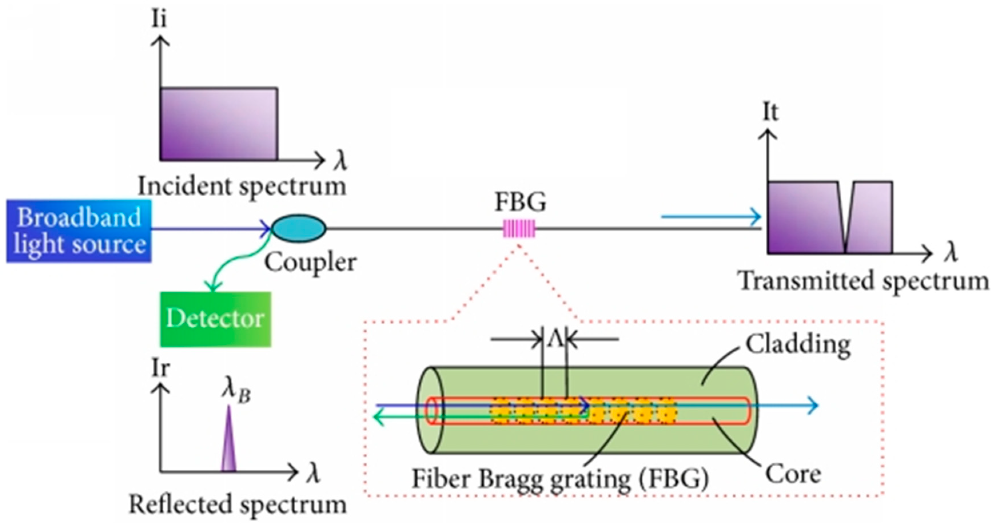
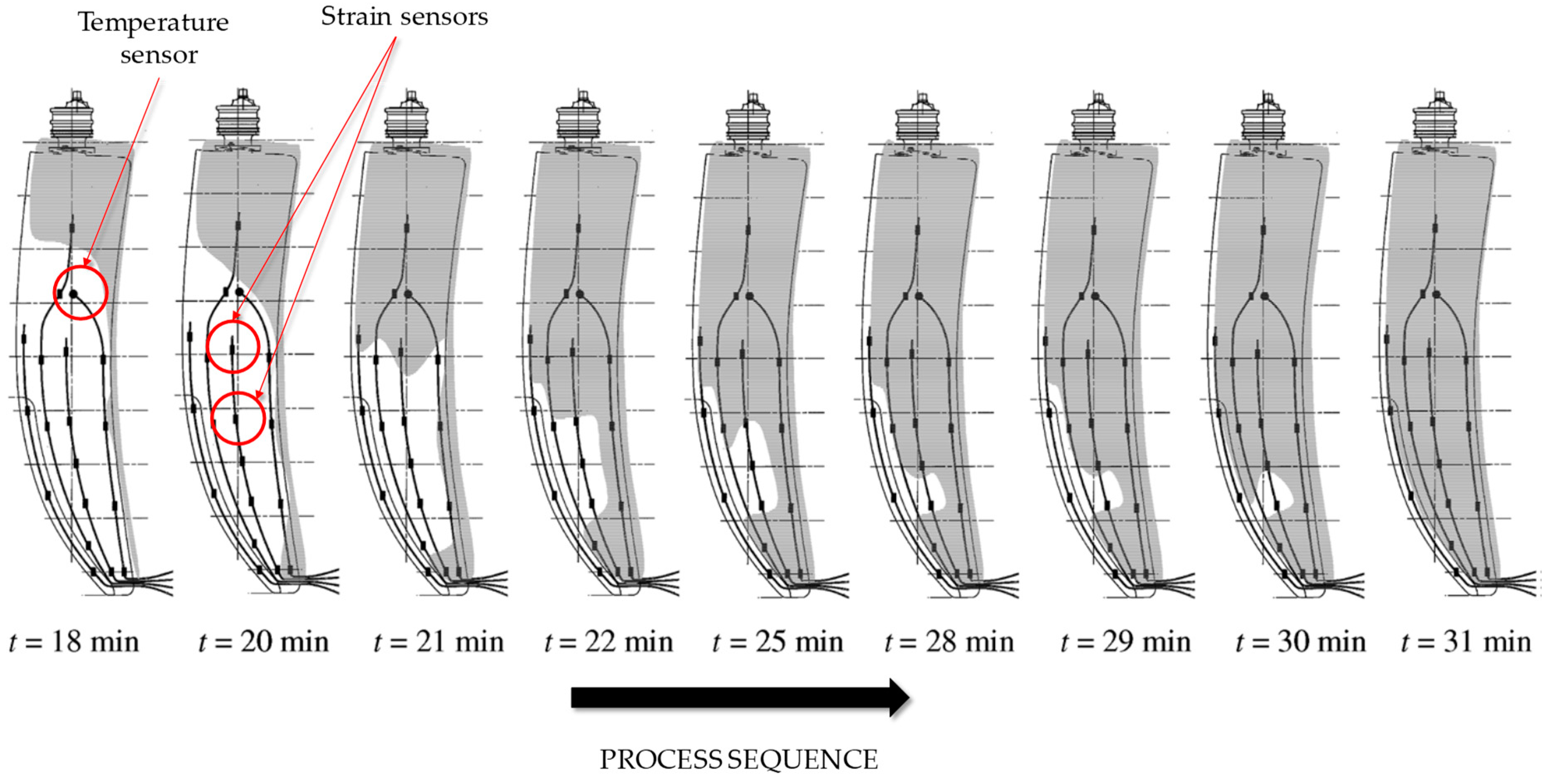
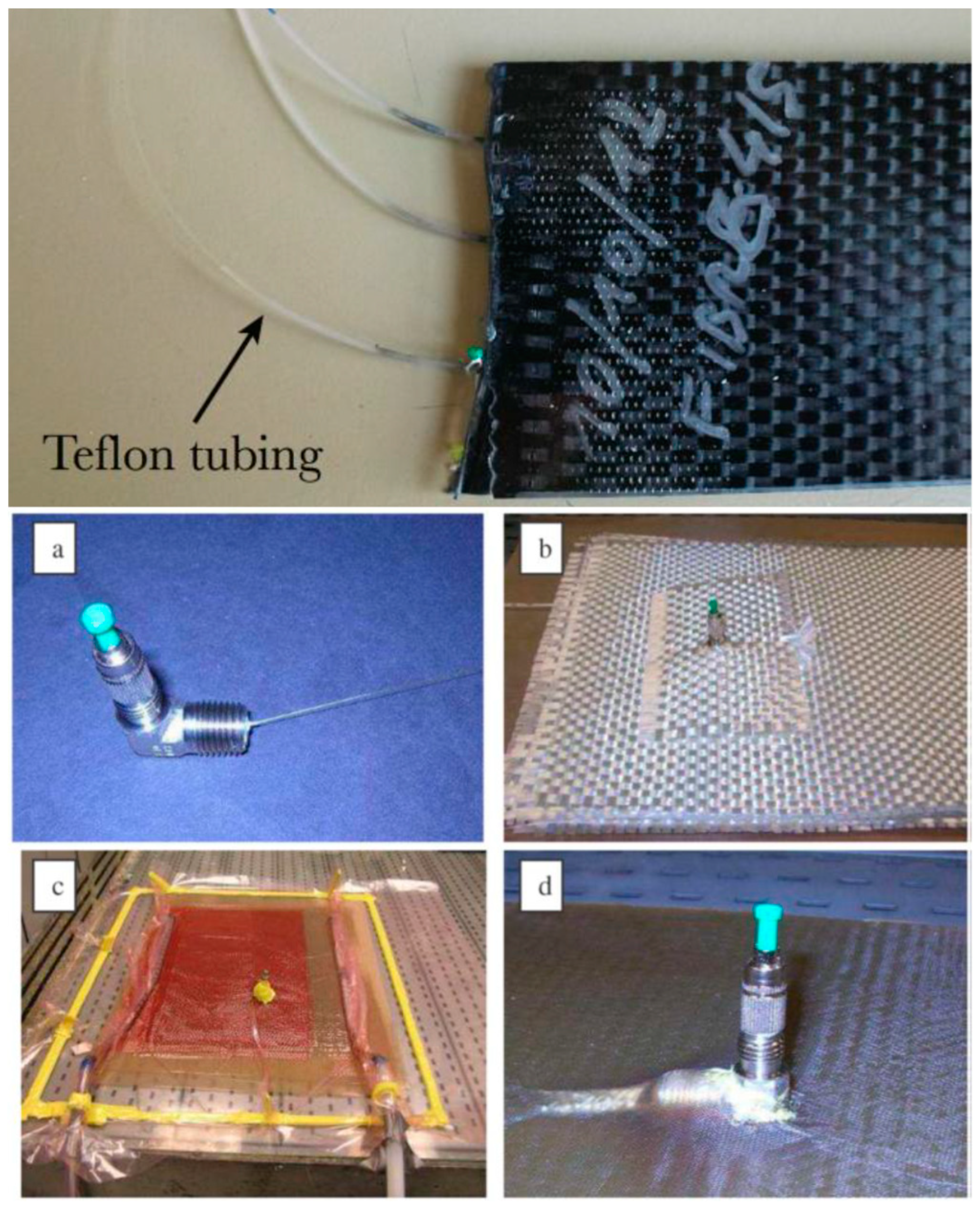
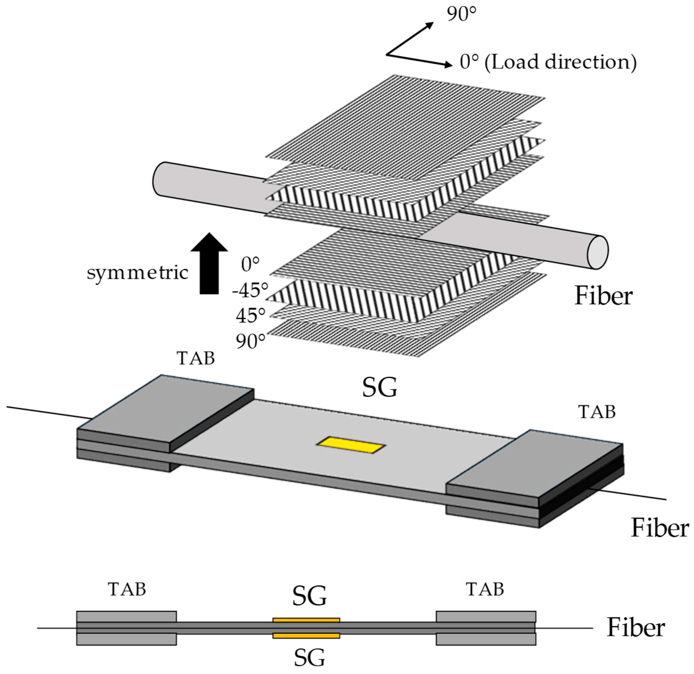
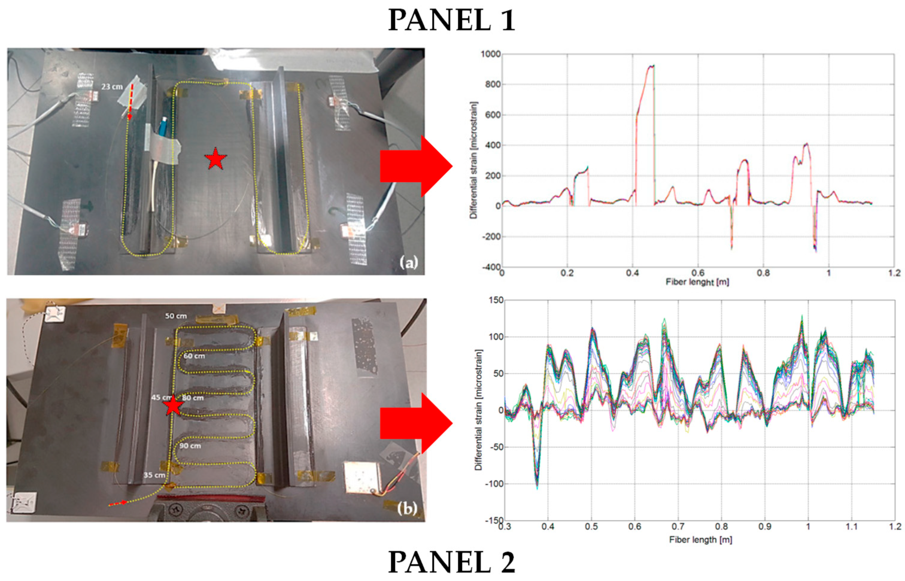
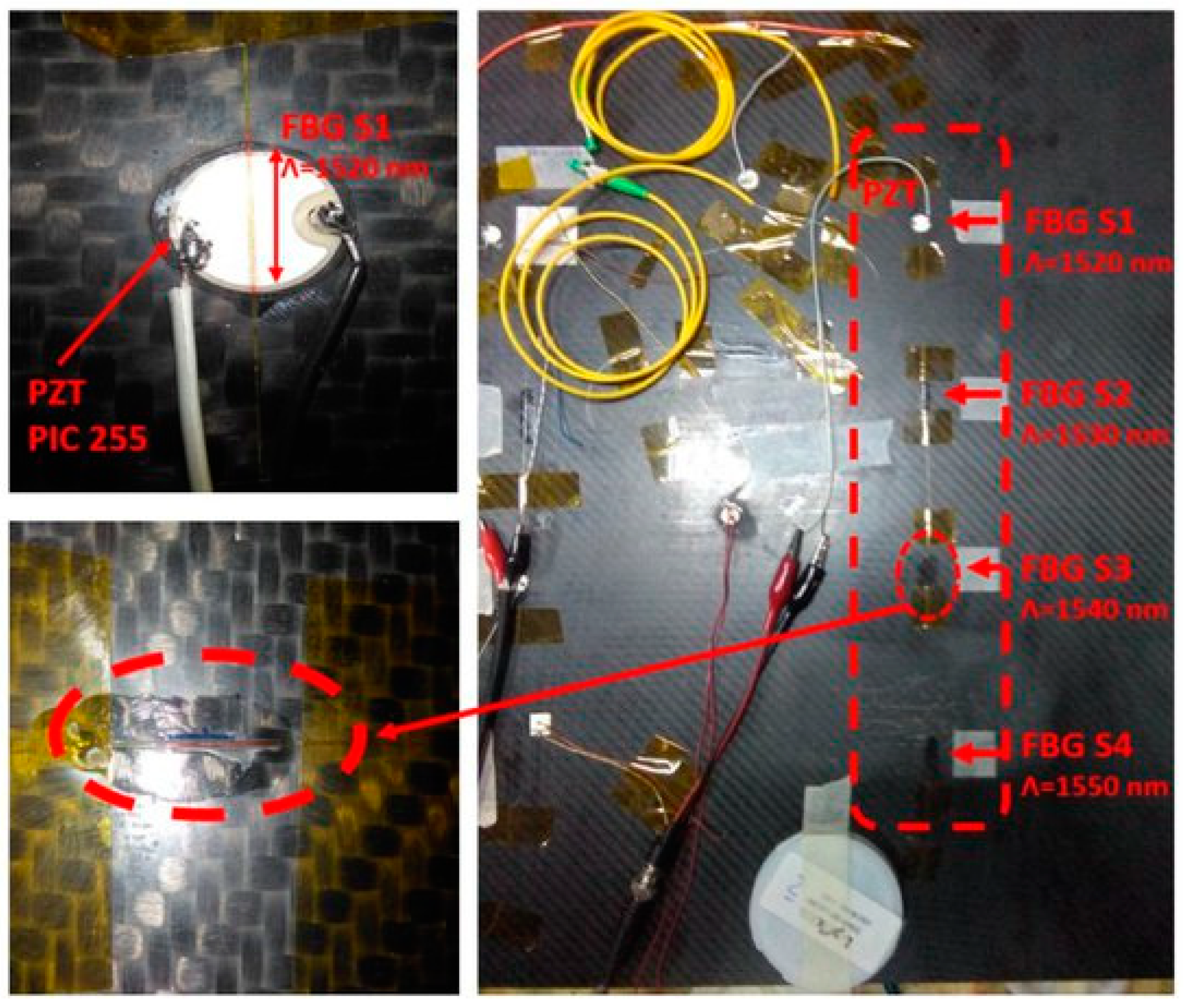
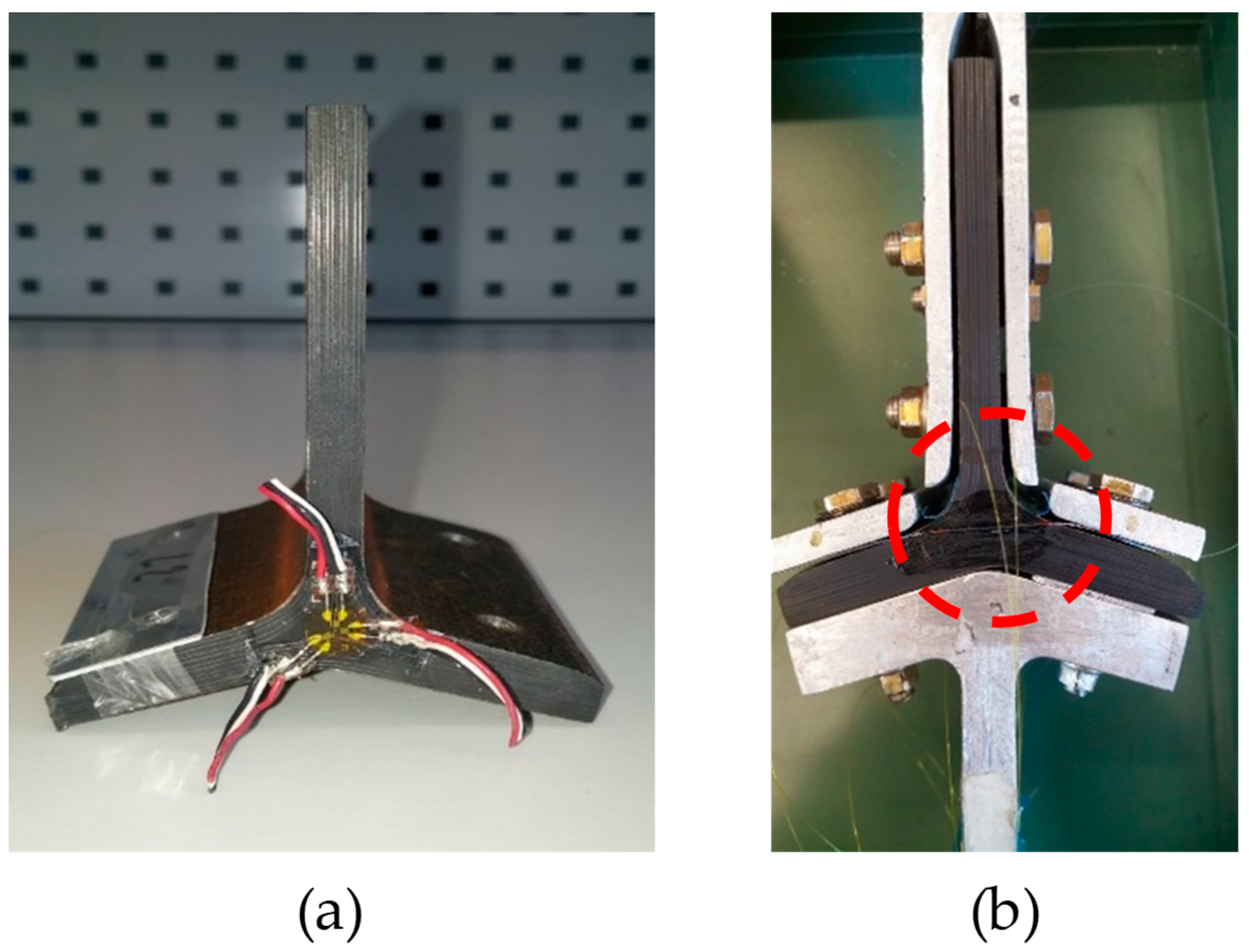
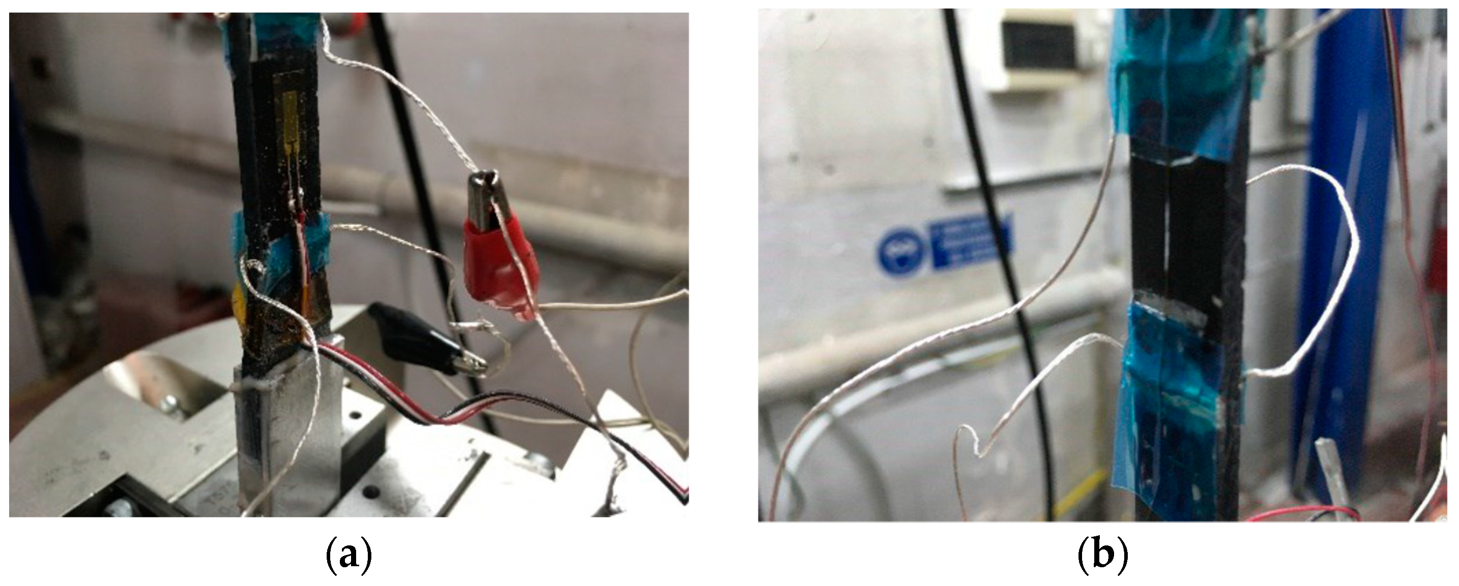
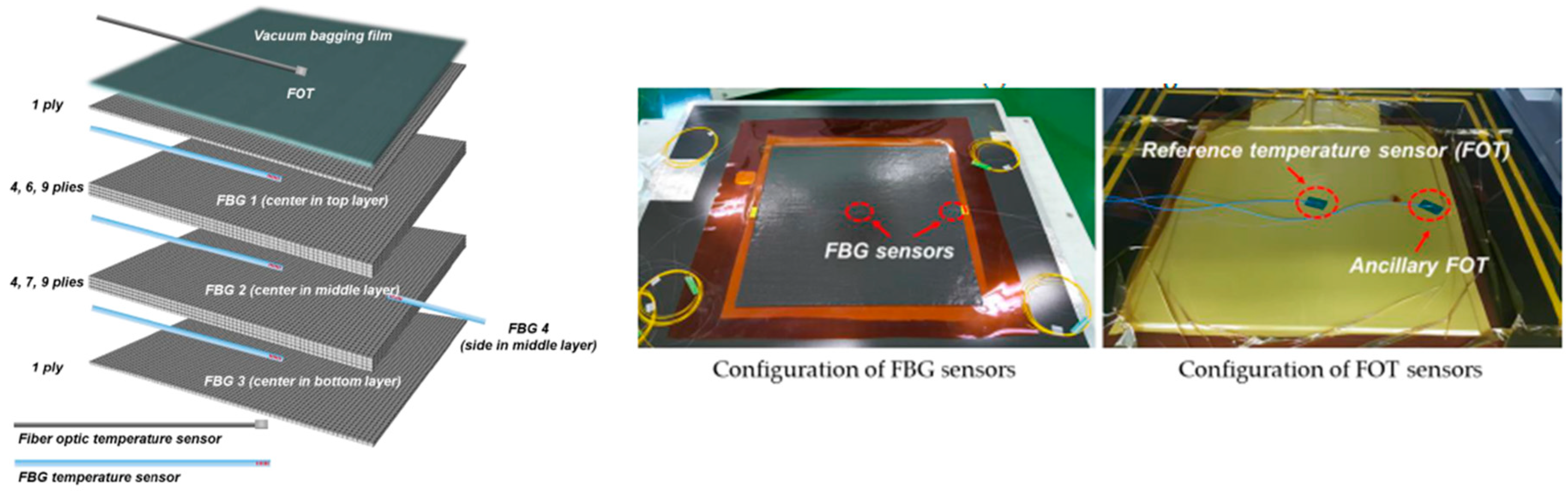
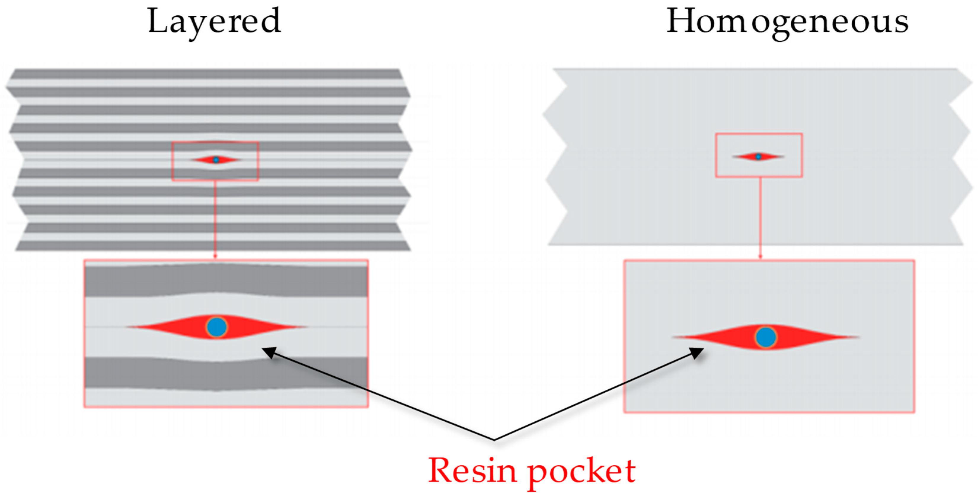
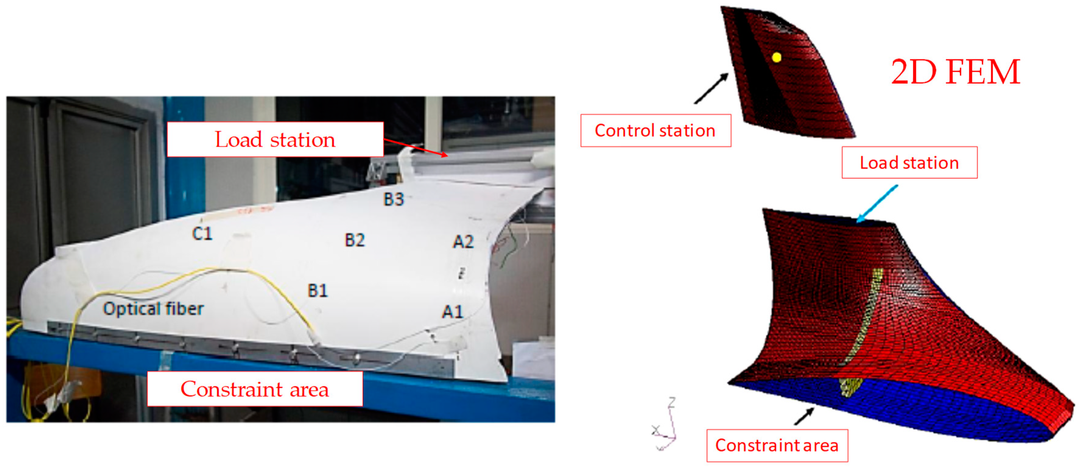
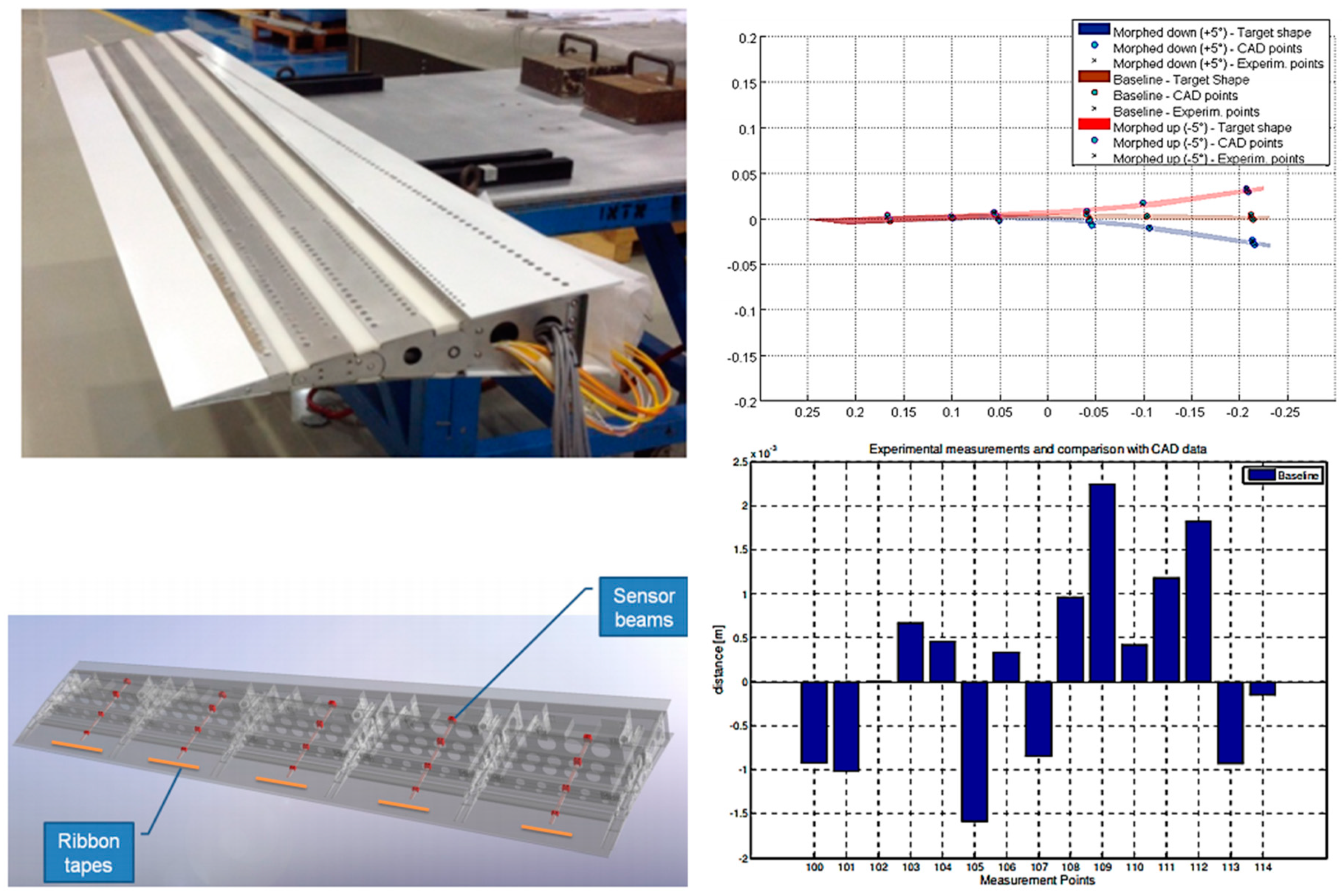
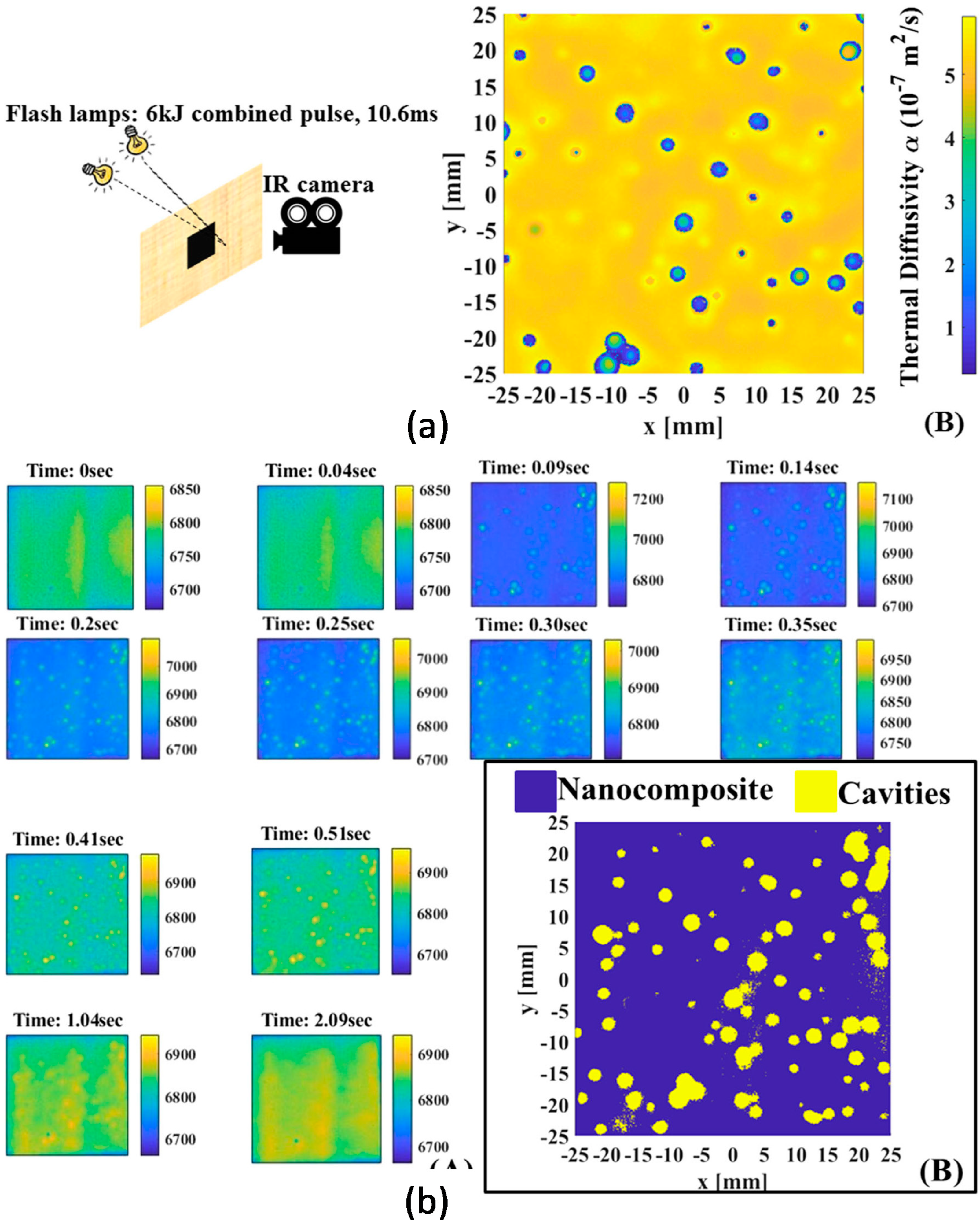
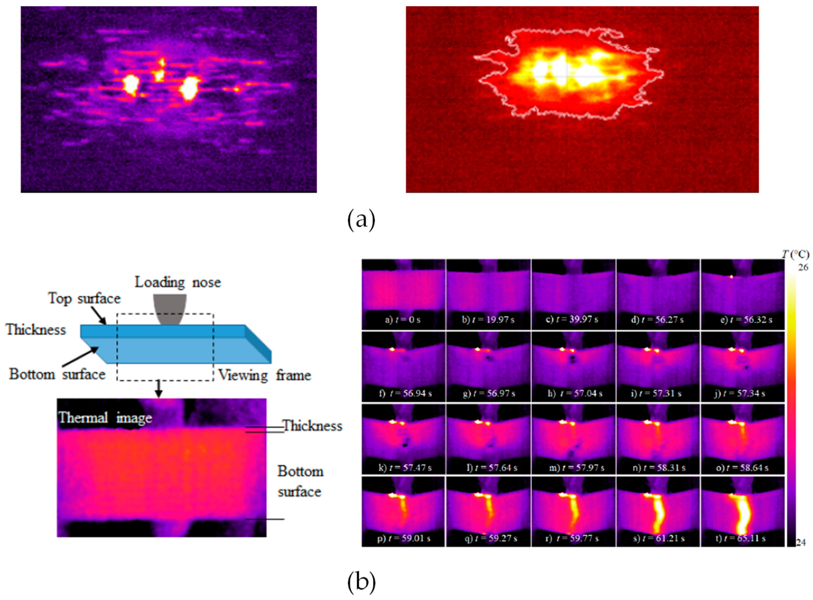
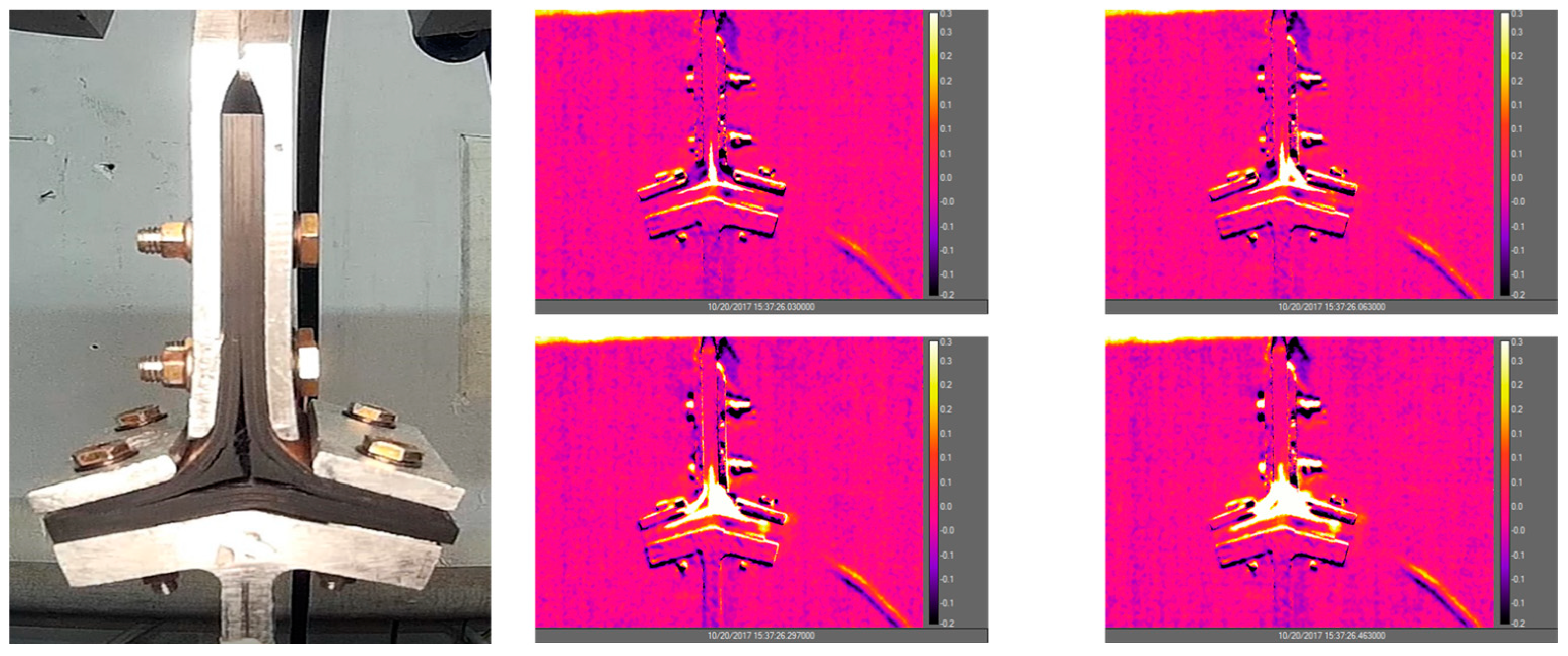
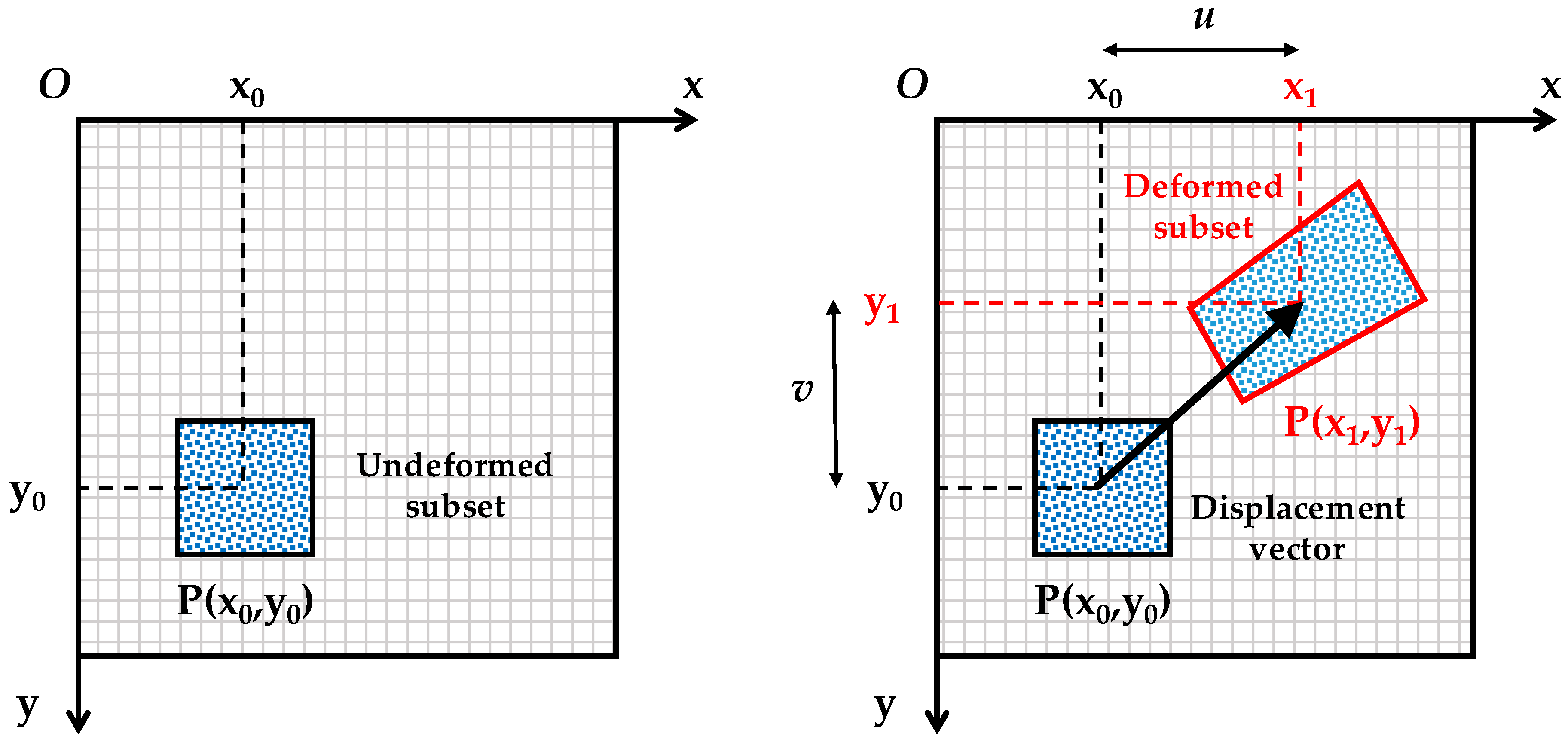
Table 1.
Summary of active infrared thermography (IRT) methods [114].
Table 1.
Summary of active infrared thermography (IRT) methods [114].
| Physical Principle | Thermal Source | Active IRT Terminology | |
|---|---|---|---|
| Optical radiation | Optical flash, lamp, and electrical heaters | Optically Stimulated Thermography (OST) | Pulsed Thermography [115] (or Flash Thermography) |
| Lock-in Thermography [116] (or Amplitude Modulated Thermography) | |||
| Step-Heating Thermography [117] and Long Pulse Thermography [118] | |||
| Optical laser | Frequency Modulated Thermography [119] | ||
| Laser-Spot Thermography [120] and Laser-Line Thermography [121] | |||
| Acoustic/ultrasonic wave propagation | Acoustic/ultrasonic horn, piezo-ceramic sensors, air-coupled transducers | Ultrasonic Stimulated Thermography [122] (or Thermosonics, Vibro-Thermography, and Sonic IR Thermography) | |
| Nonlinear Ultrasonic Stimulated Thermography [123] | |||
| Electromagnetic Radiation for dielectric materials | Induced eddy currents | Eddy Current Stimulated Thermography [124] | |
| Microwaves | Microwave Thermography [125] | ||
| Material enabled thermo-resistive radiation for composite materials | Electrical current applied to carbon fibres | Direct Material-Based Thermography (DMT) | Electrical Resistance Change Method (ERCM) coupled to thermography [126] |
| Electrical current applied to embedded steel wires | |||
| Electrical current applied to embedded carbon nanotubes | Indirect Material-Based Thermography (IMT) | Metal-Based Thermography [127] | |
| Electrical current applied to embedded shape memory alloys wires | Carbon Nanotubes-Based Thermography [128] | ||
| Shape Memory Alloys-Based Thermography [129] | |||
© 2020 by the authors. Licensee MDPI, Basel, Switzerland. This article is an open access article distributed under the terms and conditions of the Creative Commons Attribution (CC BY) license (http://creativecommons.org/licenses/by/4.0/).
Share and Cite
MDPI and ACS Style
Arena, M.; Viscardi, M. Strain State Detection in Composite Structures: Review and New Challenges. J. Compos. Sci. 2020, 4, 60. https://0-doi-org.brum.beds.ac.uk/10.3390/jcs4020060
AMA Style
Arena M, Viscardi M. Strain State Detection in Composite Structures: Review and New Challenges. Journal of Composites Science. 2020; 4(2):60. https://0-doi-org.brum.beds.ac.uk/10.3390/jcs4020060
Chicago/Turabian StyleArena, Maurizio, and Massimo Viscardi. 2020. "Strain State Detection in Composite Structures: Review and New Challenges" Journal of Composites Science 4, no. 2: 60. https://0-doi-org.brum.beds.ac.uk/10.3390/jcs4020060