Article

Determination and Validation of Residual Stresses in CFRP/Metal Hybrid Components Using the Incremental Hole Drilling Method

1
Institute of Materials Engineering, University of Kassel, Mönchebergstr 3, 34125 Kassel, Germany
2
Institute for Lightweight Design with Hybrid Systems, University of Paderborn, Mersinweg 7, 33100 Paderborn, Germany
*
Author to whom correspondence should be addressed.
J. Compos. Sci. 2020, 4(3), 143; https://0-doi-org.brum.beds.ac.uk/10.3390/jcs4030143
Submission received: 19 August 2020 / Revised: 15 September 2020 / Accepted: 17 September 2020 / Published: 21 September 2020
(This article belongs to the Special Issue Metal Composites)

Abstract

:
Lightweight materials contribute to an efficient decrease in fuel consumption in the automotive and aircraft industries. Hybrid components made of metal and carbon fiber-reinforced plastics (CFRP) have a high potential in lightweight applications due to their high strength-to-weight ratio. For cost-effective processing of hybrid materials, advanced manufacturing processes such as the prepreg-press-technology have been developed, in which the bonding between a metallic component and a fiber compound is exclusively realized in the forming process. However, upon processing of these hybrid components at elevated temperature, the difference in thermal expansion coefficients of the two materials leads to the formation of tensile residual stresses upon cooling. It is well known that these tensile residual stresses can be detrimentally effective with respect to the durability of a hybrid component. The objective of this work is to accurately measure and analyze residual stresses in hybrid components made of unidirectional CFRP and steel through the incremental hole drilling method. Within this study, the evaluation formalism for orthotropic materials is employed for measuring non-uniform residual stresses in hybrid materials. In order to improve the measurement accuracy, a customized strain gauge with eight grids is employed and a drilling increment size of only 20 µm is utilized. The influence of the angle between the strain gauge rosette and the fiber direction on the evaluation of the residual stresses is investigated. In order to evaluate the reliability of the results determined, a bending test applying a well-defined load is carried out. By direct comparison of the experimentally determined stresses and stress values calculated by the finite element method, the applicability of the hole drilling method for robust determination of residual stresses in CFRP/metal hybrid components is finally validated.

1. Introduction

In light of the demand for reducing the emission of climate-damaging gases such as CO2, it is very important to apply lightweight materials in the automotive and aerospace industries. Due to their superior weight-specific mechanical properties, carbon fiber-reinforced plastics (CFRP) are highly favorable in aerospace and automotive applications. However, their brittle failure behavior limits their structural integrity and damage tolerance in the case of impact and crash events, respectively [1]. Metallic materials are comparatively ductile, but much heavier. In recent years, hybrid components and structures made up of metal and CFRP have received increasing attention as two types of materials that can be combined in a manner to offset the drawbacks of every single material and an optimum with respect to mechanical properties can be reached. Thus, hybridization allows for tailoring components with desirable mechanical performance. Furthermore, in the automotive industry, hybrid components can be easily integrated into available vehicle production processes and existing body structures, respectively, as their metallic surfaces enable conventional joining, e.g., spot welding and clinching.
Hybridization of the metallic component and the CFRP can be mainly achieved through four different approaches. The hybridization can be realized by separate forming of the metallic component and manufacturing of the CFRP part, followed by joining using adhesives [2]. However, this kind of approach requires an overall long processing time [2]. It is well known that the metallic component and the CFRP can be joined by various other downstream processes, such as riveting and screwing. However, these approaches create additional weight and may lead to fiber damage [3,4]. Welding enables the joining of CFRP and metal as well. Upon welding, the partial melting of the matrix material within the CFRP leads to adhesive bonding and interlocking to the metal surface [5]. However, this process needs additional efforts and may yield local defects due to high temperature [3]. Alternatively, the manufacturing of hybrid materials can be realized in a one-step process, also referred to as intrinsic manufacturing, where the hybridization of different materials is exclusively realized by the forming process of the metallic and the CFRP component. Intrinsic manufacturing offers a fast and direct way of fabricating hybrid components and structures without the necessity of subsequent joining processes. A review on various technologies of joining of CFRP and metals can be found in [3].
Based on the advantages mentioned above, intrinsic manufacturing is used in the present work for fabricating CFRP/metal hybrid components. Upon manufacturing, the difference in thermal expansion coefficients of the dissimilar materials, the chemical shrinkage of the CFRP as well as the temperature gradient lead to deflection and to the formation of tensile residual stresses, respectively [6]. These residual stresses can have detrimental effects on the mechanical properties of the hybrid component and structure and can cause defects such as delamination, part failure due to geometric distortion, built-in cracking or premature failure of parts subjected to alternating loading or corrosive environments [6]. The formation of residual stresses can be controlled by a variety of extrinsic and intrinsic parameters, such as process temperature and pressure, material properties and thickness of the samples. Clearly, optimizing process parameters is needed to reduce the process-induced residual stresses. As a consequence, reliable residual stress measurement tools are required for the establishment of a thorough knowledge based on the relations between the process parameters and the residual stresses.
The measurement of residual stresses can be generally classified as non-destructive, semi-destructive and destructive. Each method has its own advantages and limitations. The measurement of residual stresses in metallic materials has been subject of research for many years. The most widely used non-destructive method is X-ray diffraction (XRD), which is capable of providing reliable near-surface residual stress measurements in crystalline materials. However, this technique falls short in the determination of residual stresses in CFRP and hybrid components. This limitation holds true for synchrotron and neutron diffraction techniques. A well-established semi-destructive approach is the hole-drilling method (HDM), which has been standardized in ASTM E837-13a [7]. This standard describes relevant details of the process, e.g., the correct attachment of the strain gauge rosette and the correct procedure for drilling a hole for relieving the residual stresses as well as the determination procedure needed for the calculation of the original residual stresses from the measured strains. The HDM is capable of providing reliable in-depth residual stress results and can be applied to various materials, such as metals [7] and polymers [8], as well as composites [9,10,11]. Many studies compared the residual stresses in metallic materials measured by XRD and HDM [12,13]. The reliability of the residual stress measurement through HDM can be validated by mechanical bending tests [8,14,15]. In addition, in terms of application the damage caused to the sample is localized to the small hole and, thus, is often tolerable or repairable such that the method is referred to as a semi-destructive approach. Furthermore, destructive methods such as the slitting method [16] and the layer removal method [15] were employed to measure the residual stresses in composite and laminates. However, these methods not only completely destroy the samples, but also were shown to provide results with a relatively low accuracy and spatial resolution, respectively.
The difficulty in measuring the residual stresses in hybrid components is justified in the characteristics of the composite as well as in the interfacial zone between the metal and the composite, i.e., an abrupt change in the material properties. In recent years, progress has been made with respect to the residual stress measurement not only in the composite itself but also in hybrid materials. In [9], the residual stress distribution in laminates [02/θ2]s (θ = 0°, 30°, 45°, 60°, 90°) was measured through the HDM based on the assumption that the relieved strain response has a simple trigonometric form. Clearly, this assumption does not hold true for orthotropic materials. Afterwards, a new model was proposed in [17] for orthotropic materials using a mathematical solution for the displacements around a hole in a stressed orthotropic plate, which was used for determining the relationship between the residual stresses and the strains relieved by hole-drilling. The model proposed in [17] was extended to the incremental hole-drilling method for being capable of determining non-uniform residual stresses in laminated composites [9,18,19] and FRP/metal laminates [20]. However, some limitations were presented in a previous work: (i) only the plane elastic constants (Ex, Ey, νxy, Gxy) were used in the finite element analysis for calculating calibration coefficients; (ii) each ply was drilled with one increment; (iii) the measured residual stress results have not been validated. Very recently, Magnier et al. [11,21] adopted a solid element with nine elastic constants Ex, Ey, Ez, νxy, νxz, νyz, Gxy, Gxz, Gyz, in the finite element analysis/method (FEA/FEM) for calculating calibration parameters with the goal of better describing more complex and realistic stress profiles in hybrid composites. The proposed methodology was applied for measuring residual stresses in unidirectional CFRP and the reliability of the results has been validated by mechanical bending tests [11,21].
The difference in thermal expansion coefficients between the composite and the metal can yield relatively large residual stresses. Hence, this topic recently gained significant attention in industry due to the demand for lightweight constructions. However, data as well as studies reported in open literature are limited so far. In [6], a cure monitoring system based on fiber Bragg grating (FBG) sensors was used to measure the in-plane strains during processing of CFRP-steel laminates after the calibration of the bare fiber Bragg sensor. The measured strain was then used to calculate residual stresses by using the classical laminate theory (CLT) approach. However, the mechanical properties of the sample during the curing process were steadily changing and, thus, led to errors in estimating the residuals stresses. Moreover, the adopted CLT for evaluating the residual stresses relied on many assumptions. As reported in [22], an error of up to 25% has to be expected when residual stresses are calculated based on the original CLT.
In the present work, the incremental HDM is extended and applied for determination of residual stresses in hybrid components made up of steel and unidirectional CFRP being realized by intrinsic manufacturing. A novel formalism for in-depth non-uniform residual stress analysis in orthotropic materials is adopted and a solid element with nine elastic constants in FEA is utilized for calculating the calibration coefficients. In order to improve the measurement accuracy and precision in the determination of the relieved strain, a customized strain gauge with eight grids and a small drilling increment of 20 µm are utilized. To validate the residual stress measurements, a mechanical bending test inducing well-defined stress states is carried out. Through the HDM, the measured residual stresses are compared to stress values calculated by FEA. The present paper is arranged as follows: the paper firstly introduces the methodology of the incremental HDM used for residual stress measurement in orthotropic materials detailing information on the novel evaluation formalism according to [18], as well as on the approach of calculating the coefficients in FEA. In Section 3, the experimental set-up for manufacturing the hybrid composites is shortly introduced. Afterwards, the experimentally determined strain values and the evaluated residual stresses on the CFRP and metal sides are presented. The reliability validation for the residual stress measurement based on the bending test is detailed in Section 3 as well. Finally, in Section 4, discussion on the findings is concluded and potential future work is highlighted.

2. Methodology of Incremental HDM in Orthotropic Materials

This section introduces the theory of incremental HDM for in-depth non-uniform residual stress analysis in orthotropic materials including the evaluation formalism and the approach of calculating the coefficients based on FEA. All basic considerations have been detailed and discussed for a single layer CFRP in [11,21]. To allow for direct evaluation of the results obtained in the present work, the key part of the theory is summarized in the following.
According to ASTM E837-13a [7], the incremental HDM involves the incremental drilling of a small hole in a component within the geometrical center of a strain gauge rosette. After the removal of each layer of material, a new equilibrium is established around the hole. The in-depth non-uniform stress profile can be determined relating the relieved strain with the previously existing stresses in each depth increment throughout the total hole depth. Figure 1 shows a sketch of a typical strain gauge and the coordinate system used for analysis, where the positive X direction is alongside the axis of strain gauge 1 and the negative Y direction alongside the strain gauge 3.
However, this standard is only applicable for isotropic materials. For measuring the residual stress in composites and hybrid components with distinct anisotropy, the relieved strain and the residual stress can be related through
( ε 1 ε 3 ε 2 ) = [ C 11 C 12 C 13 C 21 C 22 C 23 C 31 C 32 C 33 ] · ( σ x σ y τ x y ) = [ C ] · ( σ )
where ε 1 , ε 2 and ε 3 are the strains determined by a strain gauge with three grids at known positions, and σ x , σ y and τ x y are the in-plane stress components—see Figure 1. Equation (1) is based on the following assumptions: the material has a linear elastic behavior and the residual stress is uniform in the sample neglecting the stress gradient alongside the through-thickness direction. For measuring the residual stress in fiber-reinforced composites, the strain gauge 1 should always be in the fiber direction X, while the strain gauge 3 should be in the transverse direction Y (Figure 1). Please note that Cij in Equation (1), which is a function of material properties rather than being equivalent to material properties, reveals the relation between the relieved strains and the existing residual stresses. The coefficients C11, C21 and C31 can be obtained by imposing a uniform stress value σx. For calculating the calibration coefficients C12, C22 and C32, a load can be applied in the y direction, and by imposing the in-plane shear load, calibration coefficients C13, C23, and C33 can be calculated. The calibration coefficients are required for evaluating the residual stresses in the integral form, which then will be calculated through FEA—see the following parts of the text for more details.
As described in ASTM E837-13a [7], the incremental HDM enables us to determine in-depth non-uniform residual stress profiles in through-thickness direction of the sample. In such a case, the relieved strain within the ith increment is the final effect of residual stresses of all previous drilled increments, which can be determined by a superposition expression through
( ε ) i = ( ε 1 ε 3 ε 2 ) i = j = 1 i [ C 11 C 12 C 13 C 21 C 22 C 23 C 31 C 32 C 33 ] i j · ( σ x σ y τ x y ) j ,        1 j i
with the assumption that the residual stress state within each increment is uniform. Each matrix [C]ij in Equation (2) for evaluating residual stresses is composed of 9 coefficients Ckl. The coefficient Cklij inside the matrix [C]ij depends not only on the residual stress σj in the present jth increment, but also on all the residual stresses which were present in all previously drilled i increments.
Equation (2) can be solved in an iterative manner
( σ x σ y τ x y ) i = [ C 11 C 12 C 13 C 21 C 22 C 23 C 31 C 32 C 33 ] i i 1 · ( ( ε 1 ε 3 ε 2 ) i j = 1 i 1 [ C 11 C 12 C 13 C 21 C 22 C 23 C 31 C 32 C 33 ] i j · ( σ x σ y τ x y ) j )
The readers are referred to [8,14,21] for more details on the methodology used for evaluating the residual stresses applying the incremental HDM for orthotropic materials.
Pronounced local heterogeneity and defects such as pores and small cracks can be present in the material. Moreover, the material may be damaged due to the drilling procedure itself. In order to obtain sufficient strain information in different directions during one drilling process, minimizing the errors induced by the factors mentioned above, a special strain gauge with eight grids was employed in the present work. The utilized eight-grid strain gauge and the position of the grids 1 to 8 are shown in Figure 2a. Note that only the strain information of three grids from the strain gauge is required for the residual stress evaluation. Figure 2b illustrates eight different combinations of strain gauge grids adopted in the present work. By direct comparison of the strains determined and the calculated stress distributions from different strain gauge combinations, information regarding local heterogeneity and defects can be deduced. Eventually, the optimal combination of strain gauges could be established based on this approach. For measuring the residual stresses in CFRP, the strain gauges 1 and 5 were always aligned with the carbon fiber direction X. The choice of the orientation between the fiber and the strain gauge affects the reliability of the stress results, as was already shown in [11].
The strains measured at the surface of the sample cannot directly be related to the stress existing at a given depth. According to ASTM E837-13a [7], the integral method is a very reliable method, enabling to determine the relation between the relieved strain and the residual stress. For application of the integral method, the calibration coefficients are required, which can be determined by numerical simulation through FEA. In the present work, a three-dimensional finite element model was used for the determination of the calibration coefficients based on ABAQUS/Standard with elements of type C3D8R, where the material is considered to be linear elastic. Figure 3a shows a cylindrical model with the hole diameter of 2 mm and the outer diameter of 50 mm, which is composed of about 200,000 eight-node solid elements of type C3D8R including local mesh refinement in direct vicinity of the drilled hole. The model is characterized by homogeneous orthotropic material properties, and the ply orientation is defined in a local coordinate system. The in-plane stress components σ x , σ y and τ xy are converted to σ r and σ r θ in a radial coordinate system for prescribing the loads at the hole boundary, eventually enabling the application of a defined stress state equivalent to the released stresses within an increment during the drilling process (see Figure 3b). The imposed mechanical boundary conditions at the bottom surface of the sample are given in Figure 3c, where the circular boundaries are fixed in all directions, while the part of the model below the hole is not fixed. The reason for employing such a kind of mechanical boundary conditions was explained in detail in [14]. For the CFRP part, a unidirectional ply is considered as being characterized by homogeneous orthotropic material properties, where the ply orientation is defined in a local coordinate system. In the FEA the material was removed using the “Remove” function implemented in a Python script. This tool allows to delete all elements from a part representing the procedure experimentally implemented in the incremental drilling process.
For obtaining the whole [C]ji matrix in Equation (2), the effects of σx, σy and τ xy on ε are considered separately. The first column of [C]ij can be determined by only considering the stress σx, the second column considering the stress σy, and the last column based on the shear stress τ xy. As described above, the loads are prescribed in a radial coordinate system at the side surface of the hole within each increment for calculating the coefficients in the FEA. More information on the calculation of the coefficients for FEA of orthotropic materials can be found in [8,14]. In the present study, the interface between the two materials of the hybrid component, i.e., the CFRP/metal interface, was not assessed due to the thickness of the CFRP and metal parts, which is well above the application range of the HDM (being up to 800 µm). Instead, the holes were drilled on the surface of the two sides of the component separately for determination of the residual stresses (see Section 3 for more details). Furthermore, the metal part was considered to be isotropic and fully elastic. Thus, the standard formalism and approach, respectively, was applied for the metal part. As numerous publications on this topic are available [7,14], further explanation is not provided in the present work. Relevant material properties of the two materials in the hybrid component are given in Table 1.
From the calculation procedure detailed above, it is evident that the calibration parameters are only valid for the given hole geometry, the type and position of the strain gauge, as well as the material properties of the hybrid component considered. Hence, once any of the above mentioned parameters is changed, the calibration model needs to be updated so as to generate a correct calibration coefficients profile. In the present work, the CFRP and steel sides in the hybrid composite sample were measured through HDM, respectively. Therefore, the calibration coefficients of both sides are required to be calculated accordingly. For the CFRP side, the aforementioned model is utilized for calculating the calibration coefficients, whereas the formalism for isotropic material is employed for the calculation of the calibration coefficients on the metal side [14].

3. Experiments and Results

3.1. Prepreg-Process

The prepreg-process is a widely used intrinsic manufacturing processes allowing to efficiently fabricate hybrid components made of metal and CFRP. The experimental setup employed is shown schematically in Figure 4. In the present work, for prepreg-processing an already formed steel sheet with a thickness of 2 mm was inserted into a heated die with the dimension of 100 mm × 250 mm, and the already prepared unidirectional carbon fiber prepregs with a thickness of 2 mm (9 plies) were pressed onto the sheet metal by a heated punch. A pressure of 0.3 MPa and a temperature of 160 °C with a constant curing process time of 18 min were employed. As the epoxy resin acts as an adhesive, the joining and hybridization of sheet metal and CFRP, respectively, is realized during the curing of the CFRP. Due to the difference in thermal expansion coefficients of steel and CFRP, the formation of residual stresses is observed upon cooling. The types of carbon fiber prepregs and steel are C U255-0/NF-E322/37% with a resin content of 37% and HC340LA (micro alloyed steel), respectively. The epoxy resin acts as an adhesive to bond the fibers and the matrix as well as the metal and the CFRP by the curing of CFRP. Before manufacturing, the surface of the metal side was processed by sand blasting for increasing the surface roughness of the metal, such that the interlocking between the metal and the CFRP can be improved. After manufacturing, the surface roughness values of CFRP and metal sides were measured and the results are Ra 12.5 μm and Ra 23.6 μm, respectively. Figure 5a highlights the dimensions of the parts used for determination of residual stresses through the HDM method, which were cut from the fully processed plates. Furthermore, Figure 5b illustrates the deformation of the sample induced by the residual stresses after the sample was removed from the mold and then cut from the fully processed plate. Note that the steel sample before hybridization was not curved.
Figure 6 shows a cross-sectional view highlighting the microstructure of the hybrid sample obtained by using a digital microscope. From this micrograph, a good bonding between the CFRP and the steel can be deduced. The sample for microstructure visualization was cut alongside the longitudinal fiber axis. However, within single plies of the CFRP, the fibers are not perfectly straight and aligned. This is assumed to lead to scatter and will be analyzed and discussed in the remainder of the work.

3.2. Residual Stress Measurement

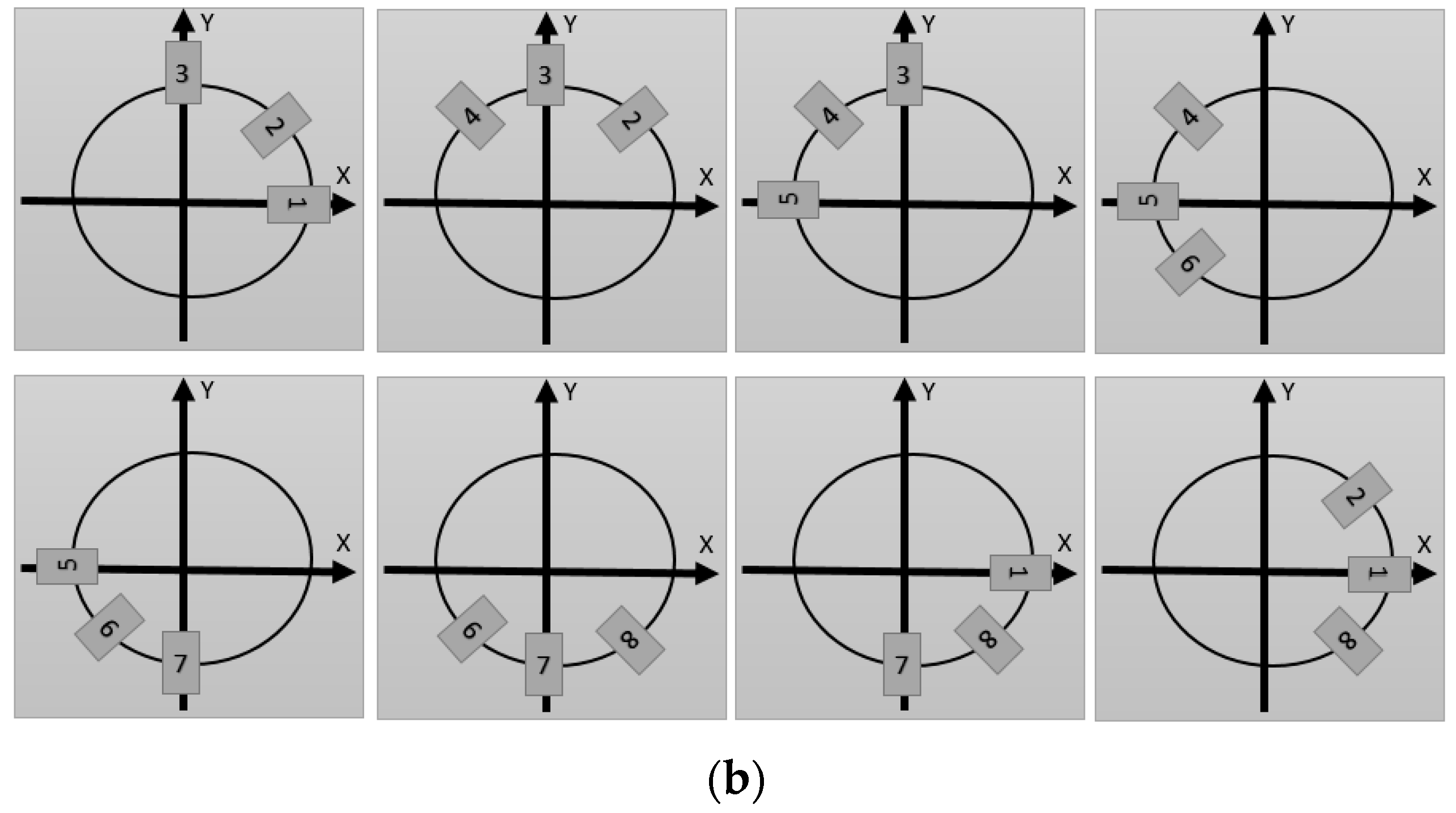
In the present work, the residual stresses are measured through the HDM on both sample surfaces, i.e., the CFRP and steel sides separately. Due to the individual thickness of the CFRP and the metal (2 mm each), the residual stress information at the interface between the CFRP and the metal cannot be directly determined through the HDM. The strain gauge is attached to the surface of the sample through adhesives and is further covered with a coating for preventing debonding during the removal of the foil in the center of the strain gauge caused by the drilling tool. As mentioned in the previous section, for improving the reliability of the measurements a strain gauge with eight grids manufactured by Höttinger Baldwin Messtechnik (HBM, Darmstadt, Germany) is used for measuring the strain in the CFRP, and eight combinations of strain gauge grids are employed (cf. 
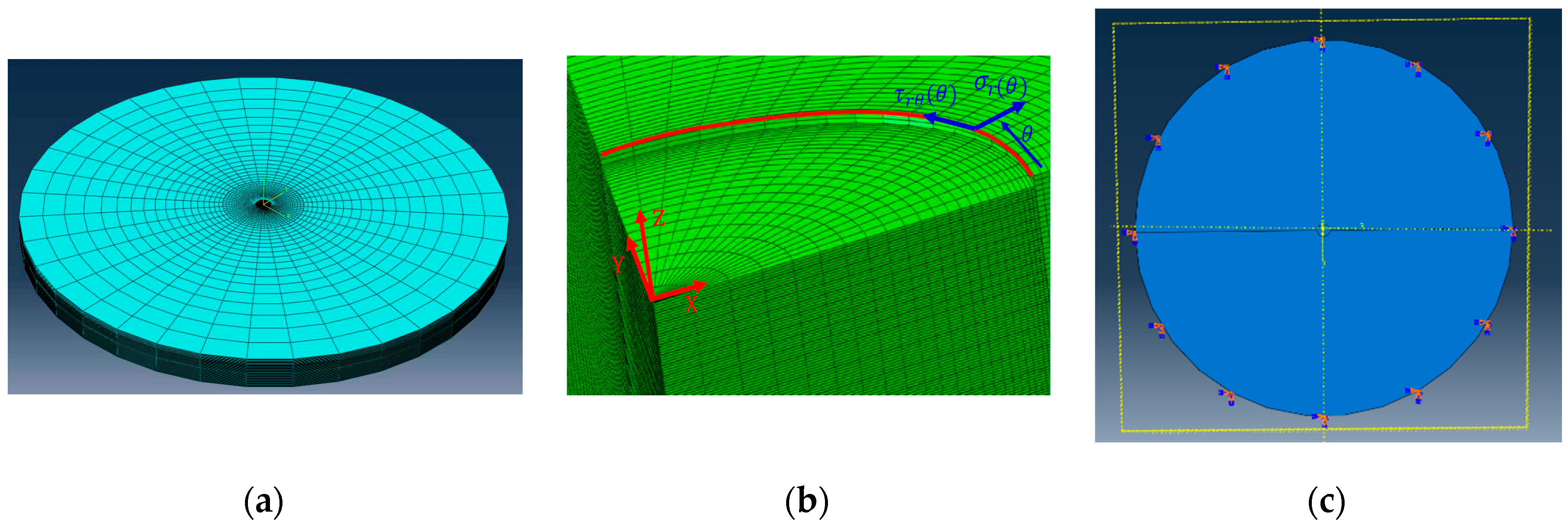
Figure 2b). The full measurement range of the strain gauges is ±3%. The standard Vishay CEA-XX-062UM-120 strain gauge with three grids is employed to measure the strain in the steel. This is regarded to be sufficient at this point due to the isotropic material properties of the steel considered. The strain gauge is connected to a quarter bridge with a feeding voltage of 1 V for the CFRP and a feeding voltage of 3 V for the steel. A tool made of carbide tungsten (ref H2.010, Komet) is used for drilling. With respect to the general theory, a small drilling step size was considered in order to meet the basic assumption that the residual stress is uniform within each drilling step, eventually giving more accurate results. However, this procedure significantly increases the processing efforts. In the present work, the hole is drilled incrementally with a step size of about 20 µm in order to provide for a reasonable compromise between accuracy and processing time. The waiting time between the successive drilling steps is adjusted to 2 min for ensuring the stability of the recorded strain data before conducting the next drilling step. During the drilling process, an air turbine is used to drill the hole with a drilling speed of about 300,000 rpm (3 bar) combined with the orbital technique, which enables the chip to freely move out of the hole, avoiding inducing new stresses in the material. Due to this technique, a hole of sufficiently good quality can be achieved [23].
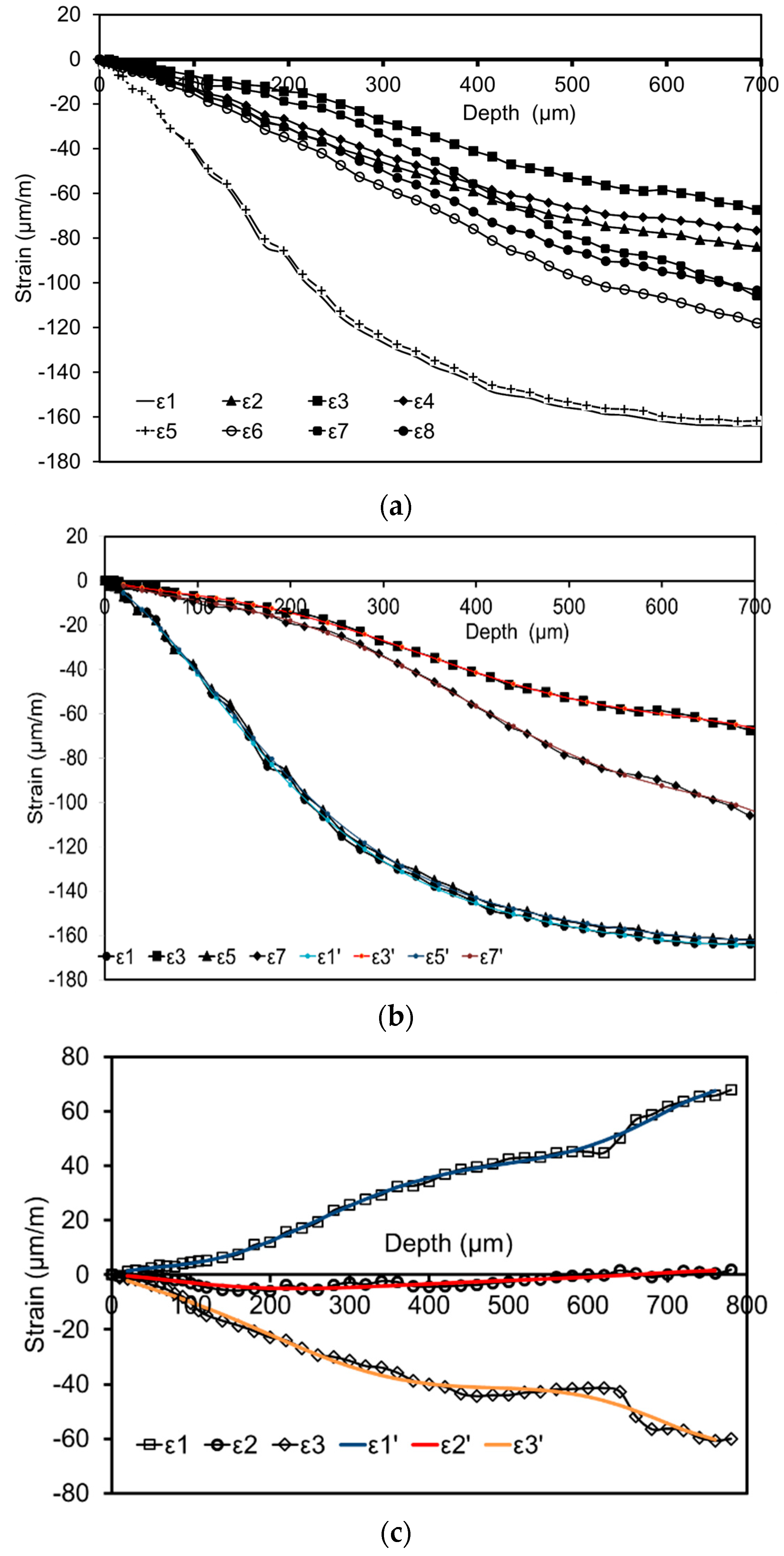
Figure 7a highlights the results of the strain measurements on the side of the CFRP using the special strain gauge. Obviously, the strain values increase as the drilling depth increases due to the release of the residual stresses. Please note that the strain gauges 1 and 5 are aligned in the fiber direction, while the strain gauges 3 and 7 are aligned transverse to the fiber direction. It is seen that the relieved strains in the directions of 1 and 5 are very close and significantly higher as compared to the other directions. This can be rationalized based on the fact that they are aligned in the fiber direction. For calculation of calibration coefficients using FEA, the increment thickness and size are fixed, which may not perfectly match the real drilling process. Therefore, an approximation function fitted to the measured strains is required for final evaluation of the residual stresses. It is obvious that the approximation accuracy determines the accuracy of the evaluation of residual stresses. Figure 7b shows the measured and approximated strains in the directions of 1, 3, 5 and 7 of the strain gauge on the CFRP side, where a polynomial function of an order of six is used to eventually obtain good approximation (the approximated strains are marked with color). Figure 7c shows the measured and approximated strains in the three directions of the strain gauge on the metal side, where the standard strain gauge with three grids is employed.
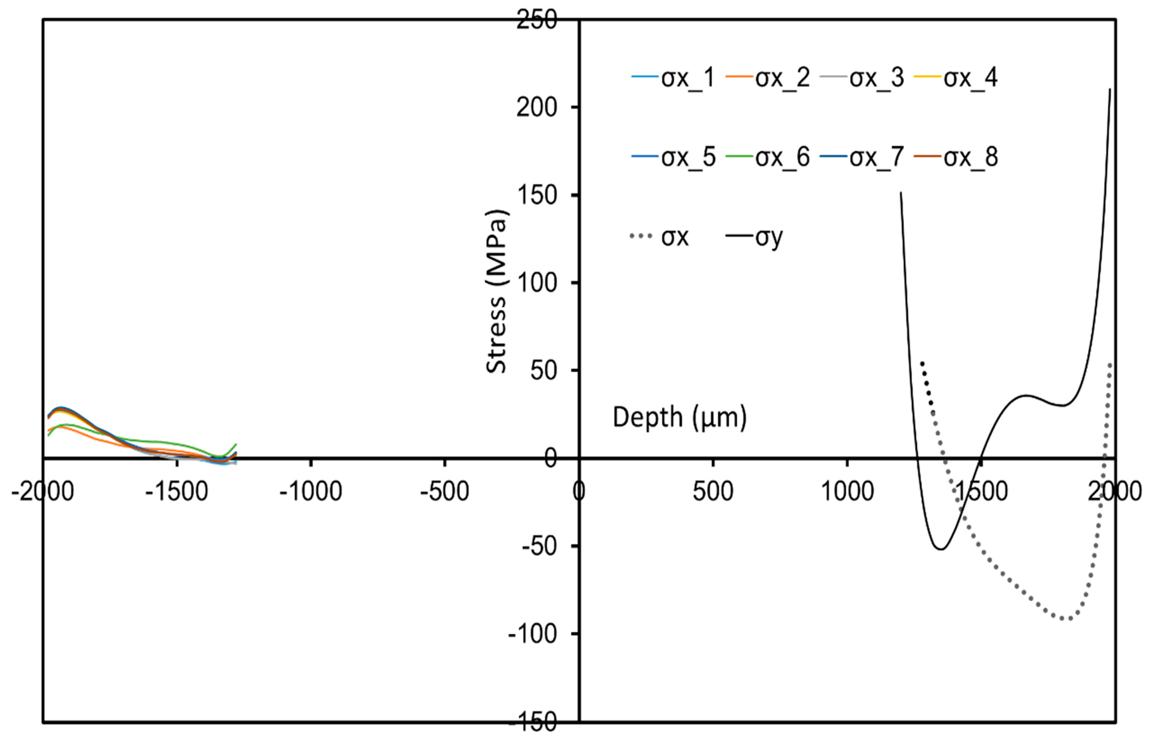
Figure 8 shows the in-depth residual stress profiles on both sides of the hybrid component, i.e., the sides of the CFRP and the metal obtained separately, for providing an overview of the stress values and distribution in the whole component. Certainly, the residual stress values and distributions are controlled by many parameters, such as process parameters (temperature and pressure) and mechanical and thermal properties of the materials. In the present work, the thickness of the CFRP and the steel is around 2 mm. However, here the HDM is only able to provide reliable results within the range of 10 to 800 μm from the sample surface according to ASTM–E837 [11] as a hole with a diameter of 2 mm is considered. In consequence, the interface between the CFRP and the metal cannot be reached. For further analysis, techniques such as synchrotron diffraction could be used at least for characterization of stresses in the entire metal part; however, such analysis is out of the scope of the present study. In Figure 8, it is clearly revealed that the residual stresses in the CFRP are much smaller than in the metal. A similar observation was also reported in [24,25] through multiscale numerical simulations [26]. This finding can be mainly explained by three reasons: (i) Young’s modulus of the resin/matrix in the CFRP is much lower as compared to steel; (ii) the thermal expansion coefficient of steel is higher than in case of the CFRP; (iii) minor residual stresses could have been induced already upon fabrication of the steel prior to hybridization (c.f. Figure 9e,f). The role of the Young’s modulus and the thermal expansion coefficient in determining residual stresses in composites and laminates can be well explained by using the classical laminate theory (CLT) combined with the formation mechanism of residual stresses in the manufacturing process [
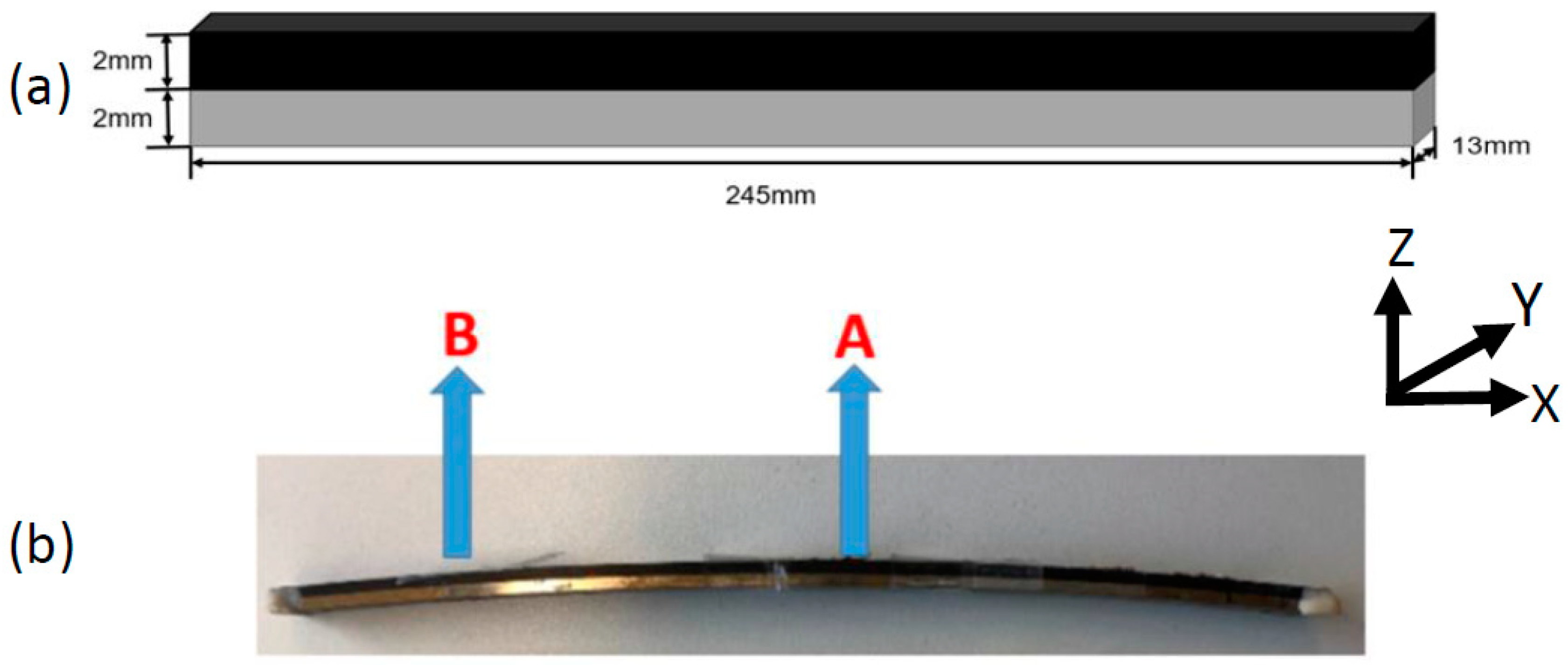
27]. The process-induced residual stresses result in bending of the hybrid sample, as shown in Figure 5b, and the curvature can be used to roughly quantify the level of residual stresses. Details on the distribution of residual stresses on the side of the CFRP and the metal, respectively, will be shown in the following part. In the present work, the degree of curvature is thought to not affect the attachment of the strain gauge on the surface of the sample and the results obtained by the HDM in general. However, future work has to be conducted to further substantiate this assumption. In the case of all results, the direction X corresponds to the fiber direction and the direction Y is transverse to the fiber (see 
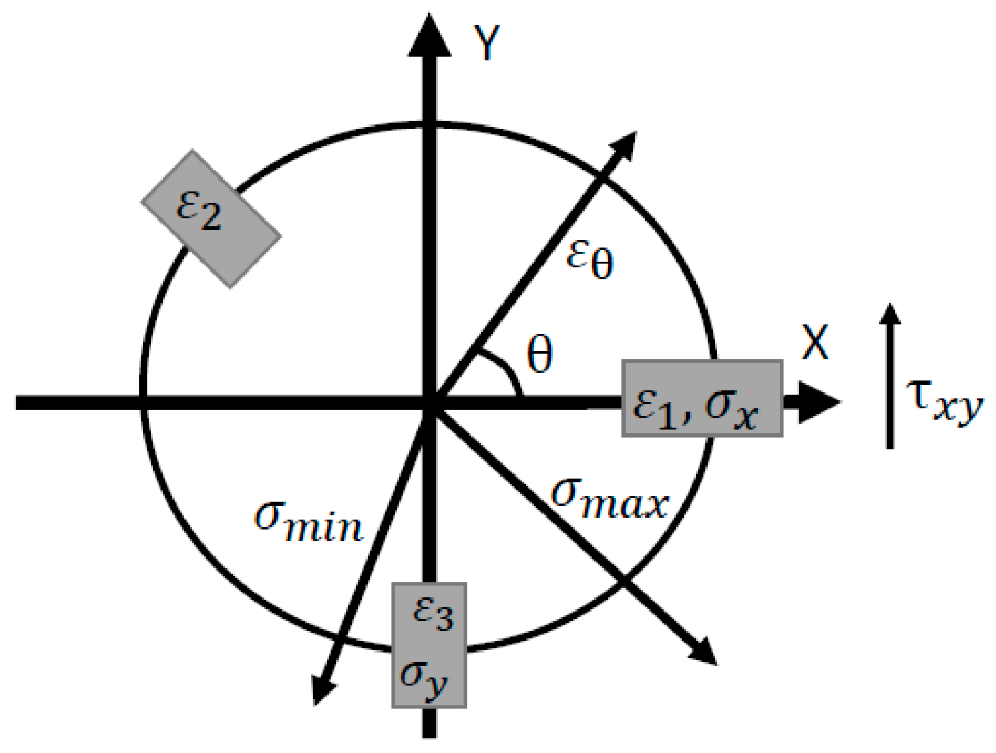
Figure 2). This definition of direction holds true not only for the CFRP but also for the metal.
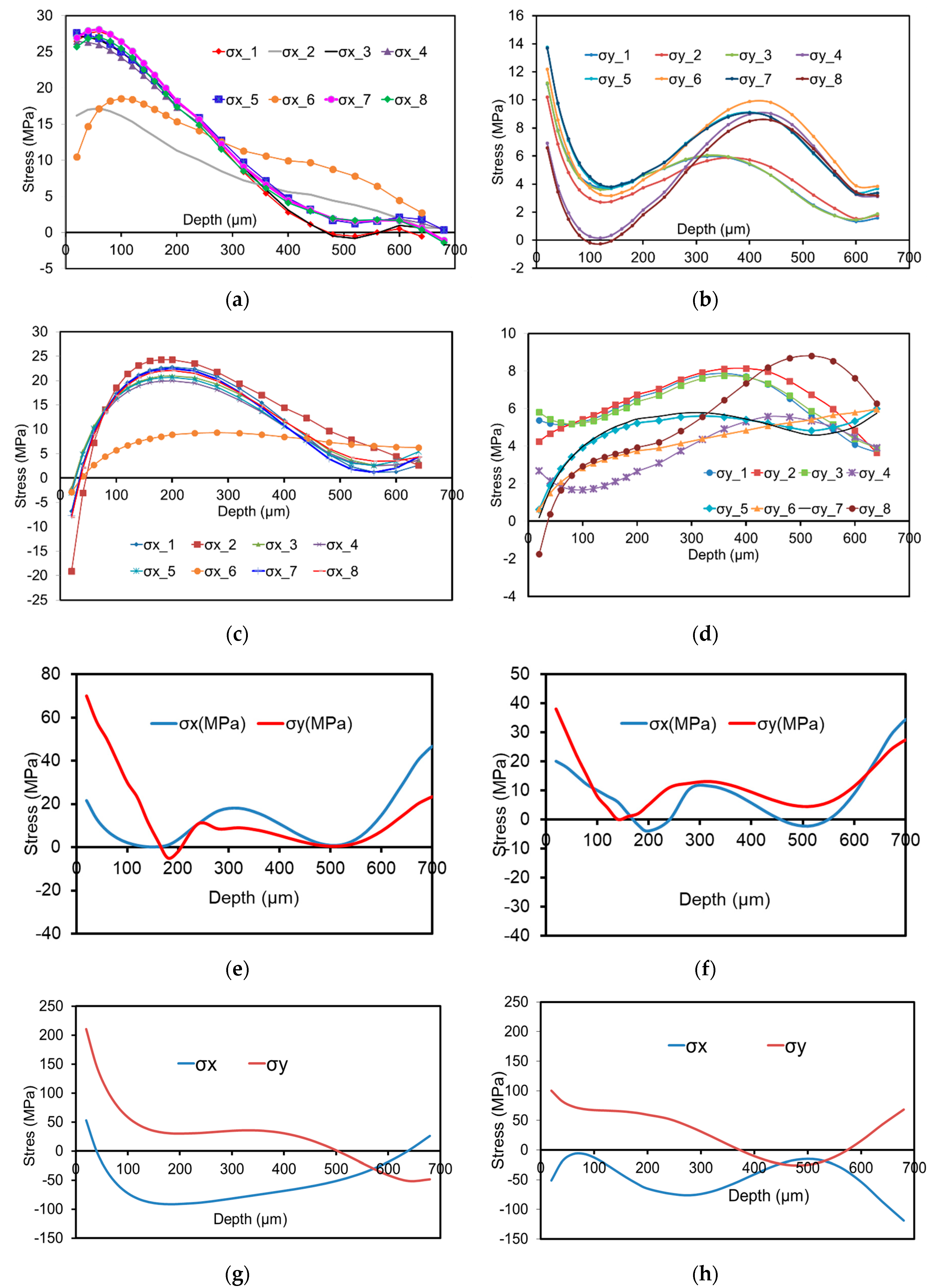
Figure 9a shows all experimentally determined residual stresses σx based on the eight different combinations (cf. Figure 2) of the measured strain at the center (A point) on the CFRP side of the bent hybrid component as defined in Figure 5b. In Figure 9a, except for the combinations of 2 and 6, the residual stresses σx of most combinations show very similar results. Characteristic are tensile stresses of around 25 MPa close to the surface, while the stress values decrease as the depth increases. The reason why the combinations of 2 and 6 show different results is the lack of strain information alongside the fiber direction (in both cases signals from strain gauges 1 and 5 are not considered). Deeper in the material, residual stresses decrease and start to diverge strongly (from a surface distance of about 0.6 mm, not shown for the sake of clarity), as the surface strain response becomes insensitive to the effects of residual stresses existing at increasing distances from the measurement surface. Figure 9b shows the results of σy at the center point A on the CFRP side, where the eight combinations of the measured strain are used to evaluate the residual stress. Here it can be seen that the results of all combinations point out tensile stresses. These tensile stresses increase to a maximum at a depth of 400 µm and at the same time are significantly smaller than σx, which is in accordance with the observation shown in Figure 7a, i.e., the released strains in longitudinal direction are much higher than other directions. It can be seen from Figure 9 that the stress profiles as a function of depth are smooth, implying the stability of the measurement. Figure 9c shows the measured residual stress σx at the side point B on the CFRP side as defined in Figure 5b. From Figure 9c, it can be deduced that the residual stresses from the surface to the depth of 50 µm are compressive stresses. The compressive stresses convert to tensile stresses at the depth of 50 µm. Afterwards, they increase to maximum values at a depth of 180 µm and then decrease. This observation can be explained by the constraints imposed by the metal part and related boundary effects. The values obtained from all combinations of the strain gauges are very similar, except of the combination of 6. Again, this can be assigned to the fact that the fiber information is not considered in this combination. The measured residual stresses σy based on the eight combinations at the side point B on the CFRP side are given in Figure 9d. Prevailing stress values σy of all combinations reveal tensile stresses with the maximum values of about 8 MPa at a depth of 400 µm, clearly being significantly smaller as compared to σx at this point.
In Figure 9e, the experimentally determined residual stresses σx and σy (using a standard strain gauge with three grids) at the center point A on the metal sample, which is not bonded with CFRP, are shown. It can be seen that σx resembles a tensile stress with a maximum value of about 20 MPa close to sample surface eventually decreasing as the depth increases. σy is characterized by tensile stresses with a maximum value of about 70 MPa close to surface. This value also decreases as the depth increases. Figure 9f shows the experimentally determined residual stresses σx and σy using a standard strain gauge with three grids at the side point B on the metal sample without hybridization. Figure 9g shows the experimentally determined residual stresses σx and σy using a standard strain gauge with three grids at the center point A on the metal side after hybridization. It can be seen that σy is characterized by tensile stresses with a maximum value of about 210 MPa close to surface. Stresses decrease to zero at the depth of 500 µm and then convert into compressive residual stresses as the depth increases. In terms of σx, in a depth ranging from 50 to 600 µm compressive stresses are revealed being characterized by a maximum value of −95 MPa at the depth of 180 µm. The stresses σx and σy on the side point B at the metal side after hybridization are shown in Figure 9h. It can be seen that the values are smaller as compared to the center point; however, their characteristic courses are somehow similar. In addition, it can be seen that the residual stresses in the steel after hybridization are larger than within the steel sample before hybridization due to the formed residual stress related to the hybridization process upon cooling. The reasons why the residual stresses in the metal part are much larger than in the CFRP already have been detailed before.
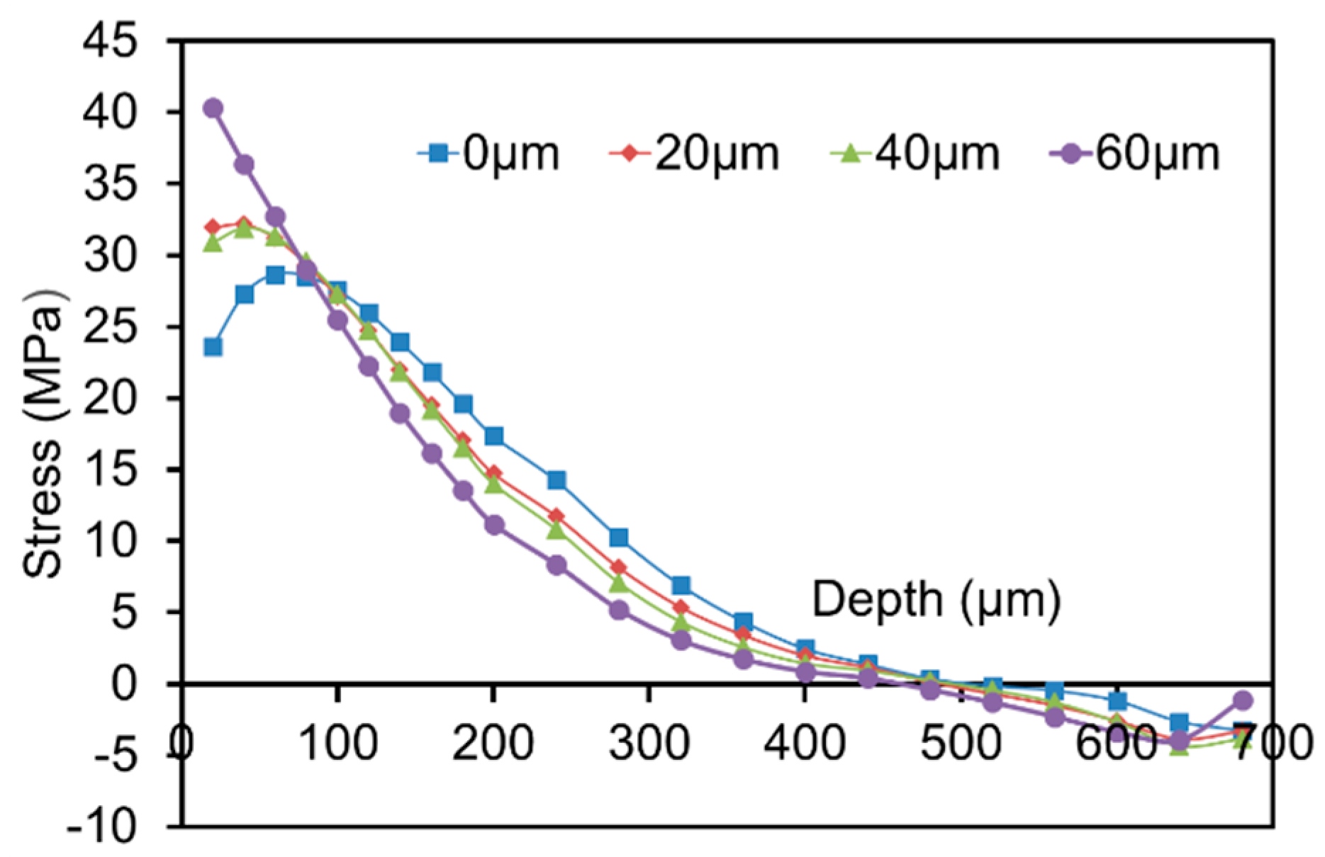
For investigating the consequences of a non-exact depth setting on the resulting residual stresses, the effect of different deviations from the ideal depth position was simulated in the procedure of evaluating the residual stresses. A key step is to precisely define the setting of the so-called zero depth, namely the surface of the sample. The ideal zero depth setting in this study was defined as follows: the removal of the coating, the foil of the strain gauge and the adhesives by successively drilling in steps of about 5–10 μm was used as a trigger signal. After each drilling, it was carefully checked whether the cutter came into contact with the surface of the sample through a camera. In Figure 10, the label (0 μm) indicates the ideal zero depth setting. This setting was employed for residual stress evaluation, while the labels (20 μm, 40 μm and 60 μm) imply that the adopted zero depth settings are 20 μm, 40 μm and 60 μm beneath the surface of the sample, respectively. From Figure 10, it can be clearly seen that the consequences of an incorrectly assumed hole depth are most pronounced in direct vicinity of the surface. Below the surface this further lead to an overestimation of the residual stress values. This effect diminishes, when the depth of the hole increases.
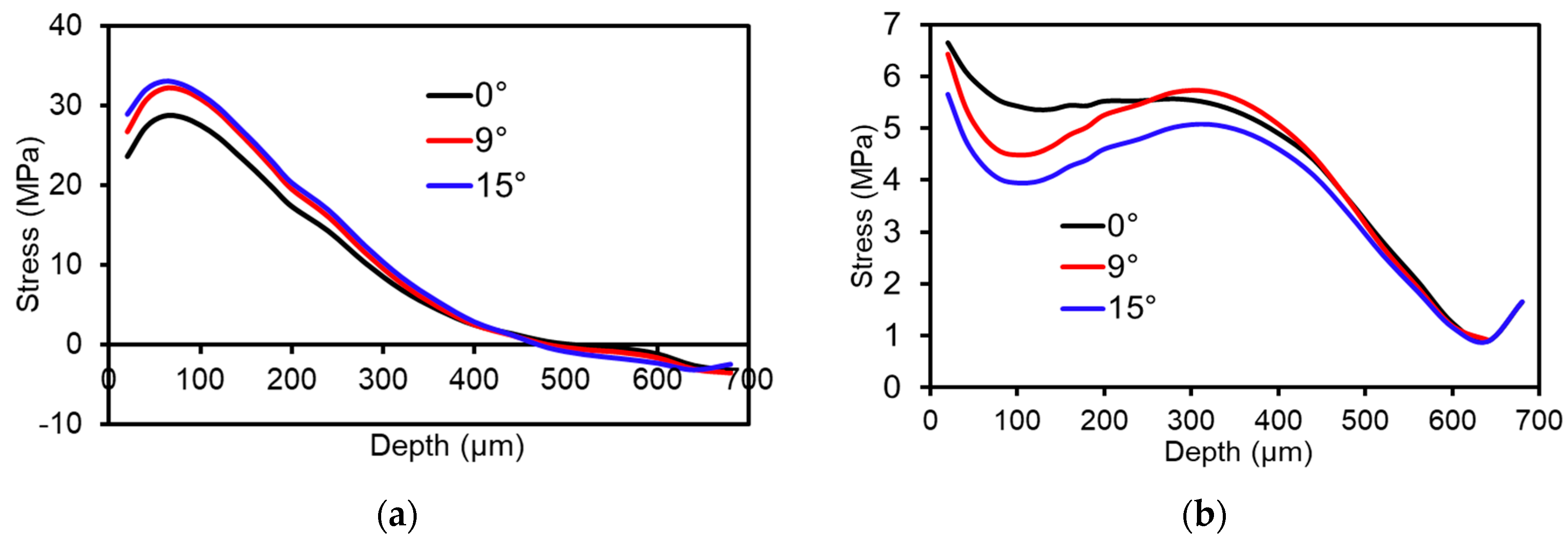
Moreover, the effect of the orientation between the actual fiber direction and the strain gauge on the resulting residual stresses has been investigated. In the evaluation formalism used, the strain gauge 1 is supposed to be aligned in fiber direction (see Figure 2a). To evaluate the impact of misalignment on the resulting residual stresses, some tests are carried out, where the strain gauge 1 is aligned with an offset angle of 0, 9 and 15 degrees to the fiber direction, respectively. Figure 11 highlights the results with respect to σx and σy. In the process of calculating the calibration coefficients through FEA (described in Section 2), the strains are numerically calculated at known positions in the model according to the position of the stain gauge attached to the surface of the sample. Then they are used to calculate the calibration coefficients with the help of the imposed stress boundary conditions through Equation (2). Clearly, when the strain gauge position is changed due to misalignment, defined by the offset angle between the fiber and the strain gauge in the present work, the calibration coefficients are required to be updated accordingly for ensuring the consistency and reliability of the residual stress evaluation. In Figure 11a, it is seen that σx is overestimated as the offset angle increases. This result can be explained as follows. As mentioned in Section 2, the stress boundary conditions in terms of σx, σy and τ xy are considered separately for determining the calibration coefficients. By imposing the stress boundary condition for σx, it is considered that the strain in X direction, i.e., in the fiber direction, is lower than in other directions due to its high stiffness. At an offset angle of 0 degree, the strain gauge 1 is perfectly aligned in fiber direction. Under the same boundary conditions, it can be deduced that the larger the offset angle is, the larger the strain is, and the smaller the corresponding calibration coefficients are. This can be regarded as a direct impact of Equation (2). The calculated calibration coefficients from FEA are employed for evaluating the residual stresses based on the strains experimentally determined by the strain gauge. Again, according to Equation (2), it is evident that non-correct calibration coefficients being too small result in larger residual stresses. Furthermore, it is observed that the effect of a misalignment is reduced as the depth of the hole increases. Figure 11b shows that σy is underestimated as the offset angle increases. Prescribing the stress boundary condition σy in the FEA, the calculated strain in the transverse direction of the fiber is larger in comparison to other directions. As the offset angle increases, it results in larger corresponding calibration coefficients and smaller residual stresses. For more detailed informations on the approach of calculating the calibration coefficients, the reader is referred to [19].

3.3. Reliability Validation of Residual Stress Measurement

The objective of this section is to validate the residual stress measurements in hybrid components using bending tests, imposing a well-defined load distribution. This procedure was already used successfully for validating the reliability of measurements in thin metal sheets [14] and in polycarbonate samples [
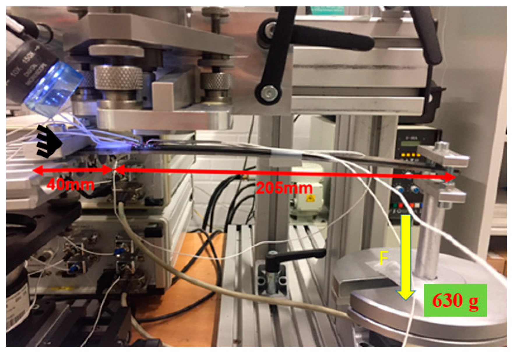
8]. In both cases, very satisfying results were found. One hybrid component with the dimension given in Figure 5 is used for validation. The validation tests are carried out on both the CFRP and the steel sides. The validation test firstly considers a residual stress measurement at a single point with the distance of 40 mm from the edge of the sample (cf. Figure 12) on the CFRP side without loading. Then, one side of the sample is clamped and the other side is loaded, as shown in Figure 12. With the given loading, the stresses imposed by the overall loading situation on the whole sample can be calculated by elastic simulation employing a FEA model, assuming that CFRP and steel are perfectly bonded. 
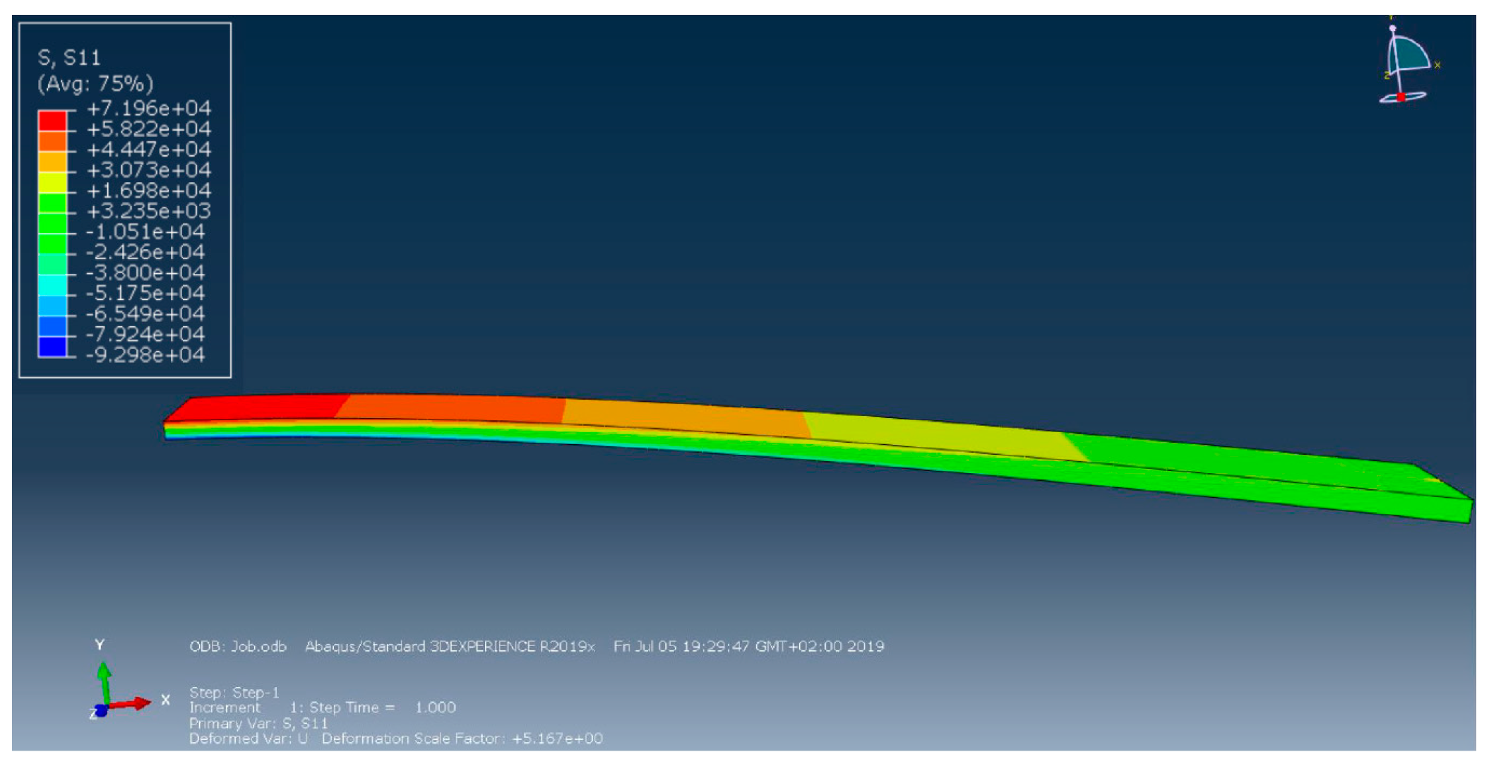
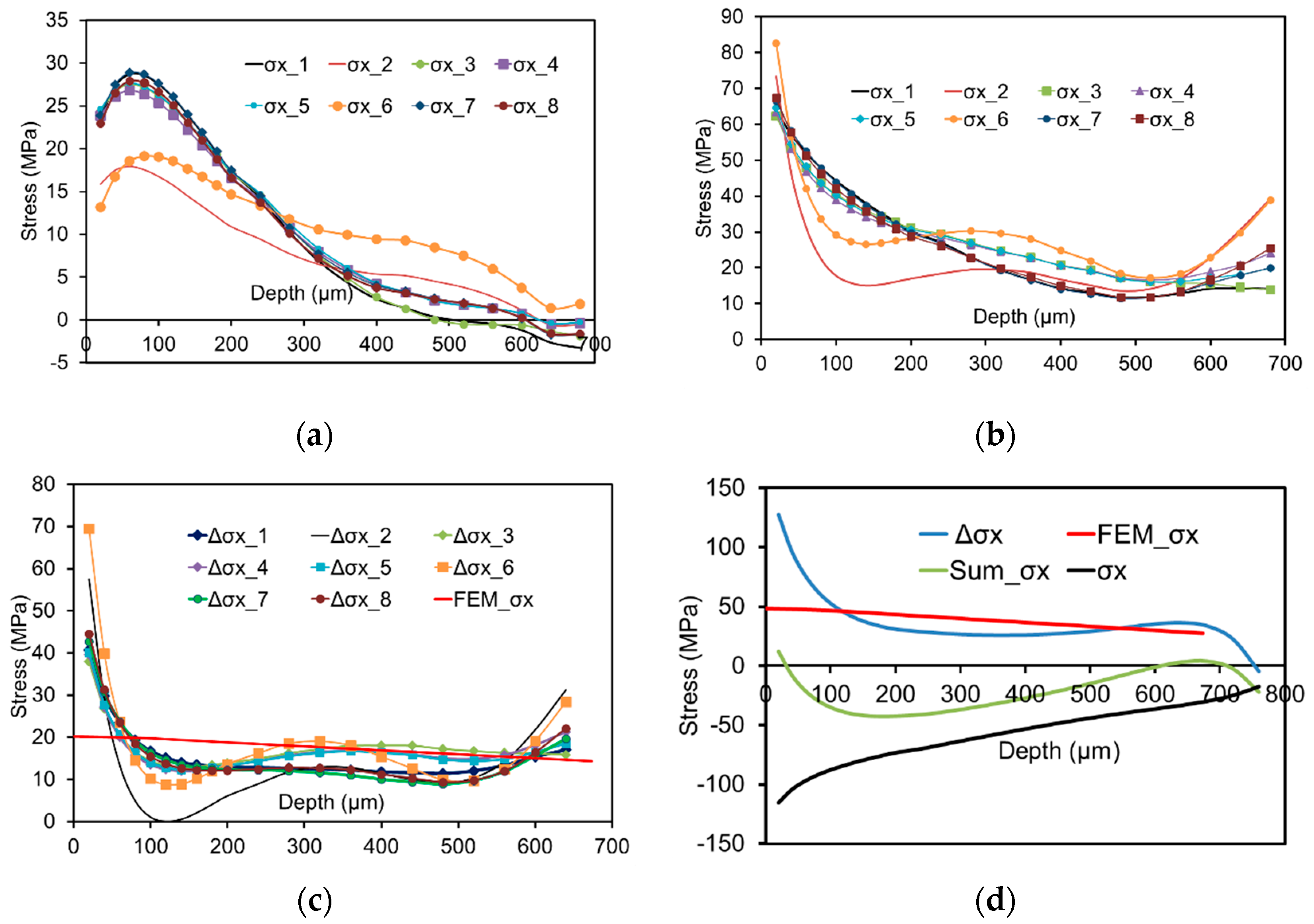
Figure 13 depicts the stress distribution in the X direction. In the present work, a weight of 630 g is fixed at one side of the sample, eventually leading to an induced surface stress of about 19 MPa at the point of drilling. Upon loading, a second hole is drilled next to the previous one (the initial hole drilled without superimposed external load). Figure 14 details the experimentally determined stresses under this loading situation, which are in turn the sum of the stresses induced by loading (Figure 14b) and the initially determined process-induced residual stresses (Figure 14a). Evaluation of data in this case is based on the assumption that without superimposed external loading, the process-induced residual stresses of two adjacent points are very similar. To avoid direct influence of the first and second hole drilled, a distance of 5 mm between both was chosen. Based on these considerations, the stress induced by loading should be equal to the difference between the initial, process induced residual stress values (without induced bending load) and the total stress values (with superimposed bending load). These values can then directly compared to the calculated values obtained through FEA (see Figure 14c). Here, the solid line corresponds to the calculated value by FEA induced by bending. It can be seen that a good agreement between the residual stress difference and the numerical value is obtained. This clearly implies that the approach introduced for the determination of residual stresses in the hybrid components considered is absolutely reliable. Similarly, the procedure has been carried out for the steel side. The comparison between the residual stress difference (with loading and without loading) and the calculated stresses through FEA is shown in Figure 14d, where Sum σx indicates the sum of the stresses induced by loading and the initially determined process-induced residual stress σx. Here, a good agreement is found as well.
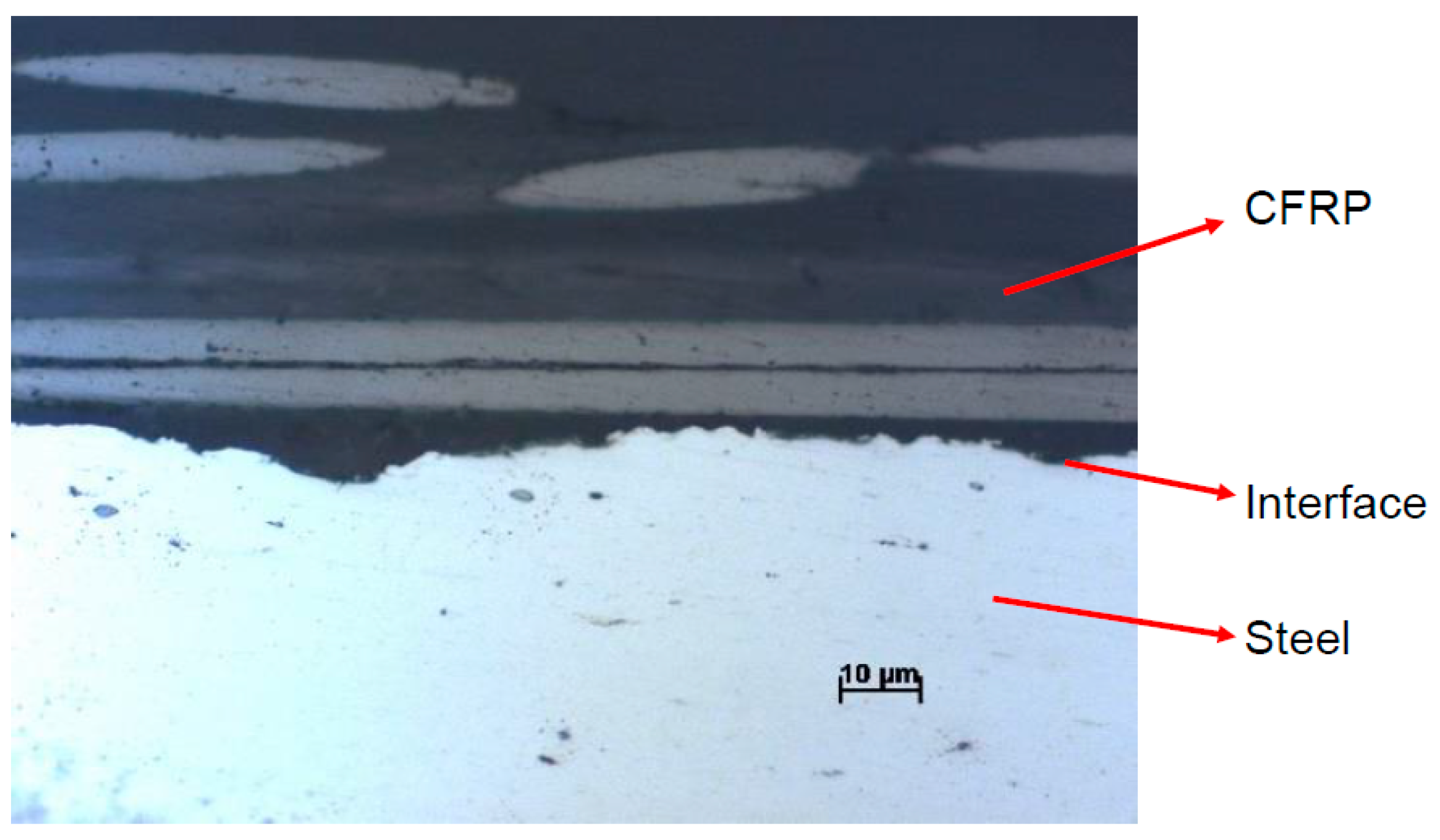
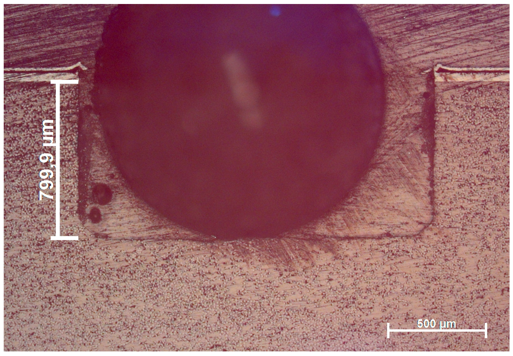
The cross-sectional microstructure of one drilled hole on the CFRP side in the hybrid composite is shown in Figure 15, where a large black hole was induced by an air bubble in the resin in the embedding process of the sample. The straight side of the hole indicates that the hole was vertically drilled. In addition, no significant damage around the hole nor cracking on the lateral face is found. These observations can ensure the reliability of the measured residual stresses given in the previous sections.
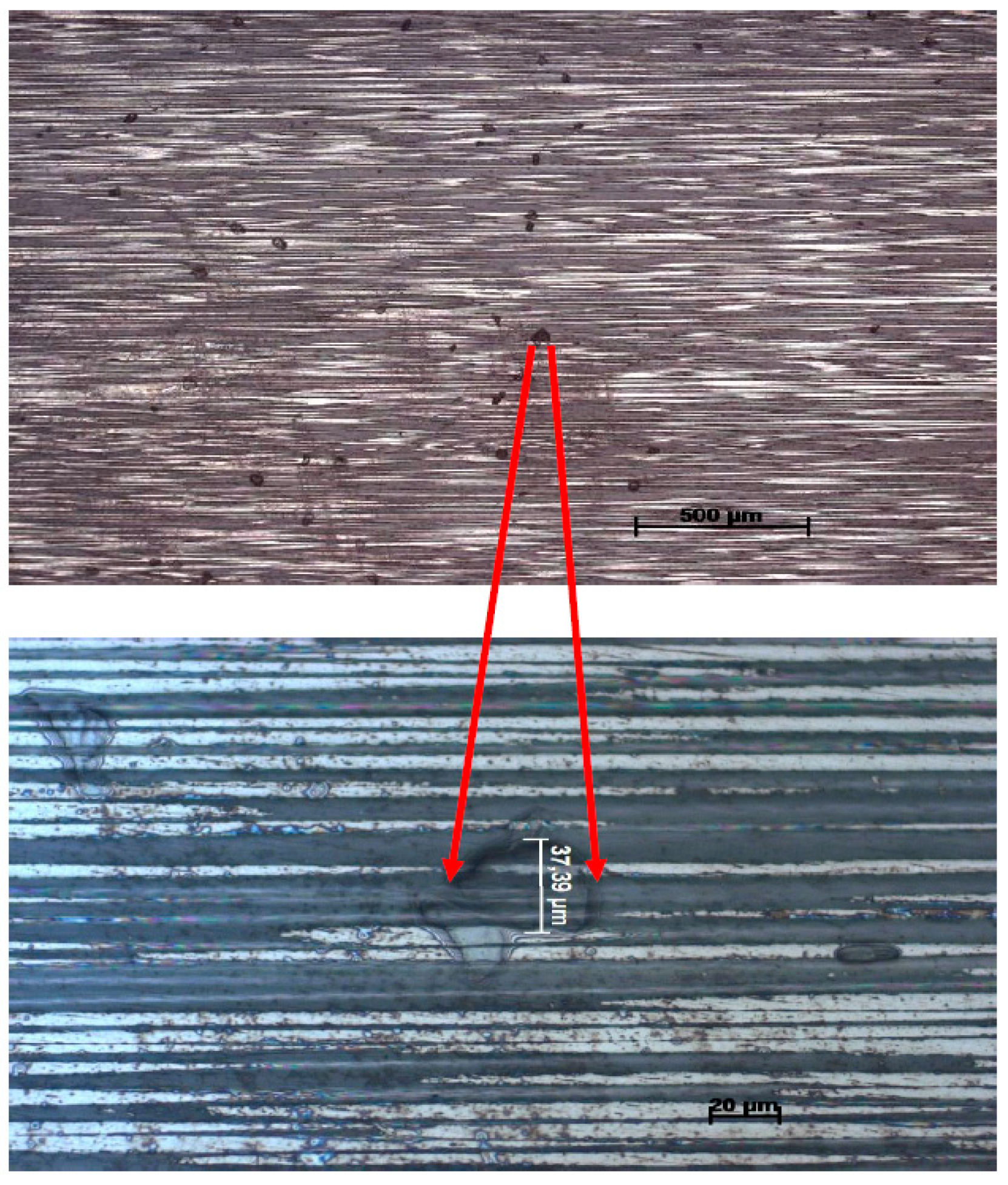
Figure 16 shows the cross-sectional microstructure of the CFRP, where defects of pore-like appearance are seen. In case such pores are present in a specific drilling increment, the strain is not relieved in the same way due to an ill-defined condition of residual stress in the vicinity of this defect. In the present work, this effect is not taken into account in the calculation of coefficients. Thus, such defects will have a detrimental effect on the reliability of the residual stress evaluation. Obviously, this effect is determined by the size and shape of the pores. This problem theoretically can be solved by obtaining the microstructural information of the sample through non-destructive techniques such as computed tomography (CT). Afterwards, relevant information on defect morphology and distribution can be used as an input for FEA for updating the calibrations coefficients. This aspect is excluded in the present work and will be the subject of a follow-up study.

4. Conclusions

In present work, hybrid components made of unidirectional carbon fiber reinforced plastics (CFRP) and steel are fabricated through an intrinsic manufacturing process, by which the bonding of CFRP and steel is achieved during the curing process of the CFRP. Due to the difference in thermal expansion coefficients of CFRP and steel, residual stresses are formed upon processing, eventually affecting the mechanical performance of the hybrid components and structures detrimentally. Within this study, the process-induced residual stresses are experimentally determined through the incremental hole drilling method (HDM). The following conclusions can be drawn from the results presented:
  • It is found that the tensile stresses are formed close to the surface of both sides, and decrease as the depth increases.
  • A misalignment of the strain gauge on the CFRP sample, eventually leading to an unexpected angle orientation between the strain gauge and the fiber, affects the resulting residual stresses. In addition, a non-exact depth setting influences the resulting residual stresses. It is found that the consequences of an incorrectly assumed hole depth are most pronounced in direct vicinity of the surface and further lead to an overestimation of the actual residual stress values below the surface. This effect diminishes when the depth of the hole increases.
  • The residual stresses in CFRP are much smaller than in the metal, which can be mainly explained by three reasons: (i) Young’s modulus of the resin/matrix in the CFRP is much lower as compared to the steel; (ii) the thermal expansion coefficient of steel is higher than in case of the CFRP; (iii) minor residual stresses could have been induced already upon fabrication of the steel prior to hybridization.
  • The applicability of the HDM for robust determination of residual stresses in CFRP/metal hybrid components has been validated by direct comparison of the experimentally determined stresses and stress values calculated by FEA-based bending simulation.
In future work, it is of highest importance to directly compare the results measured through HDM and through X-ray diffraction in direct vicinity of the boundary layer for in-depth evaluation of contributing factors on the overall residual stress state.

Author Contributions

Conceptualization, T.N. and T.T.; methodology, T.W.; software, T.W.; validation, T.W., W.Z. and S.R.T.; formal analysis, T.W.; investigation, T.W.; writing—original draft preparation, T.W.; writing—review and editing, T.W., W.Z., S.R.T., T.N. and T.T.; supervision, T.N. and T.T.; project administration, T.W., W.Z. and S.R.T.; funding acquisition, T.N. and T.T. All authors have read and agreed to the published version of the manuscript.

Funding

This research was funded by the Deutsche Forschungsgemeinschaft (DFG), project number 399304816.

Conflicts of Interest

The authors declare no conflict of interest.

References

  1. Karataş, M.A.; Gökkaya, H. A review on machinability of carbon fiber reinforced polymer (CFRP) and glass fiber reinforced polymer (GFRP) composite materials. Def. Technol. 2018, 14, 318–326. [Google Scholar] [CrossRef]
  2. Huang, Z.Q.; Sugiyama, S.; Yanagimoto, J. Adhesive–embossing hybrid joining process to fiber-reinforced thermosetting plastic and metallic thin sheets. Procedia Eng. 2014, 81, 2123–2128. [Google Scholar] [CrossRef] [Green Version]
  3. Pramanik, A.; Basak, A.K.; Dong, Y.; Sarker, P.K.; Uddin, M.S.; Littlefair, G.; Dixit, A.R.; Chattopadhyaya, S. Joining of carbon fibre reinforced polymer (CFRP) composites and aluminium alloys—A review. Compos. Part A Appl. Sci. Manuf. 2017, 101, 1–29. [Google Scholar] [CrossRef] [Green Version]
  4. Kweon, J.H.; Jung, J.W.; Kim, T.H.; Choi, J.H.; Kim, D.H. Failure of carbon composite-to-aluminum joints with combined mechanical fastening and adhesive bonding. Compos. Struct. 2006, 75, 192–198. [Google Scholar] [CrossRef]
  5. Tan, X.H.; Zhang, J.; Shan, J.G.; Yang, S.L.; Ren, J.L. Characteristics and formation mechanism of porosities in CFRP during laser joining of CFRP and steel. Compos. Part B Eng. 2015, 70, 35–43. [Google Scholar] [CrossRef]
  6. Prussak, R.; Stefaniak, D.; Hühne, C.; Sinapius, M. Evaluation of residual stress development in FRP-metal hybrids using fiber Bragg grating sensors. Prod. Eng. 2018, 12, 259–267. [Google Scholar] [CrossRef]
  7. ASTM. Standard Test Method for Determining Residual Stresses by the Hole-Drilling Strain-Gage Method; ASTM E837-13; ASTM International: West Conshohocken, PA, USA, 2013. [Google Scholar]
  8. Magnier, A.; Scholtes, B.; Niendorf, T. On the reliability of residual stress measurements in polycarbonate samples by the hole drilling method. Polym. Test. 2018, 71, 329–334. [Google Scholar] [CrossRef]
  9. Gong, X.L.; Wen, Z.M.; Su, Y.S. Experimental determination of residual stresses in composite laminates [02/θ2]s. Adv. Compos. Mater. 2014. [Google Scholar] [CrossRef]
  10. Magnier, A.; Scholtes, B.; Niendorf, T. Analysis of residual stress profiles in plastic materials using the hole drilling method—Influence factors and practical aspects. Polym. Test. 2017, 59, 29–37. [Google Scholar] [CrossRef]
  11. Magnier, A.; Wu, T.; Tinkloh, S.R.; Tröster, T.; Scholtes, B.; Niendorf, T. On the reliability of residual stress measurements in unidirectional carbon fibre reinforced epoxy composites. Polym. Test. 2020. submitted. [Google Scholar]
  12. Fontanari, V.; Frendo, F.; Bortolamedi, T.; Scardi, P. Comparison of the hole-drilling and X-ray diffraction methods for measuring the residual stresses in shot peened Al-alloys. J. Strain Anal. Eng. Des. 2005, 40, 199–209. [Google Scholar] [CrossRef]
  13. Winiarski, B.; Benedetti, M.; Fontanari, V.; Allahkarami, M.; Hanan, J.C.; Withers, P.J. High Spatial Resolution Evaluation of Residual Stresses in Shot Peened Specimens Containing Sharp and Blunt Notches by Micro-hole Drilling, Micro-slot Cutting and Micro-X-ray Diffraction Methods. Exp. Mech. 2016, 56, 1449–1463. [Google Scholar] [CrossRef] [Green Version]
  14. Magnier, A.; Zinn, W.; Niendorf, T.; Scholtes, B. Residual Stress Analysis on Thin Metal Sheets Using the Incremental Hole Drilling Method—Fundamentals and Validation. Exp. Tech. 2019, 43, 65–79. [Google Scholar] [CrossRef]
  15. Eijpe, M.P.I.M.; Powell, P.C. Residual stress evaluation in composites using a modified layer removal method. Compos. Struct. 1997, 37, 335–342. [Google Scholar] [CrossRef] [Green Version]
  16. Shokrieh, M.; Akbari, S. Simulation of slitting method for calculation of compliance functions of laminated composites. J. Compos. Mater. 2012, 46, 1101–1109. [Google Scholar] [CrossRef]
  17. Schajer, G.S.; Yang, L. Residual stress measurement in orthotropic materials using the hole drilling method. Exp. Mech. 1994, 34, 324–333. [Google Scholar] [CrossRef]
  18. Akbari, S.; Taheri-Behrooz, F.; Shokrieh, M.M. Characterization of residual stresses in a thin-walled filament wound carbon/epoxy ring using incremental hole drilling method. Compos. Sci. Technol. 2014, 94, 8–15. [Google Scholar] [CrossRef]
  19. Sicot, O.; Gong, X.L.; Cherouat, A.; Lu, J.T. Determination of Residual Stress in Composite Laminates Using the Incremental Hole-drilling Method. J. Compos. Mater. 2003, 37, 831–844. [Google Scholar] [CrossRef]
  20. Ghasemi, A.R.; Mohammadi, M.M. Residual stress measurement of fiber metal laminates using incremental hole-drilling technique in consideration of the integral method. Int. J. Mech. Sci. 2016, 114, 246–256. [Google Scholar] [CrossRef] [Green Version]
  21. Magnier, A. Residual Stress Analysis in Polymer Materials Using the Hole Drilling Method-Basic Principles and Applications. Ph.D. Thesis, University of Kassel, Kassel, Germany, 2018. [Google Scholar]
  22. Shokrieh, M.M.; Shahri, S.M.K. Modeling residual stresses in composite materials. In Residual Stresses in Composite Materials; Elsevier: Amsterdam, The Netherlands, 2014; pp. 173–193. [Google Scholar]
  23. Wübbeke, A.; Schöppner, V.; Geißler, B.; Schmidt, M.; Magnier, A.; Wu, T.; Niendorf, T.; Jakob, F.; Heim, H.P. Investigation of residual stress in polypropylene using hot plate welding. Int. Inst. Weld. 2020, in press. [Google Scholar]
  24. Nau, A.; Scholtes, B. Evaluation of the High-Speed Drilling Technique for the Incremental Hole-Drilling Method. Experimental Mechanics. Exp. Mech. 2013, 53, 531–542. [Google Scholar] [CrossRef]
  25. Gigliotti, M.; Wisnom, M.R.; Potter, K.D. Development of curvature during the cure of AS4/8552 [0/90] unsymmetric composite plates. Compos. Sci. Technol. 2003, 63, 187–197. [Google Scholar] [CrossRef]
  26. Tinkloh, S.R.; Wu, T.; Tröster, T.; Niendorf, T. A micromechanical-based finite element simulation of process-induced residual stresses in metal-CFRP-hybrid structures. Compos. Struct. 2020, 238, 111926. [Google Scholar] [CrossRef]
  27. Wu, T.; Tinkloh, S.; Tröster, T.; Zinn, W.; Niendorf, T. Residual stress measurements in GFRP/steel hybrid components. In Proceedings of the 4th International Conference Hybrid 2020: Materials and Structures, Karlsruhe, Germany, 26–27 April 2020. [Google Scholar]
Figure 1. Typical geometry of a clockwise strain gauge and the coordinate system used.
Jcs 04 00143 g001
Figure 2. (a) Special strain gauge rosette with eight grids used for strain measurement, (b) eight different combinations of strain gauge grids used for determination of residual stresses.
Jcs 04 00143 g002aJcs 04 00143 g002b
Figure 3. (a) ABAQUS finite element analysis (FEA) model used for the calculation of coefficients in the orthotropic material, (b) local cylindrical coordinate system for imposing loads at the side surface of the hole and (c) mechanical boundary conditions prescribed at the bottom surface of the sample.
Jcs 04 00143 g003
Figure 4. Experimental setup employed for manufacturing of hybrid components.
Jcs 04 00143 g004
Figure 5. (a) Dimension of the CFRP/metal hybrid component used for residual stress analysis through the hole-drilling method (HDM), (b) deformation of the CFRP/metal hybrid component induced by residual stresses (X is defined as fiber direction) (residual stresses at points A and B are to be measured and compared).
Jcs 04 00143 g005
Figure 6. Cross-sectional view highlighting the microstructure of the CFRP/steel hybrid component in direct vicinity of the interface of both materials.
Jcs 04 00143 g006
Figure 7. (a) Strain measurement on the side of the CFRP using a customized eight-grid strain gauge, (b) measured and approximated strains in the directions 1, 3, 5, 7 on the side of the CFRP and (c) measured and approximated strain on the side of the metal using a standard three-grid strain gauge (the approximated strains are highlighted by the colored lines).
Jcs 04 00143 g007
Figure 8. In-depth residual stress profile in the CFRP/metal hybrid component. Drilling has been conducted from both sides of the hybrid component separately. See text for details.
Jcs 04 00143 g008
Figure 9. Experimentally determined stresses: (a) σx at center point A on the CFRP side, (b) σy at center point A on the CFRP side, (c) σx at side point B on the CFRP side, (d) σy at side point B on the CFRP side, (e) σx and σy at center point A on the metal side without hybridization, (f) σx and σy at side point B on the metal side without hybridization, (g) σx and σy at center point A on the metal side after hybridization, and (h) σx and σy at side point B on the metal side after hybridization. Numbers provided in (a) to (d) refer to the combination of strain gauges employed for calculation (cf. Figure 2).
Jcs 04 00143 g009
Figure 10. The effect of ill-defined depth setting on the calculated residual stresses. The values given for the various curves highlight the offset considered.
Jcs 04 00143 g010
Figure 11. Effect of the orientation between the fiber and strain gauge on the residual stresses. The strain gauge has been applied with an offset angle of 0, 9 and 15 degrees, respectively. (a) σx and (b) σy, where the combination 1 of strain gauge grids in Figure 2b is employed. See text for details.
Jcs 04 00143 g011
Figure 12. Experimental set-up used for validating the reliability of residual stress measurements.
Jcs 04 00143 g012
Figure 13. Calculated σx in one bending test obtained through FEA.
Jcs 04 00143 g013
Figure 14. Experimentally determined residual stresses (a) σx on the CFRP side without external loading, (b) σx on the CFRP side with superimposed external loading, (c) reliability validation of the measured residual stress σx on the CFRP side by FEA (d) reliability validation of the measured residual stress σx on the metal side by FEA. See text for details.
Jcs 04 00143 g014
Figure 15. Cross-sectional microstructure of one drilled hole on the CFRP side in the hybrid sample (a large black hole was induced by an air bubble in the resin induced in the embedding process of the sample for analysis).
Jcs 04 00143 g015
Figure 16. Cross-sectional microstructure of the CFRP highlighting the presence of process induced porosity.
Jcs 04 00143 g016
Table 1. Relevant properties considered for the hybrid component made of a unidirectional carbon fiber-reinforced plastic (CFRP) and steel.
MaterialYoung’s Modulus (GPa)Poisson’s RatioShear Modulus (GPa)
ExEyEzνxyνxzνyzGxyGxzGyz
CFRP126.157.977.970.340.340.377.117.112.9
Steel2100.29

