Experimental Study of the Probabilistic Fatigue Residual Strength of a Carbon Fiber-Reinforced Polymer Matrix Composite


1
Department of Mechanical Engineering, North Dakota State University, Fargo, ND 58108, USA
2
Department of Engineering Mechanics, University of Nebraska-Lincoln, Lincoln, NE 58588, USA
*
Authors to whom correspondence should be addressed.
J. Compos. Sci. 2020, 4(4), 173; https://0-doi-org.brum.beds.ac.uk/10.3390/jcs4040173
Submission received: 13 October 2020
/
Revised: 14 November 2020
/
Accepted: 19 November 2020
/
Published: 21 November 2020
(This article belongs to the Special Issue Polymer Composites and Fibers)
Abstract
:Degradation of the mechanical properties of fiber-reinforced polymer matrix composites (PMCs) subjected to cyclic loading is crucial to the long-term load-carrying capability of PMC structures in practice. This paper reports the experimental study of fatigue residual tensile strength and its probabilistic distribution in a carbon fiber-reinforced PMC laminate made of unidirectional (UD) carbon-fiber/epoxy prepregs (Hexcel T2G190/F263) with the ply layup [0/±45/90]S after certain cycles of cyclic loading. The residual tensile strengths of the PMC laminates after cyclic loading of 1 (quasistatic), 2000, and 10,000 cycles were determined. Statistical analysis of the experimental data shows that the fatigue residual tensile strength of the PMC laminate follows a two-parameter Weibull distribution model with the credibility ≥ 95%. With increasing fatigue cycles, the mean value of the fatigue residual strength of the PMC specimens decreased while its deviation increased. A free-edge stress model is further adopted to explain the fatigue failure initiation of the composite laminate. The present experimental study is valuable for understanding the fatigue durability of PMC laminates as well as reliable design and performance prediction of composite structures.
1. Introduction
Fiber-reinforced polymer matrix composites (PMCs) made of high modulus microfibers (e.g., carbon, glass, boron, natural plant fibers, etc.) in compliant polymeric resins represent a large class of manmade lightweight structural materials that have been finding rapidly expanding applications in aerospace, aeronautical and ground vehicles, sports utilities, gas and liquid pipeline transportation, offshore and marine construction, and civil infrastructure, among others [1,2,3,4,5,6,7,8,9,10,11]. Such broad applications are resulting mainly from the unique properties of PMCs including their high specific stiffness and strength, excellent fatigue tolerance and immunity to corrosion, amicable manufacturability, etc., [1,2,3,5]. As microstructures, PMCs are highly heterogeneous materials, and when subjected to external loading, high stress inhomogeneities and stress singularities exist in PMCs, which result in their progressive damage [12]. Typically, the evolution of structural damage in PMCs includes microcrack nucleation, growth and propagation in resins, delamination between neighboring laminas, fiber debonding, fiber break, and, finally, catastrophic failure of the PMC specimens or structures [12,13,14]. Obviously, the evolution of this microscale to macroscale damage in PMCs is thermodynamically irreversible, which gradually degrades the load-carrying capacity of the PMCs until catastrophic failure happens. With the ever expanding applications of PMCs in transportation and other engineering sectors in recent years, the long-term mechanical and other physical behaviors of PMCs subjected to cyclic loading have become one of the important research topics in composite design, manufacturing, testing, and applications [15,16,17]. To date, substantial experimental and theoretical investigations have been conducted to understand the fatigue behaviors of composite materials subjected to cyclic loadings. To mention a few, Diao et al. [18,19,20] studied the fatigue response of carbon-fiber/PEEK composite laminates and formulated a statistical physics-based fatigue model to interpret their observations. Wu [21] conducted the thermomechanical fatigue tests of advanced composite laminates made of unidirectional (UD) carbon-fiber/epoxy prepregs and detected two opposite thermal effects in the mechanical behavior of such composites, i.e., thermally triggered fatigue failure and resin toughening, which can be related to the rate effect of PMC fracture [22]. Dzenis et al. [23,24,25] performed the fatigue tests on a UD carbon-fiber/epoxy composite laminate and studied the cycle-based damage accumulation in the composite laminates by using an acoustic emission (AE) technique. In the specific case of adhesively bonded composite joints, they further identified the fatigue fracture modes by comparing the collected AE signals with those obtained in pure mode fatigue fracture tests. Rudov-Clark and Mouritz [26] conducted the tension–tension fatigue tests of a three-dimensional (3D) orthogonal woven composite and found that the fatigue response of such a 3D woven composite was more complicated than that of composite laminates due to its 3D woven fiber architecture and related inhomogeneous stress and strain states. In order to understand the stiffness degradation of UD fiber-reinforced composite laminates subjected to cyclic loads, Cista et al. [27] formulated a progressive damage model based on the concept of fiber fragmentation, in which fatigue damage was simplified as cumulative fiber breakage. Moreover, significant experimental studies have also been performed to explore the fatigue fracture of fiber-reinforced composite laminates with precracks (delamination) and notches [28,29,30,31,32,33,34], which were focused mainly on the pure or mixed mode fatigue crack growth rate with respect to the mean value and amplitude of the stress intensity factor (SIF) and frequency of the applied cyclic loadings. So far, standard test methods for pure and mixed mode fatigue tests of fiber-reinforced composite laminates have been formulated [35,36]. Detailed reviews on recent experimental research of fatigue delamination of fiber-reinforced composite laminates and related fatigue damage modeling are available in the literature [37,38,39,40].
In addition, it is critically important to understand and predict the reliable lifetime and progressive evolution of the mechanical properties of composite materials subjected to cyclic loading. In the past three decades, substantial experimental and theoretical studies have been devoted to determining and modeling the evolution of the residual strength of composite laminates in the literature [41,42,43,44,45,46,47,48,49,50,51,52,53,54,55]. To mention a few, in an earlier study of the fatigue residual strength of composite materials, Yang [41] proposed a phenomenological fatigue residual strength model with a linear strength degradation with respect to the fatigue cycle, which was largely validated by the detailed fatigue tests of a quasi-isotropic graphite/epoxy composite laminate with a layup of [0/45/90/-452/90/45/0]2 with fitted model parameters. Hashin [42] utilized cumulative damage theory to formulate a residual life and residual strength model based on the master SN curves, which can deal with multistage loading cases. Diao et al. [44] formulated a stochastic model of the residual strength and fatigue life of composite laminates to take into account the governing damage modes in the laminate such as matrix cracking and delamination. This model was validated by their fatigue test data of a UD glass-fiber/epoxy laminate. Paepegem and Degrieck [46] utilized the concept of damage growth rate to formulate a kinetic fatigue damage model to predict the residual strength of composite laminates. Philippidis and Passipoularidis [48] performed the comparative studies and review of several existing residual strength models and their experimental validation in the literature. They concluded that the use of complicated phenomenological models required large experimental data sets for implementation and did not necessarily pay back in terms of accurate predictions and that simple models requiring limited experimental efforts could be preferable. Mejri et al. [51] conducted the bending fatigue tests of natural fiber-reinforced composites subjected to cyclic loading of constant strain level. They defined the residual fatigue strength as the maximum flexural stress of the sample, which progressively degraded with cycles as the result of cumulative damage in the material (stiffness degradation). Their results showed that at varying strain levels of the composite samples, the cumulative probability of failure of the samples followed a two-parameter Weibull distribution with respect to the fatigue cycle. Based on selected experimental data in the literature, D’Amore et al. [52,53] conducted the comparative study of several phenomenological residual strength models for composite materials subjected to constant stress levels with the purpose of model selection for experimental data reduction. Recently, Ganesan and Joanna [54] conducted the tension–tension fatigue test of a carbon-fiber/epoxy composite laminate at varying stress levels of 70, 80, and 90% of the ultimate tensile strength, to determine the evolution of fatigue residual strength, which can fit well into the residual strength wear-out model with power-law deterioration of the material strength proposed by D’Amore [55]. In these above works, the fatigue residual strength of the composite materials was mainly treated as a function with respect to the fatigue cycle and the effect of its randomness at a given fatigue cycle was not considered.
More recently, with the concept of improving the delamination toughness of fiber-reinforced composite laminates by involving ultrathin nonwoven polymeric or carbon nanofibers at ply interfaces [56,57,58,59,60,61,62,63,64,65,66,67,68], researchers have also examined the toughening effects of continuous nanofibers on the fatigue behaviors of composite laminates [14,59,60,69,70,71]. These experimental investigations have shown that a small quantity of continuous nanofibers, typically produced by means of the low-cost, top-down electrospinning technique [72,73,74,75,76,77,78,79,80,81,82,83,84,85,86,87,88,89,90,91], placed at laminate interfaces can significantly enhance the fatigue durability via enhancing the interlaminar fracture toughness and suppressing the stress singularity at the crack tips, which opens a new field of developing novel multiscale fiber-reinforced composite materials with greatly enhanced delamination toughness and fatigue durability [57,63,90]. In particular, such interface toughening strategy can effectively suppress free-edge delamination in angle-ply composite laminates. As a matter of fact, coupling of in-plane and out-of-plane deformations in angle-ply composite laminates commonly leads to singular free-edge stresses in the laminates when subjected to in-plane loading such as in-plane tension–tension cyclic loading [92,93]. Such singular free-edge stresses are responsible for the premature failure and initiation of fatigue cracks at the free edges of composite laminates. In fact, in-plane loading even with very low amplitude can potentially result in the free-edge delamination in composite laminates due to the singular nature of free-edge stresses, which further grow under cyclic fatigue loading until the catastrophic failure of the laminates. Due to the importance of free-edge stresses in composite laminates, several successful methods have been formulated for computing the free-edge stresses and layup sequence design of composite laminates in the past three decades, which were based largely on finite element methods (FEMs) and semianalytic methods [92,93,94,95,96,97,98,99,100,101,102,103,104]. A detailed review on advances in free-edge stress simulations in the last three decades was made by Mittelstedt and Becker [105]. Among others, Wu [14,60,106] refined and extended Yin’s stress-functional variation method [94,95] and enabled this high-efficiency method capable of accurately determining the free-edge stresses of angle-ply composite laminates made of up to 70 plies, in which the singular stress field way a ply thickness from the free edges of a composite laminate was very close to that predicted by detailed finite element analysis (FEA). Wu and his coworkers further extended this method to formulate the general stress-function variational methods for free-edge stress analysis of bonded joints [107,108], adhesively bonded joints [109], and adhesively bonded composite joints [110], and cracked surface coatings [111]. These high-efficiency semianalytic methods provide powerful tools for understanding the failure initiation and growth in composite laminates subjected to quasistatic or cyclic in-plane, bending, or twisting loads.
On the other hand, fatigue tests of composite materials to date have been focused on stiffness degradation and lifetime of various uniaxial tensile or bending composite specimens. Relatively fewer fatigue tests were performed to symmetrically study the strength degradation of composite laminates with respect to the fatigue cycle though the strength is the most important parameter to characterize the load-carrying capacity of a composite material [112]. Different from the stiffness measurement that can be repeatedly recorded from a fatigue test to track the stiffness degradation with increasing fatigue cycle, characterization of the tensile strength of a composite laminate is a one-time failure test, and each specimen can only be used to generate one sampling data point. So far, the literature database of fatigue residual strength of composite laminates after fatigue loading of certain cycles is still limited. Therefore, in this work we conducted the experimental study to determine the fatigue residual tensile strength of an angle-ply carbon-fiber/epoxy composite laminate made of UD carbon-fiber/epoxy prepregs (Hexcel T2G190/F263) with the ply layup [0/±45/90]S after fatigue loading of certain cycles. The quasistatic tensile strength and the residual tensile strengths of the PMC laminate after cyclic loading of 2000 and 10,000 cycles were determined, respectively. Two-parameter Weibull model was used for statistical analysis of the experimental data to examine the variation of the model parameters with fatigue cycles. A free-edge stress model was further adopted to explain the fatigue failure initiation of the composite specimens. Finally, conclusions of the present study were drawn.
2. Experimental
2.1. Composite Laminate Processing and Specimen Preparation for Quasistatic Tension and Fatigue Tests
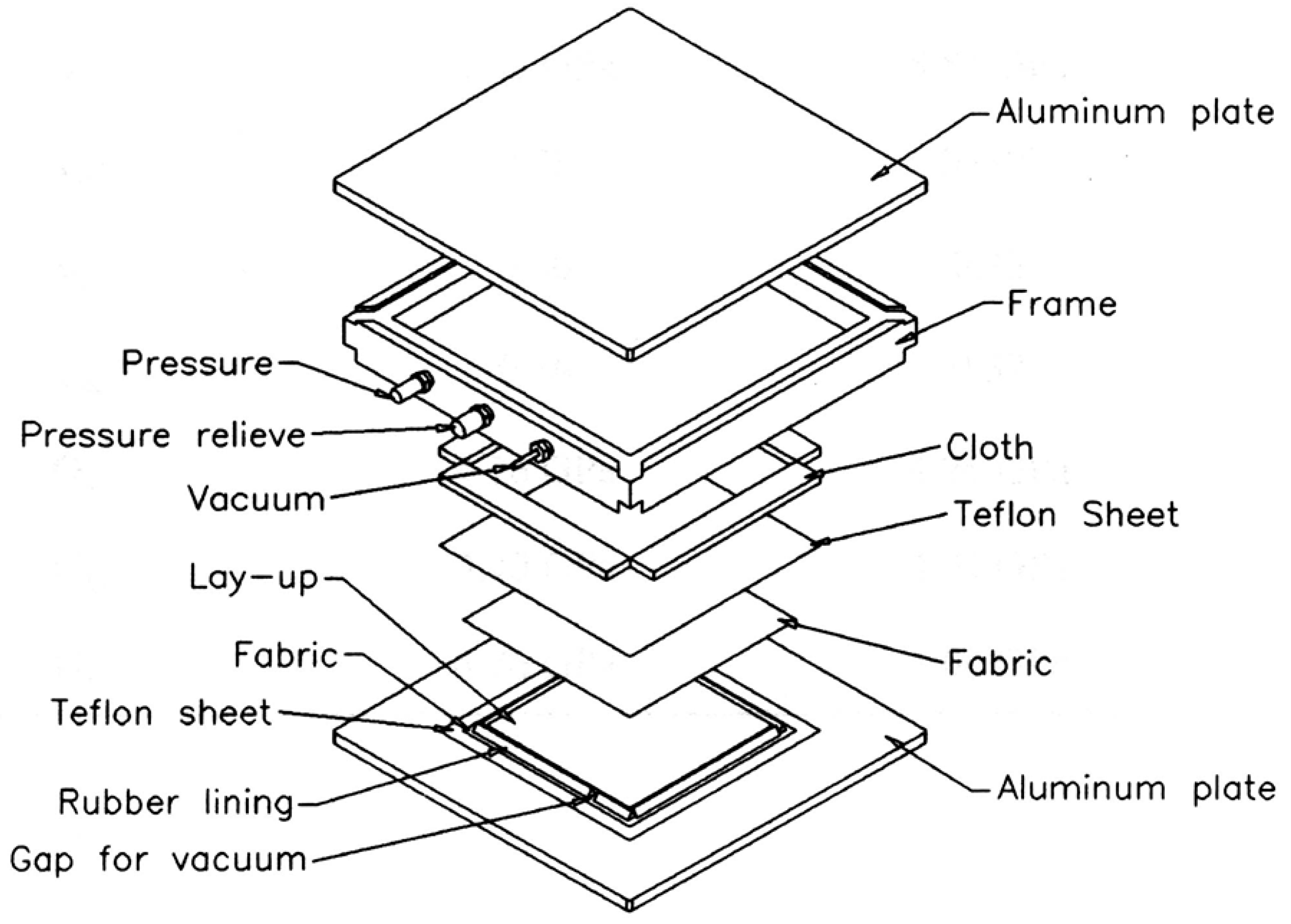
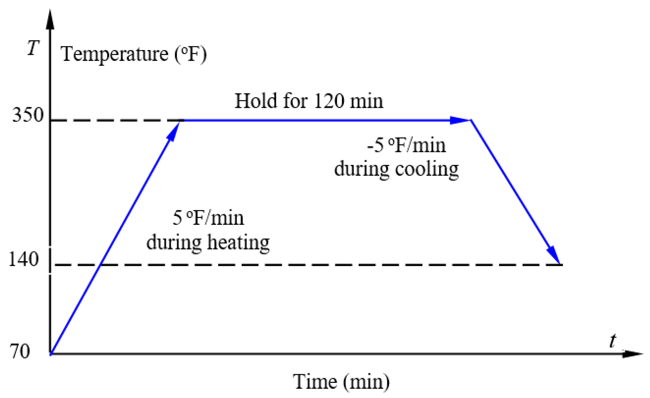
The thermosetting polymer composite laminate used for this study was made of Hexcel T2G190/F263 supplied by Hexcel Co., Stamford, CT, USA. The UD carbon-fiber/epoxy prepregs were reinforced with UD T300 carbon fibers. The in-plane mechanical properties of the resulting UD carbon-fiber/epoxy laminate are listed in Table 1 [14]. In this experimental investigation, four laminated panels with a quasi-isotropic layup of [0/±45/90]S were assembled following a hand lay-up procedure. Each laminated panel was cured within a vacuum-assisted two-chamber press-clave (as illustrated in Figure 1), which was assembled into a 15-ton hydraulic hot-press installed with an electrical heating unit (the Carve Inc., Wabash, IN, USA) under controlled temperature, pressure and vacuum environment. The manufacturer recommended curing cycle was applied as
- (1)
- 5 °F/min to 350 ± 5 °F (177 ± 3 °C);
- (2)
- 120 min at 350 ± 5 °F (177 ± 3 °C);
- (3)
- −5 °F/min to 140 ± 5 °F (± 3 °C);
- (4)
- 80 ± 5 psi (0.55 ± 0.03 MPa).
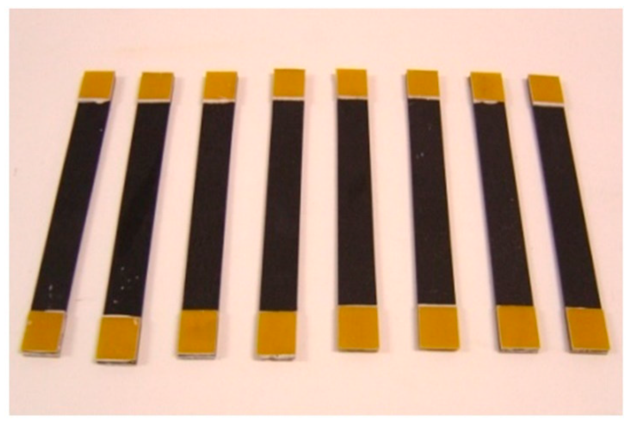
The curing temperature profile of the Hexcel T2G190/F263 prepregs is shown in Figure 2. The laminated panels after curing were tabbed using composite strips, which were cut from a commercial woven glass-fabric/epoxy composite laminate, and a Miller Stephenson two-part adhesive 907. The tabbing can prevent premature failure of the composite near the specimen grips at the two ends and ensure that the final failure happened at the middle segment of the specimens. Rectangular composite specimens were machined from the tabbed composite panels at room temperature using a high-speed diamond saw installed with a water-cooling system, as shown in Figure 3. The specimen dimensions were 135 mm in length, 15 mm in width, and 1.35 mm in thickness. All the free-edges of the composite specimens were carefully polished using fine sandpaper to avoid premature edge delamination.
2.2. Quasistatic Tension and tension–tension Fatigue Tests of the PMC Specimens
Quasistatic tension and tension–tension fatigue tests were performed on an MTS servo-hydraulic testing machine installed with an Instron data acquisition and reduction system. Quasistatic uniaxial tension tests based on ASME standard D3039/D3039M-17 [113] were utilized to determine the static ultimate tensile strength and its probabilistic distribution of the composite laminate used in this study. During the quasistatic tension tests, displacement-control method with the loading rate of 1 mm/min was specified and 27 specimens were tested.
For the tension–tension fatigue tests of the composite specimens, the ASTM standard D 3479/D3479M-19 was maintained [114]. The fatigue peak loading stress was specified as 289.85 MPa, which is close to 0.85 of the mean static tensile strength of the composite laminate that was determined from the quasistatic tension tests. Such fatigue peak loading stress does not evoke the first ply failure of the composite laminate according to the classic laminate theory (CLT, See Section 3). During the tension–tension fatigue tests, triangular loading wave was specified, the loading ratio R (=σmin/σmax) was set as 0.1, and the fatigue frequency was selected as 5 Hz. Two sets of 12 composite specimens with the dimensions and processing procedure the same as those for quasistatic tension tests were used for fatigue tests of fixed cycles of 2000 and 10,000, respectively. After each fatigue test, the quasistatic tension test was further performed to determine the residual ultimate tensile strength of the surviving specimen using a displacement-control method with the loading rate of 1 mm/min.
3. Data Reduction, Probabilistic Model Fitting, Free-Edge Stress Prediction, and Discussions
3.1. Data Reduction and Probabilistic Residual Strength Model Fitting
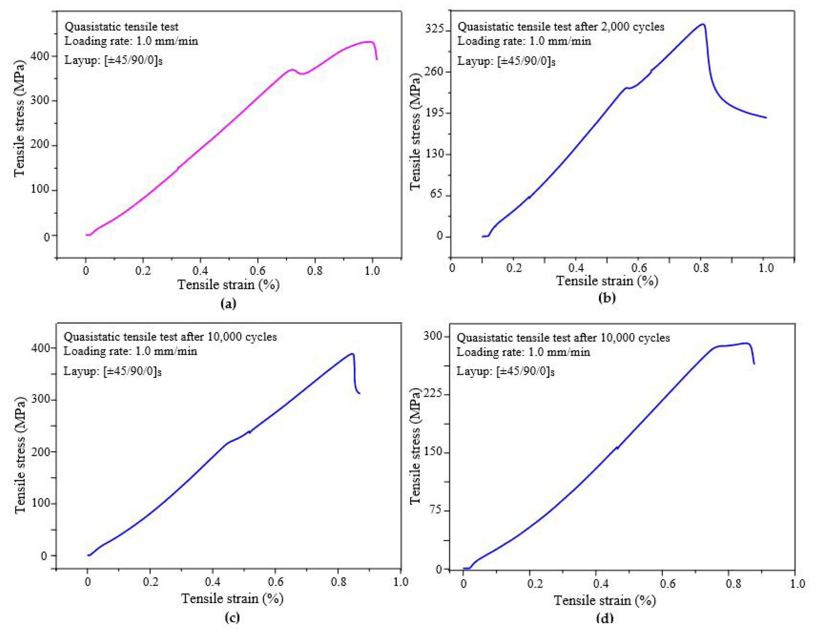
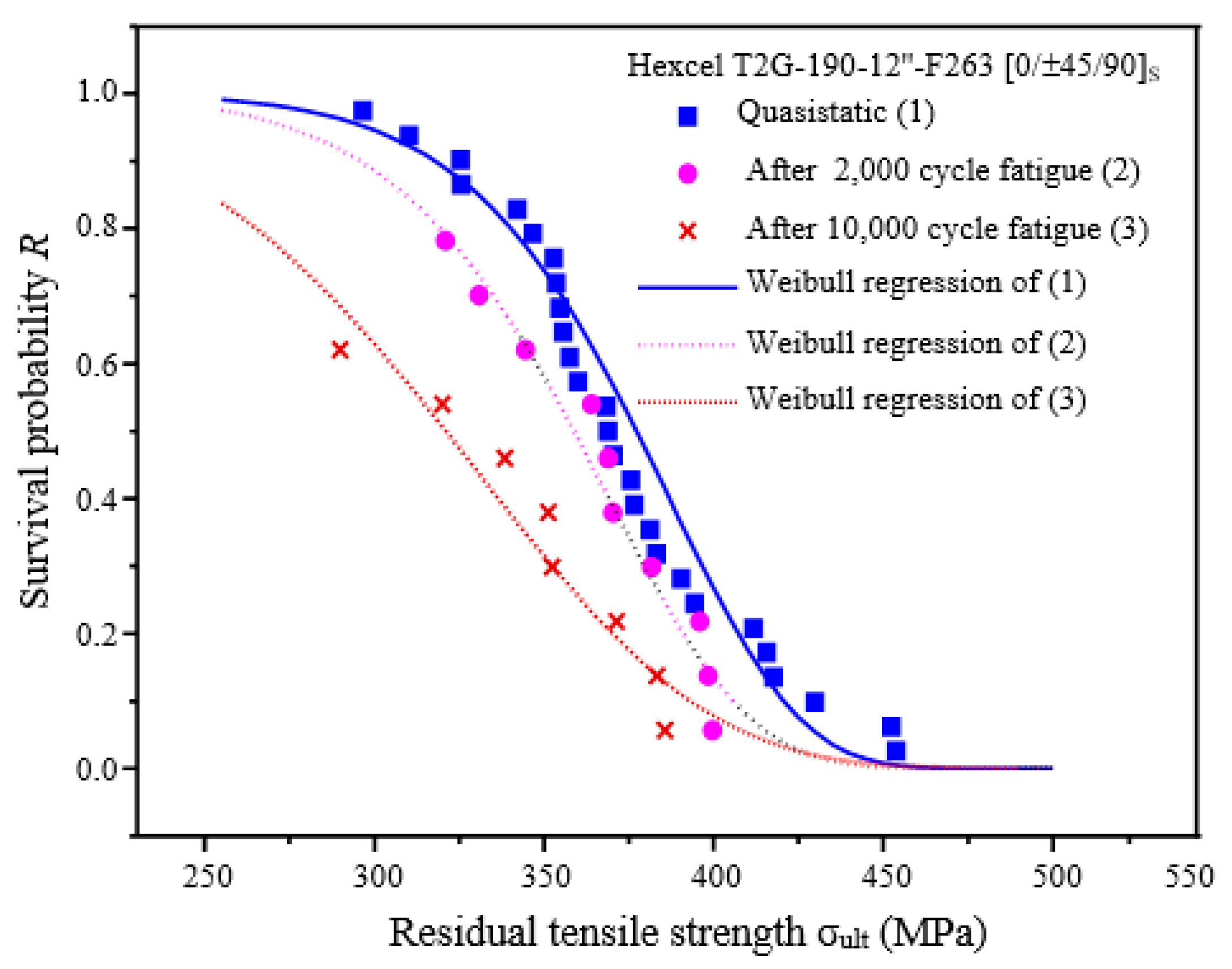
Figure 4 shows the typical quasistatic tensile stress–strain diagrams of the composite specimens without fatigue loading, after 2000-cycle fatigue loading, and after 10,000-cycle loading. It was found that the effective tensile modulus of the composite specimens slightly decreased after certain cycles of fatigue loading due to the cumulative damage. Stress drops before the final failure could be detected in each stress–strain diagram due to the progressive damage with increasing loading level. Experimental data of the quasistatic tension tests show that the tensile strength of the composite specimens has a wide range of distribution for either quasistatic loading or fatigue loading for 2000 or 10,000 cycles. As a matter of fact, for an angle-ply fiber-reinforced PMC laminate, a variety of random factors, such as fiber strength, resin strength and toughness, fiber alignment, fiber/matrix bonding strength, ply orientation, voids, etc., influence the effective mechanical properties of the laminate. Thus, with sufficient testing specimens, it is more suitable to adopt probabilistic models for data reduction of the quasistatic tensile strength and fatigue residual tensile strength of the composite laminate, which would provide more specific information to understand the statistical behavior of the material properties for reliable structural design and analysis.
Hereafter, we introduce the probabilistic models of the quasistatic and fatigue residual tensile strengths of the composite laminate for experimental data reduction. In the view of reliability theory, the survival probabilities of the quasistatic tensile failure and fatigue residual tensile failure of the composite laminate are obtained through the median rank formula [51,106,115]:
where i is the i-th specimen for a sample size of n specimens in an increasing tensile or fatigue residual tensile strength sequence. It is assumed that both the quasistatic tensile strength and the fatigue residual tensile strength of the tested composite laminate obey three two-parameter Weibull distributions with different parameters, each of which corresponds to the survival probability at tensile stress σ in a quasistatic tensile failure (either before or after fatigue loading of certain cycles) as
and the corresponding mean value of the strength is
In the above, m and σ0 are the shape and scale parameters of a two-parameter Weibull distribution, respectively, and Γ( ) is the Γ-function defined as
The two unknown parameters m and σ0 for each two-parameter Weibull model of either the quasistatic tensile strength or the fatigue residual strength after fatigue loading of certain cycles can be determined by means of the maximum-likelihood estimation method, as shown in Table 2. In each case, the two-parameter Weibull distribution of the tensile strength has an acceptable credibility R ≥ 0.95, which indicates that both the quasistatic tensile strength and the fatigue residual strength of the composite laminate obey the two-parameter Weibull distribution very well. It can be also found from Table 2 that the values of both the shape parameter m and scale parameter σ0 of the two-parameter Weibull model decrease with increasing cycle of fatigue loading.
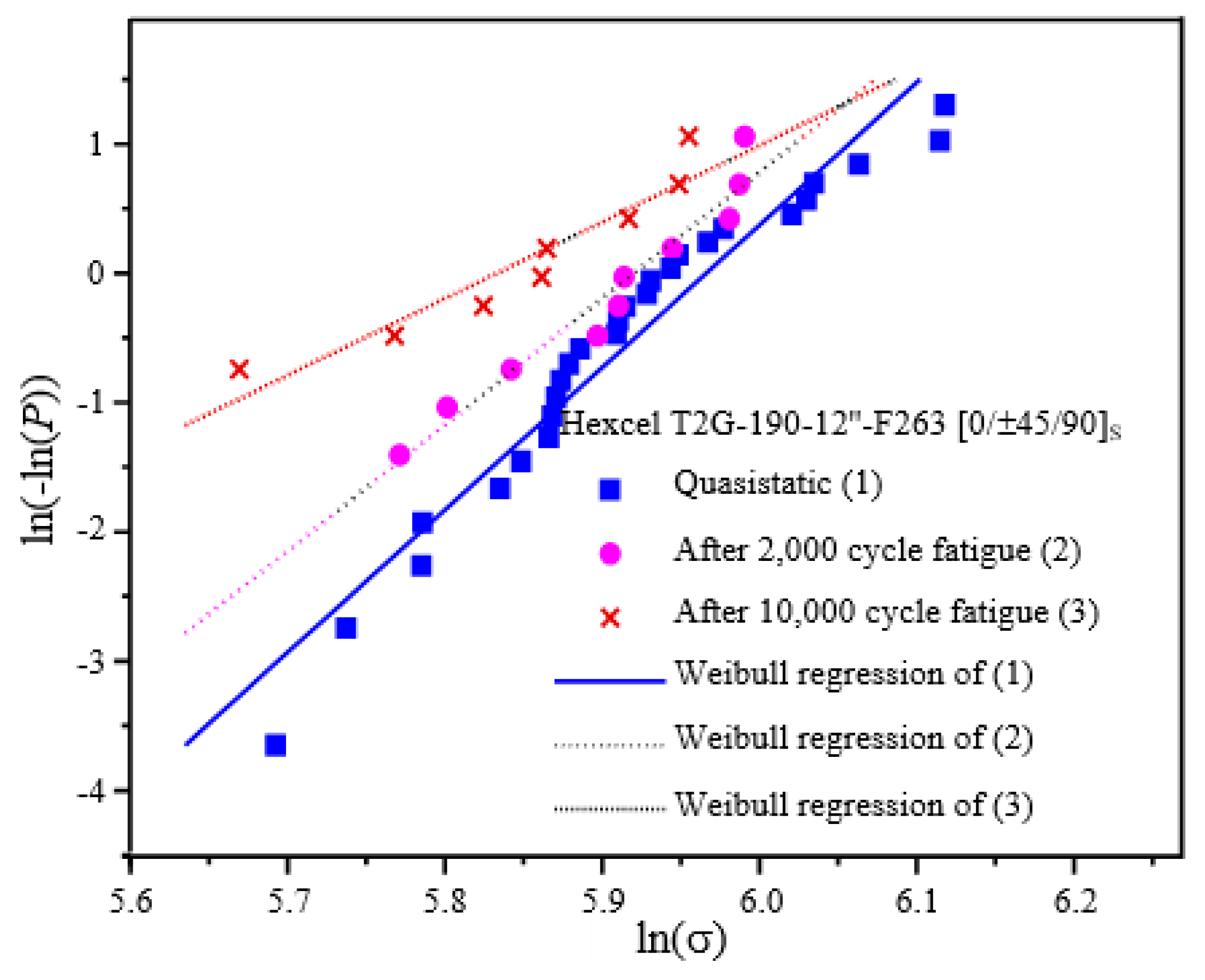
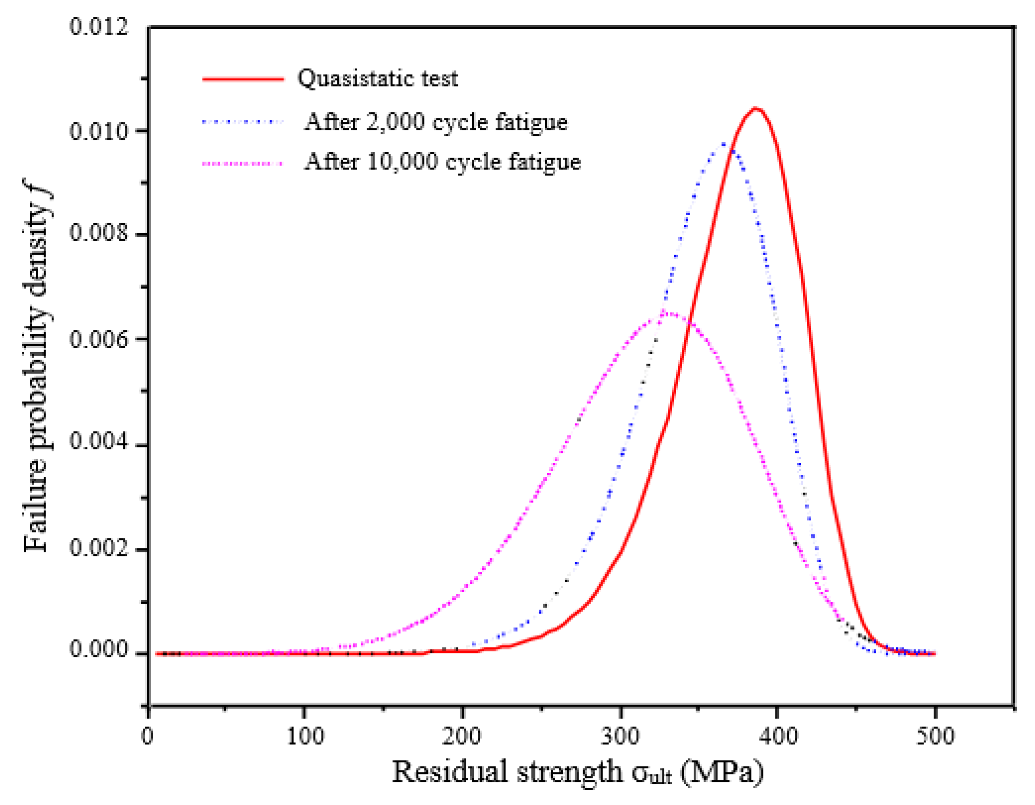
Survival probabilities of the quasistatic tensile strength and the fatigue residual strengths of the composite laminate after fatigue loading of 2000 and 10,000 cycles are plotted in symbols with significant scattering in Figure 5 and Figure 6. Correspondingly, the survival probabilities predicted by the three Weibull distribution models are plotted with curves in Figure 5 and lines in Figure 6 as well. The failure probability densities of the quasistatic ultimate tensile failure and the fatigue residual ultimate tensile failure are shown in Figure 7. It can be found from Figure 7 that given the fatigue loading parameters (e.g., the peak loading stress, stress ratio, and loading wave shape), the mean value of the fatigue residual tensile strength decreases with increasing cycles of fatigue loading; in contrast the distribution of the fatigue residual tensile strength becomes more and more scattered with increasing cycles of fatigue loading. The statistical results based on the above two-parameter Weibull distribution models are reasonable to correlate to the experimental observations. In addition, the probabilistic models of the quasistatic tensile strength and fatigue residual tensile strength of the composite laminates proposed in this study could be used for the reliable design of composite structures and predication of the reliable lifetime of composite structures subjected to external loading.
3.2. Model-Based Tensile Strength and Free-Edge Stress Predictions
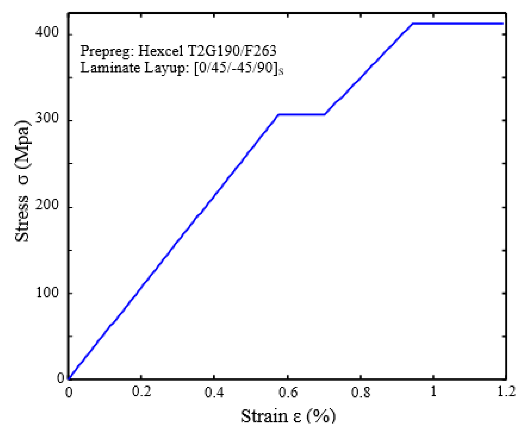
Based on the quasistatic mechanical properties of the UD composite laminates made of Hexcel T2G190/F263 prepregs as tabulated in Table 1, the theoretical quasistatic tensile stress–strain diagram of the present [0/±45/90]S composite laminate under uniaxial tension is predicted according to the classic laminate theory (CLT) [1] as shown in Figure 8, from which the predicted first ply failure occurs at the 90° plies, corresponding to the effective tensile stress of 311.11 MPa, provided that the ply failure of the composite laminate obeys the conservative maximum stress failure criterion as adopted in the CLT-based modeling. The theoretical predictions of the effective modulus and quasistatic tensile strength of the composite laminate are reasonably close to those determined in the present experiments, as shown in Figure 4 and Figure 5.
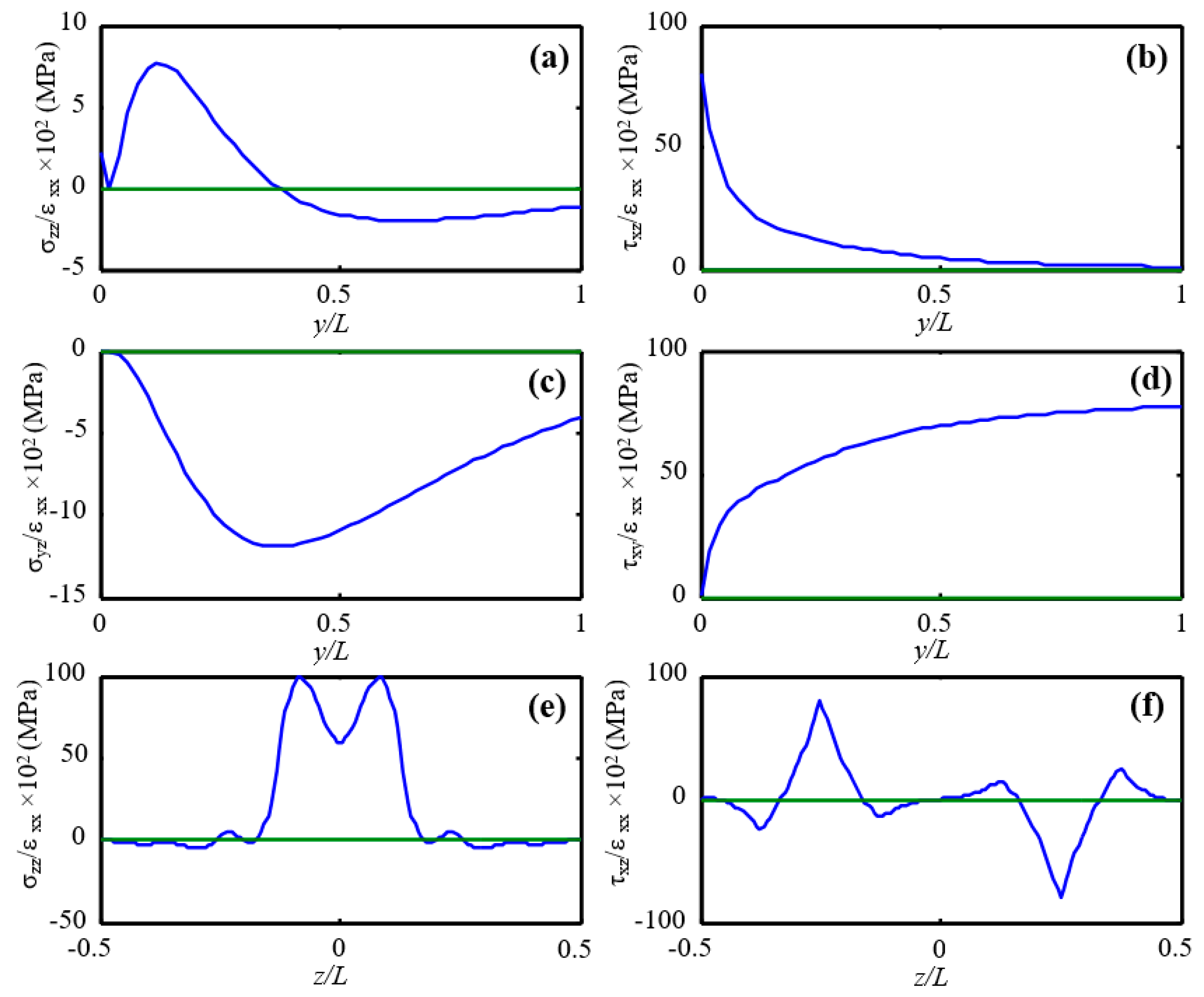
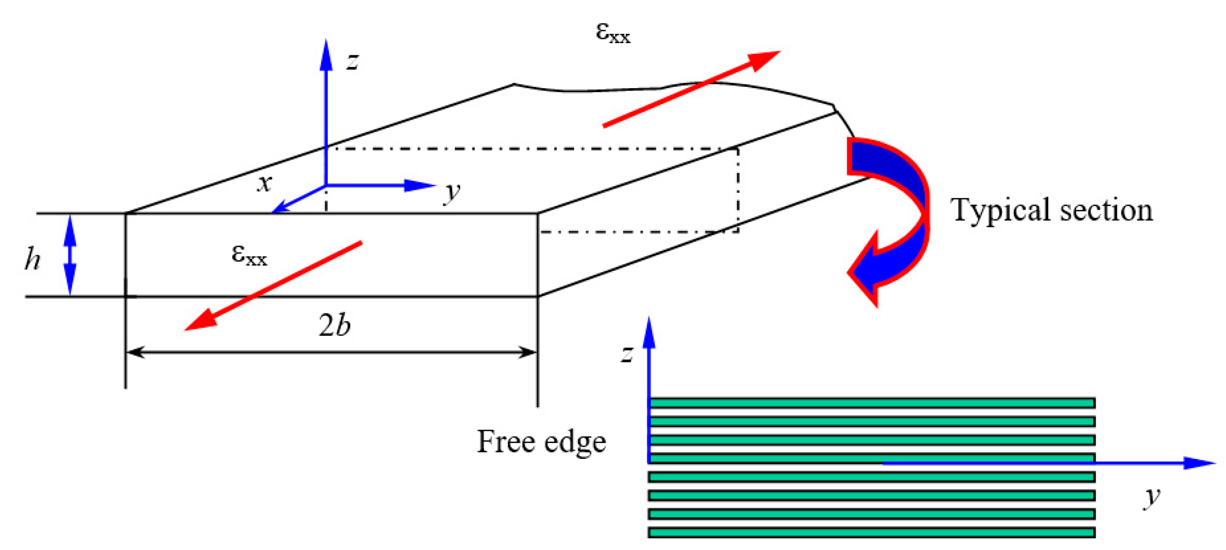
In addition, both the quasistatic tension and fatigue tests showed that edge-delamination first initiated at the 45°/90° interfaces of the composite laminate, i.e., the maximum normal stress σzz or out-of-plane shear τxz first appeared at the 45°/90° interfaces. To validate such maximum stresses at the 45°/90° interfaces of the laminate, the high-efficiency stress-function variational method initially formulated by Yin [79,80] and further refined and extended by Wu [14,45] is adopted for the free-edge stress analysis of this composite laminate (See Appendix A for detailed derivations). The mechanical properties of the UD Hexcel composite laminate provided in Table 1 are used in this free-edge stress analysis, and additional mechanical properties to be used are derived or reasonably assumed as G13 = 4.76 × 10³ MPa, G23 = 3.024 × 10³ MPa, ν23 = 0.46. The composite laminate with the layup of [0/±45/90]S is assumed to have a straight free-edge and a constant uniaxial strain εxx = 0.01 is applied along the global x-axis, as shown in Figure A1 in Appendix A. The predicted free-edge stresses of the laminate are shown in Figure 9, in which Figure 9a–d show the stress variations along the 45°/−45° interface within L-distance (L: Laminate thickness) from the free edge (left) and Figure 9e,f show the variations of the normal stress σzz and out-of-plane shear stress τxz across the laminate thickness at the free edge. It can be found from Figure 9e,f that the highly localized free-edge normal stress σzz and out-of-plane shear stress τxz reach the maximum values at the 45°/90° and −45°/45° interfaces, respectively, where possible edge-delamination initiation could appear when the laminate subjected to uniaxial tension along the x-axis as observed in the experiments. Therefore, the above stress-function variational method is a powerful tool that can be used conveniently for prediction of the edge-delamination initiation in angle-ply composite laminates subjected to quasistatic tension or tension–tension fatigue loading. In addition, this semianalytic method can be used for laminate layup sequence design and optimization for effective suppression of the high free-edge stresses in composite laminates.
4. Concluding Remarks
In this experimental study, quasistatic tension and tension–tension fatigue tests have been conducted for the determination of the quasistatic tensile strength and fatigue residual tensile strength and related probabilistic distributions of a composite laminate with a ply layup of [0/±45/90]S. Several conclusions can be drawn from the presented test results, data reduction and model-based simulations as follows.
- (1)
- The quasistatic tensile strength and fatigue residual tensile strength of the tested Hexcel composite laminate follow two-parameter Weibull distributions very well with the shape and scale parameters decreasing with increasing fatigue cycles.
- (2)
- The peak of the laminate failure probability density and the mean residual tensile strength decreases with increasing fatigue cycles, while the probabilistic distribution of the residual tensile strength of the composite laminate becomes more and more scattered with increasing fatigue cycles.
- (3)
- The effective uniaxial modulus and tensile strength predicted by the class laminate theory (CLT) were reasonably validated by the present experimental observations.
- (4)
- The present experimental observations showed that edge delamination first occurred at the 45°/90° interfaces of the composite laminate, corresponding to interfaces of the laminate with the maximum out-of-plane shear and normal stresses as predicted by the efficient stress-function variational method.
Furthermore, the present experimental study and related data reduction as well as strength and free-edge stress analysis of composite laminates indicate that the mechanical properties of PMC laminates have large variations due to various random factors involved in composite microstructures and processing. It is necessary to introduce the concept of probabilistic strength distribution in order to more accurately describe the mechanical behavior of PMC laminates and to predict their reliable performance and lifetime when integrated in composite structures.
Author Contributions
X.-F.W. conceived and performed the experimental and numerical studies. X.-F.W. and O.Z. analyzed the data and wrote the paper. Both authors have read and agreed to the published version of the manuscript.
Funding
The work performed at the North Dakota State University was partially supported by the NASA EPSCoR (NASA Grant #NNX07AK81A, seed grant: 43500-2490-FAR018640), NDSU Development Foundation (Grant No.: 43500-2490-FAR0017475), and DOE.
Acknowledgments
The experimental work was performed by Xiang-Fa Wu during his stay in Yuris A. Dzenis’s research group in the Department of Engineering Mechanics at University of Nebraska-Lincoln (UNL) (with financial support by the U.S. Army Research Office and the U.S. Air Force Office of Scientific Research to Dzenis at UNL).
Conflicts of Interest
The authors declare no conflict of interest.
Appendix A. Stress-Function Variational Method for Free-Edge Stress Analysis of Composite Laminates
Wu [14,45] refined and extended Yin’s stress-function variational method [79,80] for high-efficiency, accurate free-edge stress analysis of general angle-ply composite laminates made of an arbitrary number of UD composite plies. Consider a composite laminate with traction-free edges, as shown in Figure A1. Assume the laminate to be made of laminae with uniform thickness. Each ply (lamina) may be oriented at an arbitrary angle in the x-y plane. In the laminate coordinate system, the constitutive equation for each individual ply can be expressed in terms of the generalized Hooke’s law in a contracted notation [1,116,117] as
where Sij (i,j = 1,2,3…,6) are elements of the transformed compliance matrix, αi (i = 1,2,3) are the transformed thermal expansion coefficients, ∆T is the temperature change from a reference, stress-free condition, and subscript indices (1, 2, 3) stand for (x, y, z).
Figure A1.
Geometry and coordinate system for a laminate free-edge problem.

In Equation (A1), the following contracted notation is adopted
and Sij is the inverse transformed stiffness matrix in the (x, y, z)-coordinate system as
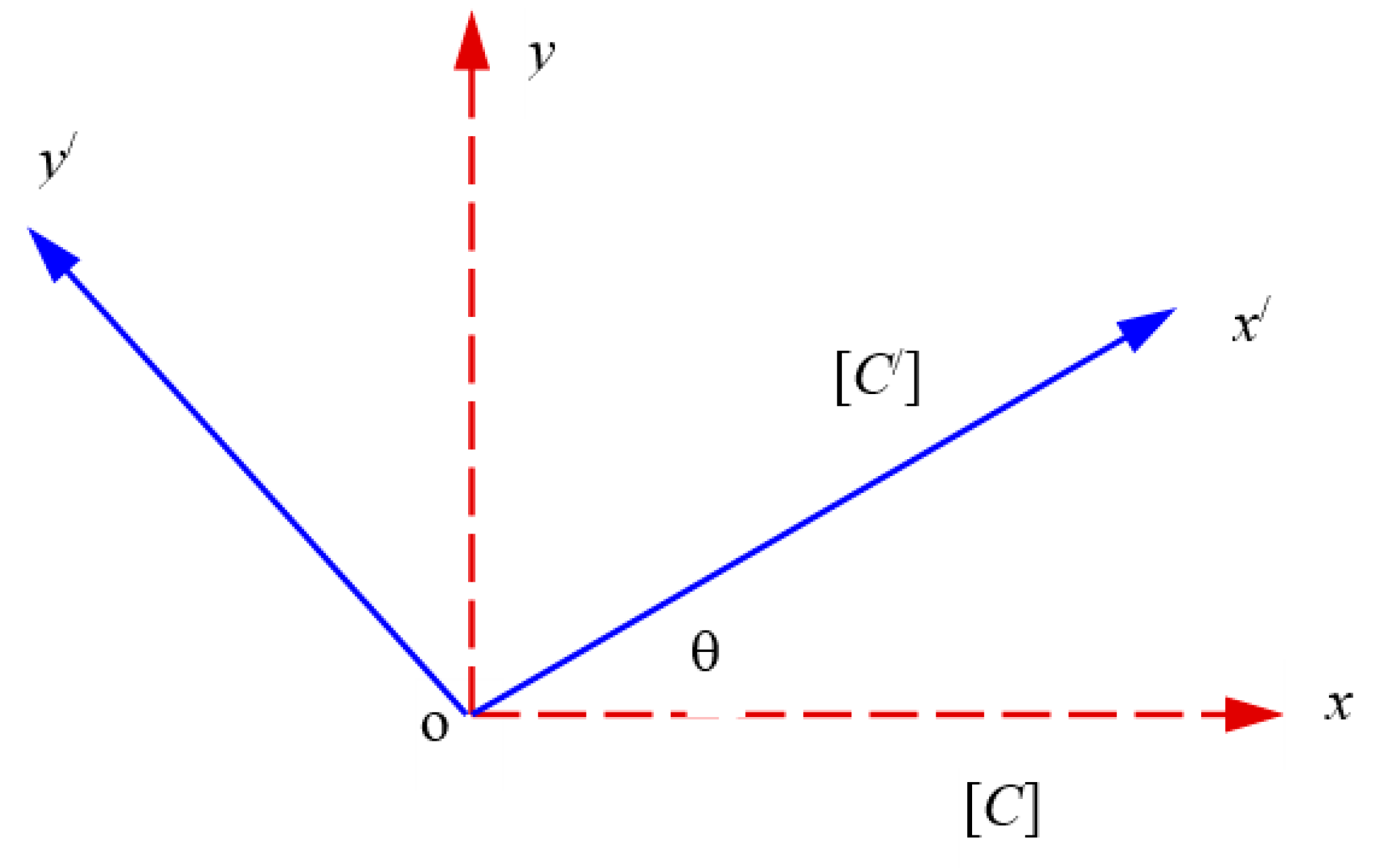
Here, introduce the transform of a ply stiffness matrix, which is used for stiffness transform between the ply-material coordinate system and the global coordinate system of the laminate. Consider a rotation of the original (x, y, z)-coordinate system along the z-axis to the current coordinate system (x/, y/, z/), as shown in Figure A2.
Figure A2.
Rotation of the coordinate system along z-direction.

The nonzero stiffness elements in the new coordinate system can be expressed in terms of in the original coordinate system as [116]
Traction-free boundary conditions of the laminate described in Figure A1 can be expressed as
The laminate is assumed to be in the state of plain strain in x-direction, which is characterized by specifying a constant strain value of ε1. Thus, the corresponding axial stress σ1 can be extracted from relation (A1) as
where the tensor summation rule is assumed. The constant strain value of ε1 can be reflected in the generalized Hooke’s law (A1) as
where
Since the laminate is in the plane strain state, two Lekhnitskii’s stress potentials F(y, z) and Ψ(y, z) [118] are introduced as
In the i-th layer, a nondimensional thickness coordinate η is defined as .
In the classic plate theory, the in-plane stresses vary linearly across the plate thickness, and this feature is approximately valid in each thin layer of a composite laminate. Thus, the stress function F in each ply can be approached by a polynomial function of degree three in η-direction (i.e., the thickness direction), while the stress function Ψ in each ply is approximated by another polynomial function of degree two in η-direction (i.e., the laminate width direction). In the i-th ply, the stress functions are assumed as t2Fi(y) and tΨi(y) on the interface z = zi and t2Fi−1(y) and tΨi−1(y) on z = zi−1, where t is the ply thickness. Thus, from (A9), the cubic polynomial approximation of the in-plane stress function in the i-th ply must have the following expressions
where Gi(y) and Gi−1(y) are the derivatives of Fi(y) and Fi−1(y), and F0(y) = G0(y) = Fn+1(y) = Gn+1(y) = 0 are related to the traction-free conditions on the lower and upper surfaces of the composite laminate.
The quadric polynomial approximation of the out-of-plane function in the i-th ply can be expressed as
where Hi(y) is the derivative of Gi(y) on the upper side of the same interface, which is generally discontinuous across the interface, and Ψ0(y) = Ψn+1(y) = 0 relates to the traction-free conditions on the lower and upper surfaces of the composite laminate.
The above two Lekhnitskii’s stress potentials F(y, z) and Ψ(y, z) are obtained by modifying those introduced by Yin [94,95] (introducing thickness t and then ensuring F, G, ψ and H with the same units). These modifications lead to a well-conditioned generalized eigenvalue problem, which can be solved efficiently even for a quite large matrix rank.
The governing equations are achieved by taking the stationary value of the complementary strain energy of the laminate per unit length as
By substituting (A10) and (A11) into (A12) and then integrating by parts and ply by ply, a system of variational equations is yielded as
where
and the global matrices W, V, and U are constant real-valued symmetric square matrices and b is a column relating the initial specified external and thermal strains, which are assembled from the element matrices We, Ve, Ue, and be in each ply as
where matrices (A15), (A16), and (A18) relate to vectors: , , and , and vector (A17) relates to vector .
It should be mentioned that the global coefficient matrices W, V, and U are real-valued symmetric square matrices, and coefficient matrix W of the differential operator d4/dx4 has the nontrivial elements only in a 2n × 2n square submatrix in the upper left corner. Equation (A13) is satisfied for arbitrary variations δH0, δF1, δG1, δΨ1, …, and δHn if and only if {Y} satisfies the following Euler–Lagrange equations (i.e., the weak solution)
with the homogenous boundary conditions at the free edges
To solve Equation (A19), one can first solve the corresponding homogenous equation by determining its eigenvalues and related eigenvectors. Thus, by assuming {Y} = {X0}exp(λy/t), one can obtain the corresponding generalized eigenvalue problem as
The particular solution to Equation (A19) can be determined as
which is the solution to an infinite laminate without edges subjected to the same axial strain, or the solution of the laminate far from the free edges. Separate the global matrices V and U into four submatrices respectively, and vector {X0} into two sub-vectors as
where {X10} = {F1, F2, …, Fn, G1, G2, …, Gn}T, and {X20} = {ψ1, ψ2, …, ψn, H0, H1, …, Hn}T. By introducing an auxiliary vector {X1} = λ2{X10}T, eigenvalue problem (A21) can be cast into a generalized eigenvalue problem as
where
and I is a diagonal unit matrix, and 0 is a zero matrix.
Generalized eigenvalue problem (A24) is well conditioned, and its eigenvalues and corresponding eigenvectors can be obtained using a standard mathematic program. The general eigenvalues and eigenvectors are complex-valued since matrices A and B are unsymmetrical. Numerical results show that a standard algorithm provided by MatLab is robust for regular laminates with the ply number n up to 70, which corresponds to a huge generalized unsymmetrical eigenvalue problem of the order 421. In the case of Equation (A21), assume the obtained eigenvalues are λi (i = 1, 2 … 6n + 1) and the corresponding eigenvectors are Φi (i = 1, 2, …, 6n + 1). Thus, the general solution to Equation (A19) can be obtained from a linear combination of the eigenvectors as
where (12n + 2) unknowns may be determined by (12n + 2) traction-free conditions as described in (A20). Because of the rapidly decaying exponential functions, in the calculations only a semi-infinite laminate with one free-edge needs to be considered. Thus, the general solution (A26) can be further simplified as
where λi (i = 1, 2, …, 6n + 1) are the eigenvalues with negative real parts, and the coefficients αi (i = 1, 2, …, 6n + 1) are determined by (6n + 1) traction-free conditions at y = 0 as described in (A20). Finally, the stress components can be extracted by substituting (A27) and (A14) into (A9).
References
- Jones, R.M. Mechanics of Composite Materials, 2nd ed.; Taylor and Francis: Philadelphia, PA, USA, 1999. [Google Scholar]
- Tsai, S.W. Three decades of composites activities at US Air Force Materials Laboratory. Compos. Sci. Technol. 2005, 65, 2295–2299. [Google Scholar] [CrossRef]
- Carlson, H.C.; Goretta, K.C. Basic materials research programs at the U.S. Air Force Office of Scientific Research. Mater. Sci. Eng. B 2006, 132, 2–7. [Google Scholar] [CrossRef] [Green Version]
- Trask, R.S.; Williams, G.J.; Bond, I.P. Self-healing polymer composites: Mimicking nature to enhance performance. Bioinspir. Biomim. 2007, 2, 1–9. [Google Scholar] [CrossRef] [PubMed]
- Mallick, P.K. Fiber-Reinforced Composites: Materials, Manufacturing, and Design; CRC Press: New York, NY, USA, 2007. [Google Scholar]
- Mohanty, A.K.; Vivekanandhan, S.; Pin, J.M.; Misra, M. Composites from renewable and sustainable resources: Challenges and innovations. Science 2018, 362, 536–542. [Google Scholar] [CrossRef] [Green Version]
- Elanchezhian, C.; Ramnath, B.V.; Ramakrishnan, G.; Rajendrakumar, M.; Naveenkumar, V.; Saravanakumar, M.K. Review on mechanical properties of natural fiber composites. Mater. Today Proc. 2018, 5, 1785–1790. [Google Scholar] [CrossRef]
- Parandoush, P.; Lin, D. A review on additive manufacturing of polymer fiber composites. Compos. Struct. 2017, 182, 36–53. [Google Scholar] [CrossRef]
- Sood, M.; Dwivedi, G. Effect of fiber treatment on flexural properties of natural fiber reinforced composites: A review. Egypt. J. Pet. 2018, 27, 775–783. [Google Scholar] [CrossRef]
- Wu, X.F.; Dzenis, Y.A. Determination of dynamic delamination toughness of a graphite-fiber/epoxy composite using Hopkinson pressure bar. Polym. Compos. 2005, 26, 165–180. [Google Scholar] [CrossRef] [Green Version]
- Wu, X.F.; Ghoshal, G.; Kartashov, M.; Aslan, Z.; Turner, J.A.; Dzenis, Y.A. Experimental characterization of the impact-damage tolerance of a cross-ply graphite-fiber/epoxy laminate. Polym. Compos. 2008, 29, 534–543. [Google Scholar] [CrossRef] [Green Version]
- Gdoutos, E.E.; Pilakoutas, K.; Rodopoulos, C.A. Failure Analysis of Industrial Composite Materials; McGraw-Hill: New York, NY, USA, 2000. [Google Scholar]
- Tay, T.E. Characterization and analysis of delamination fracture in composites: An overview of developments from 1990 to 2001. Appl. Mech. Rev. 2003, 56, 1–32. [Google Scholar] [CrossRef]
- Wu, X.F. Fracture of Advanced Composites with Nanostructured Interfaces: Fabrication, Characterization and Modeling; VDM Verlag Publishing House Ltd.: Saarbrücken, Germany, 2009. [Google Scholar]
- Hahn, H.T.; Kim, R.Y. Fatigue Behavior of Composite Laminate. J. Compos. Mater. 1976, 10, 156–180. [Google Scholar] [CrossRef]
- Reifsnider, K.L.; Shulter, K.; Duke, J.C. Long-Term Behavior of Composites, ASTM STP 813; American Society for Testing and Material: Philadelphia, PA, USA, 1983; pp. 136–159. [Google Scholar]
- Reifsnider, K.L. Fatigue of Composite Materials; Elsevier: Oxford, UK, 1991. [Google Scholar]
- Diao, X.X.; Ye, L.; Mai, Y.W. Fatigue behavior of CF/PEEK composite laminate made from commingled prepreg. I: Experimental studies. Compos. Part A Appl. Sci. Manuf. 1997, 28, 739–747. [Google Scholar] [CrossRef]
- Diao, X.X.; Mai, Y.W. Fatigue life prediction of composite laminates using a stress redistribution function. J. Reinf. Plast. Compos. 1996, 15, 249–266. [Google Scholar] [CrossRef]
- Diao, X.X.; Ye, L.; Mai, Y.W. Fatigue behavior of CF/PEEK composite laminate made from commingled prepreg. II: Statistical simulations. Compos. A Appl. Sci. Manuf. 1997, 28, 734–755. [Google Scholar]
- Wu, D. Studies of Damage Evaluation in Advanced Polymer Matrix Composites Subjected to Thermomechanical Fatigue. Master’s Thesis, University of Nebraska, Lincoln, NE, USA, 2000. [Google Scholar]
- Wu, X.F.; Dzenis, Y.A. Rate effects on mode-I delamination toughness of a graphite/epoxy laminated composite. Int. J. Fract. 2001, 112, L9–L12. [Google Scholar] [CrossRef]
- Dzenis, Y.A. Cycle-based analysis of damage and failure in advanced composites under fatigue. I: Experimental observation of damage development with loading cycles. Int. J. Fatigue 2003, 25, 499–510. [Google Scholar] [CrossRef]
- Dzenis, Y.A. Cycle-based analysis of damage and failure in advanced composites under fatigue. II: Stochastic mesomechanics modeling. Int. J. Fatigue 2003, 25, 499–510. [Google Scholar] [CrossRef]
- Dzenis, Y.A.; Saunders, I. On the possibility of discrimination of mixed mode fatigue fracture mechanisms in adhesive composite joints by advanced acoustic emission analysis. Int. J. Fract. 2002, 117, L23–L28. [Google Scholar] [CrossRef]
- Rudov-Clark, S.; Mouritz, A.P. Tensile fatigue properties of a 3D orthogonal woven composite. Compos. A Appl. Sci. Manuf. 2008, 39, 1018–1024. [Google Scholar] [CrossRef]
- Cista, J.; Turon, A.; Trias, D.; Blanco, N.; Mayugo, J.A. A progressive damage model for unidirectional fibre-reinforced composites based on fibre fragmentation. Part II: Stiffness reduction in environment sensitive fibres under fatigue. Compos. Sci. Technol. 2005, 65, 2269–2275. [Google Scholar]
- Takeda, N.; Kobayashi, S.; Ogihara, S.; Kobayashi, A. Effects of toughened interlaminar layers on fatigue damage progress in quasi-isotropic CFRP laminates. Int. J. Fatigue 1999, 21, 235–242. [Google Scholar] [CrossRef]
- Atodaria, D.R.; Putatunda, S.K.; Mallick, P.K. Delamination growth behavior of a fabric reinforced laminated composite under mode I fatigue. J. Eng. Mater. Technol. 1999, 121, 381–385. [Google Scholar] [CrossRef]
- Assimina, A.P. Evolution of interlayer and intralayer cracks under compressive fatigue in composites. J. Eng. Mater. Technol. 1999, 121, 430–435. [Google Scholar]
- Asp, L.E.; Sjogren, A.; Greenhalgh, E.S. Delamination growth and thresholds in a carbon/epoxy composite under fatigue loading. J. Compos. Sci. Technol. 2001, 23, 55–68. [Google Scholar]
- McNulty, J.C.; He, M.Y.; Zok, F.W. Notch sensitivity of fatigue life in a SylramicTM/SiC composite at elevated temperature. Compos. Sci. Technol. 2001, 61, 1331–1338. [Google Scholar] [CrossRef]
- Bureau, M.N.; Perrin, F.; Denault, J.; Dickson, J.I. Interlaminar fatigue crack propagation in continuous glass fiber/polypropylene composites. Int. J. Fatigue 2002, 24, 99–108. [Google Scholar] [CrossRef]
- Sisodia, S.M.; Gamstedt, E.K.; Edgren, F.; Varna, J. Effects of voids on quasi-static and tension fatigue behavior of carbon-fibre composite laminates. J. Compos. Mater. 2015, 49, 2137–2148. [Google Scholar] [CrossRef]
- ASTM D 6115-97. Standard test method for mode I fatigue delamination growth onset of unidirectional fiber-reinforced polymer matrix composites. In Annual Book of ASTM Standards, 15.03; American Society for Testing and Materials: Philadelphia, PA, USA, 2000. [Google Scholar]
- ASTM D 6671-01. Standard test method for mixed-mode fatigue delamination growth onset of unidirectional fiber-reinforced polymer matrix composites. In Annual Book of ASTM Standards, 15.03; American Society for Testing and Materials: Philadelphia, PA, USA, 2000. [Google Scholar]
- Berthelot, J.M. Transverse cracking and delamination in cross-ply glass-fiber and carbon-fiber reinforced plastic laminates: Static and fatigue Loading. Appl. Mech. Rev. 2003, 56, 111–146. [Google Scholar] [CrossRef]
- Bak, B.L.V.; Sarrado, C.; Turon, A.; Costa, J. Delamination under fatigue loads in composite laminates: A review on the observed phenomenology and computational methods. Appl. Mech. Rev. 2014, 66, 060803. [Google Scholar] [CrossRef]
- Degrieck, J.; Paepegem, W.V. Fatigue damage modeling of fiber-reinforced composite materials: A review. Appl. Mech. Rev. 2001, 54, 279–300. [Google Scholar] [CrossRef]
- Sevenois, R.D.B.; Paepegem, W.V. Fatigue damage modeling techniques for textile composites: Review and comparison with unidirectional composite modeling techniques. Appl. Mech. Rev. 2015, 67, 020802. [Google Scholar] [CrossRef]
- Yang, J.N. Fatigue and residual strength degradation for graphite/epoxy composites under tension-compression cyclic loadings. J. Compos. Mater. 1978, 12, 19–39. [Google Scholar] [CrossRef]
- Hashin, Z. Cumulative damage theory for composites: Residual life and residual strength methods. Compos. Sci. Technol. 1985, 23, 1–19. [Google Scholar] [CrossRef]
- Rotem, A. Fatigue and residual strength of composite laminates. Eng. Fract. Mech. 1986, 25, 819–827. [Google Scholar] [CrossRef]
- Diao, X.; Ye, L.; Mai, Y.M. A statistical model of residual strength and fatigue life of composite laminate. Compos. Sci. Technol. 1995, 54, 329–336. [Google Scholar] [CrossRef]
- Whitworth, H.A. Evaluation of the residual strength degradation in composite laminates under fatigue loading. Compos. Struct. 2000, 48, 261–264. [Google Scholar] [CrossRef]
- Paepegem, W.V.; Degrieck, J. A new coupled approach of residual stiffness and strength for fatigue fibre-reinforced composites. Int. J. Fatigue 2002, 24, 747–762. [Google Scholar] [CrossRef]
- Tserpes, K.I.; Papankos, P.; Labeas, G.; Pantelakis, S.P. Fatigue damage accumulation and residual strength assessment of CFRP laminates. Compos. Struct. 2004, 63, 219–230. [Google Scholar] [CrossRef]
- Philippidis, T.P.; Passipoularidis, V.A. Residual strength after fatigue in composites: Theory vs. experiment. Int. J. Fatigue 2007, 29, 2104–2116. [Google Scholar] [CrossRef]
- Ma, Y.; Zhang, Y.; Sugahara, T.; Jin, S.; Yang, Y.; Hamada, H. Off-axis tensile fatigue assessment based on residual strength for the unidirectional 45 carbon fiber-reinforced composites at room temperature. Compos. Part A Appl. Sci. Manuf. 2016, 90, 711–723. [Google Scholar] [CrossRef]
- Llobet, J.; Maimi, P.; Mayugo, J.A.; Essa, Y.; de la Escalera, F.M. A fatigue damage and residual strength model for unidirectional carbon/epoxy composites under on-axis tension-tension loadings. Int. J. Fatigue 2017, 103, 508–515. [Google Scholar] [CrossRef]
- Mejri, M.; Toubal, L.; Cuillière, J.C.; François, V. Fatigue life and residual strength of a short-natural-fiber-reinforced plastic vs Nylon. Compos. Part B Eng. 2017, 110, 429–441. [Google Scholar] [CrossRef]
- D’Amore, A.; Grassia, L. Principal feature of fatigue and residual strength of composite material subjected to constant amplitude (CA) loading. Materials 2019, 12, 2586. [Google Scholar] [CrossRef] [PubMed] [Green Version]
- D’Amore, A.; Grassia, L. Comparative study of phenomenological residual strength models for composite materials subjected to fatigue: Predictions at constant amplitude (CA) loading. Materials 2019, 12, 3398. [Google Scholar] [CrossRef] [PubMed] [Green Version]
- Ganesan, C.; Joanna, P.S. Modeling the residual strength and fatigue life of carbon fiber composites under constant amplitude loading. Mech. Adv. Mater. Struct. 2020, 27, 1840–1848. [Google Scholar] [CrossRef]
- D’Amore, A.; Caprino, G.; Stupak, P.; Zhou, J.; Nicolais, L. Effect of stress ratio on the flexural fatigue behavior of continuous strand mat reinforced plastics. Sci. Eng. Compos. Mater. 1996, 5, 1–8. [Google Scholar] [CrossRef]
- Dzenis, Y.A.; Reneker, D.H. Delamination Resistant Composites Prepared by Small Diameter Fiber Reinforced at Ply Interface. U.S. Patent 6265333, 24 July 2001. [Google Scholar]
- Dzenis, A. Structural nanocomposites. Science 2008, 319, 419–420. [Google Scholar] [CrossRef]
- Sergiyenko, S. Experimental Analysis of Delamination in Laminated Composites with Nanoreinforced Interfaces. Master’s Thesis, University of Nebraska, Lincoln, NE, USA, 2000. [Google Scholar]
- Gokdag, E. Static and Fatigue Interlaminar Fracture of Graphite-Epoxy Composites with PAN Nanofiber Reinforcement at Interfaces. Master’s Thesis, University of Nebraska, Lincoln, NE, USA, 2001. [Google Scholar]
- Wu, X.F. Fracture of Advanced Polymer Composites with Nanofiber Reinforced Interfaces. Ph.D. Thesis, University of Nebraska, Lincoln, NE, USA, 2003. [Google Scholar]
- Sinha-Ray, S.; Pelot, D.D.; Zhou, Z.P.; Rahman, A.; Wu, X.F.; Yarin, A.L. Encapsulation of self-healing materials by coelectrospinning, emulsion electrospinning, solution blowing and intercalation. J. Mater. Chem. 2012, 22, 9138–9146. [Google Scholar] [CrossRef]
- Wu, X.F.; Rahman, A.; Zhou, Z.; Pelot, D.D.; Singa-Ray, S.; Chen, B.; Payne, S.; Yarin, A.L. Electrospinning core-shell nanofibers for interfacial toughening and self-healing of carbon-fiber/epoxy composites. J. Appl. Polym. Sci. 2013, 129, 1383–1393. [Google Scholar] [CrossRef]
- Wu, X.F.; Yarin, Y.L. Recent progress in interfacial toughening and damage self-healing of polymer composites based on electrospun and solution-blown nanofibers: An overview. J. Appl. Polym. Sci. 2013, 130, 2225–2237. [Google Scholar] [CrossRef]
- Chen, Q.; Zhang, L.F.; Rahman, A.; Zhou, Z.P.; Wu, X.F.; Fong, H. Hybrid multi-scale epoxy composite made of conventional carbon fiber fabrics with interlaminar regions containing electrospun carbon nanofiber mats. Compos. Part A Appl. Sci. Manuf. 2011, 42, 2036–2042. [Google Scholar] [CrossRef]
- Chen, Q.; Zhang, L.F.; Yoon, M.K.; Wu, X.F.; Arefin, R.H.; Fong, H. Preparation and evaluation of nano-epoxy composite resins containing electrospun glass nanofibers. J. Appl. Polym. Sci. 2012, 124, 444–451. [Google Scholar] [CrossRef]
- Chen, Q.; Zhang, L.F.; Zhao, Y.; Wu, X.F.; Fong, H. Hybrid multi-scale composites developed from glass microfiber fabrics and nano-epoxy resins containing electrospun glass nanofibers. Compos. Part B Eng. 2012, 43, 309–316. [Google Scholar] [CrossRef]
- Chen, Q.; Zhao, Y.; Zhou, Z.P.; Rahman, A.; Wu, X.F.; Wu, W.D.; Xu, T.; Fong, H. Fabrication and mechanical properties of hybrid multi-scale epoxy composites reinforced with conventional carbon fiber fabrics surface-attached with electrospun carbon nanofiber mats. Compos. Part B Eng. 2013, 44, 1–7. [Google Scholar] [CrossRef]
- Wu, X.F.; Zholobko, O.; Zhou, Z.; Rahman, A. Electrospun nanofibers for interfacial toughening and damage self-healing of polymer composites and surface coatings. In Electrospun Polymers and Composites: Ultrafine Materials, High. Performance Fibers and Wearables; Woodhead Publishing Ltd.: Cambridge, UK, 2020; pp. 315–359. [Google Scholar]
- Brugo, T.M.; Minak, G.; Zucchelli, A.; Saghafi, H.; Fotouhi, M. An investigation on the fatigue based delamination of woven carbon-epoxy composite laminates reinforced with polyamide nanofibers. Procedia Eng. 2015, 109, 65–72. [Google Scholar] [CrossRef] [Green Version]
- Daelemans, L.; van der Heijden, S.; Baere, I.D.; Rahier, H.; Paepegem, W.V. Improved fatigue delamination behavior of composite laminates with electrospun thermoplastic nanofibrous interleaves susing the central cut-ply method. Compos. Part A Appl. Sci. Manuf. 2017, 94, 10–20. [Google Scholar] [CrossRef]
- Fotouhi, M.; Fragassa, C.; Fotouhi, S.; Saghafi, H.; Minak, G. Damage characterization of nano-interleaved CFRP under static and fatigue loading. Fibers 2019, 7, 13. [Google Scholar] [CrossRef] [Green Version]
- Reneker, D.H.; Chun, I. Nanometre diameter fibres of polymer, produced by electrospinning. Nanotechnology 1996, 77, 216–223. [Google Scholar] [CrossRef] [Green Version]
- Reneker, D.H.; Yarin, A.L.; Zussman, E.; Xu, H. Electrospinning of nanofibers from polymer solutions and melts. Adv. Appl. Mech. 2007, 41, 43–195. [Google Scholar]
- Reneker, D.H.; Yarin, A.L. Electrospinning jets and polymer nanofibers. Polymer 2008, 49, 2387–2425. [Google Scholar] [CrossRef] [Green Version]
- Reneker, D.H.; Yarin, A.L.; Fong, H.; Koombhongse, S. Bending instability of electrically charged liquid jets of polymer solutions in electrospinning. J. Appl. Phys. 2000, 87, 4531–4547. [Google Scholar] [CrossRef] [Green Version]
- Yarin, A.L.; Koombhongse, S.; Reneker, D.H. Bending instability in electrospinning of nanofibers. J. Appl. Phys. 2001, 89, 3018–3026. [Google Scholar] [CrossRef] [Green Version]
- Huang, Z.M.; Zhang, Y.Z.; Kotaki, M.; Ramakrishna, S. A review on polymer nanofibers by electrospinning and their applications in nanocomposites. Compos. Sci. Technol. 2003, 63, 2223–2253. [Google Scholar] [CrossRef]
- Dzenis, Y. Spinning continuous fibers for nanotechnology. Science 2004, 304, 1917–1919. [Google Scholar] [CrossRef]
- Li, D.; Xia, Y.N. Electrospinning of nanofibers: Reinventing the wheel? Adv. Mater. 2004, 16, 1151–1170. [Google Scholar] [CrossRef]
- Theron, A.; Yarin, A.L.; Zussman, E.; Kroll, E. Multiple jets in electrospinning: Experiment and modeling. Polymer 2005, 46, 2889–2899. [Google Scholar] [CrossRef]
- Yarin, A.L.; Zussman, E. Upward needleless electrospinning of multiple nanofibers. Polymer 2004, 45, 2977–2980. [Google Scholar] [CrossRef]
- Chronakis, I.S. Novel nanocomposites and nanoceramics based on polymer nanofibers using electrospinning process-A review. J. Mater. Proc. Technol. 2005, 167, 283–293. [Google Scholar] [CrossRef]
- Ramaseshan, R.; Sundarrajan, S.; Jose, R.; Ramakrishna, S. Nanostructured ceramics by electrospinning. J. Appl. Phys. 2007, 102, 111101. [Google Scholar] [CrossRef]
- Greiner, A.; Wendorff, J.H. Electrospinning: A fascinating method for the preparation of ultrathin fibers. Angew. Chem. Int. Ed. 2007, 46, 5670–5703. [Google Scholar] [CrossRef]
- Ramakrishna, S.; Fujihara, K.; Teo, W.E.; Lim, T.C.; Ma, Z. An Introduction to Electrospinning and Nanofibers; World Scientific Press: Singapore, 2005. [Google Scholar]
- Lukas, D.; Sarkar, A.; Martinova, L.; Vodsed’alkova, K.; Lubasova, D.; Chaloupek, J.; Pokorny, P.; Mikes, P.; Chvojka, J.; Komarek, M. Physical principles of electrospinning (Electrospinning as a nano-scale technology of the twenty-first century). Text. Prog. 2009, 41, 59–140. [Google Scholar] [CrossRef]
- Nayak, R.; Padhye, R.; Kyratzis, I.L.; Truong, Y.B.; Arnold, L. Recent advances in nanofibre fabrication techniques. Text. Res. J. 2011, 82, 129–149. [Google Scholar] [CrossRef]
- Persano, L.; Camposeo, A.; Tekmen, C.; Pisignano, D. Industrial upscaling of electrospinning and applications of polymer nanofibers: A review. Macromol. Mater. Eng. 2013, 298, 504–520. [Google Scholar] [CrossRef]
- Zhou, Z.; Wu, X.F.; Ding, Y.; Zhao, Y.; Jiang, L.; Xuan, C.; Sun, C. Needless emulsion electrospinning for scalable fabrication of core-shell nanofibers. J. Appl. Polym. Sci. 2014, 131, 40896. [Google Scholar] [CrossRef]
- Mohammadzadehmoghadam, S.; Dong, Y.; Davies, I.J. Recent progress in electrospun nanofibers: Reinforcement effect and mechanical performance. J. Polym. Sci. Part B Polym. Phys. 2015, 53, 1171–1212. [Google Scholar] [CrossRef]
- Wu, X.F.; Zhou, Z.; Zholobko, O.; Jenniges, J.J.; Baatz, B.; Ahmadi, M.; Chen, J. Critical condition of electrohydrodynamic jetting from a polymer-solution droplet on a conductive wire. J. Appl. Phys. 2020, 127, 054303. [Google Scholar] [CrossRef]
- Pipes, R.B.; Pagano, N.J. Interlaminar stresses in composite laminates under uniform axial extension. J. Compos. Mater. 1970, 4, 538–548. [Google Scholar] [CrossRef]
- Pagano, N.J. On the calculation of interlaminar normal stress in composite laminate. J. Compos. Mater. 1974, 8, 65–81. [Google Scholar] [CrossRef]
- Yin, W.L. Free edge effects in anisotropic laminates under extension, bending and twisting. Part I: A stress-function-based variational approach. J. Appl. Mech. 1994, 61, 410–415. [Google Scholar] [CrossRef]
- Yin, W.L. Free edge effects in anisotropic laminates under extension, bending and twisting. Part II: Eigenfunction analysis and the results for symmetric laminates. J. Appl. Mech. 1994, 61, 416–421. [Google Scholar] [CrossRef]
- Flanagan, G. An efficient stress function approximation for the free-edge stresses in laminates. Int. J. Solids Struct. 1994, 31, 941–952. [Google Scholar] [CrossRef]
- Hsu, P.W.; Herakovich, C.T. Edge effects in angle-ply composite laminates. J. Compos. Mater. 1977, 11, 422–428. [Google Scholar] [CrossRef]
- Wang, A.S.D.; Crossman, F.W. Calculation of edge stresses in multilayer laminates by sub-structuring. J. Compos. Mater. 1978, 12, 76–83. [Google Scholar] [CrossRef]
- Spilker, R.L.; Chou, S.C. Edge effects in symmetric composite laminates: Importance of satisfying the traction-free-edge condition. J. Compos. Mater. 1980, 14, 2–20. [Google Scholar]
- Altus, A.; Rotem, A.; Shmueli, M. Free edge effect in angle ply laminates—A new three dimensional finite difference solution. J. Compos. Mater. 1980, 14, 21–30. [Google Scholar]
- Wang, S.S.; Choi, I. Boundary-layer effects in composite laminates. Part 1: Free-edge stress singularities. J. Appl. Mech. 1982, 49, 541–548. [Google Scholar] [CrossRef]
- Wang, S.S.; Choi, I. Boundary-layer effects in composite laminates. Part 2: Free-edge stress solutions and basic characteristics. J. Appl. Mech. 1982, 49, 549–560. [Google Scholar] [CrossRef]
- Kassapoglou, C.; Lagace, P.A. An efficient method for the calculation of interlaminar stresses in composite materials. J. Appl. Mech. 1986, 53, 744–750. [Google Scholar] [CrossRef]
- Ye, L. Some characteristics of distributions of free-edge interlaminar stresses in composite laminates. Int. J. Solids Struct. 1990, 26, 331–351. [Google Scholar]
- Mittelstedt, C.; Becker, W. Free-edge effects in composite laminates. Appl. Mech. Rev. 2007, 60, 217–245. [Google Scholar] [CrossRef]
- Wu, X.F.; Dzenis, Y.A. Experimental determination of probabilistic edge-delamination of a graphite-fiber/epoxy composite. Compos. Struct. 2005, 70, 100–108. [Google Scholar] [CrossRef] [Green Version]
- Wu, X.F.; Jenson, R.A. Stress-function variational method for stress analysis of bonded joints under mechanical and thermal loads. Int. J. Eng. Sci. 2011, 49, 279–294. [Google Scholar] [CrossRef]
- Wu, X.F.; Jenson, R.A. Semi-analytic stress-function variational approach for the interfacial stresses in bonded joints. J. Eng. Mech. 2014, 140, 1–11. [Google Scholar] [CrossRef] [Green Version]
- Wu, X.F.; Zhao, Y.H. Stress-function variational method for interfacial stress analysis of adhesively bonded joints. Int. J. Solids Struct. 2013, 50, 4305–4319. [Google Scholar] [CrossRef] [Green Version]
- Wang, X. Stress-Function Variational Methods for Stress Analysis of Composite Laminates and Adhesively Bonded Composite Joints. Master’s Thesis, North Dakota State University, Fargo, ND, USA, 2015. [Google Scholar]
- Wu, X.F.; Jenson, R.A.; Zhao, Y. Stress-function variational approach to the interfacial stresses and progressive cracking in surface coatings. Mech. Mater. 2014, 69, 195–203. [Google Scholar] [CrossRef]
- Minak, G.; Morelli, P.; Zucchelli, A. Fatigue residual strength of circular laminate graphite-epoxy composite plates damaged by transverse load. Compos. Sci. Technol. 2009, 69, 1358–1363. [Google Scholar] [CrossRef] [Green Version]
- ASTM D 3039/D3039M-17, Standard Test Method for Tensile Properties of Polymer Matrix Composite Materials; ASTM International: West Conshohocken, PA, USA, 2017.
- ASTM D 3479/D3479M-19, Standard Test Method for Tension-Tension Fatigue of Polymer Matrix Composite Materials; ASTM International: West Conshohocken, PA, USA, 2019.
- Haidyrah, A.S.; Newkirk, J.W.; Castaño, C.H. Weibull statistical analysis of Krouse type bending fatigue of nuclear material. J. Nucl. Mater. 2016, 470, 244–250. [Google Scholar] [CrossRef]
- Christensen, R.M. Mechanics of Composite Materials; Wiley: New York, NY, USA, 1979. [Google Scholar]
- Ting, T.C.T. Anisotropic Elasticity: Theory and Applications; Oxford University Press: Oxford, UK, 1996. [Google Scholar]
- Lekhnitskii, S.G. Theory of Elasticity of an Anisotropic Body; Holden-Day: San Francisco, CA, USA, 1968. [Google Scholar]
Figure 1.
Schematic assembly of the two-chamber press-clave for PMC curing [14].
Figure 1.
Schematic assembly of the two-chamber press-clave for PMC curing [14].

Figure 2.
Curing cycle of the Hexcel T2G-190-12-F263 prepregs.

Figure 3.
Rectangular specimens of the composite laminate with a [0/±45/90]S layup. (Specimen dimensions: 135 mm × 15 mm × 1.35 mm).
Figure 3.
Rectangular specimens of the composite laminate with a [0/±45/90]S layup. (Specimen dimensions: 135 mm × 15 mm × 1.35 mm).

Figure 4.
Typical quasistatic stress–strain diagrams of the composite specimens. (a) Before fatigue test, (b) after 2000-cycle fatigue loading, (c) after 10,000-cycle fatigue loading (In this specific case, the ultimate residual tensile strength after 10,000-cycle fatigue loading is higher than that after 2000-cycle fatigue loading due to the scattering behavior of the ultimate tensile strength), and (d) after 10,000-cycle fatigue loading.

Figure 5.
Variation of the survival probabilities with the residual tensile strength.

Figure 6.
Variation of the survival probability with the residual tensile strength (in logarithmic scale).
Figure 6.
Variation of the survival probability with the residual tensile strength (in logarithmic scale).

Figure 7.
Variation of the failure probability density with the residual tensile strength.

Figure 8.
Predicted uniaxial tensile stress–strain diagram based on the classic laminate theory (CLT).
Figure 8.
Predicted uniaxial tensile stress–strain diagram based on the classic laminate theory (CLT).

Figure 9.
Predicted free-edge stresses based on stress-function variational method (L: laminate thickness, 1.35 mm; εxx = 0.01 in simulation; laminate (x, y, z)-coordinate system according to Figure A1). (a) Normal stress σzz along 45°/−45° interface within L-distance free edge (left); (b) out-of-plane shear stress τxz along 45°/−45° interface within L-distance free edge (left); (c) in-plane shear stress τyz along 45°/−45° interface within L-distance free edge (left); (d) in-plane shear stress τxy along 45°/−45° interface within L-distance free edge (left); (e) normal stress σzz across laminate thickness at the left free edge; (f) out-of-plane shear stress τxz across laminate thickness at the free edge.


Table 1.
In-plane mechanical properties of the UD carbon-fiber/epoxy composite laminate made of Hexcel T2G190/F263 prepregs [14].
Table 1.
In-plane mechanical properties of the UD carbon-fiber/epoxy composite laminate made of Hexcel T2G190/F263 prepregs [14].
| Mechanical Properties in Material Coordinate System | Values |
|---|---|
| Young’s modulus in the fiber direction, E1 (GPa) | 132.7 |
| Young’s modulus transverse to fiber direction, E2 (GPa) | 8.83 |
| In-plane shear modulus, G12 (GPa) | 4.76 |
| Poisson’s ratio, ν12 | 0.36 |
| Poisson’s ratio, ν21 | 0.03 |
| Ultimate tensile stress in the fiber direction, X1T (MPa) | 1462 |
| Ultimate tensile stress transverse to fiber direction, X2T (MPa) | 47.7 |
| Ultimate in-plane shear stress, S6 (MPa) | 82.0 |
| Ultimate tensile strain in the fiber direction, ε1T (%) | 1.10 |
| Ultimate tensile strain transverse to fiber direction, ε2T (%) | 0.52 |
| Ultimate in-plane shear strain, γ12 ult (%) | 4.06 |
Table 2.
Model parameters of the two-parameter Weibull distribution models based on maximum-likelihood estimation.
Table 2.
Model parameters of the two-parameter Weibull distribution models based on maximum-likelihood estimation.
| No. of Samples | Shape Parameter m | Dimensional Parameter σ0 (MPa) | Mean Strength (MPa) | Coefficient R | |
|---|---|---|---|---|---|
| Quasistatic test | 27 | 11.015 | 390.074 | 372.560 | 0.97127 |
| 2000-cycle fatigue test | 12 (2 failed) | 9.766 | 370.508 | 352.131 | 0.97409 |
| 10,000-cycle fatigue test | 12 (4 failed) | 5.926 | 341.511 | 316.615 | 0.94804 |
Publisher’s Note: MDPI stays neutral with regard to jurisdictional claims in published maps and institutional affiliations. |
© 2020 by the authors. Licensee MDPI, Basel, Switzerland. This article is an open access article distributed under the terms and conditions of the Creative Commons Attribution (CC BY) license (http://creativecommons.org/licenses/by/4.0/).
Share and Cite
MDPI and ACS Style
Wu, X.-F.; Zholobko, O. Experimental Study of the Probabilistic Fatigue Residual Strength of a Carbon Fiber-Reinforced Polymer Matrix Composite. J. Compos. Sci. 2020, 4, 173. https://0-doi-org.brum.beds.ac.uk/10.3390/jcs4040173
AMA Style
Wu X-F, Zholobko O. Experimental Study of the Probabilistic Fatigue Residual Strength of a Carbon Fiber-Reinforced Polymer Matrix Composite. Journal of Composites Science. 2020; 4(4):173. https://0-doi-org.brum.beds.ac.uk/10.3390/jcs4040173
Chicago/Turabian StyleWu, Xiang-Fa, and Oksana Zholobko. 2020. "Experimental Study of the Probabilistic Fatigue Residual Strength of a Carbon Fiber-Reinforced Polymer Matrix Composite" Journal of Composites Science 4, no. 4: 173. https://0-doi-org.brum.beds.ac.uk/10.3390/jcs4040173