
Assessment of Replacement of Metal Parts by BFRP Composites into a Highly Efficient Electrical Prototype


1
ENIDH, Escola Superior Náutica Infante D. Henrique, Av. Eng. Bonneville Franco, 2770-058 Paço de Arcos, Portugal
2
IDMEC, Instituto Superior Técnico, Universidade de Lisboa, Av. Rovisco Pais, 1, 1049-001 Lisboa, Portugal
3
CDP2T, Escola Superior de Tecnologia de Setúbal, Campus do IPS, Estefanilha, 2914-508 Setúbal, Portugal
*
Author to whom correspondence should be addressed.
J. Compos. Sci. 2021, 5(4), 95; https://0-doi-org.brum.beds.ac.uk/10.3390/jcs5040095
Submission received: 5 March 2021
/
Revised: 24 March 2021
/
Accepted: 29 March 2021
/
Published: 1 April 2021
(This article belongs to the Special Issue Feature Papers in Journal of Composites Science in 2021)
Abstract
:This work intends to evaluate the use of epoxy composite materials reinforced with basalt fibers as replacement to metallic mechanical parts of a highly efficient electrical prototype. The analysis of the behavior of the original metallic bracket was made and an optimization process was carried out in order to achieve the most suitable geometry and stacking sequence if produced in composite material. Finite element analysis using Siemens NX12 and experimental tests to the produced composite part were performed in order to access it. It was verified that the total weight of the composite part shows a 45% reduction. The composite part shows a higher deformation than the metallic one due to basalt fiber’s higher flexibility. However, the advantages added by the new component largely compensate for the disadvantages that may have been added without compromising its performance. Obtained results show that the use of basalt fiber reinforced composites as the material of mechanical parts of a highly efficient electrical prototype that is a good alternative.
1. Introduction
In recent decades, there has been an exponential increase in the use of composite materials throughout the industry, with a special focus on aeronautics and the automotive industry [1,2,3,4]. The use of these materials is largely due to the possibility of making complex structures with less weight when compared to materials such as steel or aluminum [5,6]. There are currently different types of fibers, which can be divided into two main groups: natural fibers and synthetic fibers. Natural fibers can be from vegetal, animal, or a mineral source, where the production process is sustainable and, for instance, no chemical additives are used. Synthetic fibers, such as carbon or glass fibers, where the whole process of production requires several steps and the use of various chemicals, are essential in order to obtain a high-quality product [7,8,9].
With the growing adoption of composite materials, new matrix and reinforcement materials have been entering the market at an ever-growing rate. These new materials have to be thoroughly tested in order to determine its mechanical properties and possible applications. Basalt fibers are one of the new materials that offer some advantages versus current materials, i.e., it is fireproof, requires no material addition, has better mechanical properties than most types of E-Glass, and it is cheaper than carbon fiber [10,11,12,13]. Epoxy composites with basalt fibers may present a higher Young modulus than composites using E-glass as well as better compression and bending properties [10]. Due to the fact that basalt fibers are corrosion resistant, they were introduced into structures that are in the vicinity of salt water or in harsh environments, such as a reinforcement element on concrete [14]. Basalt fibers gained great acceptance regarding applications such as fire propagation protections, for maintaining their physical integrity even at high temperatures, such as 1100 °C [10], and beginning to be present in firefighting equipment, or in buildings in fire retardant structures.
The use of basalt fibers, in the construction of compressed natural gas cylinders, proved to be a viable alternative to the use of E-glass fibers, showing that, for cylinders with equal properties, those composed of basalt fiber weighed 15% less and cost 5% less than those of E-glass [15].
One of the industries that has been betting on this material is the automotive industry [16,17,18], with the manufacture of components such as locking inserts or clutch discs [19,20]. These components exhibit significant wear due to friction and high temperatures and, therefore, it is shown to be quite advantageous for the use of basalt fibers since it shows great resistance to heat and abrasion, verifying an increase in lifetime compared to normally used materials.
Combining the several advantages of the composite materials with the eco-friendliness of the natural fibers, contributing to a more sustainable planet, becomes an interesting opportunity to study the viability of using composite materials reinforced with basalt fibers into a mechanical part on a Mobile Energy Sustainability Project (PSEM) [21] prototype. PSEM is a university team student project with the aim of development and construction of fully electric prototypes to compete in the Greenpower Education Trust—F24+ Championship [22]. All of the competitors have to use the same electric motor and batteries, which are quite limited in terms of efficiency. Thus, the aerodynamics and weight represent an important asset to obtain a highly efficient prototype.
2. Original Component
2.1. Geometry and Materials
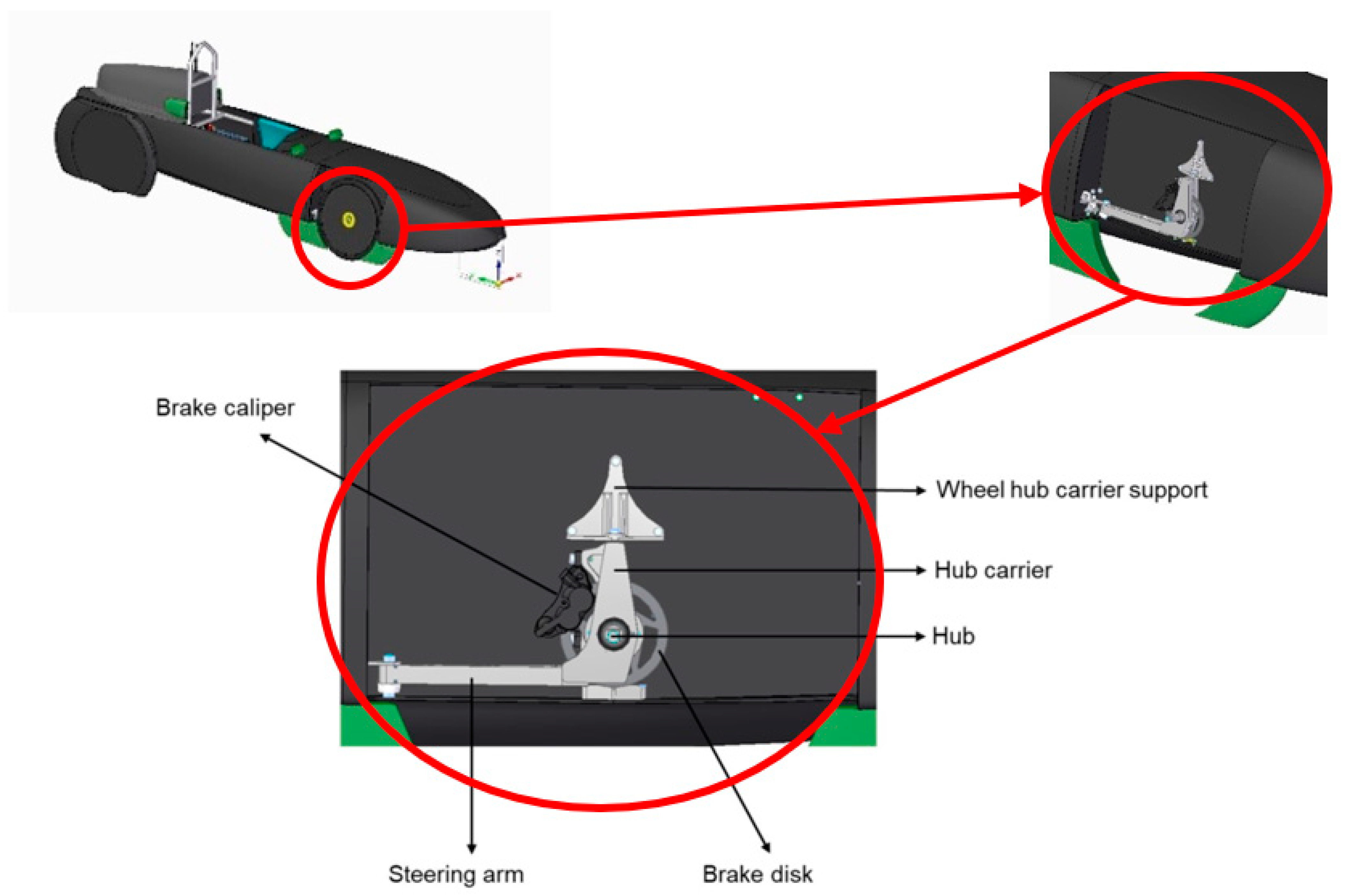
The wheel hub carrier bracket of the prototype that was used in this work, in order to assess the influence of using basalt fibers on this component, was previously constructed with aluminum 7075-T6 from KMS – Technical Material, Lda from Portugal [23]. The wheel hub carrier bracket is an important component in the system because the pilot transmits the movement from the hand steering to the wheels thrown in this component. The physical and mechanical properties of the aluminum are presented in Table 1.
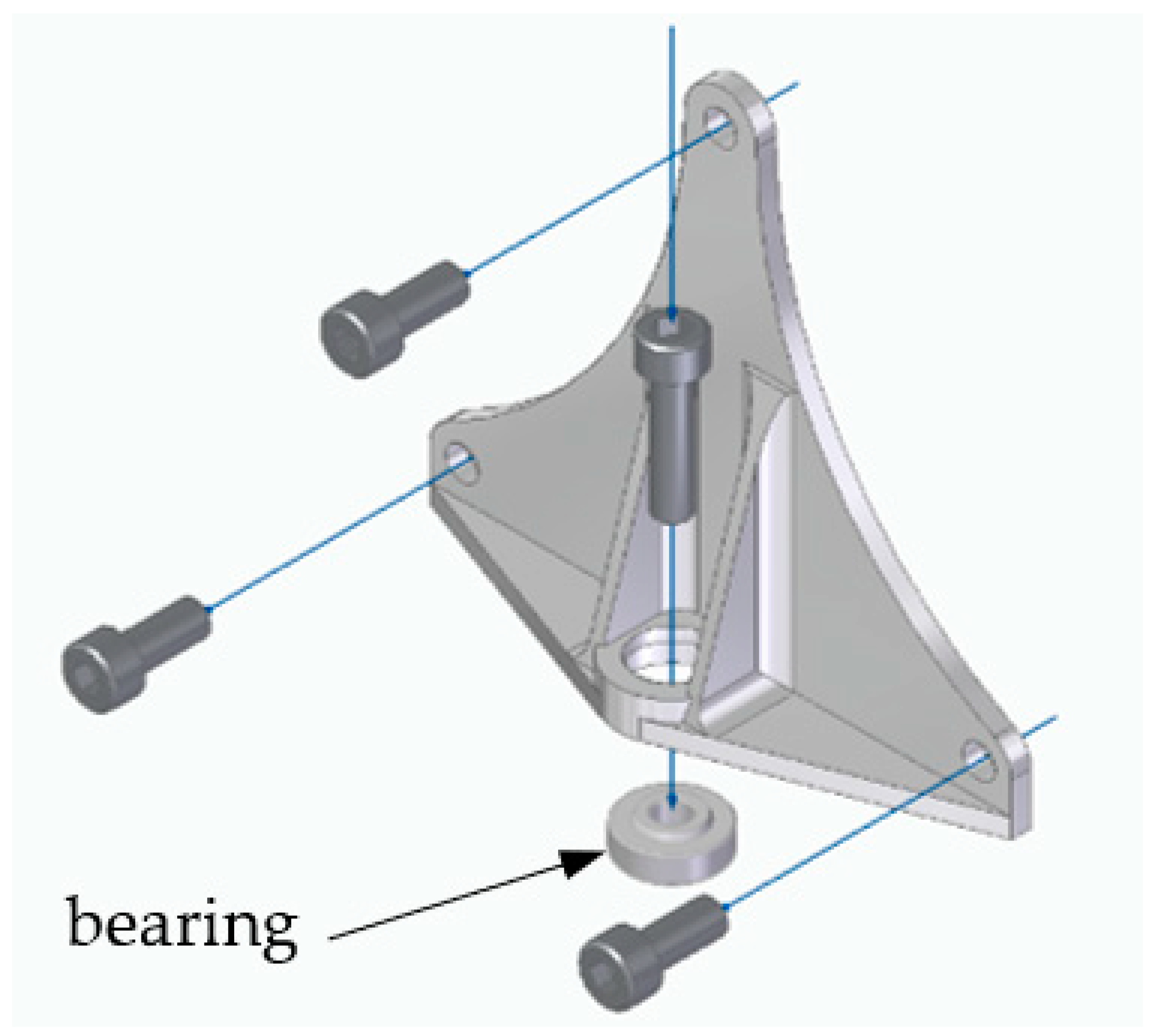
This element is present in both sides of the prototype and is part of its steering system. Its main role is to attach the steering system to the vertical structure of the prototype (Figure 1), through three M5 bolts while allowing wheel rotation (Figure 2). Its location on the prototype is schemed in Figure 1. The rotation movement is achieved by using a radial spherical plain bearing GE5E from SKF® from Portugal [24] placed on the central bearing housing in the component’s bottom part (Figure 2). The connection between the bracket and the remaining part of the steering system is also fixed on the central hole by an M5 bolt placed vertically.
2.2. Applied Loads
The wheel hub carrier bracket part is a vital component of the prototype. Due to the need to ensure precise alignment of the entire steering system, and, since this prototype does not have a suspension, the component is responsible for supporting all the loads from the prototype system plus the pilot weight, as well as possible impacts that may arise from irregularities on the racetrack. Therefore, it is necessary to be aware about the loads that are applied.
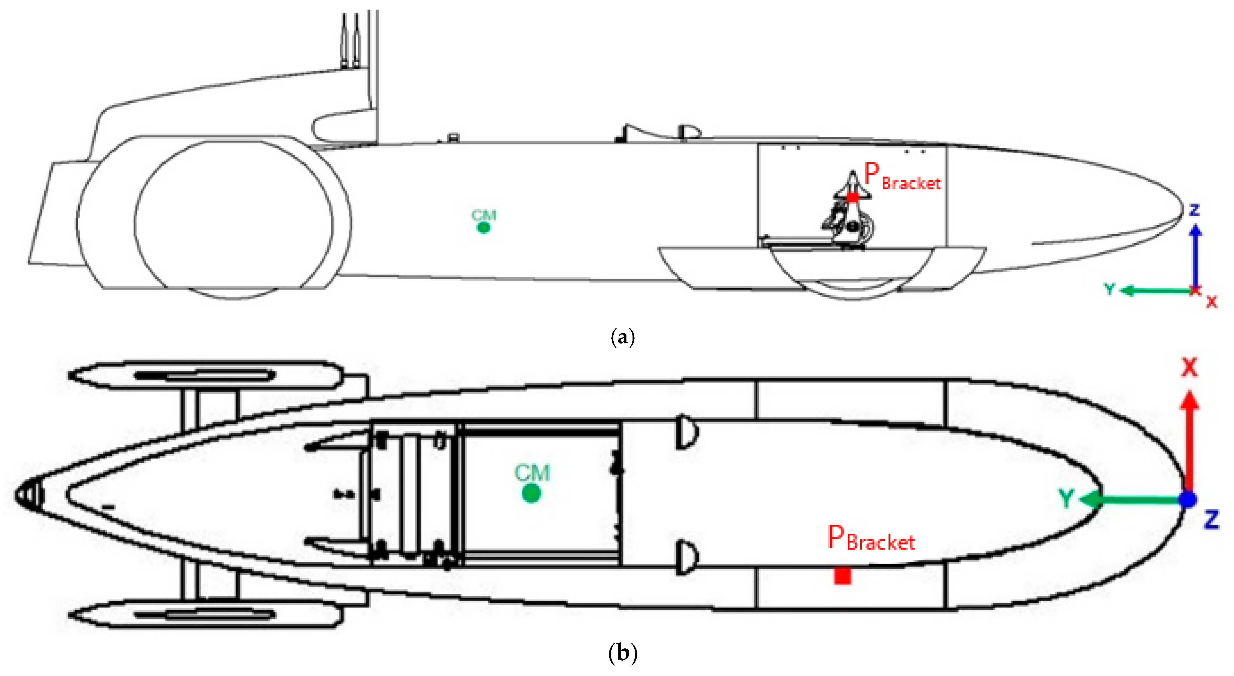
Using Solid Edge ST10 software from Siemens [25], the prototype was designed, and the weight of 110 kg was obtained. Subsequently, it was possible to estimate the center of mass (CM) of the prototype system plus the pilot, and also the position of the contact point between the bracket and the remaining steering system (PBracket) (Figure 3).
Once the coordinates of the CM and PBracket were obtained, they are given by Equations (1) and (2).
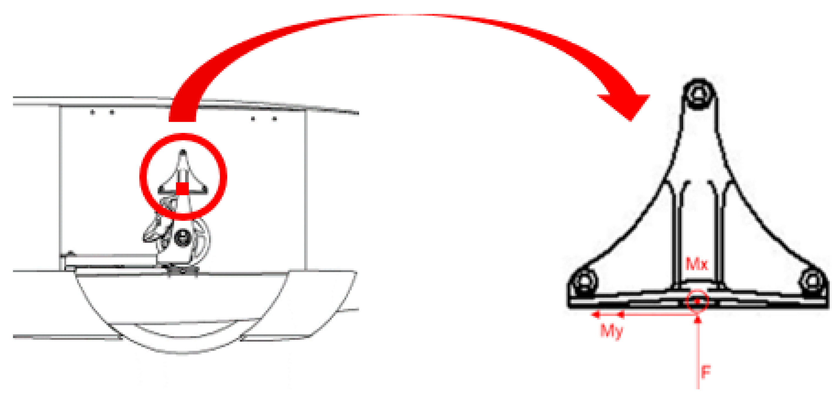
From which was possible to understand that 47% of the weight is applied in the front shaft of the prototype. It was also implemented as a safety coefficient using the Pugsley method [26], consisting of using several empirical data such as the material quality or the economic impact if the failure would occur, which generates an oversize loading. A safety coefficient of 2.73 was chosen and the applied load to each wheel of the front shaft was obtained by Equation (3).
where is the gravitational acceleration and is the safety coefficient.
The obtained load of 692.3 N was aimed to be applied in the CM of the prototype and should be transferred to the contact point. Therefore, the distance between CM and PBracket was obtained by Equation (4) and the moment of the in the contact point was obtained by Equation (5).
2.3. Finite Element Method
For the implementation of a new bracket fabricated with polymer composite material reinforced with basalt fibers (BFRP), it was necessary to proceed with the design of a new component with the same geometric constraints and equivalent mechanical characteristics than the original one, which is, however, lighter and effortless to fabricate. Therefore, a finite element method (FEM) analysis was performed using the commercial software Siemens NX12, on the original component to obtain the deformations and stresses that this component was subjected.
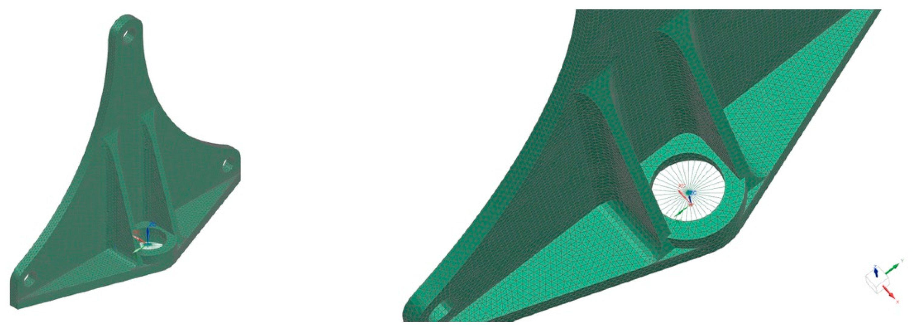
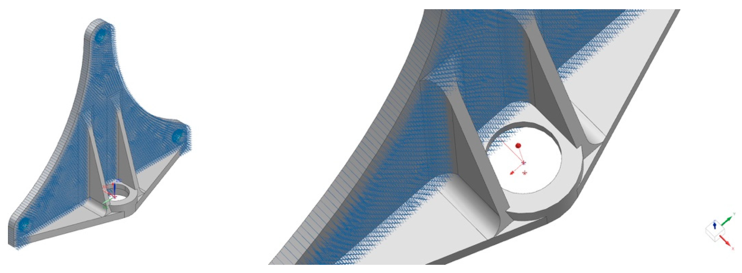
For the FEM of the aluminum component, three-dimensional solid elements were used, and the mechanical properties (Table 1) associated with them were defined as the PSOLID type, once the considered material is a solid. The element mesh was performed with solid elements 3D CTETRA with four nodes because they adapt better to complex geometries. One mm was chosen for the element dimensions so that they would be fitted within the curvature radii. This way, 76,517 elements with 18,851 nodes were used. In addition, RBE3 connector elements were used in the central bearing housing because they are able to make the correct distribution of the applied loads and do not add extra weight or stiffness to the structure. Figure 5 shows the FEM of the original aluminum wheel hub carrier bracket, where it is shown that the connector elements are applied in the central housing.
This way, a SOL101 Linear Statics global constraints analysis was undertaken due to the expected linear elastic behavior with small deformations. Since the back-face of the component is leaning against the structure of the prototype, only the constraint according axis xx was considered fixed (Figure 6).
2.4. Finite Element Results
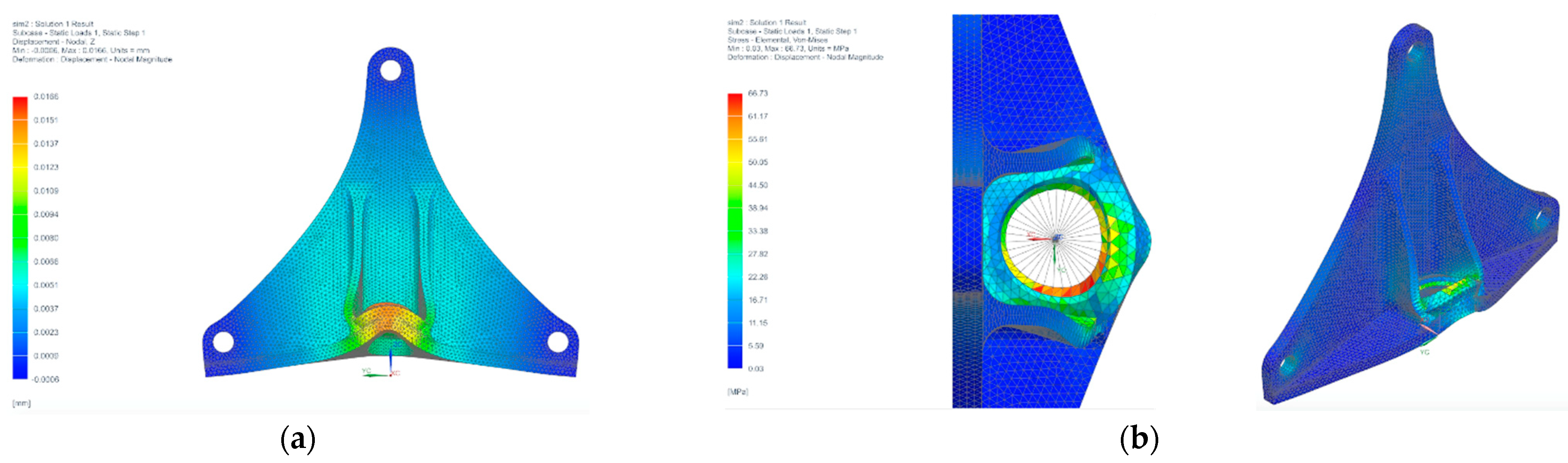
Deformations and stresses in the original aluminum component was obtained to understand how it would affect the performance. Therefore, Figure 7 shows the FEM analysis results for the original aluminum wheel hub carrier bracket subjected to the loads present in Table 2.
Therefore, the maximum value for the displacement verified from Figure 7a appears in the central area of the component where the radial bearing is located (central bearing housing), presenting a maximum value of 0.017 mm in the zz positive direction. It is also verified from Figure 7b as the existence of stress concentration on the same location as the maximum deformation, i.e., presenting a maximum stress of 66.73 MPa.
3. Production of the BFRP Component
3.1. Materials and Properties
The basalt fibers BAS 220.1270P used in this work were supplied by Basaltex NV, and the epoxy resin SR1500 with SD2505 hardener, with the ratio of 100:33 wt.%, according to the Sicomin supplier. The physical and mechanical properties of the starting materials are present in Table 3.
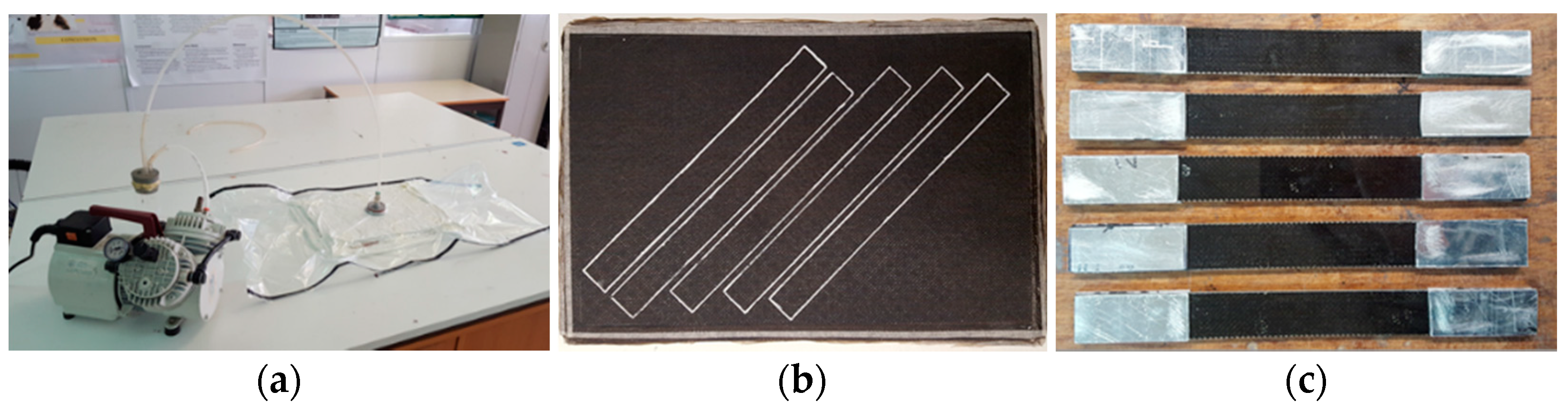
The ASTM D3039 [27] standard was used to obtain the tensile properties and the ASTM D3518 [28] standard was used to obtain the shear properties of the BFRP composite. To do so, two plates with [0/90]6s lay-up and 340 × 230 mm were produced by hand-lay-up with 700 mPa of vacuum bagging for 24 h at an ambient temperature (Figure 8a). After that, five specimens with 250 × 25 mm of each lay-up, [0/90] and [±45] (Figure 8b) were cut with a circular diamond saw. In order to be tested, aluminum tabs with 60 × 25 × 2 mm were glued with DP490 from 3M® supplier and cured under pressure for 24 h after sand polishing (Figure 8c). Specimens were then tested in an Instron 3369 testing machine with 50 kN of the load cell and a Bluehill software under 2 mm/min of displacement control and the obtained physical and mechanical properties are shown in Table 4. The density of the BFRP composite was also determined.
3.2. Geometry Optimization
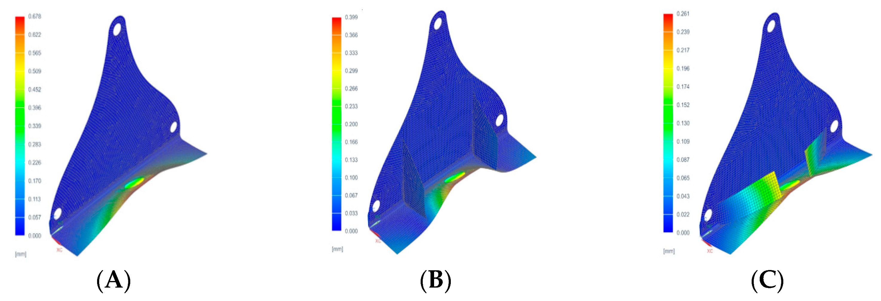
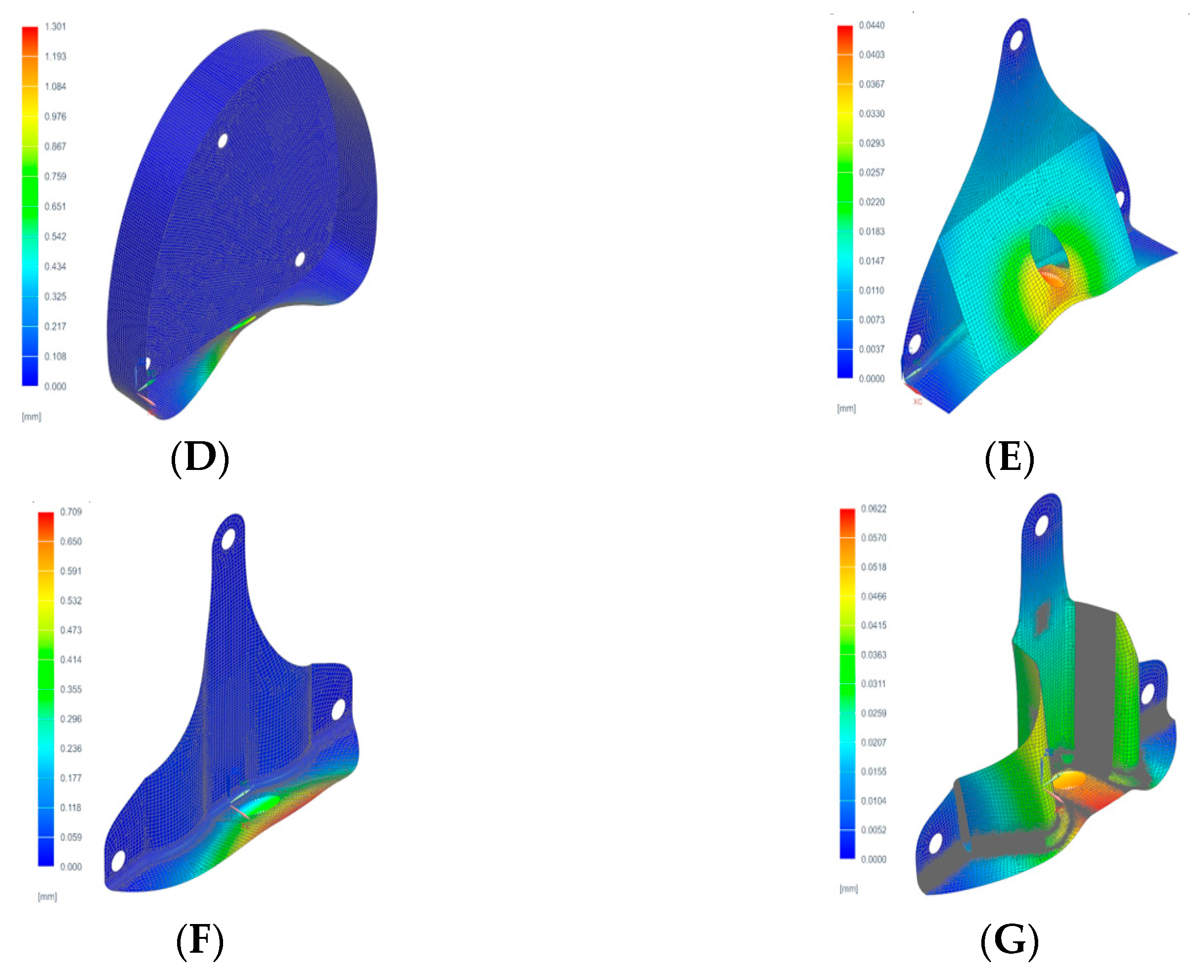
Taking into consideration the information acquired regarding the geometric constraints and the original component’s behavior, several new possibilities for a new component were examined. The FEM analyses performed, using a preliminary and basic stacking sequence, were used to assess the behavior of the designed geometries.
A [0/90] lay-up with 0.2 mm of lamina thickness was used to simulate the composite material component. It was considered a 2D CQUAD4 mesh with four nodes and 1 mm of dimension, since the thickness is smaller than the other dimensions. This way, a SOL101 Linear Statics analysis was conducted by taking into consideration all the information regarding the geometric constraints and the original component’s behavior and also the mechanical properties of the BFRP composite. Several new possibilities for a new component were studied and various geometries were analyzed, as shown in Figure 9. Also Table 5 presents the weight, the maximum deformation, and the Von-Mises stresses that occur in the aluminum original part and in the alternative ones produced by BFRP composites.
Geometry A, as the starting point of this study, was considered due to be simple and easy to be manufactured by the hand-lay-up composite’s technique. However, a high deformation compared to the original bracket, occurred in the base of the component.
Geometry B, C, and E were considered based on geometry A, with the introduction of two vertical ribs, leading to a reduction on the deformation, which, however, led to a new problem, i.e., the difficulty of hand-lay-up construction and the possibility of the reinforcements to be poorly joined to the structure in the manufacturing process, resulting in the component’s failure.
Geometry D was created with the idea of a component produced with no glued parts, but, quickly, it was concluded that its weight was very high, and also the elevated deformation was not solved.
In geometry F, it was decided that the component should be produced in a single step. Therefore, for this purpose, small reinforcements occur on the vertical face, in order to diminish its deformations and increase its stiffness, but, after further analyses, the deformation observed was still high.
Taking into account the positive results obtained in the previous iteration, some changes were made, and geometry G was obtained. It showed a decrease in weight and improved characteristics regarding the deformation and stresses when compared to the original one.
3.3. Lay-Up Optimization
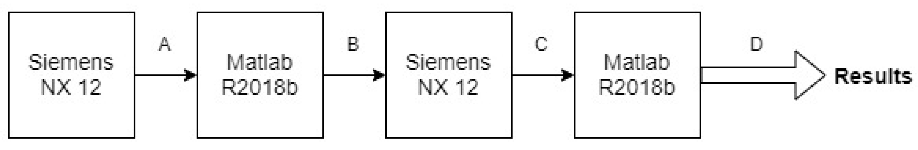
An optimization process of the lay-up regarding the number of layers and ply-stacking was performed. MATLAB® R2018b software was used to develop a model to obtain the best ply-stacking sequence (number of layers and orientation) for the chosen geometry G. The model worked as an interaction with the finite element solver, associated with a commercial software called Nastran. The optimization model works together with FEM to evaluate the possible ply-stacking sequence, as shown in Figure 10. MATLAB reads the variables from a text file (*.dat) generated by the Siemens NX 12 (Figure 10A). The file is read, and the location related to the stacking sequence is found, and then changed (Figure 10B). The file is saved, and the finite element solver is initialized (Figure 10C). Once the simulation is over, the MATLAB program reads the output file generated by Siemens NX 12 (*.f06), and locates the required data, which is the weight and the maximum deformation verified in the structure (Figure 10D).
In order to simplify the optimization process and avoid long processing times, it was initially defined that the laminated component was symmetric with 10, 12, 14, or 16 layers and restricted to 0/90 and ±45 fiber orientation because of the woven fabric used. The minimum of 10-layers were defined because of the need of bracket material near the central housing for the bearing and the maximum of 16-layers was defined due to the requirement of presenting lower height than the original component.
The optimization is complete when all the lay-up sequences have been analyzed. The optimization classifies the lay-up from lower deformation and smaller weight to maximum ones.
Analyzing the results obtained and comparing the deformations verified with the weight obtained for each stacking sequence, it is possible to conclude that most advantages lay-up presents the 10 layers of stacking with the [(0/90)3/(−45/+45)/(0/90)]s. In this way, the obtained lay-up was used to produce the BFRP component, and the mechanical properties were analyzed experimentally and via FEM simulations.
3.4. Manufacture of BFRP Component
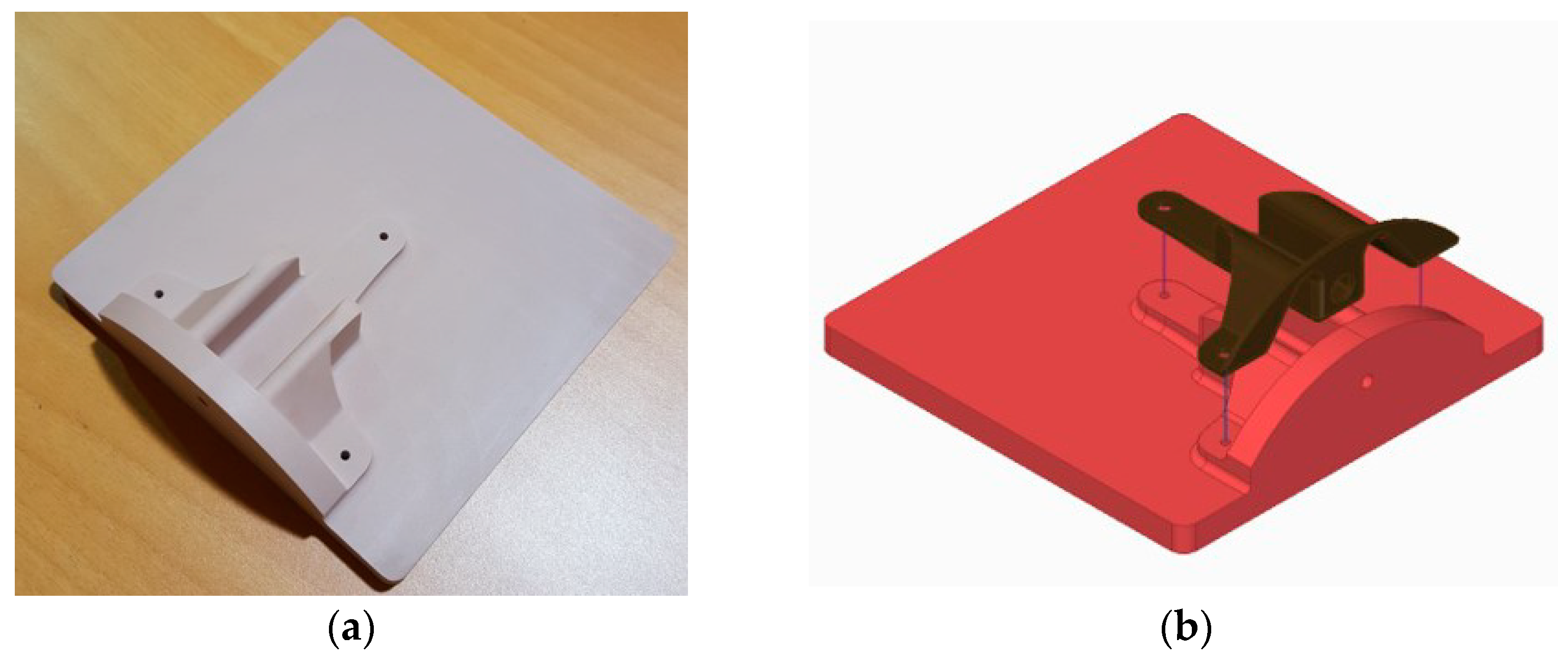
A mold of polyurethane was fabricated by a computer numerical control (CNC) machine from a 160 × 160 × 50 mm SikaBlock M 700 by Sika® in order to produce the BFRP composite (Figure 11a) after the design with the Siemens NX12 software (Figure 11b).
The sealing HP2002 from MARBOCOTE was applied on the surface of the mold to impregnate it and sealed, according to the supplier instructions. After that, a HP7 demolding agent, also from MARBOCOTE was applied. Thus, the final part could easily be removed.
Two parts with the same mold were fabricated with hand-lay-up by a vacuum bag. The first one, component A (Figure 12a), was produced with 10 basalt fiber layers with 150 × 150 mm. The second part, component B (Figure 12b), was fabricated with 10 basalt fiber layers with the geometry obtained by Siemens NX 12, i.e., the software calculated the 2D geometry from a 3D model of the component. For both cases, one layer of perforated Teflon® film and two layers of breather in the lay-up were also used.
The component A was produced by hand-lay-up during 24 h with a vacuum bag with 800 mPa. The component B was produced in two steps. Five layers by hand-lay-up for 24 h plus five other layers again by hand-lay-up for another 24 h. In both steps, the vacuum bag had 800 mPa.
In both parts, a metallic ring was inserted in the middle of the stacking sequence in the central bearing housing in order to work as strengthening. Gebhardt [29] and Akbarpour [30] showed that the specimens with inserts show up to 60% strength improvement in pin-loaded tests. Figure 12b shows component B with the ring waiting for the second step of manufacture.
In both components, a finishing was undertaken to eliminate all fiber in excess. It was also needed to drill holes with 5 mm of diameter and machining the housing for the plain bearing with 9.5 mm. The entire edge was finished with a 320-weight sandpaper in order to obtain a smooth surface.
3.5. Experimental Tests
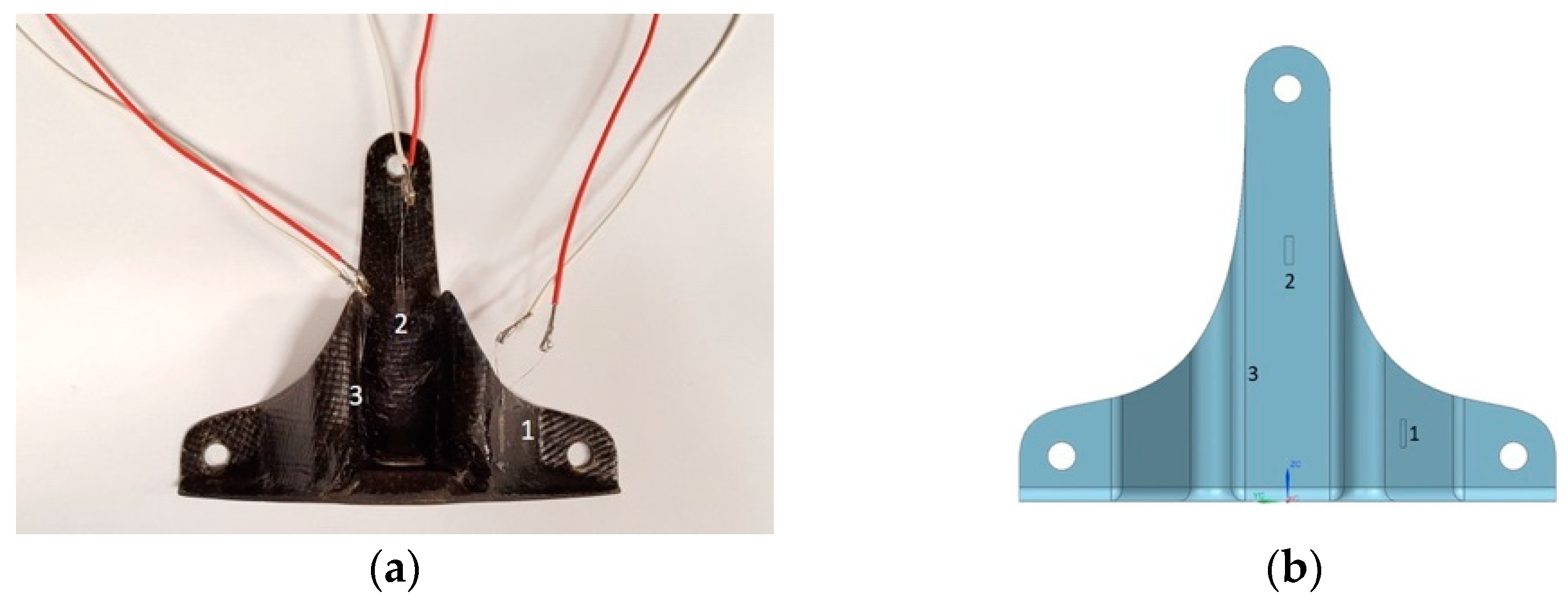
Since component B seems to have fewer imperfections than component A visually, it was instrumented with three strain gauges, with 120 Ω and a gauge factor of 2.13, in the three positions shown in Figure 13. These positions were chosen due to the deformations and stresses observed from the FEM analysis.
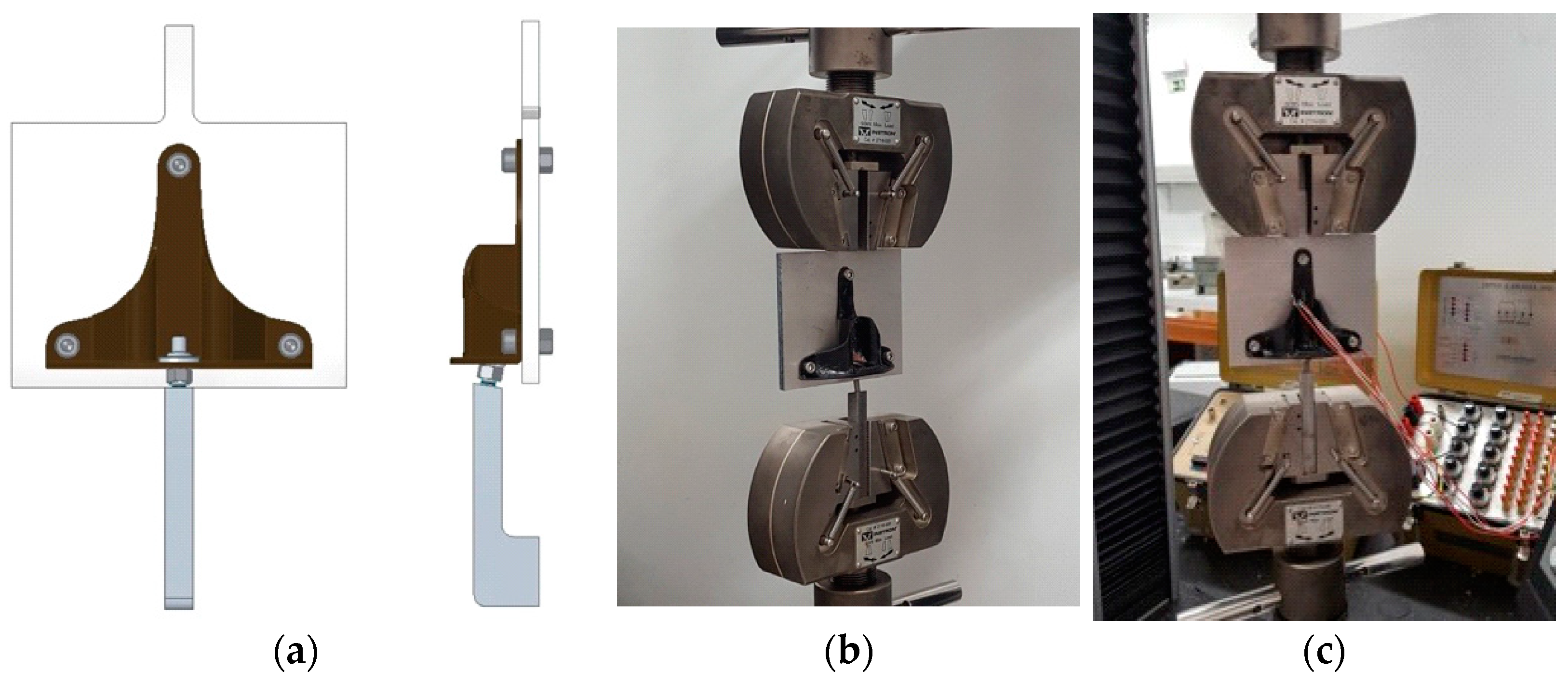
Since the universal testing machines execute mainly tension/compression movements, it was necessary to design and machine an experimental setup fixture in order to carry out the experimental test to reproduce the real conditions including the camber angle of 10° (Figure 14a). The experimental tests were performed in a universal testing machine—Instron 5566 with a 10 kN load cell (Figure 14b,c).
The developed setup includes an aluminium top plate where the whell hub carrier bracket is held with three screws simulating the structure of the prototype and a stell L shape bottom structure simulating the camber angle bolted with a M5 bolt to the hub.
Component A was subjected to a continuous load with displacement control of 2 mm/min until component’s failure. Component B was tested mannualy by steps of loads with increases of 0.5 kN until the component fails, in order to obtain the strains.
3.6. FEM of BFRP Component
A FEM analysis was undertaken into the BFRP component with the properties obtained previously from the experimental tests of the specimens from Table 4 where each layer had 0.18 mm of thickness and with the lay-up obtained by the optimization process.
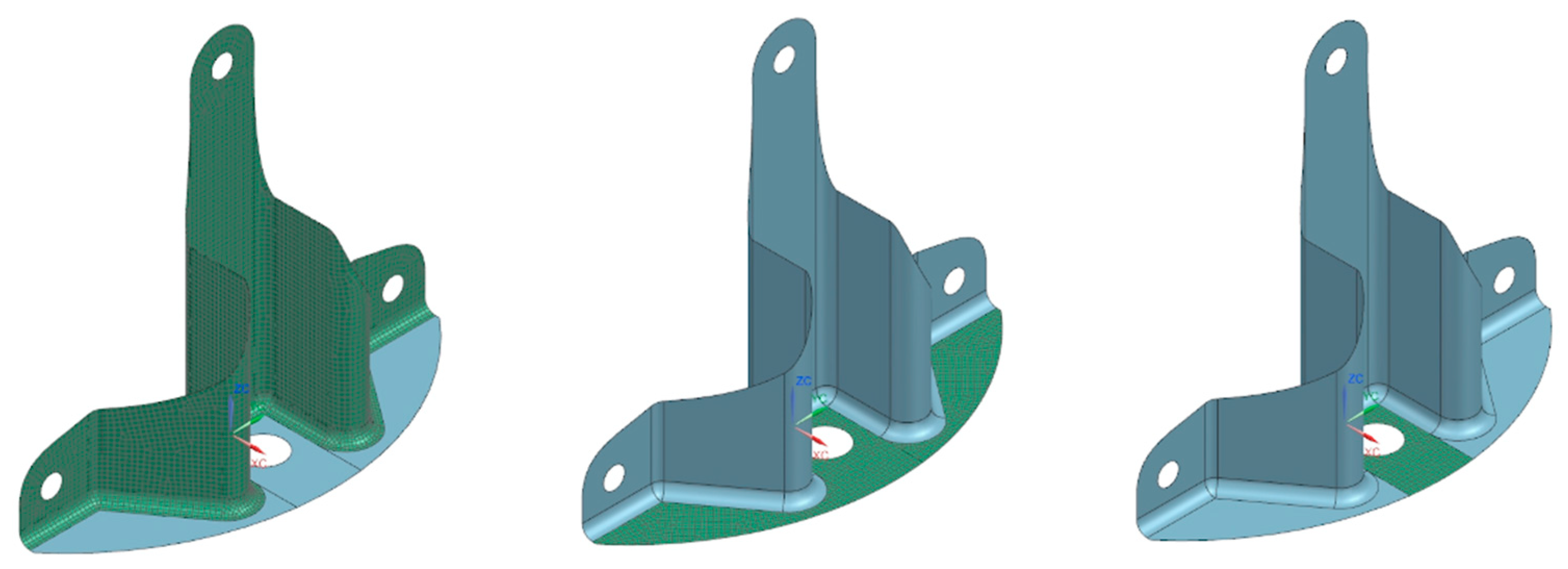
To develop the BFRP wheel hub carrier bracket by FEM, the mesh was divided into three different zones, represented by green in Figure 15 and linked using Stitch Edge command from Siemens NX software. It was used as a 2D CQUAD4 quadrangular mesh with 6397 elements and 6681 nodes and a SOL101 Linear Statics analysis was also conducted.
In order to estimate the critical load that the component can withstand for a given stacking, a failure criterion of the maximum deformation was chosen. This criterion considers that the laminate reaches its breakage when the strain in a lamina exceeds a pre-defined interval, either at compression or tension. This criterion was implemented in the Siemens NX in order to obtain the maximum load before breakage of the BFRP component.
4. Results and Discussion
In order to assess how the new solution had advantages or disadvantages over the existing component, a comparison of several parameters (weight, strain, stress, and deformation) was made to assess the applicability of the new BFRP composite component.
4.1. Deformations
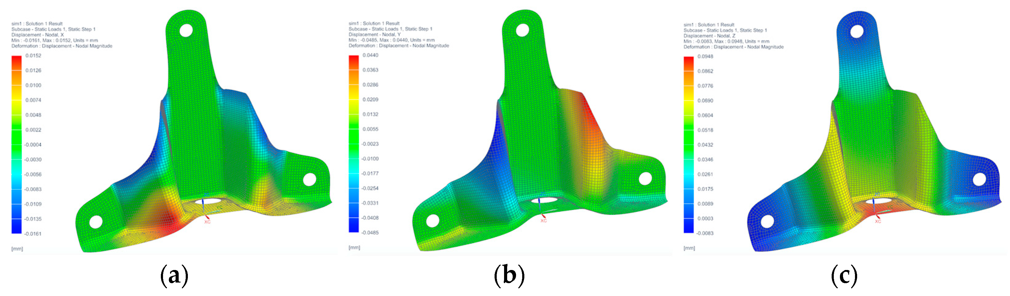
Deformation results obtained from the FEM are shown in Figure 16 along the three axes (x, y, and z). From the analysis of this figure, it is possible to verify that the higher deformation occurs in the zz axis (Figure 16c). This is expected as the largest applied load was, according to the vertical axis. The 0.095 mm deformation occurs in the central bearing housing in the component’s bottom part for a maximum load of 4.770 kN.
The deformation achieved on the yy axis (Figure 16b) were also considerable mainly due to the vertical load, resulting in a maximum value of 0.044 mm, contrary to the deformation verified according to the xx axis, presenting a maximum value of 0.015 mm. This is due to the rotational moments applied in the component, resulting in a higher deformation in the left side of the component (Figure 16a).
4.2. Stresses
Contrary to what is verified in the isotropic materials, orthotropic materials are a combination of layers. Therefore, the analysis is affected through the stresses that occur in each layer and not in the material as a whole.
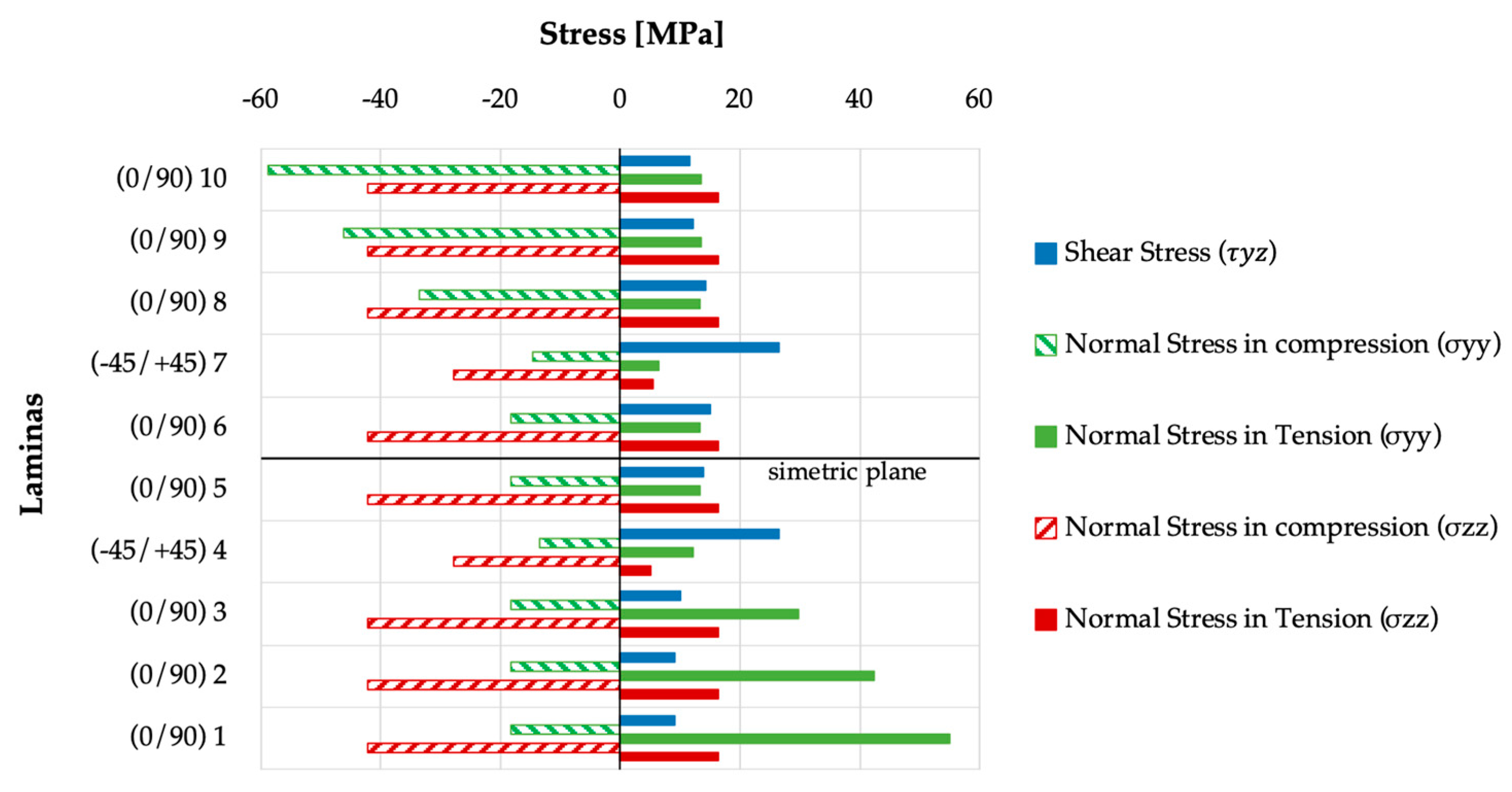
Therefore, the stresses in the bottom hole of the component were analyzed and verified in each of the 10 layers. Figure 17 present the maximum values of the normal and shear stresses that occur for the applied loads in the BFRP component.
In Figure 17, the laminas numbered from 1 to 10 correspond to the stacking obtained from the optimization process from which the component was manufactured [(0/90)3/(−45/+45)/(0/90)]s. Analyzing the normal stresses by σzz is understandable that there is a great contribution of the 0/90 plies (1, 2, 3, 5, 6, 8, 9, and 10), contrary to the ±45 laminas (4 and 7), being verified as a reduction of 66.12% in tension and 33.92% in the compression.
From the σyy stress results, it is possible to observe a typical characteristic behavior of the materials constituted by layers when these are subjected to flexion, i.e., laminas located above the symmetric plane are subject to tension while the laminas below are in compression, or vice versa, depending on the loading direction. In the situation of shear stresses that could occur in the BFRP component, the shear stresses τyz with ±45 laminas are responsible for withstanding most of the stresses with an increase of approximately 50% when compared to the 0/90 laminas.
4.3. Strains
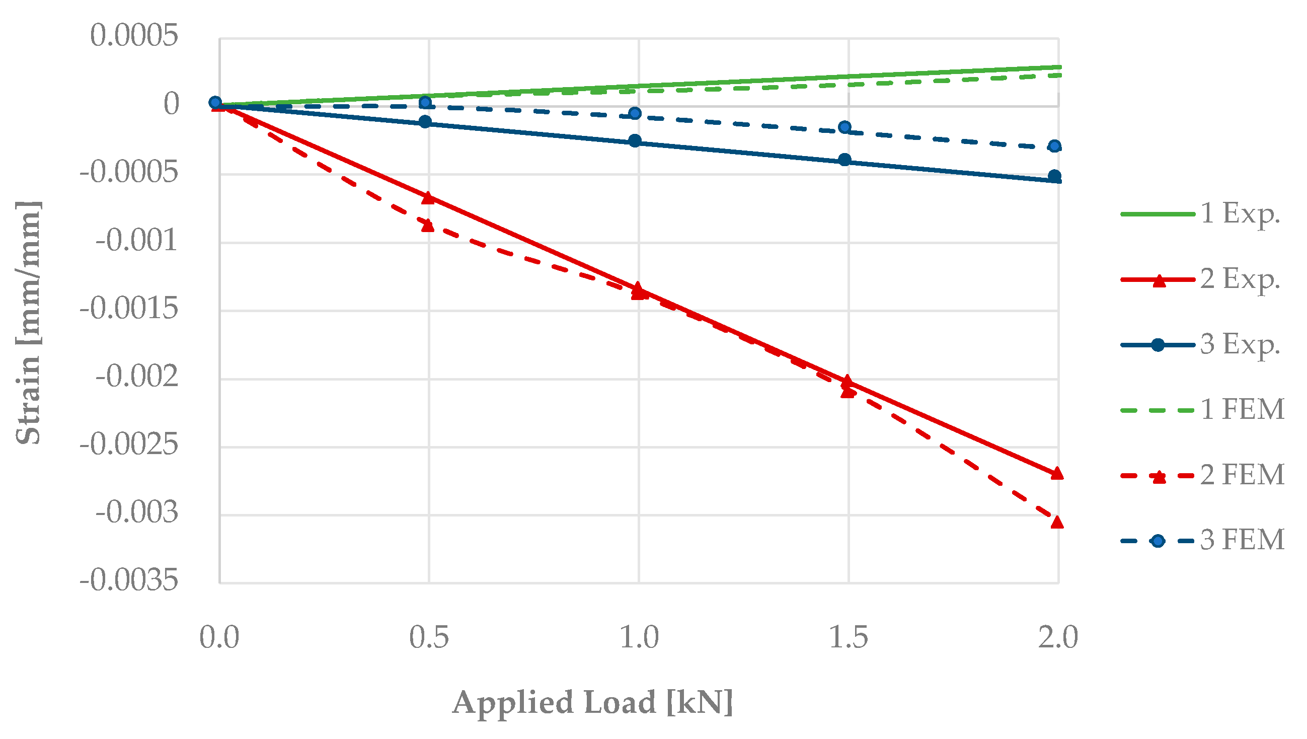
Figure 18 displays the strain results from the experimental tests (Exp.), with continuous lines, and from the finite element method (FEM) with dashed lines. The strains were obtained from the three strain gauges shown previously in Figure 13b.
From Figure 18a, it is evident that the strain results are consistent between the FEM and the experimental tests, presenting a linear pattern except for the strain gauge 2, showing a non-linear outline on the experimental results. Nevertheless, this non-linearity strain gauge 2 shows the lower deviations (Table 6). Differently, strain gauge 3 presents the higher deviation from experimental and FEM. This deviation occurs in the strain gauge that is located in the non-planar face, i.e., in the curved zone of the component. This non-planar face originates as misaligned on the fiber’s orientation that occurs because of the twisting of the woven fabric of basalt fiber used in the BFRP during the manufacturing process.
4.4. Failure
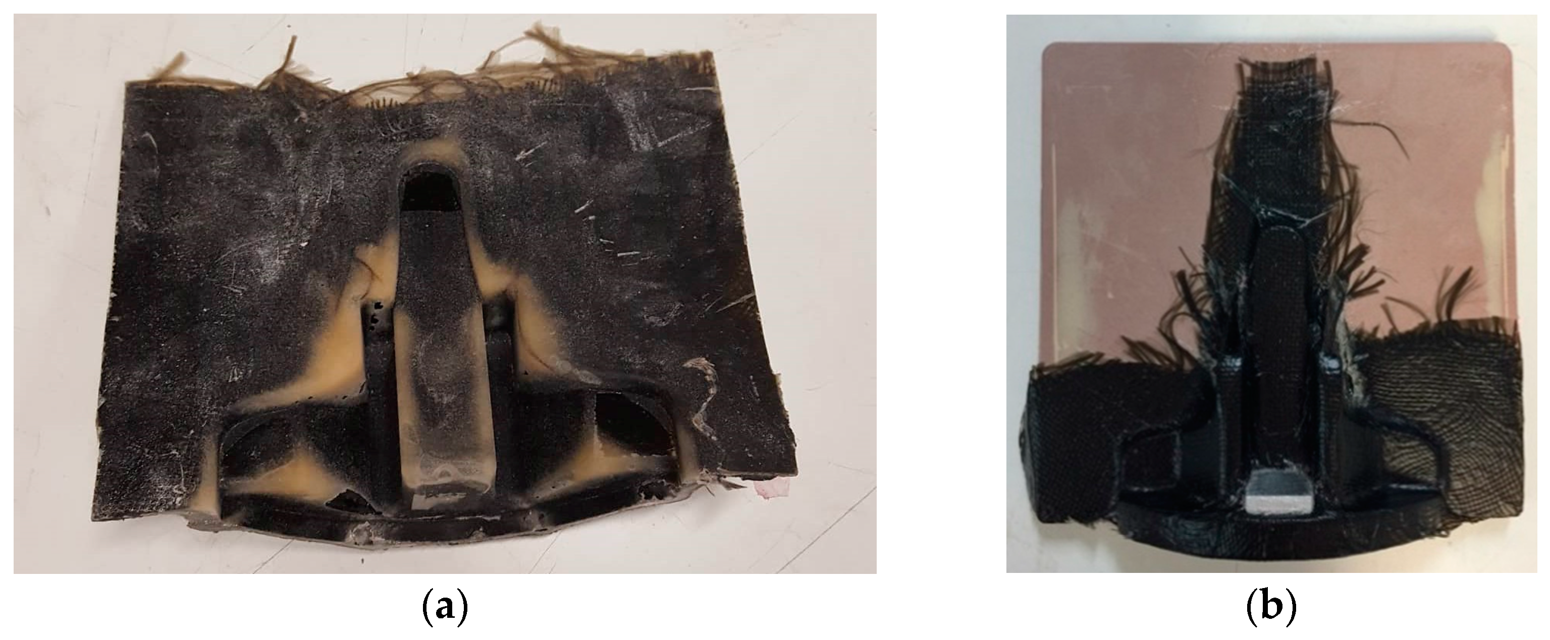
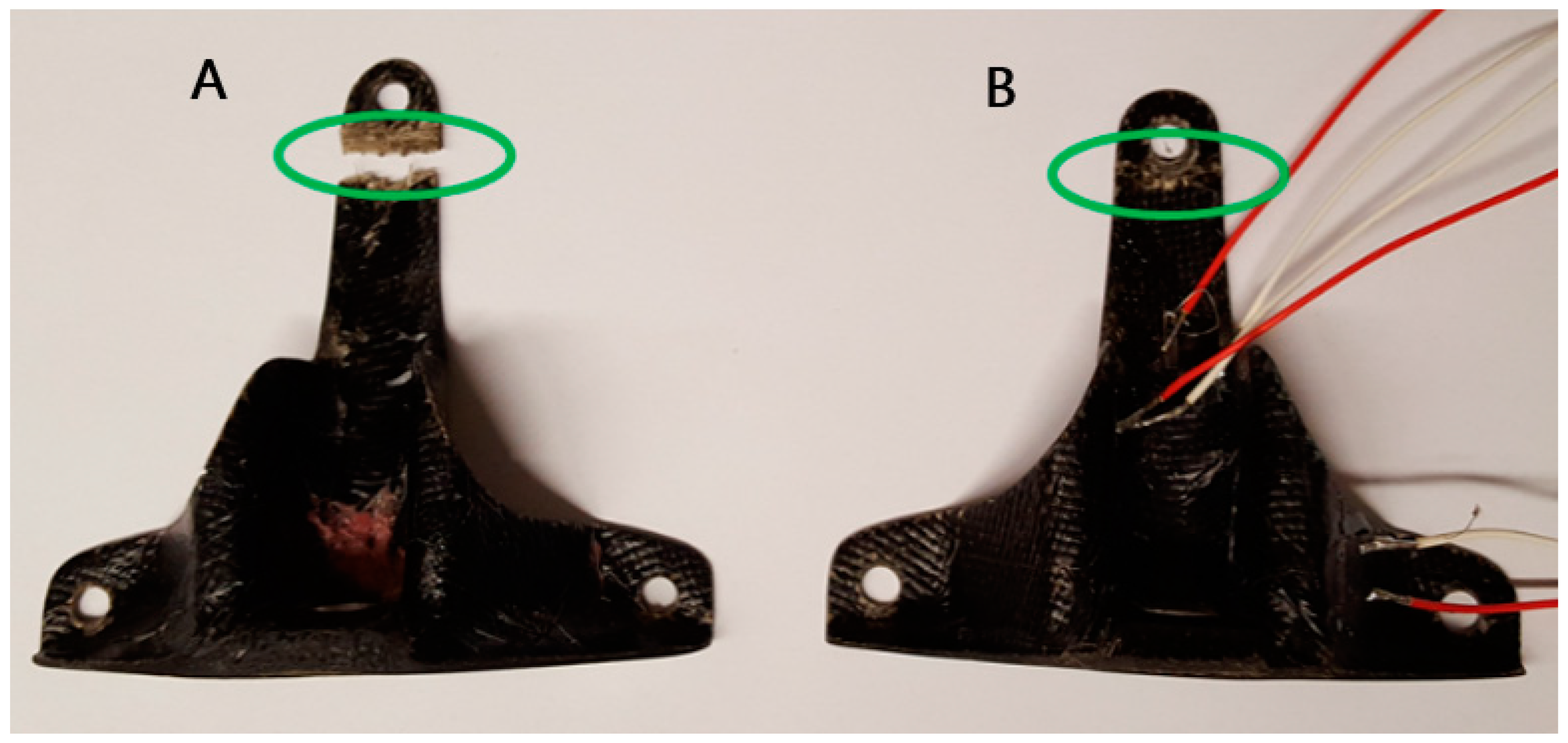
From the maximum deformation failure criterion specified from the FEM analysis, a value of 4.770 kN was found. It should be noticed that, experimentally, component A reached a breakage value of 3.338 kN, 30% lower, and component B only attained 2.365 kN, 50% less. Bring to mind that component A was produced in one step only, including more difficulties in the lay-up process due to the amount of fabric. In addition, from Figure 12a, it is clear that this component exhibits a higher amount of resin than component B. Component B is more pleasant visually (Figure 12b) and the lay-up process was easier due to the two-steps production. Somehow, it may have introduced defects inducing delamination.
Figure 19 shows the two final BFRP components, A and B, tested up to failure, which occurred in the same place, near the top hole.
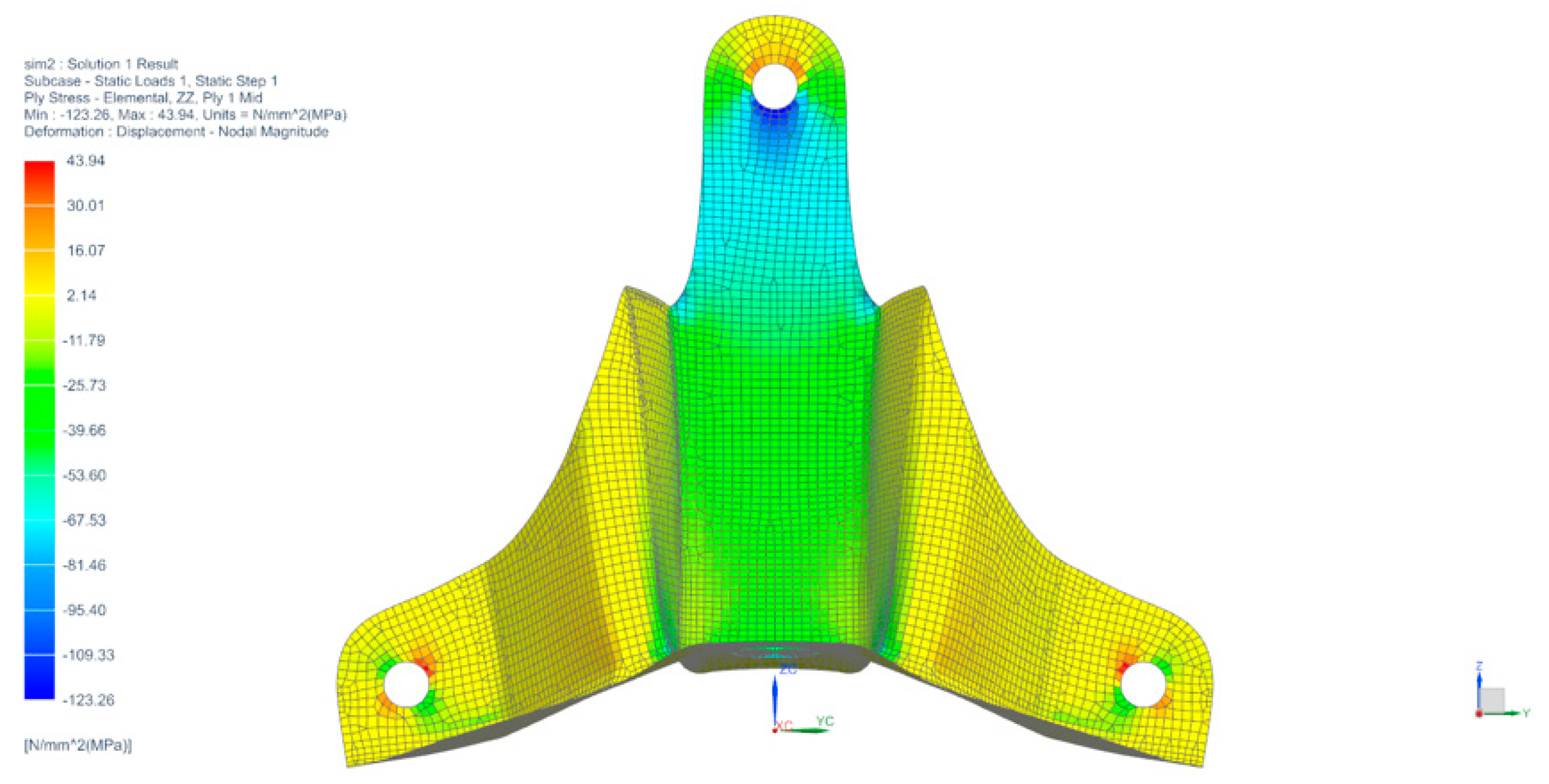
According to FEM analysis, Figure 20 shows the stresses that arise on the component with a vertical load of 2.0 kN and it is clear that a stress concentration appears in the top hole in the below side, such as the experimental ones, exhibiting a maximum of 120 MPa in compression. It should be concluded that the main cause of failure would be the stress concentrations near the top hole.
4.5. Comparative Analysis between the Original and the New Component
Figure 21 shows the BFRP alternative component and the original one made by aluminum, where the geometric differences are clearly evident, mainly in the thickness. Additionally, Figure 22 shows the BFRP and the original component mounted in the prototype, where it is visible as the same constraints by bolts.
Table 7 presents the main physical and mechanical properties for the two components as an original and alternative one.
Considering the results in Table 7, it is verified that the weight of the alternative component is quite inferior, resulting in a 45% reduction in the total weight of these components in the prototype. Lower stresses were also verified in the component produced by BFRP composite material, which may contribute to increase its lifetime. The maximum deformation corresponds to the vertical direction (zz), which is higher in the alternative component, since the capacity of fiber reinforced composites to resist loads is smaller when compared with aluminum due to a higher Young modulus. However, the discrepancy verified is quite small and does not produce negative consequences in the entire steering system. The ideal situation would be to reduce deformation. However, the advantages added by the new component largely compensate for the disadvantages that may have been added.
5. Conclusions
In this paper, the assessment of BFRP composites to replace an aluminum component, i.e., a bracket from the steering system of an electrical prototype, was presented. The original aluminum component was studied in terms of weight, stress, and deformations using FEM analysis. A geometry and a lay-up optimization were undertaken in order to evaluate the production of a composite material to use in the prototype’s component. BFRP composite components were then manufactured and tested experimentally and by FEM simulations. It is possible to state that the hypothesis of the use of basalt fiber reinforced composites in parts as replacement of others made in aluminum 7075-T6, which is a viable alternative. Due to all variables present in this type of design, which are difficult to have a clear control, such as track irregularities, accidental fall of the prototype during handling, or imperfections during the manufacturing process, the entire study took into account an oversizing of the applied loading. In this sense, the obtained results are conservative and very satisfactory.
Author Contributions
Conceptualization, R.M.-M., D.R. and L.R. Production, R.M.-M. and D.R. Experimental tests, D.R. and L.R. FEM analysis, D.R. Writing—original draft preparation, R.M.-M. Writing—review, R.M.-M., D.R. and L.R. Writing—editing, R.M.-M. Supervision, R.M.-M. and L.R. All authors have read and agreed to the published version of the manuscript.
Funding
This research was funded by FCT, through IDMEC, under LAETA, Project UIDB/50022/2020.
Acknowledgments
The authors would like to acknowledge the PSEM project.
Conflicts of Interest
The authors declare no conflict of interest. The funders had no role in the design of the study, in the collection, analyses, or interpretation of data, in the writing of the manuscript, or in the decision to publish the results.
References
- Clyne, T.W.; Hull, D. An Introduction to Composite Materials, 3rd ed.; Cambridge University Press: Cambridge, UK, 2019. [Google Scholar]
- Barbero, E.J. Introduction to Composite Materials Design; CRC Press: Boca Raton, FL, USA, 2017. [Google Scholar]
- Friedrich, K.; Almajid, A.A. Manufacturing aspects of advanced polymer composites for automotive applications. Appl. Compos. Mater. 2013, 20, 107–128. [Google Scholar] [CrossRef]
- Palmer, R.J. History of Composites in Aeronautics; Wiley Encyclopedia of Composites, John Wiley & Sons, Inc.: Hoboken, NJ, USA, 2012. [Google Scholar]
- Szuladziński, G. Performance of composites versus metals under extreme loading. Int. J. Prot. Struct. 2017, 8, 86–108. [Google Scholar] [CrossRef]
- Goubalt, P.; Mayes, S. Comparative Analysis of Metal and Composite Materials for the Primary Structures of a Patrol Craft. Nav. Eng. J. 1996, 108, 387–397. [Google Scholar] [CrossRef]
- Bunsell, A.R. Handbook of Properties of Textile and Technical Fibres, 2nd ed.; Woodhead Publishing: Cambridge, UK, 2018. [Google Scholar]
- Gangil, B.; Ranakoti, L.; Verma, S.; Singh, T.; Kumar, S. Chapter 1: Natural and Synthetic Fibers for Hybrid Composites. In Hybrid Fiber Composites: Materials, Manufacturing, Process Engineering; Khan, A., Rangappa, S.M., Jawaid, M., Siengchin, S., Asiri, A.M., Eds.; Wiley-VCH Verlag GmbH & Co: Hoboken, NJ, USA, 2020. [Google Scholar]
- Begum, S.; Fawzia, S.; Hashmi, M.S.J. Polymer matrix composite with natural and synthetic fibres. Adv. Mater. Process. Technol. 2020, 6, 547–564. [Google Scholar] [CrossRef]
- Lopresto, V.; Leone, C.; De Iorio, I. Mechanical characterisation of basalt fiber reinforced plastic. Compos. Part B Eng. 2011, 42, 717–723. [Google Scholar] [CrossRef]
- Dhand, V.; Mittal, G.; Rhee, K.Y.; Park, S.-J.; Hui, D. A short review on basalt fiber reinforced polymer composites. Compos. Part B Eng. 2014, 12, 166–180. [Google Scholar] [CrossRef]
- Sathishkumar, T.P.; Satheeshkumar, S.; Naveen, J. Glass fiber-reinforced polymer composites—A review. J. Reinf. Plast. Compos. 2014, 33, 1258–1275. [Google Scholar] [CrossRef]
- Singha, K. A short review on basalt fiber. Int. J. Text. Sci. 2012, 1, 19–28. [Google Scholar]
- Basfiber® The Use of Basalt Fiber Products in Construction. Available online: https://basfiber.com/application/construction (accessed on 12 February 2021).
- Bhat, T.; Chevali, V.; Liu, X.; Feih, S.; Mouritz, A.P. Fire structural resistance of basalt fibre composite. Compos. Part A Appl. Sci. Manuf. 2015, 71, 107–115. [Google Scholar] [CrossRef]
- Pavlovski, D.; Mislavsky, B.; Antonov, A. CNG cylinder manufacturers test basalt fiber. Reinf. Plast. 2007, 51, 36–39. [Google Scholar] [CrossRef]
- Qian, X.; Liu, H. The Applications of Basalt Fiber in the Automotive Industry in the Future. Adv. Mat. Res. 2011, 332–334, 723–726. [Google Scholar]
- Fiore, V.; Scalici, T.; Di Bella, G.; Valenza, A. A review on basalt fibre and its composites. Compos. Part B Eng. 2015, 74, 74–94. [Google Scholar] [CrossRef]
- Balaji, K.V.; Shirvanimoghaddam, K.; Rajan, G.S.; Ellis, A.V.; Naebe, M. Surface treatment of Basalt fiber for use in automotive composites. Mater. Today Chem. 2020, 17, 100334. [Google Scholar]
- Basfiber® for Automotive Industry. Available online: https://basfiber.com/system/storage/download/Basalt_fiber_for_automotive_industry_SI.pdf (accessed on 12 February 2021).
- PSEM. Available online: https://psem.ist.utl.pt/index_psem.php?lang=english (accessed on 12 February 2021).
- Greenpower Technical Regulations. Available online: https://www.greenpower.co.uk/sites/default/files/uploads/Technical%20and%20Sporting%20Regulations%202019%20V1.2.pdf (accessed on 12 February 2021).
- KMS—Technical Materials. Available online: https://kms.pt/category/range-of-products/aluminum/?lang=en (accessed on 12 February 2021).
- GE 5 E Radial Spherical Plain Bearings. Available online: https://www.skf.com/group/products/plain-bearings/spherical-plain-bearings-rod-ends/radial/productid-GE%205%20E (accessed on 12 February 2021).
- Solid Edge Software Tutorials. Available online: https://solidedge.siemens.com/en/ (accessed on 12 February 2021).
- Schmid, S.R.; Hamrock, B.J.; Jacobson, B.O. Fundamentals of Machine Elements: SI Version; CRC Press: Boca Raton, FL, USA, 2014. [Google Scholar]
- ASTM D 3039—Standard Test Method for Tensile Properties of Polymer Matrix Composite Materials; American Society for Testing and Materials Annual Book of ASTM Standards: West Conshohocken, PA, USA, 2014.
- ASTM D 3518—Standard Test Method for In-Plane Shear Response of Polymer Matrix Composite Materials by Tensile Test of +/− 45° Laminate; American Society for Testing and Materials Annual Book of ASTM Standards: West Conshohocken, PA, USA, 2001.
- Gebhardt, J.; Fleischer, J. Experimental investigation and performance enhancement of inserts in composite parts. Procedia CIRP 2014, 23, 7–12. [Google Scholar] [CrossRef] [Green Version]
- Akbarpour, S.; Hallstrom, S. Reinforcement around holes in composite materials by use of patched metal inserts. Compos. Struct. 2019, 225, 111084. [Google Scholar] [CrossRef]
Figure 1.
Wheel hub carrier bracket location.

Figure 2.
Wheel hub carrier bracket connections.

Figure 3.
Prototype drawing view: (a) Lateral view and (b) top view. (center of mass (•), contact point (■)).
Figure 3.
Prototype drawing view: (a) Lateral view and (b) top view. (center of mass (•), contact point (■)).

Figure 4.
Applied loads on the wheel hub carrier bracket.

Figure 5.
Finite element method (FEM) applied on the original aluminum wheel hub carrier bracket.

Figure 6.
FEM constraints.

Figure 7.
FEM analysis results on the original aluminum wheel hub carrier bracket: (a) deformations and (b) stresses.
Figure 7.
FEM analysis results on the original aluminum wheel hub carrier bracket: (a) deformations and (b) stresses.

Figure 8.
Manufacturing of the basalt fibers (BFRP) composites specimens: (a) vacuum bagging, (b) cut marks of [±45] specimens, and (c) final specimens.
Figure 8.
Manufacturing of the basalt fibers (BFRP) composites specimens: (a) vacuum bagging, (b) cut marks of [±45] specimens, and (c) final specimens.

Figure 9.
Different iterations designed for the BFRP component.


Figure 10.
Optimization lay-up process. (A, B, C, D refers to process steps).

Figure 11.
Mold for the wheel hub carrier bracket: (a) fabricated by SikaBlock and (b) Siemens NX12 simulation of mold/component.
Figure 11.
Mold for the wheel hub carrier bracket: (a) fabricated by SikaBlock and (b) Siemens NX12 simulation of mold/component.

Figure 12.
BFRP after the vacuum bag: (a) component A and (b) component B.

Figure 13.
Strain gauges: (a) on component B, (b) Siemens NX 12 model with strain gages 1, 2, and 3.
Figure 13.
Strain gauges: (a) on component B, (b) Siemens NX 12 model with strain gages 1, 2, and 3.

Figure 14.
Experimental setup: (a) designed setup, (b) component A, and (c) component B.

Figure 15.
Mesh of the three separate zones on FEM of the BFRP wheel hub carrier bracket.

Figure 16.
FEM results from deformation according: (a) xx (b) yy (c) zz. (dimensions are in mm).

Figure 17.
Stress results per layer in the BFRP component.

Figure 18.
Strain results (Exp.—refers to experimental results. FEM—refers to finite element method results).
Figure 18.
Strain results (Exp.—refers to experimental results. FEM—refers to finite element method results).

Figure 19.
Failure of BFRP components, (A) and (B).

Figure 20.
Stresses, σzz obtained by FEM of the BFRP component.

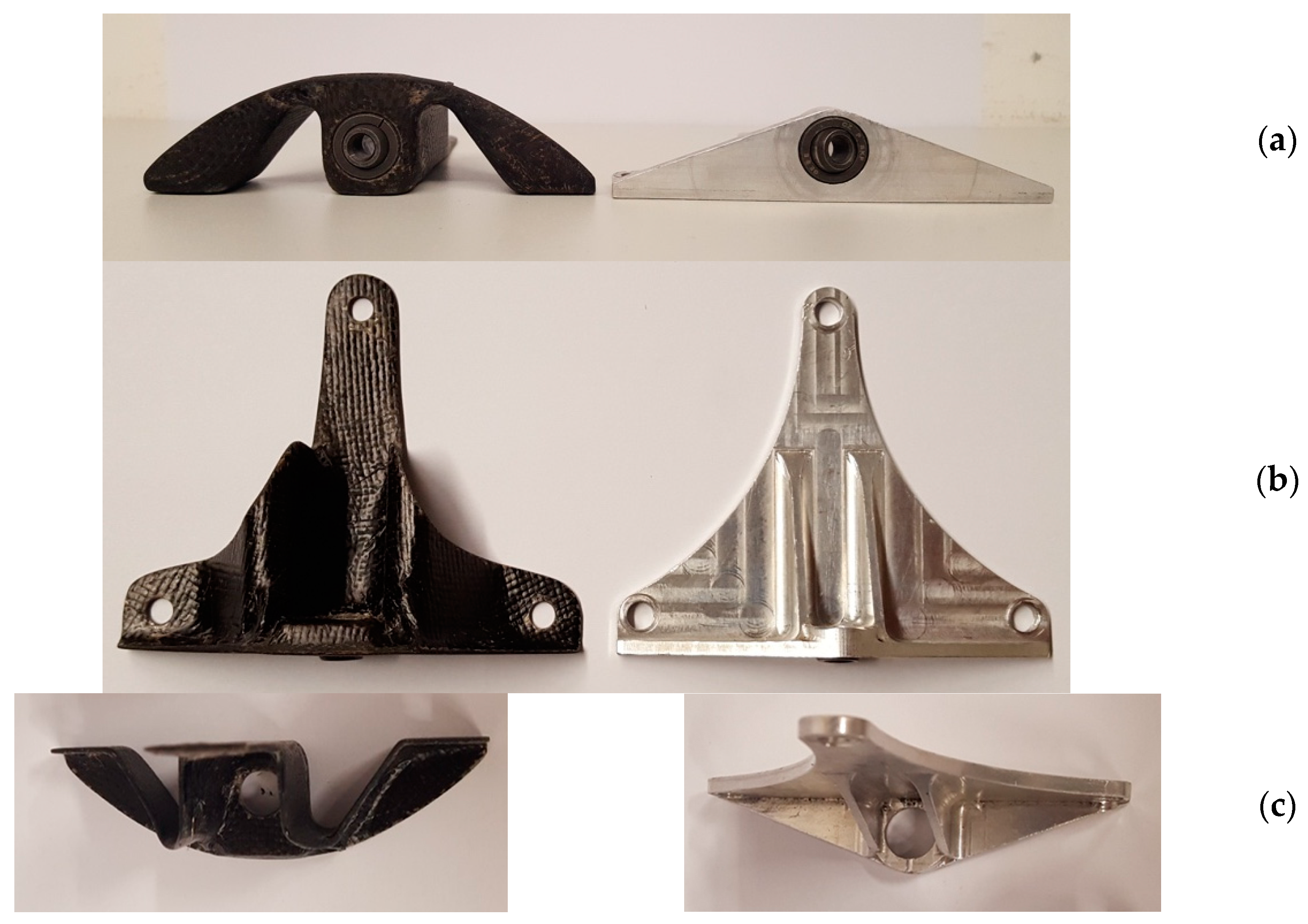
Figure 21.
New BFRP component vs. original aluminum component: (a) Bottom view. (b) Frontal view. (c) Top view.
Figure 21.
New BFRP component vs. original aluminum component: (a) Bottom view. (b) Frontal view. (c) Top view.

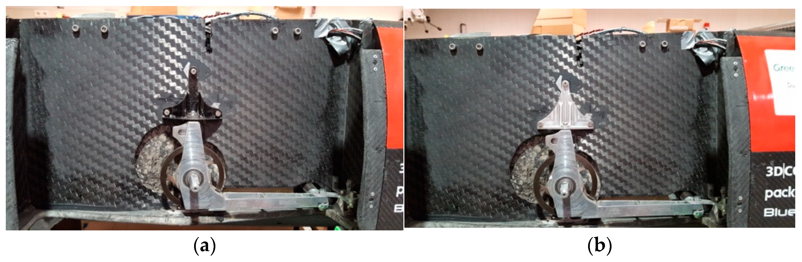
Figure 22.
Component mounted in the prototype: (a) new BFRP component. (b) Original aluminum component.
Figure 22.
Component mounted in the prototype: (a) new BFRP component. (b) Original aluminum component.


Table 1.
Physical and mechanical properties of original component (supplied by KMS – Technical Material, Lda. [23]).
Table 1.
Physical and mechanical properties of original component (supplied by KMS – Technical Material, Lda. [23]).
| Property | Aluminum 7075-T6 |
|---|---|
| Density (g/cm3) | 2.81 |
| Young’s modulus (GPa) | 71.70 |
| Poisson ratio | 0.33 |
| Tensile strength (MPa) | 572.00 |
| Shear modulus (GPa) | 26.90 |
Table 2.
Applied loads on the wheel hub carrier bracket.
| 692.30 | 575.58 | 104.30 | 0 |
Table 3.
Physical and mechanical properties of the starting materials (as mentioned by the supplier).
Table 3.
Physical and mechanical properties of the starting materials (as mentioned by the supplier).
| Property | Epoxy Resin [Supplied by Sicomin] | Basalt Fiber [Supplied by Basaltex NV] |
|---|---|---|
| Density (g/cm3) | 1.10 | 2.67 |
| Young’s modulus (GPa) | 3.20 | 79.30 |
| Poisson ratio | 0.35 | 0.26 |
| Tensile strength (MPa) | 77.00 | 2900–3100 |
| Thickness (mm) | - | 0.13 |
Table 4.
Physical and Mechanical Properties of the basalt fibers (BFRP) composite.
| Property | BFRP Composite |
|---|---|
| Density (g/cm3) | 1.75 ± 0.07 |
| E1 = E2 (GPa) | 18.62 ± 0.38 |
| Poisson ratio | 0.104 ± 0.03 |
| G1 = G2 = G3 (GPa) | 2.9 ± 0.08 |
| Volume of fiber (%) | 60.0 |
| Ply thickness (mm) | 0.18 |
| Tensile Strength (MPa) | 448.4 ± 25.0 |
| Shear Strength (MPa) | 62.8 ± 1.7 |
| Fracture Strain (mm/mm) | 0.022 ± 0.005 |
Table 5.
Properties comparison between the Original and BFRP alternative geometries.
| Property | Original Geometry | BFRP Alternative Geometries | ||||||
|---|---|---|---|---|---|---|---|---|
| A | B | C | D | E | F | G | ||
| Weight (g) | 40.00 | 28.42 | 31.71 | 31.33 | 62.30 | 36.96 | 25.36 | 32.25 |
| Deformation (mm) | 0.02 | 0.68 | 0.40 | 0.26 | 1.30 | 0.04 | 0.71 | 0.06 |
| Tensile Stress (MPa) | 66.73 | 207.50 | 131.56 | 115.48 | 542.95 | 32.26 | 243.67 | 37.18 |
Table 6.
Strain deviations between experimental and finite element method (FEM) results.
| Applied Load (kN) | Strain Deviations (%) | ||
|---|---|---|---|
| Strain Gauge 1 | Strain Gauge 2 | Strain Gauge 3 | |
| 0.5 | 5.26 | 29.59 | 100.00 |
| 1.0 | 27.88 | 2.81 | 71.95 |
| 1.5 | 29.30 | 3.21 | 53.86 |
| 2.0 | 22.22 | 12.98 | 43.18 |
Table 7.
Comparison of mechanical properties.
| Property | Original | BFRP | Variation (%) |
|---|---|---|---|
| Weight (g) | 40.0 | 22.0 | −45 |
| Deformation (mm) | 0.02 | 0.09 | 350 |
| Stress (MPa) | 66.73 | 58.84 | −31.29 |
Publisher’s Note: MDPI stays neutral with regard to jurisdictional claims in published maps and institutional affiliations. |
© 2021 by the authors. Licensee MDPI, Basel, Switzerland. This article is an open access article distributed under the terms and conditions of the Creative Commons Attribution (CC BY) license (https://creativecommons.org/licenses/by/4.0/).
Share and Cite
MDPI and ACS Style
Marat-Mendes, R.; Ribeira, D.; Reis, L. Assessment of Replacement of Metal Parts by BFRP Composites into a Highly Efficient Electrical Prototype. J. Compos. Sci. 2021, 5, 95. https://0-doi-org.brum.beds.ac.uk/10.3390/jcs5040095
AMA Style
Marat-Mendes R, Ribeira D, Reis L. Assessment of Replacement of Metal Parts by BFRP Composites into a Highly Efficient Electrical Prototype. Journal of Composites Science. 2021; 5(4):95. https://0-doi-org.brum.beds.ac.uk/10.3390/jcs5040095
Chicago/Turabian StyleMarat-Mendes, Rosa, Diogo Ribeira, and Luís Reis. 2021. "Assessment of Replacement of Metal Parts by BFRP Composites into a Highly Efficient Electrical Prototype" Journal of Composites Science 5, no. 4: 95. https://0-doi-org.brum.beds.ac.uk/10.3390/jcs5040095