
Demagnetization Effect on the Magnetoelectric Response of Composite Multiferroic Cylinders


1
Experimental Mechanics Laboratory, Mechanical Engineering Department, San Diego State University, 5500 Campanile Drive, San Diego, CA 92182, USA
2
Alkhwarizmi College of Engineering, University of Baghdad, Jaderyia, Baghdad 10071, Iraq
*
Author to whom correspondence should be addressed.
J. Compos. Sci. 2021, 5(5), 139; https://0-doi-org.brum.beds.ac.uk/10.3390/jcs5050139
Submission received: 3 May 2021
/
Revised: 14 May 2021
/
Accepted: 17 May 2021
/
Published: 20 May 2021
(This article belongs to the Special Issue Multiferroic Composite Structures)
Abstract
:Strain-mediated multiferroic composite structures are gaining scientific and technological attention because of the promise of low power consumption and greater flexibility in material and geometry choices. In this study, the direct magnetoelectric coupling coefficient (DME) of composite multiferroic cylinders, consisting of two mechanically bonded concentric cylinders, was analytically modeled under the influence of a radially emanating magnetic field. The analysis framework emphasized the effect of demagnetization on the overall performance. The demagnetization effect was thoroughly considered as a function of the imposed mechanical boundary conditions, the geometrical dimensions of the composite cylinder, and the introduction of a thin elastic layer at the interface between the inner piezomagnetic and outer piezoelectric cylinders. The results indicate that the demagnetization effect adversely impacted the DME coefficient. In a trial to compensate for the reduction in peak DME coefficient due to demagnetization, a non-dimensional geometrical analysis was carried out to identify the geometrical attributes corresponding to the maximum DME. It was observed that the peak DME coefficient was nearly unaffected by varying the inner radius of the composite cylinder, while it approached its maximum value when the thickness of the piezoelectric cylinder was almost 60% of the total thickness of the composite cylinder. The latter conclusion was true for all of the considered boundary conditions.
1. Introduction
The complexity in describing the response of concentric cylinder multiferroic composite structures for magnetoelectric coupling stems from the interactions between three physics domains (namely, mechanics, electrostatics, and magnetism) based on the description of the kinematics [1]. Typically, strain-mediated multiferroic composite structures consist of two or more phases of piezoelectric and piezomagnetic materials bonded together in different configurations [2,3,4]. In such a case, the magnetoelectric coupling is bidirectional, where the application of a magnetic field through the piezomagnetic material results in a spontaneous change in polarization within the piezoelectric phase through the transduction of strain across the interface. Converse coupling is also present, where an electric field applied across the piezoelectric material generates a mechanical strain that is transduced at the interface, yielding a change in the state of magnetization in the piezomagnetic material. It is, however, imperative to note that the cylindrical coordinate system, i.e., the case of the ring or cylinder structure, gives rise to intricate physical interactions including self-boundedness, shape anisotropy, magnetic shielding, non-uniform strain distribution, and geometry- and field-dependent magnetic states, to name a few [5]. Such coupled interactions are the motivation for describing the behavior of these structures as ‘complex.’
Four direct and four converse magnetoelastic effects delineate the strain-magnetization interdependency, focusing on the interaction between the bias magnetic field and the piezomagnetic materials. In the direct sense, the geometry changes in the direction of the applied magnetic field in what is referred to as the Joule magnetostriction [1]. However, the application of a magnetic field also induces a change in the state of magnetization, resulting in a change in the volume (i.e., volume magnetostriction) and the elastic modulus (commonly denoted as the ΔE effect) [1,6]. When considering the converse coupling paradigm, there are inversely analogous effects: the Villari effect, the Nagaoka–Honda effect, and magnetically induced changes in the elastic response, respectively [1]. Concurrent to these geometry-independent effects, three additional kinematically induced effects include magnetic shielding, shape anisotropy, and the onion state of magnetization [7]. The magnetic field preferentially permeates through the walls of a ferromagnetic cylinder due to the higher permeability than the surrounding air media, resulting in shielding the air inclusion created by the cylinder walls. When applied diametrically, the magnetic field creates a non-uniform state of magnetization in the cylinder, where the magnetic field wraps around the cylinder walls in two symmetric half circles (i.e., onion state of magnetization), yielding a strain gradation from the inner to the outer diameter [8,9,10]. Collectively, these bidirectional and spontaneous effects play a significant role in the overall performance of strain-mediated multiferroic composites, given that a large volume fraction of the structure is made of the piezomagnetic cylinder.
The quest to describe the full magneto-electro-mechanical response of strain-mediated multiferroic concentric cylinder structures has been evident in the recent literature from experimental, computational, and analytical approaches [5,8,9,10,11,12,13,14,15,16,17,18,19,20,21,22,23,24,25,26,27,28,29,30,31,32,33,34,35,36,37,38,39,40,41,42,43,44,45,46]. The outcomes of these research efforts further culminate the justification for describing the concentric ring structure as complex. For example, composite ring structures have been experimentally studied, which consisted of an outer piezoelectric cylinder (PZT, lead zirconate titanate) and an inner piezomagnetic ring (Terfenol-D, an alloy of iron, terbium, and dysprosium) operating under the converse magnetoelectric coupling paradigm [5,6,7,8,9,10,11]. Experimentally, it also has been shown that the direction of polarization of the piezoelectric cylinder, the quality and method of interfacing the cylinders, the direction and magnitude of applied bias magnetic field, the frequency and magnitude of the electric field, and the duration of loading influence the overall response symbiotically [5,6,7,8,9,10,11].
Furthermore, several researchers investigated tri-layer cylinders consisting of negative or positive magnetostrictive materials deposited on the interior and exterior surfaces of a thin PZT cylinder using an electroless process [21,25]. They reported the direct magnetoelectric response corresponding to axially and diametrically applied bias magnetic field consisting of superimposed DC and AC components [21,25]. Overall, the outcomes of the existing experimental reports in the literature align with the presumptions of Bichurin and Viehland that the concentric composite cylinder structures are worthwhile to the investigation for magnetoelectric coupling applications [43]. However, it is important to note that there are no experimental investigations, to the knowledge of the authors at the time of the publication of this paper, on the direct magnetoelectric coupling of composite cylinders under the influence of a radially emanating magnetic field. This is due to the practical challenges of experimentally replicating this situation, i.e., constructing a magnetic field source with a radially emanating magnetic field, hence the persistent focus on analytically investigating this boundary-value problem within the realm of continuum mechanics. It is, however, important to note that previous experimental investigations of concentric ring structures have demonstrated the multidirectional emanation of magnetic flux when operating the composite ring under the converse magnetoelectric coupling paradigm [30,44,45,46]. This configuration can then be used to generate and apply an AC magnetic field.
Starting with the pioneer analytical work of Wang et al. using the effective medium theory, to the recent reports by Youssef et al., these analytical models focus on mechanistically describing the dynamic magnetoelectric response of concentric cylinders [30,37,38,39,40,46]. Wang et al. assumed directly and perfectly bonded piezoelectric and magnetostrictive cylinders, and investigated the effect of four mechanical boundary conditions on the overall direct magnetoelectric response [37,38,39,40]. Youssef et al. recently published a subsequent analytical investigation to supplement Wang’s model by considering an expanded set of mechanical boundary conditions [30,46]. They also accounted for the inclusion of an elastic bonding layer; the systematic investigation of the strain distribution, given as the prime mediator between the applied magnetic field and the resulting change in polarization; and the exploration of the failure due to the generated mechanical stresses in all constituents [30,46]. While these models appear to be comprehensive, they make no attempt to investigate the demagnetization effect, negating the applied magnetic field and causing an additional source of non-uniformity for the distribution of the magnetic field within the investigated structure, as shown later. Wang et al. derived expressions for the demagnetizing factors for solid long and short cylinders subjected to a uniform magnetic field along their longitudinal axes [38,39]. Their derivation was mainly formulated as functions of susceptibility and length-to-diameter ratio. Goode and Rowlands also obtained analytical expressions for the demagnetizing energies for long, short, and medium length elliptic cylinders [47] in the form of two partial series for each length. Goode and Rowlands noted that the solution was not suitable for the medium length cylinders, as the series broke down, so they suggested an interpolation based on replacing the ellipse cross section with a rectangle area [47]. The focus of this analytical research then is to explicate the demagnetization influence on the overall magneto-electro-mechanical response of strain-mediated multiferroic composites. In all, the outcomes of the reported research are believed to be essential for the development of magnetoelectric devices based on the cylinder geometry that is tolerant to mechanical failure, since the demagnetization effect may result in strain localization, leading to damage. At the outset, an effort has been dedicated to identifying the geometrical parameters that lead to maximizing the direct magnetoelectric response of these composites.
2. Theory and Problem Formulation
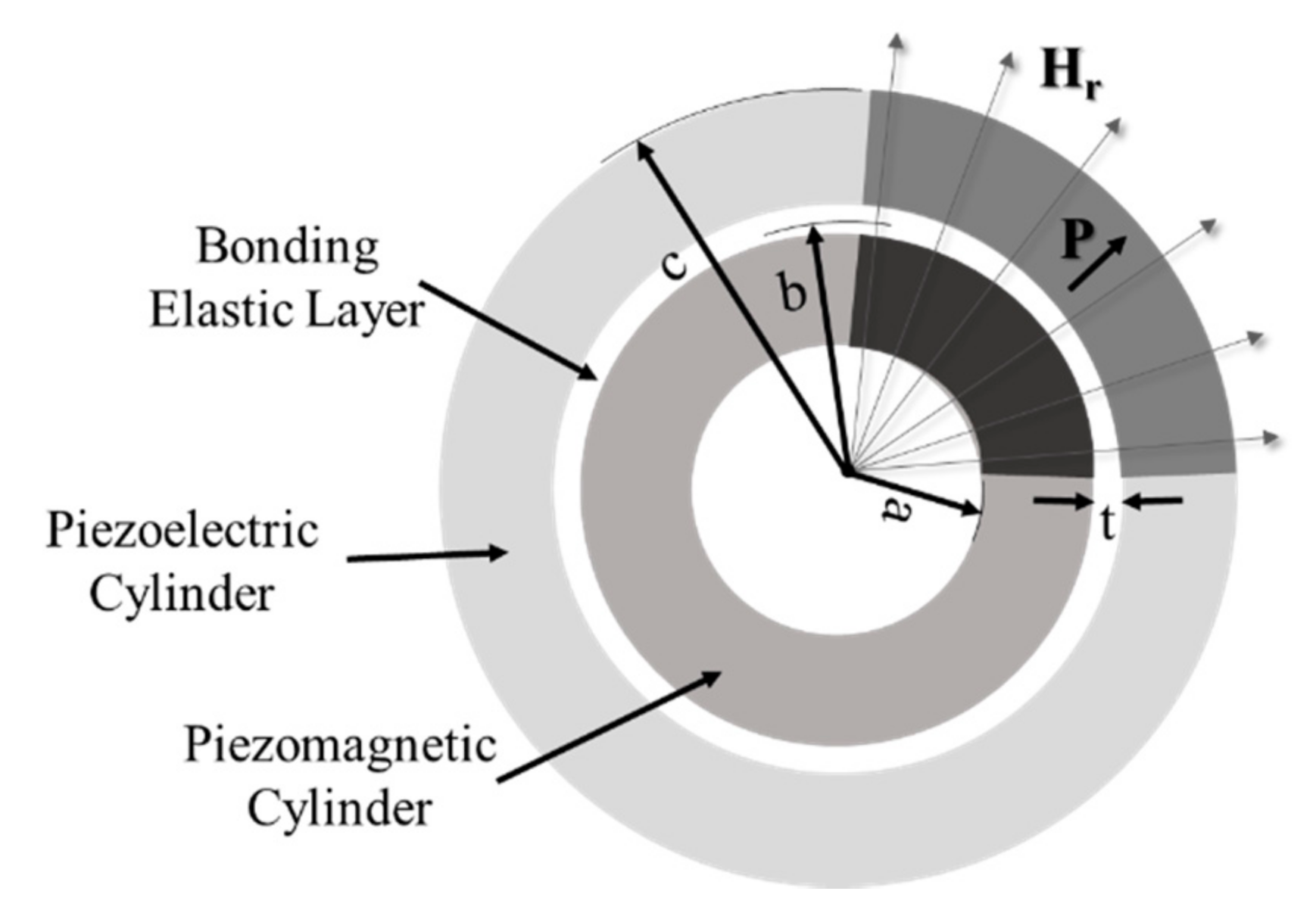
The boundary value problem of a multiferroic composite cylinder structure (Figure 1) consisting of bonded piezoelectric/piezomagnetic cylinders continues to be considered in this research, where the direct magnetoelectric effect (Joule effect) is investigated. It is worth noting, contrary to some prior work, that the active material cylinders are presumed to be assembled using a passive elastic layer that is perfectly bonded to each of the cylinders at separate surfaces. The basic formulation is based on the linear piezoelectric and piezomagnetic constitutive relationships that have been reported a priori by Wang et al. and Youssef et al., but, for the sake of completion [30,37,38,39,40,46], a brief introduction is included below, since the derivation is required to substantiate the newly investigated demagnetization effect.
2.1. Basic Formulation
The outer cylinder is taken to be made of a piezoelectric material that is assumed to be radially polarized and mechanically orthotropic, while the inner cylinder is isotopically piezomagnetic under the effect of a time-harmonic uniform radially emanating magnetic field (). The mechanics formulation follows plane strain assumptions in the polar coordinate system (r, θ) per unit length of the cylinder. Therefore, the hoop and the radial stresses ( and respectively) for the piezomagnetic cylinder can be written as
by noting that: (1) the piezomagnetic material is electrically conductive such that ; (2) the response due to the application of a magnetic field in one direction is independent from the magnetic response in the orthogonal directions (i.e., taken and ); and (3) the cylinder is actuating under a radially applied magnetic field , where the time-harmonic factor () was dropped to simplify the derivation given that all terms are similarly affected by it [37,38,39,40]. The Bessel differential equation for the piezomagnetic cylinder (Equation (3)) is recovered after substituting the equations of stresses into the expression for mechanical equilibrium.
where,
Following the same procedure for the outer piezoelectric cylinder, the components of the stresses in the polar coordinate system can also be written as shown in Equations (4) and (5).
In this case, three assumptions are applied to the outer cylinder based on the behavior of piezoelectric materials, which include: (1) the response of the piezoelectric cylinder is independent of the magnetic field; (2) charge accumulation at the outer surfaces of the cylinder is prohibited such that ; and (3) the piezoelectric cylinder is considered to be radially polarized given rise to the condition of . Therefore, the equation of the radial electric displacement () can be written by following the linear piezoelectric constitutive relationship as shown in Equation (6).
Again, a Bessel differential equation of the radial displacement in the piezoelectric cylinder as a function of the properties is given by
where,
As previously reported, the general solutions of the Bessel differential equation, Equations (3) and (7), are given in Equation (8) for the piezomagnetic cylinder and Equation (9) for the piezoelectric cylinder in terms of the first and second Bessel functions and of order μ, respectively [37,38,39,40].
where,
The unknown coefficients AE, BE, AM, and BM in Equations (8) and (9) are to be found from the boundary conditions and continuity conditions (discussed later).
2.2. Demagnetization Effect Consideration
The passing of a magnetic field through a ferromagnetic material results in a change in magnetization, which, in turn, emanates a magnetic flux. However, the effective magnetic field is reduced from the applied magnetic field due to the demagnetization effect, where the latter is a function of the emanating magnetic flux from the sample that is corrected by a geometry-specific demagnetization factor (). In all, the effective magnetic field () acting on the sample can be expressed as shown in Equation (11), which is used to substitute for the magnitude of the radial magnetic field () as discussed in Equations (1)–(3).
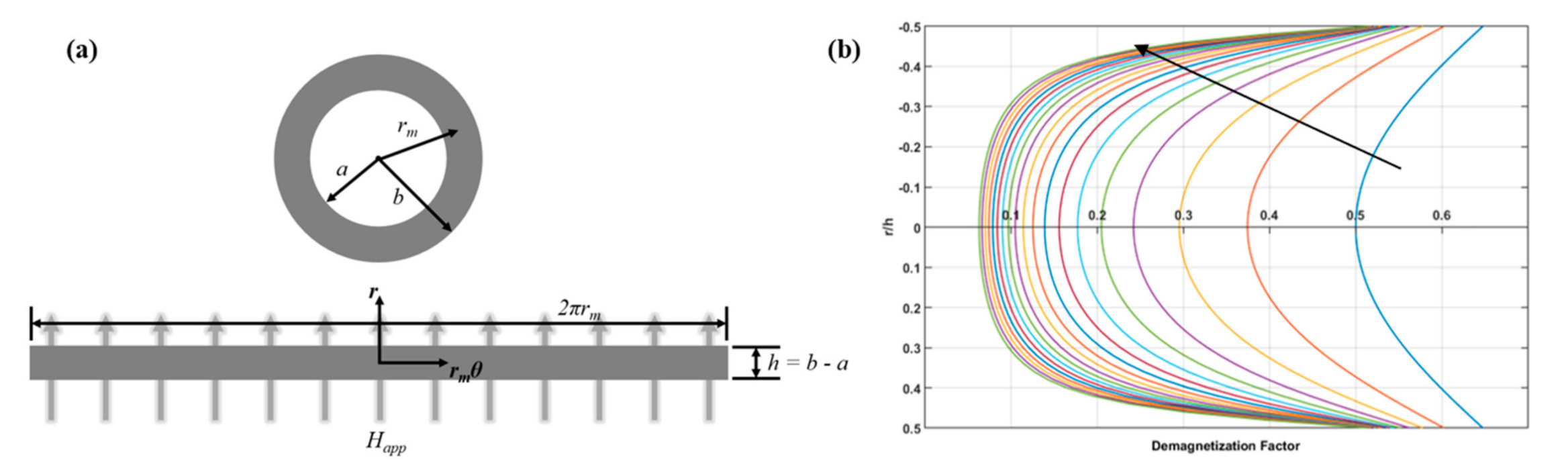
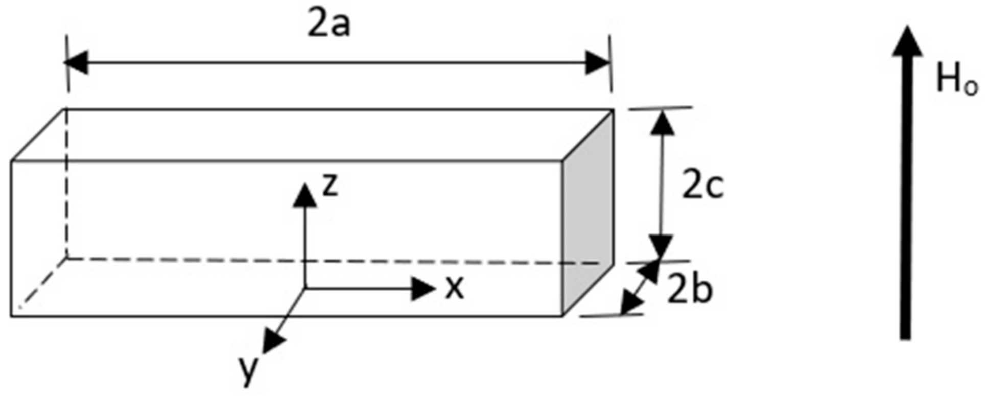
The demagnetization factor has been documented before in the literature for many geometries, for single crystal and polycrystalline materials [7]. To estimate the demagnetization factor without resorting to solving the Poisson’s equation, the following assumptions are introduced, which stem from the kinematics of the concentric composite cylinder and the magnetic boundary condition. As discussed above, the magnetic field is applied radially outward from the center, hence Happ is assumed to be applied uniformly over the circumference of the cylinder. That is to say, the demagnetization effect is occurring in a plane and in the radial direction only, where it is circumferentially uniform. This assumption then further simplifies the problem, where the cylindrical geometry is considered as a prism, as shown in Figure 2a. Hence, according to Joseph et al. [48], (see Appendix A), the demagnetization factor is defined as
where,
with rm is the mean radius, h is the wall thickness in the radial direction, and w is the wall width in the longitudinal direction, all dimensions are of the piezomagnetic cylinder. Since the magnetic field is considered to be uniformly distributed along the circumference, the contribution in the θ-direction is neglected. The demagnetization factor is then dependent on the geometry and on the direction of the applied magnetic field. The demagnetization factor is plotted in Figure 2b as a function of the wall thickness ranging from 0.002 m to 0.02 m. In the case under investigation here, the demagnetization factor is independent of the mean radius, since the applied magnetic field was assumed uniform outward from the center. As thickness increases, the effect of the demagnetization field is minimized such that Nd ≈ 0, indicating that the effective magnetic field becomes equivalent to the applied field. Generally, Figure 2b signifies the dependence of the demagnetization factor on the geometry of the piezomagnetic cylinder.
2.3. Solution of the Boundary-Value Problem (No Demagnetization Effect)
To find the unknown coefficients in Equations (8) and (9), four mechanical boundary conditions are considered in addition to above-stated electrical and magnetic boundary conditions. The mechanical boundary conditions (Table 1) include free and clamped conditions on the inner- and outermost surfaces of the composite cylinder.
The continuity boundary condition has been modified by Youssef et al. [30] after the inclusion of a bonding elastic layer (Equation (14)), where they discussed the effect of the elastic adhesive layer on the overall magnetoelectric coefficient.
where, ks is the characteristic stiffness of the bonding elastic layer and given by Equation (15) in terms of the elastic properties of the material (E is the modulus of elasticity and ν is the Poisson’s ratio) and the geometry of the bonding layer (r is the mean radius and t is the thickness).
In the case of a bonding layer-free interface where the piezoelectric and magnetic electric cylinders are directly bonded to one another, the continuity condition of direct bonding is shown in Equation (16).
Thereafter, the ME coupling coefficient (Equation (17)) is calculated after applying the boundary and continuity conditions to find the unknown coefficients [32].
2.4. Solution of the Boundary-Value Problem (with Demagnetization Effect)
When the demagnetization effect is considered, the applied magnetic field () in Equation (1) is replaced by the effective magnetic field ( defined in Equation (11) as discussed above. This substitution implies that the forcing function is no longer a constant, rather, it becomes a function of the radial direction, i.e., Heff is a function of r since the demagnetization factor () is radially dependent, as shown in Equation (12). The resulting differential equation can then be solved by the Lagrange’s method of variation of parameters, where the general solution consists of two terms such that is the complementary solution given by Equation (18) and is the particular solution defined by Equation (19).
Once the total solution is determined, the magnetoelectric coefficient can be calculated using the same procedure as above.
The material properties of the outer piezoelectric cylinder, elastic bonding layer, and inner piezomagnetic cylinder are listed in Table 2, which were used in obtaining the solution of the boundary-value problem with and without accounting for the demagnetization effect.
3. Results and Discussions
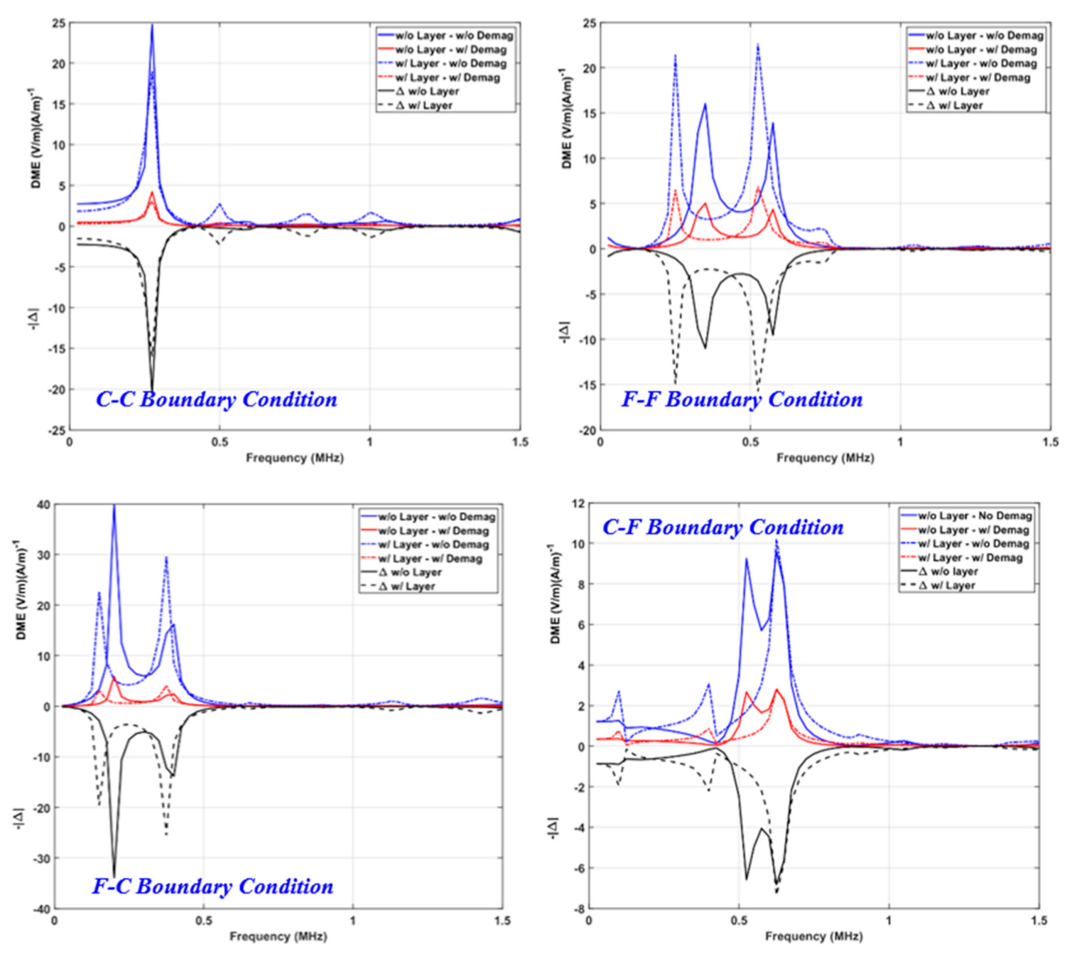
Figure 3 shows the direct magnetoelectric coupling coefficient as a function of frequency ranging from 0.1 MHz to 1.5 MHz for all four considered mechanical boundary conditions while elucidating the dependence of the DME on the presence of the elastic bonding layer and the demagnetization effect. The total radial thickness of the composite cylinder was 5 mm, whereas the inner radius was 10 mm, the interface radius was 12 mm, and the outer radius was 15 mm. The applied magnetic field was taken to be 60 kA/m based on the magnetic saturation behavior of Terfenol-D. This justifies the exclusion of nonlinear material effects for the current model. It is important to note that the previous analytical studies pointed towards the paramount importance of geometrical dimensions in preselecting the resonance frequency, even more important than the values of the coupling coefficients [27]. When considered, the thickness of the elastic bonding layer was taken to be 7.5 μm, based on the research outcomes from [30]. The composite Figure 3 also demonstrates the effect of the mechanical boundary conditions on the DME coupling coefficient. Specifically, the figure consists of four sub-figures, each representing clamped–clamped, free–free, free–clamped, and clamped–free boundary conditions defined on the inner and outer diameters of the composite cylinder, respectively. Additionally, plotted at the bottom of each sub-figure is the difference between DME responses with and without the demagnetization factor accounted for when the bonding layer was suppressed or sanctioned. The difference subplots qualitatively and quantitatively show that the demagnetization effect is more pronounced in the response region corresponding to the initial dynamics, i.e., in the vicinity of the first and second harmonics. In all, the DME maxima and the associated resonant frequencies depended on the boundary conditions, the demagnetization effect, and the bonding layer.
As the frequency increased beyond the fundamental harmonic, the resulting DME coupling coefficient was substantially lower, as expected, than the peak values at the resonance. For example, the DME values at the first resonant frequency for the F-F boundary condition were 5.04 (V/m)(A/m)−1 (at 350 kHz) and 6.51 (V/m)(A/m)−1 (at 250 kHz) for the scenario when the demagnetization effect was considered in the presence and absence of the bonding layer, respectively. Thereafter, the demagnetization-modified peak DME value for the same boundary condition was merely 4.36 (V/m)(A/m)−1, associated with a frequency of 575 kHz when the bonding layer was sanctioned. Correspondingly, the peak DME was 6.88 (V/m)(A/m)−1 at 525 kHz in the absence of the bonding layer. The diminished high-frequency response was attributed to the deexcitation of radially expanding vibrational modes, but this can be effectively tuned to meet specific design requirements by manipulating of the geometrical and material attributes.
3.1. Effect of Boundary Conditions
The mechanical boundary conditions play a major role in the overall DME response, including the peak values, the corresponding frequencies, and the attributes of the waveforms of the resonant frequencies. In this section, the focus is on the interrelationship between the resulting DME coupling coefficient and the applied boundary condition; therefore, the discussion is limited to the case of the absence of demagnetization and a bonding layer (the remaining scenarios are considered in the following sections). The maximum DME response was 29.57 (V/m)(A/m)−1 when the inner diameter of the composite was mechanically free, while the outer diameter was clamped at a frequency of 375 kHz. The maximum DME values for the remaining boundary conditions were 19.06, 22.65, and 10.2 (V/m)(A/m)−1, for the C-C, F-F, and C-F conditions, respectively, occurring at the corresponding frequencies of 275, 525, and 625 kHz. It is worth noting that the electrical and magnetic boundary conditions remained unchanged throughout the analysis, as noted in the model section. The sensitivity of the magnetoelectric coupling coefficient to the change in the mechanical boundary conditions stems from two specific reasons.
First, the change in the boundary conditions corresponds to a change in the apparent structural stiffness of the composite cylinder, hence not only shifting the frequency but also affecting the values of the coupling coefficient. In recent research, our group formalized the interrelationship between a comprehensive set of mechanical boundary conditions, including those used herein; the materials’ properties; and the geometrical attributes of each of the constituents in what we termed the normalized stiffness parameter [46]. The latter was then used to investigate the sensitivity of the DME response, signifying the contribution of each of the abovementioned factors. The manipulation of the boundary conditions for the same geometrical and material attributes can dynamically tune the DME frequency response for hardware-agnostic antennas and filters.
Second, the type of the applied boundary condition dedicates the distribution of the radial displacement field within each constituent phase of the composite. The results in Figure 3 clearly signify that the type (free vs. clamped) and location (inner vs. outer diameter) of a boundary condition have a defining contribution on the efficiency of strain transfer from the inner actuator piezomagnetic cylinder to the outer piezoelectric sensor cylinder. For example, clamping the outer surface of the piezoelectric cylinder while prescribing a stress-free boundary condition at the inner diameter of the piezomagnetic cylinder (i.e., F-C) resulted in the highest DME coefficient. This maximum is due to the fact that the transferred radial displacement to the outer cylinder resulted in an increase in electrical displacement due to the enhanced piezoelectric strain.
3.2. Effect of Bonding Layer
The addition of the elastic bonding layer had a profound effect on the magnetoelectric coupling coefficient, as shown in Figure 3, while disregarding the demagnetization effect (discussed next). The DME values in the presence of a bonding layer were 29.6% and 34.5% higher than when the layer’s effect was suppressed in the cases of the outer diameter of the composite cylinder being clamped for the C-C and F-C conditions, respectively. On the other hand, i.e., when the outer diameter was free, the bonding layer appeared to have an adverse effect such that the DME values were 5.9% and 29.1% lower in comparison to the results when the bonding layer was absent for the C-F and F-F boundary conditions, respectively. For example, the peak values of the DME coefficient for the case of the F-C boundary condition were found to be 39.8 (V/m)(A/m)−1 and 29.6 (V/m)(A/m)−1 when the elastic bonding layer was sanctioned and suppressed, respectively. Similarly, the maximum DME changed from 24.7 to 19.1, from 9.6 to 10.2, and from 16.1 to 22.7 (V/m)(A/m)−1 for the C-C, C-F, and F-F conditions, respectively. The presence of the elastic layer and the clamping of the outer diameter promoted the transfer of the radial displacement from the inner actuator cylinder to the outer piezoelectric cylinder, resulting in improved DME values. In other words, the efficacy of the strain mediation was enhanced by the presence of the bonding layer that acted as a mechanical mediator, transitioning the difference in the elastic properties of the inner and outer cylinders. On the other hand, constraining the outer boundary gave rise to higher piezoelectric coupling since the difference in the radial displacement across the piezoelectric cylinder was amplified. While a single thickness of the bonding layer was considered herein, the increase in thickness was recently reported to affect the underlying strain transduction phenomenon that is primarily responsible for the magnetoelectric coupling paradigm under consideration [30].
In addition to affecting the amplitude of the DME coupling coefficient, accounting for the effect of an ultrathin bonding layer resulted in shifting the resonant frequencies. For example, the frequency of the first-harmonic was 250, 150, and 350 kHz for the F-F, F-C, and C-F boundary conditions, respectively, in the absence of the effect of the elastic layer. In contrast, these frequencies accordingly shifted to 350, 200, and 525 kHz due to modifying the continuity condition to account for the presence of the elastic layer. In the case of clamped–clamped mechanical boundary condition, and regardless of the inclusion or exclusion of the bonding layer effect, the first harmonic frequency remained unchanged at 275 kHz. The insensitivity of the resonant frequency in the C-C boundary condition is attributed to the dominance of the stiffness of the piezoelectric and piezomagnetic cylinders, deeming the contribution of the ultrathin and compliant elastic layer negligible in this case. Otherwise, the elastic layer, being more compliant than the other active constituents (see material properties in Table 2), affects the effective stiffness of the composite structure, which in turn shifts the resonance frequency. It is important to note, as discussed earlier, that the mechanical boundary conditions also affected the latter. Not only can the frequency be veered depending on the geometrical and material attributes of the elastic bonding layer, but the bandwidth can also be alternated by changing the thickness of this passive mediation layer, as discussed recently by Youssef et al. [30]. In all, these findings collectively point towards the suitability of the investigated composite structure for the development of tunable magnetic filters, with importance in the high-frequency communication realm.
3.3. Effect of the Demagnetization Field
Figure 2b signifies the dependence of the demagnetization factor on the wall thickness of the piezomagnetic cylinder, where a decrease in the wall thickness resulted increased the effect of the demagnetization factor. On the contrary, an increase in the thickness showed that the effective magnetic field is nearly equivalent to the applied field, i.e., the demagnetization factor approaches zero. The direct magnetoelectric coupling coefficient values were influenced by the demagnetization effect, which resulted in reducing the resulting DME, as expected, since the effective magnetic field was lowered by the demagnetization factor. On the other hand, also foreseen, the location of the resonant frequency is independent of the inclusion of the demagnetization effect in the calculations leading to the DME response due to the essence of the demagnetization factor being a geometrical construct with no physical link to the mechanical, electrical, or magnetic properties of the constituents. To better illustrate the dependence, the difference between the DME coupling coefficients was calculated and plotted at the bottom of Figure 3 for each DME-frequency response, amounting to a difference ranging between 7.35 and 25.53 (V/m)(A/m)−1, with a strong dependence on the boundary conditions, as discussed before.
The DME of the composite cylinder at the first resonant frequency o changed due to the demagnetizing effect from 19.1 to 3.1, 22.65 to 6.9, 29.6 to 4.1, and 10.2 to 2.9 (V/m)(A/m)−1, respectively, for the C-C, F-F, F-C, and C-F mechanical boundary conditions. This amounted to a decrease in the DME by 83.9%, 69.6%, 86.3%, and 72.1%, respectively. As discussed above, the effect of demagnetization energy is inevitable given its linkage to the geometry and size of the device under investigation. That is, while the results presented thus far compare the effect of the demagnetization on the DME response to elucidate its negative influence, the demagnetization factor must be included in future analytical modeling of concentric cylinders. It is also important to note that the adverse influence of the demagnetization is amplified near the peripheries, in our case, the inner and outer diameter, where the demagnetization factor is maximum and approaches nearly the same value as shown in Figure 2b. This is of specific importance to the spatial distribution of the radial strains that will degrade the localized and, in turn, the global, magnetoelectric response of the composite structure.
3.4. Effect of the Geometry
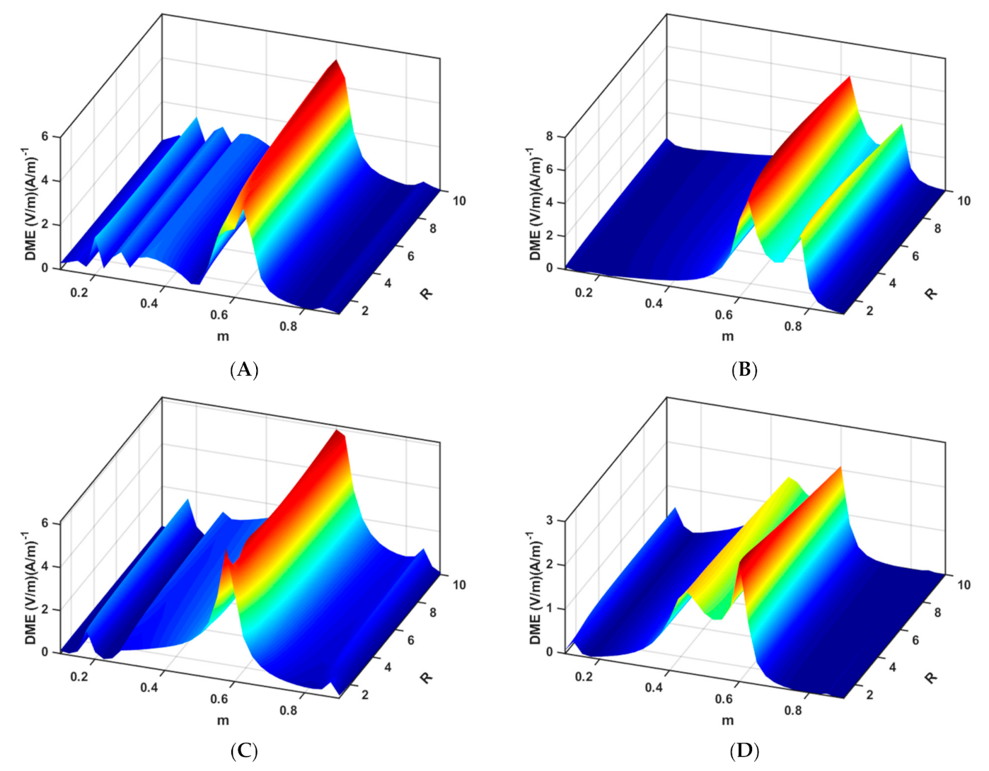
Based on the preceding discussions, there are three overarching conclusions. First, the mechanical boundary conditions can be used to enhance the magnetoelectric response as a function of frequency by effectively changing not only the amplitude, but also the resonant frequency. Second, the elastic layer, which is important for the practical assembly of the cylinder, also plays a notable role in the value and the resonant frequency of the DME response. Finally, the demagnetization effect is imperative to account for, given its major contribution to the over magnetic energy based on the geometry. However, these conclusions were curated based on specific geometrical attributes of the composite cylinder, leaving a gap in formalizing the overall dependence on geometry. It is then the objective of this section to demonstrate the interrelationship between the geometry and the DME for all mechanical boundary conditions in the presence of the elastic bonding layer and by accounting for the demagnetization factor. In essence, Figure 4 presents a search schema within the design envelope to identify the conditions leading to the maximum DME response.
Figure 4 plots the DME coupling coefficient as a function of two normalized geometrical parameters, namely the sensor phase ratio () and the inner radius ratio (), at the corresponding first resonant frequency for each mechanical boundary condition. In the calculations leading to Figure 4, the effect of the elastic layer was also included by continuing to take the thickness to be 7.5 μm. The m ratio was taken to be [0.1:0.9], signifying that the piezoelectric cylinder occupying 10% to 90% of the overall thickness. The R ratio was [1:10], representing a range of inner radius that ranges from 5 mm to 50 mm. As evident from the previous results and the underlying elastodynamic response, the resonant frequency is dependent on the boundary condition and was calculated a priori for the C-C, C-F, F-C, and F-F scenarios using Equation (A9) included in the Appendix B. The derivation of the resonant frequency equations can be found in Appendix B.
The maximum magnetoelectric coupling coefficient shows a higher dependency on the sensor phase ratio than the inner radius ratio, regardless of the boundary condition. That is, for a given m value, the DME remains constant over the entire range of R values, which is consistent with the previous results. The change in the geometry has a far-reaching influence on the DME values, especially when considering the geometry-driven demagnetization factor. The latter depends on the portion of the overall thickness associated with the inner piezomagnetic cylinder such that a change in m influences the fraction of Terfenol-D in the overall composite. In other words, as the m ratio increases, the thickness of the piezoelectric cylinder also increases, resulting in a proportional reduction in the thickness of the piezomagnetic cylinder since the overall thickness was kept constant. This, in turn, amplifies the demagnetization factor and negatively affects the DME. On the other hand, the change in the inner radius, i.e., change in the R ratio, has no bearing on the demagnetization factor, resulting in a constant DME over the entire range of R. In closing, Figure 4, and the associated equations and discussion, complete the analytical modeling framework to fully investigate the considered concentric composite cylinder for direct magnetoelectric coupling with possible applications for tunable magnetic filters and energy harvesting.
3.5. Model Limitations
On the limitations of the present model, it is worth noting that while the current formulation includes several physical phenomena regarding the dynamic response of concentric composite multiferroic cylinders, it includes two limitations. First, the model makes no attempt to account for the behaviors of the magnetic spin, electromagnetic waves, and acoustic waves, which require the amendment of the current framework to include the Landau–Lifshitz–Gilbert equation and Maxwell equations. Second, the model does not consider the time and temperature-dependent properties of the composite cylinders and the elastic bonding layer.
4. Conclusions
The presented model pursued the study of the geometrical effects on the direct magnetoelectric coupling response of concentric composite multiferroic cylinders. Concurrently investigated was the influence of the mechanical boundary and the continuity conditions. The results obtained from the proposed analysis indicate that the DME was found to show a strong dependence on the geometrical construction of the demagnetization effect, where the latter has a drastic, adverse effect on the calculated DME coefficient, whether the separating thin elastic layer was sanctioned or suppressed, and regardless of the considered boundary conditions. Moreover, the harmonic frequencies at which the peak DME occurred were also proven to be independent of the demagnetization factor, given that it is a geometrical construction does not affect the stiffness or inertia of the constituents. Finally, the effect of the geometrical attributes of the composite cylinder were probed in detail to elucidate the overall design space of these composites. While future research is warranted on the proposed model to include the dynamics of the multiferroic systems, the results are promising for future investigations on developing of multiferroic-based devices such as magnetic filters and energy harvesters.
Author Contributions
Conceptualization, S.N. and G.Y.; methodology, S.N. and G.Y.; formal analysis, S.N. and G.Y.; investigation, S.N. and G.Y.; data curation, S.N. and G.Y.; writing—original draft preparation, S.N. and G.Y.; writing—review and editing, S.N. and G.Y.; visualization, S.N. and G.Y. All authors have read and agreed to the published version of the manuscript.
Funding
This research received no external funding.
Conflicts of Interest
The authors declare no conflict of interest.
Nomenclature
| a | Inner radius of the inner cylinder |
| b | Radius at the interface between cylinders |
| c | Outer radius of the outer cylinder |
| t | Thickness of the elastic layer |
| r | Radial direction |
| θ | Hoop direction |
| E | Modulus of elasticity of the elastic layer |
| G | Modulus of rigidity |
| ρ | Mass density |
| ν | Poisson’s ratio of the elastic layer material |
| Ks | Stiffness of the elastic layer |
| Ho | Magnetic field |
| Happ | Applied magnetic field |
| Heff | Effective magnetic field |
| Nd | Demagnetization factor |
| μr | Relative permittivity of the piezomagnetic material |
| eij | Piezoelectric coefficients |
| qij | Piezomagnetic coefficients |
| Cij | Elastic coefficients |
| ε33 | Dielectric coefficient |
| Uθ | Hoop and radial displacement |
| Ur | Radial displacement |
| Dr | Electric displacement in the radial direction |
| Er | Electric field in the radial direction |
| Ω | Frequency |
| γ | Shear strain |
| τ | Shear stress |
| Fθ | Body forces in the hoop direction |
| Fr | Body forces in the radial direction |
| σθθ | Hoop stresses |
| σrr | Radial stresses |
| α | Direct Magnetoelectric Coefficient |
| Subscripts | |
| M | Piezomagnetic cylinder |
| E | Piezoelectric cylinder |
Appendix A
Figure A1.
Rectangular prism subjected to uniform magnetic field Ho.

The demagnetization factor in z-direction is,
where,
Assuming that it is required to obtain the demagnetization factor in the (x-z) plane, at which y = 0, hence,
and,
Converting to polar coordinates and assuming that,
substituting in Equations (A3) and (A4), to obtain,
where,
Appendix B
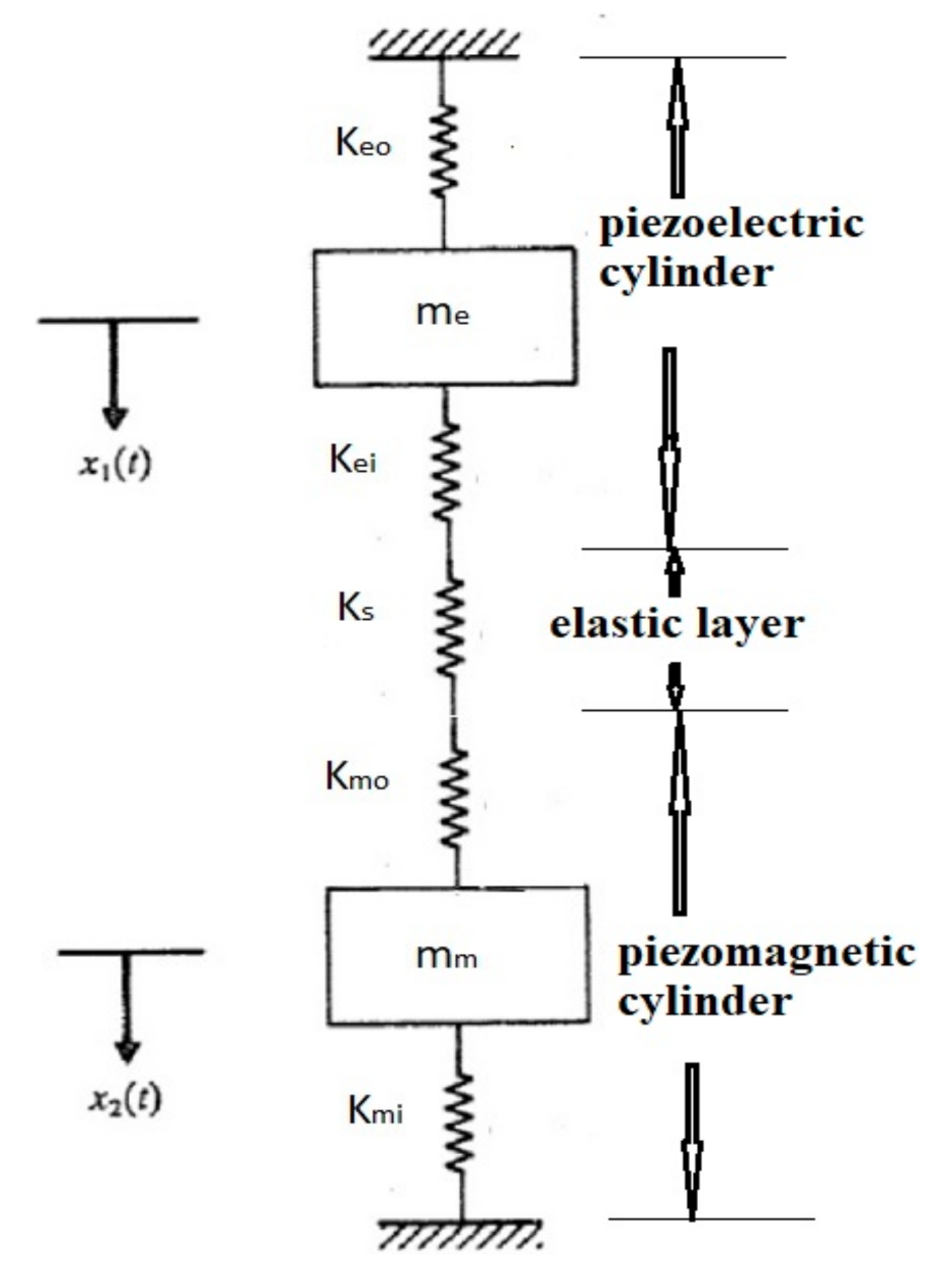
In order to investigate the harmonic frequencies of the system, the composite cylinder is modeled as shown in Figure A2 using the lumped parameters approach.
Figure A2.
Dynamic model of the composite cylinder.

The equation of motion for the above model can be written in matrix form as
where, Ke is the equivalent stiffness, found to be,
Equation (A7) was then solved to arrive to the resonant frequency equation
where, is the mass of the piezoelectric cylinder ( and is the mass of the piezomagnetic cylinder () while taking ρe as the mass density of the piezoelectric material and ρm as the mass density of the piezomagnetic material. The stiffness of each layer is evaluated by
where, E and ν are the modulus of elasticity and Poisson’s ratio of the material, respectively. For the C-C boundary condition, all stiffnesses have values, while for the F-F boundary condition (Keo = Kmi = 0), the F-C boundary condition (Kmi = 0), and for the C-F boundary condition (Keo = 0).
References
- Liang, X.; Dong, C.; Chen, H.; Wang, J.; Wei, Y.; Zaeimbashi, M.; He, Y.; Matyushov, A.; Sun, C.; Sun, N. A Review of Thin-film Magnetoelastic Materials for Magnetoelectric Applications. Sensors 2020, 20, 1532. [Google Scholar] [CrossRef] [PubMed] [Green Version]
- Nan, C.W.; Bichurin, M.I.; Dong, S.; Viehland, D.; Srinivasan, G. Multiferroic Magnetoelectric Composites: Historical Perspective, Status, and Future Directions. J. Appl. Phys. 2008, 103, 1. [Google Scholar] [CrossRef]
- Palneedi, H.; Annapureddy, V.; Priya, S.; Ryu, J. Status and Perspectives of Multiferroic Magnetoelectric Composite Materials and Applications. Actuators 2016, 5, 9. [Google Scholar] [CrossRef] [Green Version]
- Cheng, Y.; Peng, B.; Hu, Z.; Zhou, Z.; Liu, M. Recent Development and Status of Magnetoelectric Materials and Devices. Phys. Lett. A 2018, 382, 3018–3025. [Google Scholar] [CrossRef]
- Youssef, G.; Newacheck, S.; Lopez, M. Mapping Magnetoelastic Response of Terfenol-D Ring Structure. Appl. Phys. Lett. 2017, 110, 192408. [Google Scholar] [CrossRef]
- Chopra, H.D.; Ravishankar, A.; Pacifico, M.S.; Forst, M.L. Non-Joulian Magnetostriction and Non-Joulian Magnetism. Phys. Status Solidi Basic Res. 2018, 255, 1–15. [Google Scholar] [CrossRef] [Green Version]
- Cullity, B.; Graham, C. Introduction to Magnetic Materials; IEEE Press: Piscataway, NJ, USA, 2009. [Google Scholar]
- Youssef, G.; Lopez, M.; Newacheck, S. On the Effect of Polarization Direction on the Magnetoelectric Response of Multiferroic Composite Rings. Smart Mater. Struct. 2017, 26, 037003. [Google Scholar] [CrossRef] [Green Version]
- Newacheck, S.; Webster, T.; Youssef, G. The Effect of Multidirectional Bias Magnetic Fields on the Converse Magnetoelectric Response of Multiferroic Concentric Composite Ring. Appl. Phys. Lett. 2018, 113, 172902. [Google Scholar] [CrossRef]
- Chavez, A.; Lopez, M.; Youssef, G. Converse Magneto-electric Coefficient of Concentric Multiferroic Composite Ring. J. Appl. Phys. 2016, 119, 233905. [Google Scholar] [CrossRef]
- Newacheck, S.; Youssef, G. Wireless Energy Transfer based on Strain-mediated Composite Multiferroics. Smart Mater. Struct. 2020, 29, 015014. [Google Scholar] [CrossRef]
- Ming, L.C.; Wing, O.S.; Ho, S.L. High Current Sensitivity and Large Magnetoelectric Effect in Magnetostrictive-piezoelectric Concentric Ring. J. Appl. Phys. 2014, 115, 17A933. [Google Scholar] [CrossRef]
- Hong, H.; Bi, K.; Wang, Y.G. Magnetoelectric Performance in Ni/Pb(Zr,Ti)O3/FeCo Trilayered Cylindrical Composites. J. Alloys Compd. 2012, 545, 182–185. [Google Scholar] [CrossRef]
- Hong, H.; Bi, K.; Wu, W.; Chen, F.G. Controllable Resonance Frequency in Ni/Pb(Zr,Ti)O3/FeCo Cylindrical Composites. Mater. Res. Innov. 2014, 18, 231–234. [Google Scholar] [CrossRef]
- Yakubov, V.; Xu, L.; Volinsky, A.A.; Qiao, L.; Pan, D. Edge Geometry Effects on Resonance Response of Electroplated Cylindrical Ni/PZT/Ni Magnetoelectric Composites. AIP Adv. 2017, 7, 085305. [Google Scholar] [CrossRef] [Green Version]
- Xu, L.R.; Pan, D.A.; Zuo, Z.J.; Wang, J.; Volinsky, A.A.; Qiao, L.J. Multi-electrode Pb(Zr,TiO)3/Ni Cylindrical Layered Magnetoelectric Composite. Appl. Phys. Lett. 2015, 106, 2013–2016. [Google Scholar] [CrossRef]
- Xu, L.; Qiao, L.; Pan, D.; Volinsky, A.A. Lorentz Force Induced Magnetoelectric Effect in Cylindrical Composites with PZT/Magnetostrictive and Nonmagnetic Metal Layers. J. Alloys Compd. 2018, 730, 483–486. [Google Scholar] [CrossRef]
- Xu, L.; Yan, Y.; Qiao, L.; Wang, J.; Pan, D.; Yang, S.; Volinsky, A.A. Layer Thickness and Sequence Effects on Resonant Magnetoelectric Coupling in Ni/Pb(Zr,Ti)O3 Cylindrical Composites. Mater. Lett. 2016, 185, 13–16. [Google Scholar] [CrossRef]
- Wu, G.; Zhang, R.; Zhang, N. Enhanced Converse Magnetoelectric Effect in Cylindrical Piezoelectric-magnetostrictive Composites. EPJ Appl. Phys. 2016, 76, 1–7. [Google Scholar] [CrossRef]
- Xu, L.; Pan, D.; Qiao, L.; Volinsky, A.A.; Song, Y. Directional Magnetoelectric Effect in Multi-electrode Pb(Zr,Ti)O3/Ni Cylindrical Layered Composite. Mater. Des. 2016, 89, 173–176. [Google Scholar] [CrossRef] [Green Version]
- Ge, X.H.; Ji, H.; Li, Y.; Chen, J.K.; Wang, Y.G. Diameter and Sequence Effects on Magnetoelectric Effect in FeCo/Pb(Zr,Ti)O3/Ni Trilayered Long Cylindrical Composite Structures. J. Alloys Compd. 2018, 752, 303–307. [Google Scholar] [CrossRef]
- Song, Y.; Pan, D.; Xu, L.; Liu, B.; Volinsky, A.A.; Zhang, S. Enhanced Magnetoelectric Efficiency of the Tb1-xDyxFe2-y/Pb(Zr,Ti)O3 Cylinder Multi-electrode Composites. Mater. Des. 2016, 90, 753–756. [Google Scholar] [CrossRef]
- Shen, H.Q.; Wang, Y.G. Tunable Resonant Frequency of FeCo/PZT/FeCo Cylinders. Int. J. Mod. Phys. B 2013, 27, 1–7. [Google Scholar] [CrossRef]
- Pan, D.A.; Zhang, S.G.; Tian, J.J.; Sun, J.S.; Volinsky, A.A.; Qiao, L.J. Resonant Modes and Magnetoelectric Performance of PZT/Ni Cylindrical Layered Composites. Appl. Phys. A Mater. Sci. Process. 2010, 98, 449–454. [Google Scholar] [CrossRef] [Green Version]
- Pan, D.A.; Bai, Y.; Chu, W.Y.; Qiao, L.J. Ni-PZT-Ni Trilayered Magnetoelectric composites Synthesized by Electro-deposition. J. Phys. Condens. Matter 2007, 20, 025203. [Google Scholar] [CrossRef] [Green Version]
- Pan, D.A.; Wang, J.; Zuo, Z.J.; Zhang, S.G.; Liu, B.; Volinsky, A.A.; Qiao, L.J. Improved Magnetoelectric Performance of the Ni-P/Ni/Pb(Zr,TiO)3 Cylindrical Layered Composites. Appl. Phys. Lett. 2014, 105, 102902. [Google Scholar] [CrossRef] [Green Version]
- Pan, D.A.; Bai, Y.; Volinsky, A.A.; Chu, W.Y.; Qiao, L.J. Giant Magnetoelectric Effect in Ni-lead Zirconium Titanate Cylindrical Structure. Appl. Phys. Lett. 2008, 92, 052904. [Google Scholar] [CrossRef]
- Li, Y.D.; Xiong, T.; Cai, Q.G. Coupled Interfacial Imperfections and Their Effects on the Fracture Behavior of a Layered Multiferroic Cylinder. Acta Mech. 2015, 226, 1183–1199. [Google Scholar] [CrossRef]
- Ootao, Y.; Ishihara, M. Transient Thermoelastic Analysis of a Laminated Hollow Cylinder Constructed of Isotropic Elastic and Magneto-Electro-Thermoelastic Materials. Adv. Mater. Sci. Appl. 2013, 2, 48–59. [Google Scholar] [CrossRef]
- Youssef, G.; Nacy, S.; Newacheck, S. Dynamic Magnetoelectric Response of Composite Multiferroics Cylinders. Smart Mater. Struct. 2020, 29, 35025. [Google Scholar] [CrossRef]
- Zhang, J. Effect of Boundary Conditions on Magnetocapacitance Effect in a Ring-type Magnetoelectric Structure. Phys. Lett. A 2017, 381, 3909–3916. [Google Scholar] [CrossRef]
- Zhang, R.; Wu, G.; Zhang, L.; Zhang, N. Theory of Frequency Response of Magnetoelectric Effects in Radially Polarized Thin Cylindrical Composites. Eur. Phys. J. Appl. Phys. 2014, 65, 10602. [Google Scholar] [CrossRef]
- Gao, Y.W.; Zhang, J.J. Nonlinear Magneto-electric Response of a Giant Magnetostrictive/Piezoelectric Composite Cylinder. Acta Mech. Sin. 2012, 28, 385–392. [Google Scholar] [CrossRef]
- Huang, Y.; Zhang, C.L. Magnetoelectric Effect in a Circumferentially Polarized Composite Cylinder. Smart Mater. Struct. 2013, 22, 105018. [Google Scholar] [CrossRef]
- Pan, D.A.; Zhang, S.G.; Volinsky, A.A.; Qiao, L.J. Simple Model of the Magnetoelectric Effect in Layered Cylindrical Composites. J. Phys. D Appl. Phys. 2008, 41, 205008. [Google Scholar] [CrossRef]
- Wang, X.; Zhong, Z. A Finitely Long Circular Cylindrical Shell of Piezoelectric/Piezomagnetic Composite under Pressuring and Temperature Change. Int. J. Eng. Sci. 2003, 41, 2429–2445. [Google Scholar] [CrossRef]
- Wang, H.M.; Liu, C.B.; Ding, H.J. Dynamic Behavior of Piezoelectric/Magnetostrictive Composite Hollow Cylinder. Arch. Appl. Mech. 2009, 79, 753–771. [Google Scholar] [CrossRef]
- Wang, H.M.; Pan, E.; Chen, W.Q. Enhancing Magnetoelectric Effect via the Curvature of Composite Cylinder. J. Appl. Phys. 2010, 107, 093514. [Google Scholar] [CrossRef]
- Wang, H.M.; Pan, E.; Chen, W.Q. Large Multiple Resonance of Magnetoelectric Effect in a Multiferroic Composite Cylinder with an Imperfect Interface. Phys. Status Solidi Basic Res. 2011, 248, 2180–2185. [Google Scholar] [CrossRef]
- Wang, H.M.; Pan, E.; Chen, W.Q. Magnetoelectric Effects in Bilayer Multiferroic Core-shell Composites. Available online: https://0-www-degruyter-com.brum.beds.ac.uk/document/doi/10.1515/jmmm-2016-0151/html (accessed on 19 May 2021).
- Wei, Y.K.; Wang, H.M.; Zou, L. Influence of Curvature on Magnetoelectric Effect of Three-layered Piezoelectric/Piezomagnetic Composite Cylinder. In Proceedings of the 2012 Symposium on Piezoelectricity, Acoustic Waves, and Device Applications (SPAWDA), Shanghai, China, 23–25 November 2012; pp. 137–139. [Google Scholar]
- Ying, J.; Wang, H.M. Magnetoelectroelastic Fields in Rotating Multiferroic Composite Cylindrical Structures. J. Zhejiang Univ. Sci. A 2009, 10, 319–326. [Google Scholar] [CrossRef]
- Bichurin, M.I.; Viehland, D.D. Magnetoelectricity in Composites; Pan Stanford Pub: Singapore, 2012. [Google Scholar]
- Newacheck, S.; Youssef, G. Magnetoelectricity beyond Saturation. Mater. Horiz. 2020, 7, 2124–2129. [Google Scholar] [CrossRef]
- Youssef, G.; Newacheck, S.; Lopez, M.; Stampfli, R. Triaxial Magnetic Flux Emanation in Response to Uniaxial Electric Field in Magnetoelectric Composite Cylinder Structure. Phys. Status Solidi 2020, 217, 2000177. [Google Scholar] [CrossRef]
- Youssef, G.; Somer, N.; Scott, N. Leveraging strain localization to improve the performance of magnetoelectric composite cylinders. EPL 2020, 131, 14003. [Google Scholar] [CrossRef]
- Goode, D.A.; Rowlands, G. The Demagnetizing Energies of a Uniformly Magnetized Cylinder with an Elliptic Cross-section. J. Magn. Magn. Mater. 2003, 267, 373–385. [Google Scholar] [CrossRef]
- Joseph, R.I.; Schlömann, E. Demagnetizing field in nonellipsoidal bodies. J. Appl. Phys. 1965, 36, 1579–1593. [Google Scholar] [CrossRef]
Figure 1.
Schematic of the geometry of the considered boundary-value problem.

Figure 2.
(a) Schematic of (top) the inner piezomagnetic cylinder with its defining geometrical parameters and (bottom) prism resulting from unfolding the cylinder along its circumference, and (b) the calculated demagnetization factor as function thickness (arrow indicate increasing thickness from 0.002 to 0.02 m) based on Equation (12).

Figure 3.
The frequency-dependent DME response of a concentric composite cylinder for four mechanical boundary conditions; at the bottom of each figure is the difference between the responses when the demagnetization effect was considered and suppressed.
Figure 3.
The frequency-dependent DME response of a concentric composite cylinder for four mechanical boundary conditions; at the bottom of each figure is the difference between the responses when the demagnetization effect was considered and suppressed.

Figure 4.
The peak DME values at the resonant frequency as function of the m and R ratio for (A) C-C, (B) F-F, (C) F-C, and (D) C-F boundary conditions.
Figure 4.
The peak DME values at the resonant frequency as function of the m and R ratio for (A) C-C, (B) F-F, (C) F-C, and (D) C-F boundary conditions.


Table 1.
List of considered mechanical boundary conditions at the inner (r = a) and outer (r = c) radii of the composite cylinder (Figure 1).
Table 1.
List of considered mechanical boundary conditions at the inner (r = a) and outer (r = c) radii of the composite cylinder (Figure 1).
| Location | Boundary Conditions | |||
|---|---|---|---|---|
| Free–Free | Clamped–Free | Free–Clamped | Clamped–Clamped | |
Table 2.
Material properties of the piezoelectric, piezomagnetic, and the elastic bonding layer [30].
Table 2.
Material properties of the piezoelectric, piezomagnetic, and the elastic bonding layer [30].
| Material | Property | Value | Unit |
|---|---|---|---|
| PZT-5A | Ρ | 7500 | [kg m−3] |
| c11 | 99.201 | [GPa] | |
| c13 | 50.778 | [GPa] | |
| c33 | 86.856 | [GPa] | |
| e13 | −7.209 | [N C−1] | |
| e33 | 15.118 | [N C−1] | |
| ε33 | 1.5 × 10⁻⁸ | [C2 N−1 m−2] | |
| Terfenol-D | Ρ | 9200 | [kg m−3] |
| c11 | 8.451 | [GPa] | |
| c13 | 3.91 | [GPa] | |
| c33 | 28.3 | [GPa] | |
| q13 | −5.75 | [N A−1 m−1] | |
| q33 | 270.1 | [N A−1 m−1] | |
| Bonding | E | 0.1 | [GPa] |
| Layer | Υ | 0.4 |
Publisher’s Note: MDPI stays neutral with regard to jurisdictional claims in published maps and institutional affiliations. |
© 2021 by the authors. Licensee MDPI, Basel, Switzerland. This article is an open access article distributed under the terms and conditions of the Creative Commons Attribution (CC BY) license (https://creativecommons.org/licenses/by/4.0/).
Share and Cite
MDPI and ACS Style
Nacy, S.; Youssef, G. Demagnetization Effect on the Magnetoelectric Response of Composite Multiferroic Cylinders. J. Compos. Sci. 2021, 5, 139. https://0-doi-org.brum.beds.ac.uk/10.3390/jcs5050139
AMA Style
Nacy S, Youssef G. Demagnetization Effect on the Magnetoelectric Response of Composite Multiferroic Cylinders. Journal of Composites Science. 2021; 5(5):139. https://0-doi-org.brum.beds.ac.uk/10.3390/jcs5050139
Chicago/Turabian StyleNacy, Somer, and George Youssef. 2021. "Demagnetization Effect on the Magnetoelectric Response of Composite Multiferroic Cylinders" Journal of Composites Science 5, no. 5: 139. https://0-doi-org.brum.beds.ac.uk/10.3390/jcs5050139