
Novel Reactive Flex Configuration in Kiwi Wing Foil Surfboard


1
School of Engineering, Telford Innovation Campus, University of Wolverhampton, Telford TF2 9NT, UK
2
Principal Lecturer in Composite Engineering, School of Engineering/Room SC-34, Telford Innovation Campus, University of Wolverhampton, Telford TF2 9NT, UK
*
Author to whom correspondence should be addressed.
J. Compos. Sci. 2022, 6(1), 6; https://0-doi-org.brum.beds.ac.uk/10.3390/jcs6010006
Submission received: 27 November 2021
/
Revised: 21 December 2021
/
Accepted: 23 December 2021
/
Published: 26 December 2021
(This article belongs to the Special Issue Feature Papers in Journal of Composites Science in 2021)
Abstract
:The creation of an ideal surfboard is art. The design and construction depend on the individual surfer’s skill level and type of the required performance. In this research, four fuselage concepts were carefully explored to meet the following unique needs: lightweight, strong, and a fast-manufacturing process. The fuselages were manufactured by compression moulding using skin and core materials. The skin material was selected to be unidirectional (UD) carbon fibre, discontinuous carbon fibre (SMC) and Filava quadriaxial fibre impregnated with epoxy, while the core material was selected to be lightweight PVC foam. To assess the mechanical performance, three-point bending has been performed according to BS-ISO 14125 and validated using Finite Element Analysis (FEA) using Ansys software. As expected, the flexural test revealed that the UD carbon fibre fuselage was the strongest and SMC was the weakest, while large deflection was seen in Filava fibre fuselages before failure, showing great reactive flex that promotes projection during surfing. The experimental results show good agreement with FEA simulation, and the locations of the physical failure in the fuselage matches the location of maximum flexural stress obtained from FEA simulation. Although all fuselages were found to carry a surfer weight of 150 kg, including a factor of safety 3, except the SMC fuselage, due to shrinkage. The Filava fibre fuselages were seen to have a large deflection before failure, showing great flexibility to handle high ocean waves. This promotes the potential use of reactive flex in high performance sports equipment, such as surfing boards. A large shrinkage must be taken under consideration during compression moulding that depends on fibre orientation, resin nature, and part geometry.
Keywords:
reactive flex; carbon fibre; Filava fibre; 3-point bend; fuselage; wing foil; FEA simulation1. Introduction
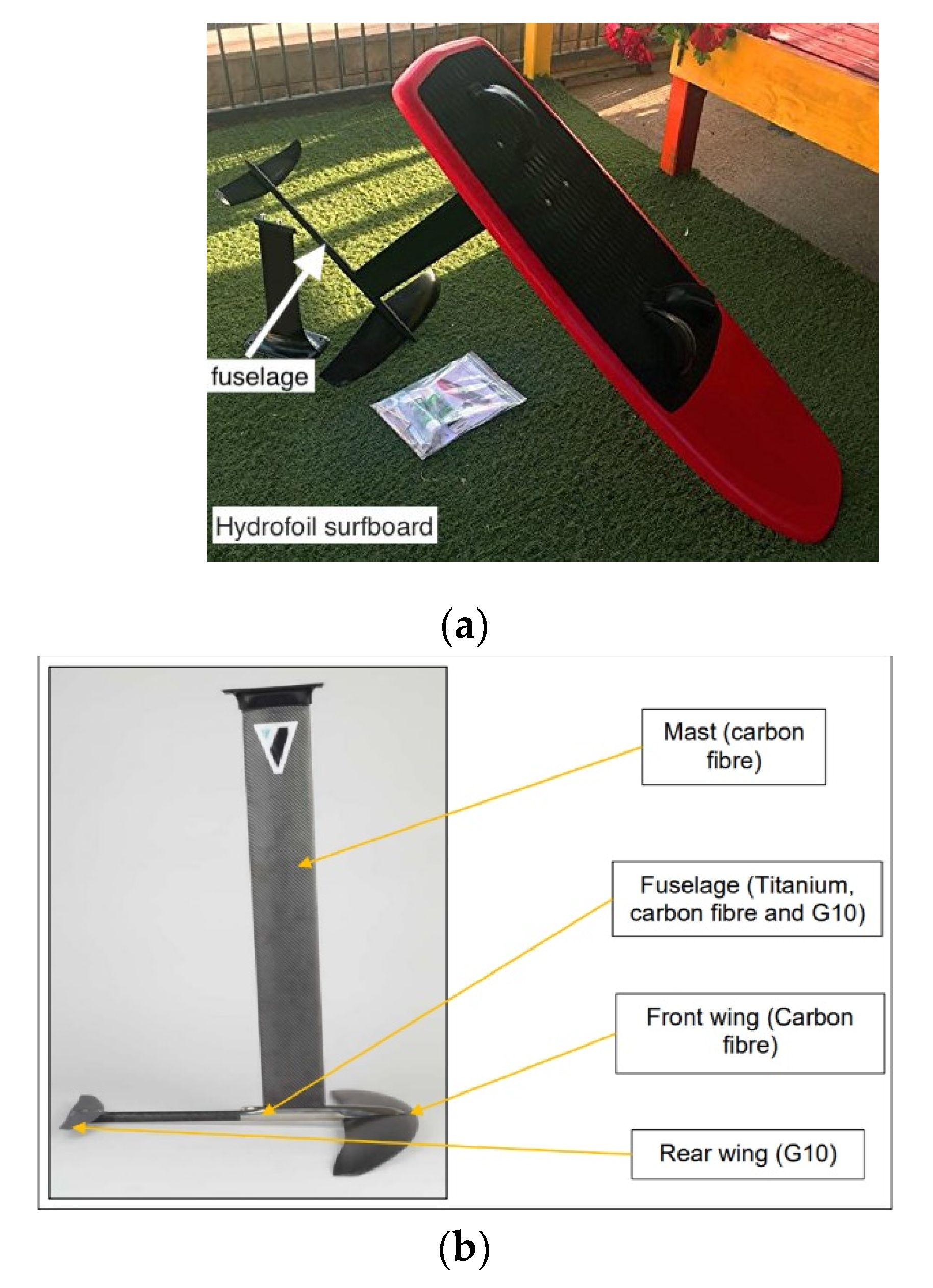
Bending in a surfboard plays a vital role in surfing performance; the principal comes from the board bending, or flexing, into the shape of the wave with the force put down on it, and how it bends back into original shape. It stores up all that energy and releases it, projecting the surfer forward. This causes build-up energy in the board as it is bending out of its natural shape. A wing foil surfboard is a combination of a wing surfer, which is similar to a small kite, and a short surfboard that is bolted to a wing foil, as shown in Figure 1a. The wing foils are made up of four parts, the mast, fuselage, front wing, and rear stabilizer, as shown in Figure 1b. The fuselage is generally between 60 cm and 90 cm long—the shorter the fuselage the better the handle manoeuvring during surfing. However, the longer the mast, the better the surf on waves without the board continually hitting the water. Fuselages can be made from carbon fibre-reinforced polymer (CFRP), titanium or aluminium. However, CFRP is stiffer, lighter, and stronger than aluminium, but it comes with a higher price tag. Aluminium fuselages are more flexible but enable surfing to happen at a cheaper price, with the downside of being heavier than CFRP. A titanium alloy fuselage is more durable and stronger than aluminium, but it is heavier and comes with a much higher price tag [1]. The trade price of ordinary prepreg CFRP is prohibitively high for many other industry sectors, as follows: £26.0/kg, compared to raw unmachined steel, aluminium and titanium at £10.30/kg, £20.36/kg and £50.5/kg, respectively [2]. The trade price of Filava woven fabric is £25/kg [3].
Fuselages are usually fixed to the mast and are made from generally solid CFRP; however, for high performance application, titanium has been used in the Kiwi model fuselage shown in Figure 1b to obtain high strength during manoeuvring. Fuselages are designed to hold the front wing and rear stabilizer, and a smaller fuselage turns faster; hence, it must have a high specific stiffness and strength, whereas bigger wings have a larger turning circle and are slower but will keep the wing foil surfboard above the water longer [4].
In this paper, four fuselage concepts were designed based on a skin-core configuration of fibre epoxy reinforced composite to replace the fuselage model made from Hybrid titanium/CFRP/GFRP. The new concept locks lightweight core with strong skin in a compression moulding process, while maintaining unique reactive flex characteristics during surfing. The aim is to reduce the cost of the fuselage without compromising the strength or stiffness of the fuselage and preserve the reactive flex, which plays a vital element in projection of surfing on high ocean waves.
A reactive flex is complex criteria that depend on fibre orientation and stress direction in wing foil surfboard, which can produce massive torsional leverage forces. To improve durability, longevity, and strength, a range of skin materials combined with lightweight PVC foam has been investigated. The manufacturing process of fuselages has been simplified by using two steel female pattern tools heated in a compression moulding process.
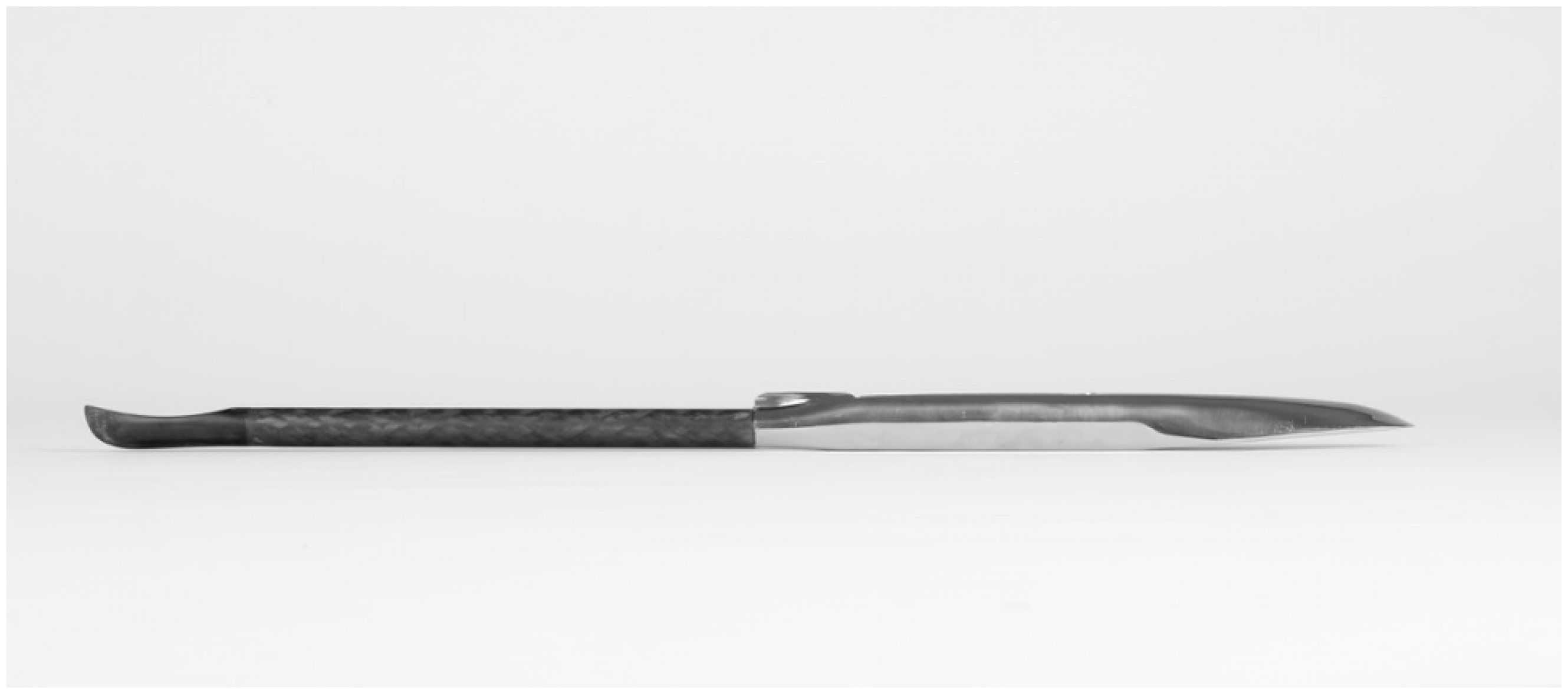
The original concept illustrated in Figure 2 shows a Kiwi model tri-sectional fuselage, a titanium front section, CFRP mid-section, and glass fibre reinforced polymer (GFRP) tail section. This complex concept has a lengthy manufacturing time that restricts high production rate and increases cost. The specific demand is to find a composite material that approaches or exceeds the mechanical properties of the existing materials and simplifies the manufacturing process, hence it was vital to change the manufacturing process to embrace faster production time.
Titanium alloy has remarkable mechanical properties and is exceptionally strong for its weight. Common alternatives, such as steel or aluminium, were rejected, since composites such as CFRP were found lighter than steel and aluminium alloy by 60% and 35%, respectively.
We will be investigating four material concepts using the following epoxy matrix: carbon chopped fibre sheet moulding compound (HexMC), CFRP unidirectional (UD) 600 gsm, and Filava fibres in the following two various weave patterns: Twill 2/2, 200 gsm and quasi quadriaxial 400 gsm. An overview of the mechanical strength of alternative materials is listed in Table 1 according to the manufacture material data sheet [5].
HexMC composite is a cost-effective alternative material developed by Hexcel Plc. It has been used for many years in manufacturing internal aircraft cabins in the Airbus A350 and Boeing B787 [6]. HexMC is chopped unidirectional carbon fibres impregnated with epoxy resin and randomly oriented and is considered as discontinuous fibre composites [7]. HexMC has an interesting property, which is that it guarantees a compromise between high production rate and excellent finish, due to its fast-curing cycle and low resin viscosity properties. Furthermore, the fibre sizing quality ensures a good fibre–matrix interface, and the demoulding properties are considered to be excellent [8].
Filava woven fabric is produced by Isomatex Plc/Belgium and is based on enhanced mechanical and physical properties of basalt fibre by adjusting metal oxides in the molten pool. The latest investigations on using Filava fibre as a reinforcement for composite showed a great advantage over conventional glass and asbestos fibres by demonstrating good elastic modulus and tensile strength [5]. Other advantages explaining enthusiasm around this material are plentiful (e.g., eco-friendly, non-toxic, anti-frictional, non-hazardous, non-flammable) [9]. Filava fibre offers high tensile strength, elongation, and high thermal resistance (up to 950 °C) in improving the properties by 30% compared to basalt fibre [10].
2. Methodology
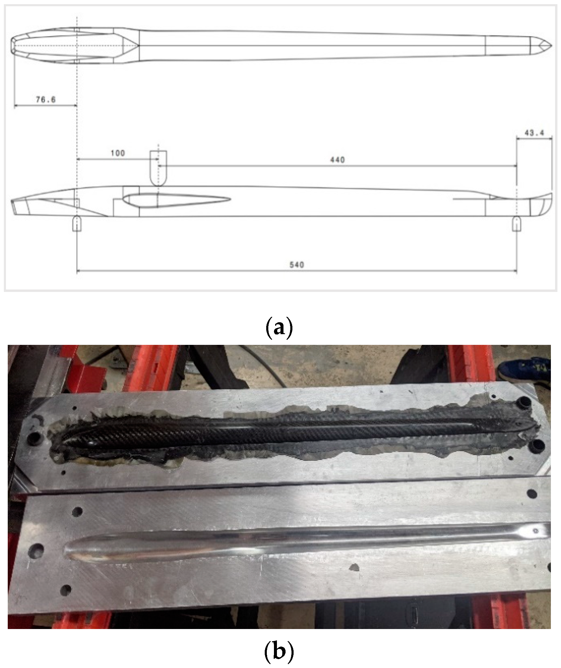
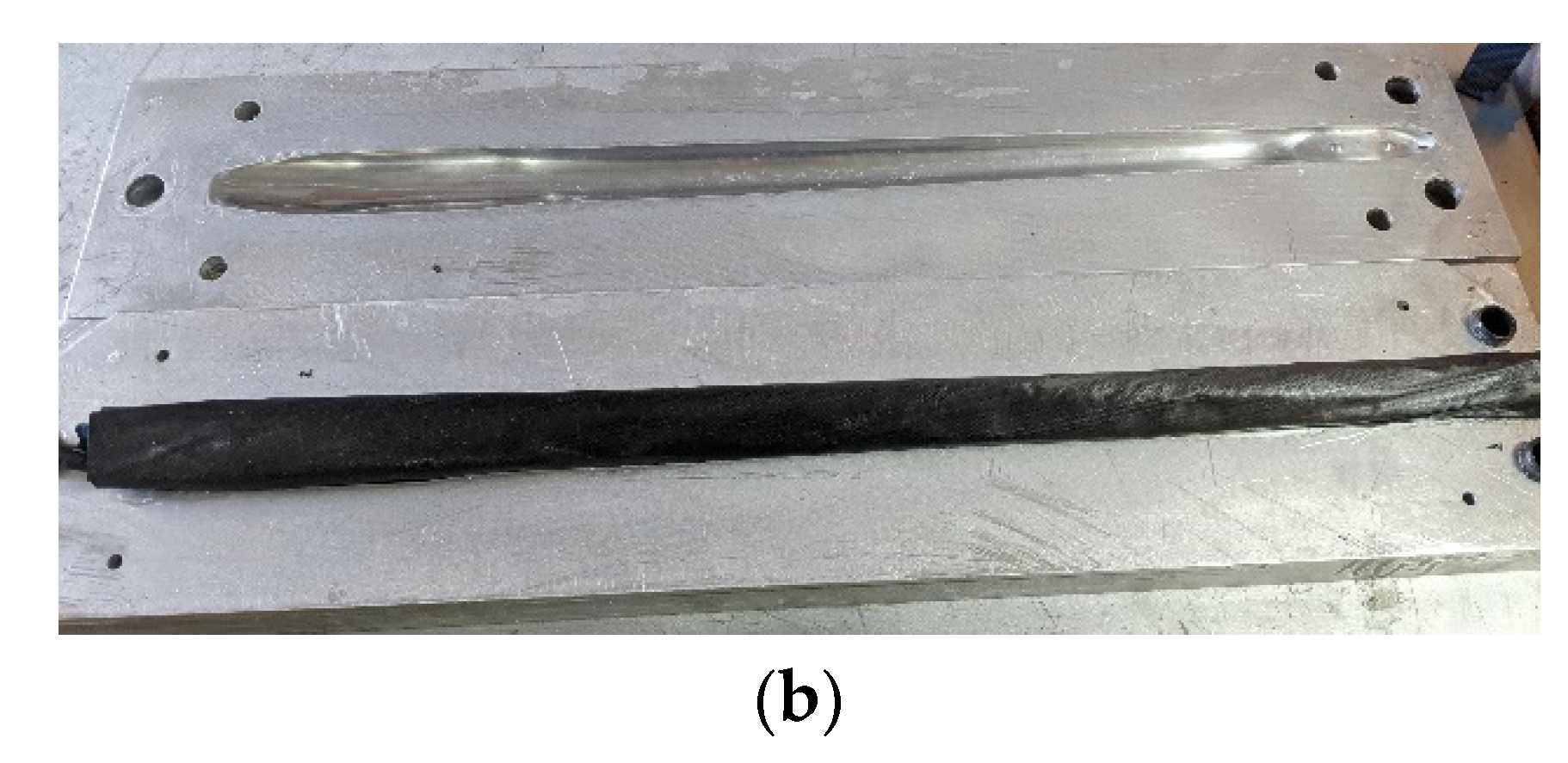
A CAD model fuselage of length 670 mm was developed as shown in Figure 3a. Two aluminium blocks have been 3-axis CNC-machined to produce female pattern and polished to 100-micron surface finish, as shown in Figure 3b.
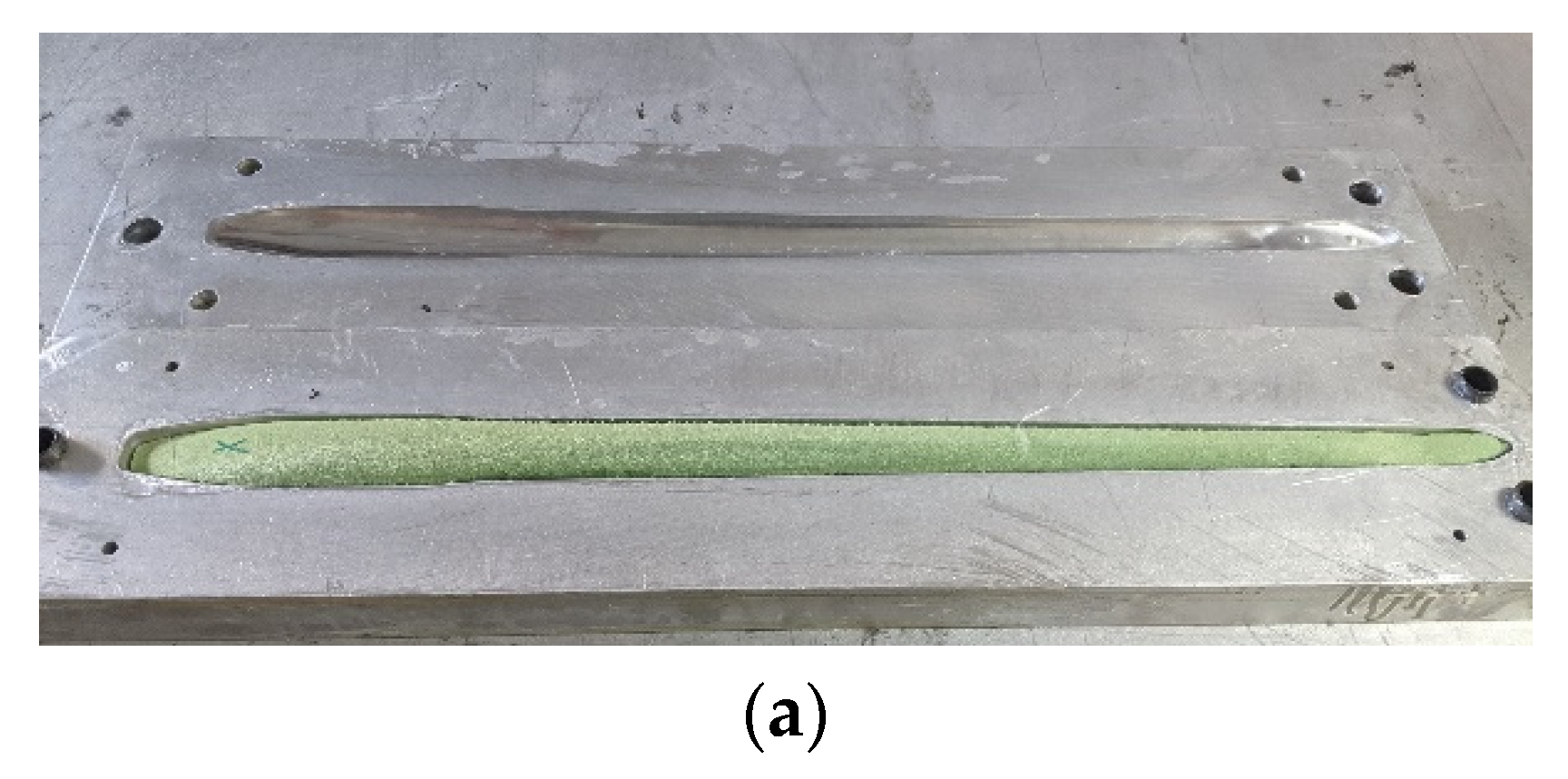
The core material was selected to be an expanded PVC foam (density 80 kg/m3, service temperature 120 °C) and was machined to conform to the female mould, as shown in Figure 4a. The foam geometry was designed to have 2 mm surface offset to accommodate the skin filling material. Four different skin concepts were laminated around the foam and conformed accurately the mould pattern as shown in Figure 4b. The prepreg sheet was wrapped up around the foam and clamping the two female moulds were under hydraulic press at 120 °C for 40 min, while HexMC needed only 8 min to cure.
Four different skins were laminated in the mould. The first choice was 4 inside plies of Prepreg CFRP-UD and one outside ply of Twill 2/2 CFRP.
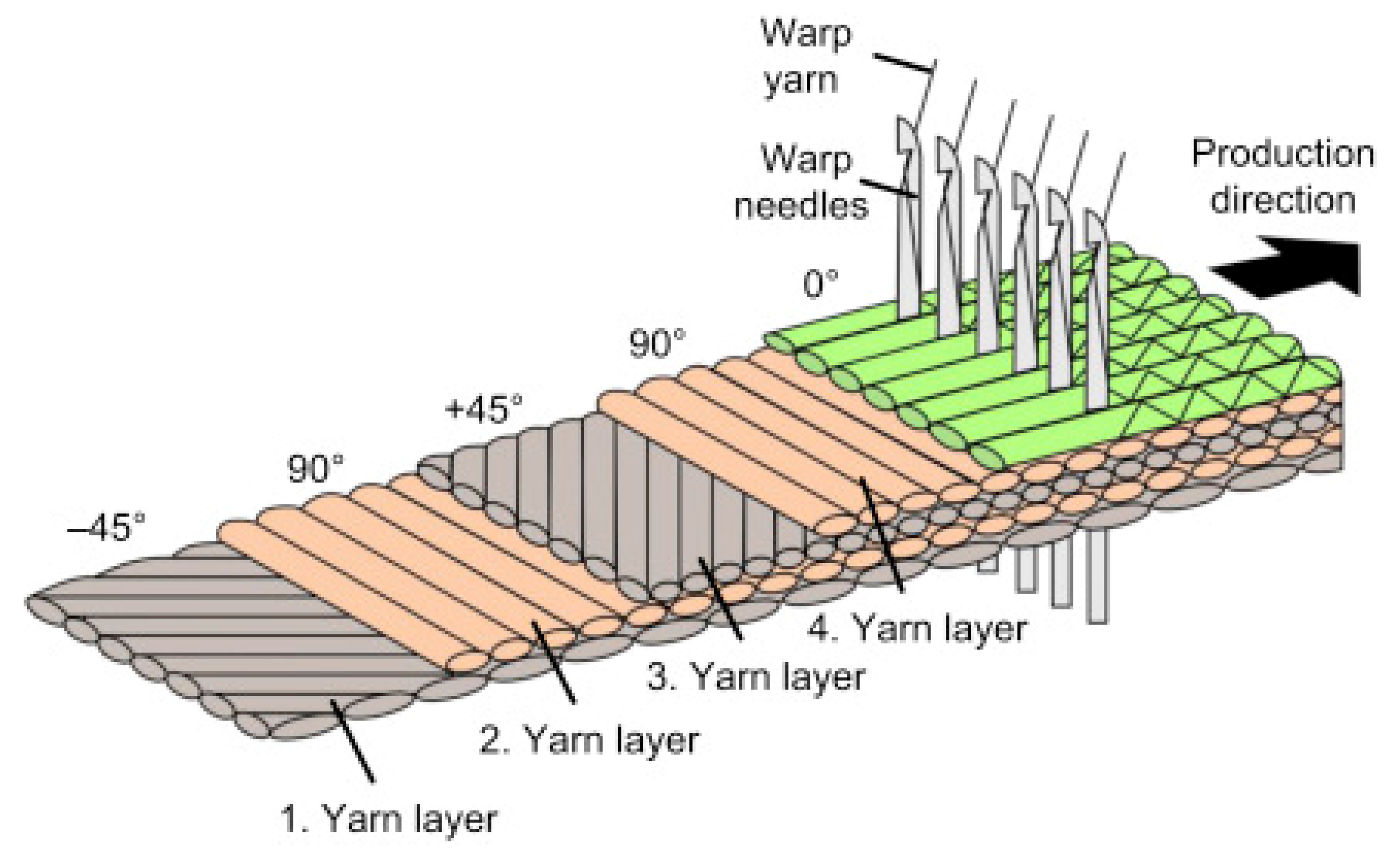
The second choice was a sheet compound of HexMC surrounding the core. The third choice was four plies of Filava Quasi Quadriaxial (FQQ) has 400 gsm, FQQ has four UD Filava fibre stitched and oriented at −45°, 90°, 45° and 0° as shown in Figure 5. The dry fabric was impregnated with an epoxy resin trade name “Resoltech 1050”.
The last choice was 4 plies of UD and one Ply of Twill 2 × 2 Filava fibres has 300 gsm Impregnated with Epoxy. The curing cycle was for 6 h at 110 °C at a ramp rate of 5 C/min under the compression pressure of 50 kN.
3. Experimental Section
3.1. Three-Point Bending Test
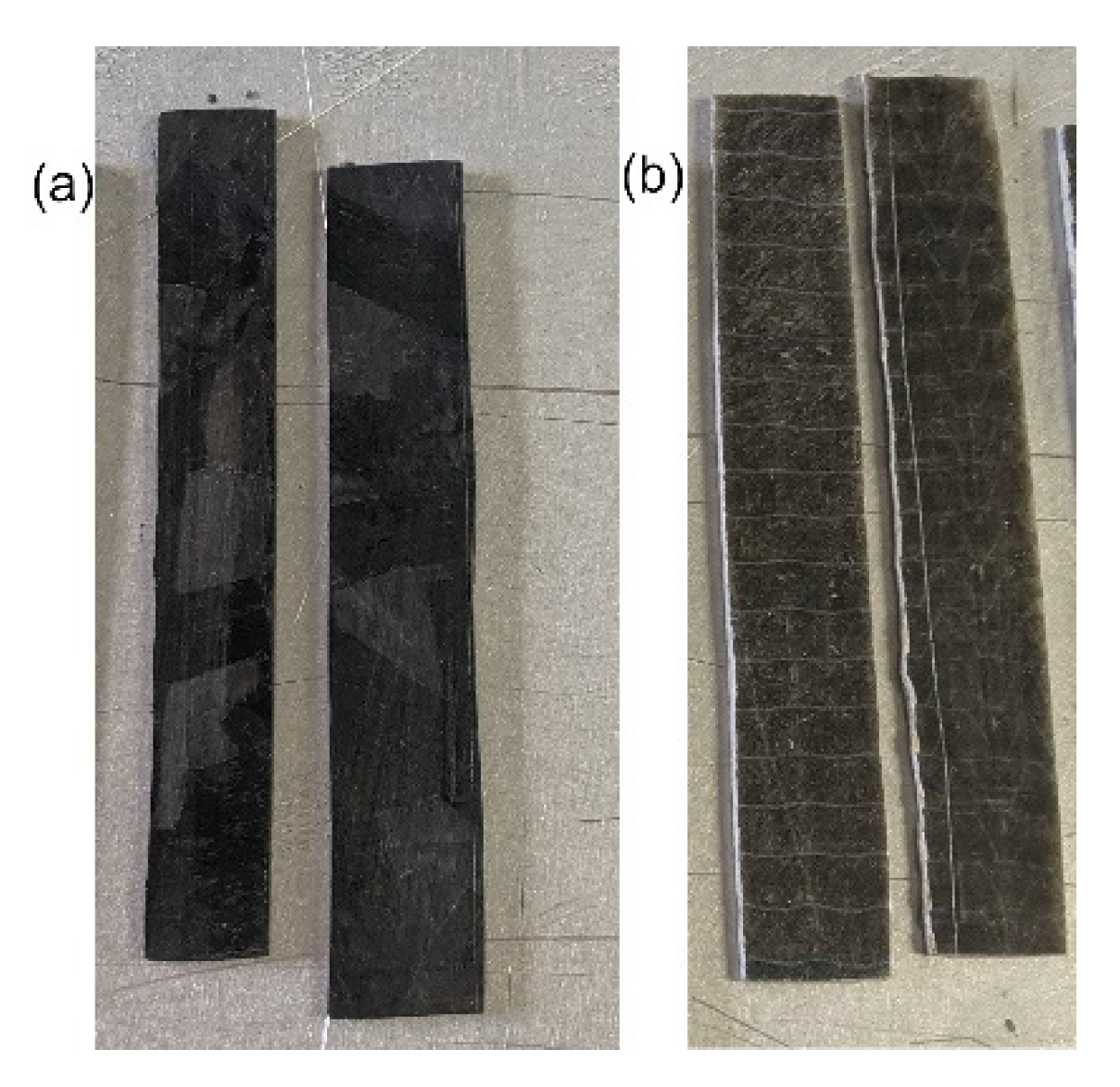
Representative samples were made from 4 plies from FQQ and 2 plies from HexMC to obtain material data input for FEA simulation, they were hot compressed at 110 °C and 50 kN to form flat specimens, such as HexMC shown in Figure 7a, Filava Quasi Quadriaxial (FQQ) in Figure 7b. Specimen dimensions are listed in Table 3, the test was performed using 20 kN Zwick Roell rig at ramp rate 1 mm/min according to BS-ISO 14125:1998.
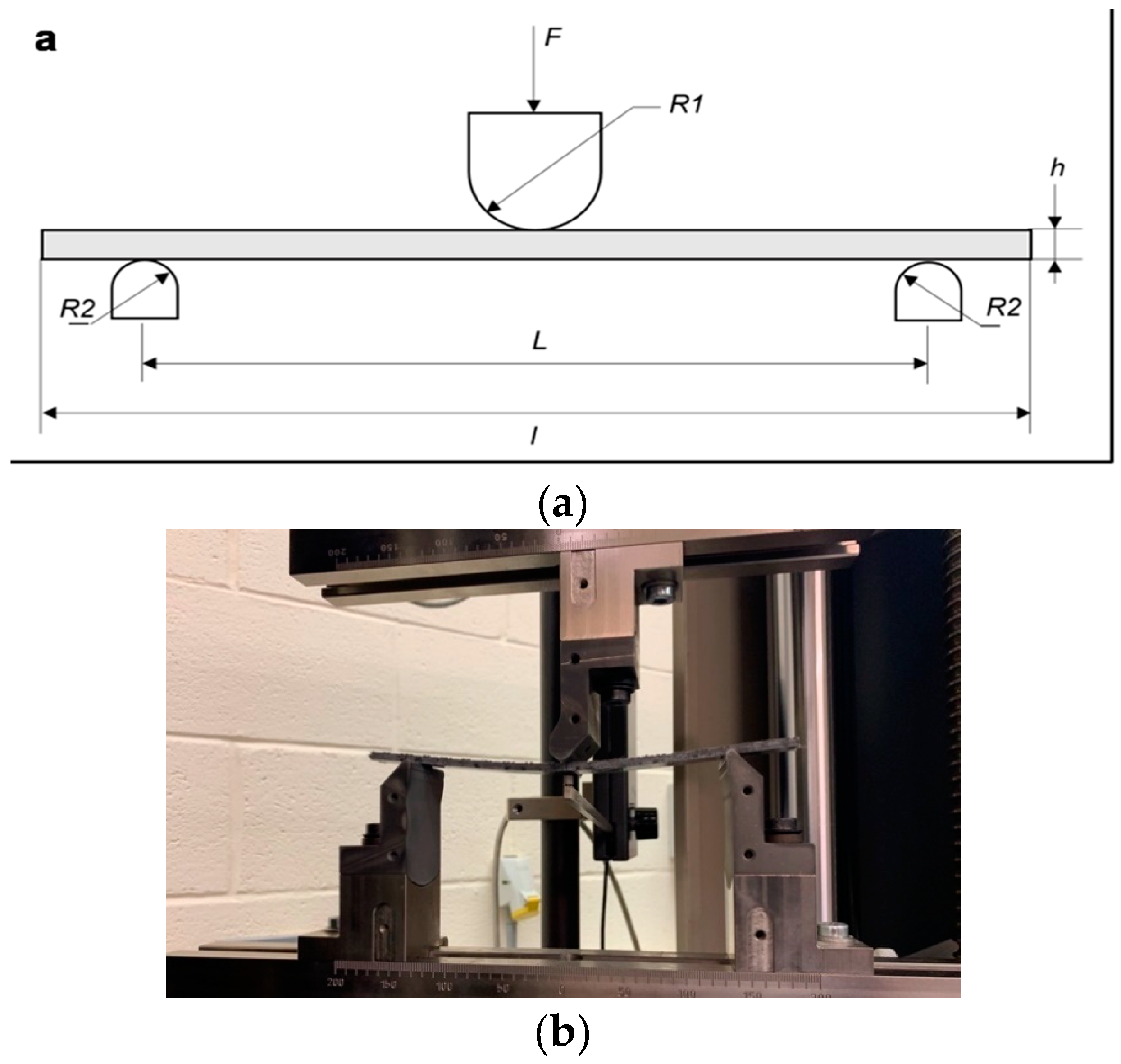
The standard specifies a support span (L) as 40 h for CFRP (class IV) category and 20 h for GFRP (class III) category. The deformation rate set to be 1 mm/min to failure using R1 (5 mm) and R2 (2 mm) fixture rollers as shown in Figure 8a. The strain was measured using an extensometer to calculate accurate flexural deflections as shown in Figure 8b.
The maximum flexural stress (σf), flexural modulus (Ef) and strain (ε) were calculated using Equations (1)–(3).
where σf: flexural stress, Ef: flexural modulus of elasticity, ε: strain, F: load (N), L: span (mm), h: thickness of the specimen, b: width of the specimen (mm) and y: deflection (mm).
3.2. Fuselage Flexural Tests
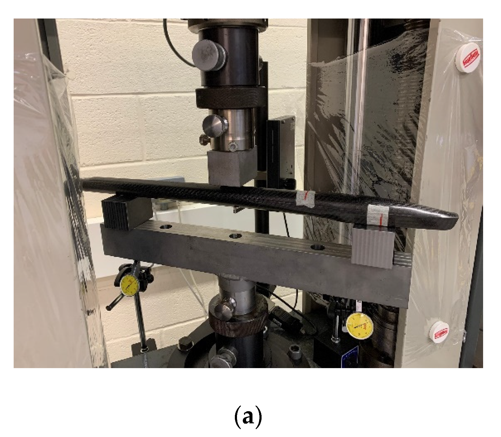
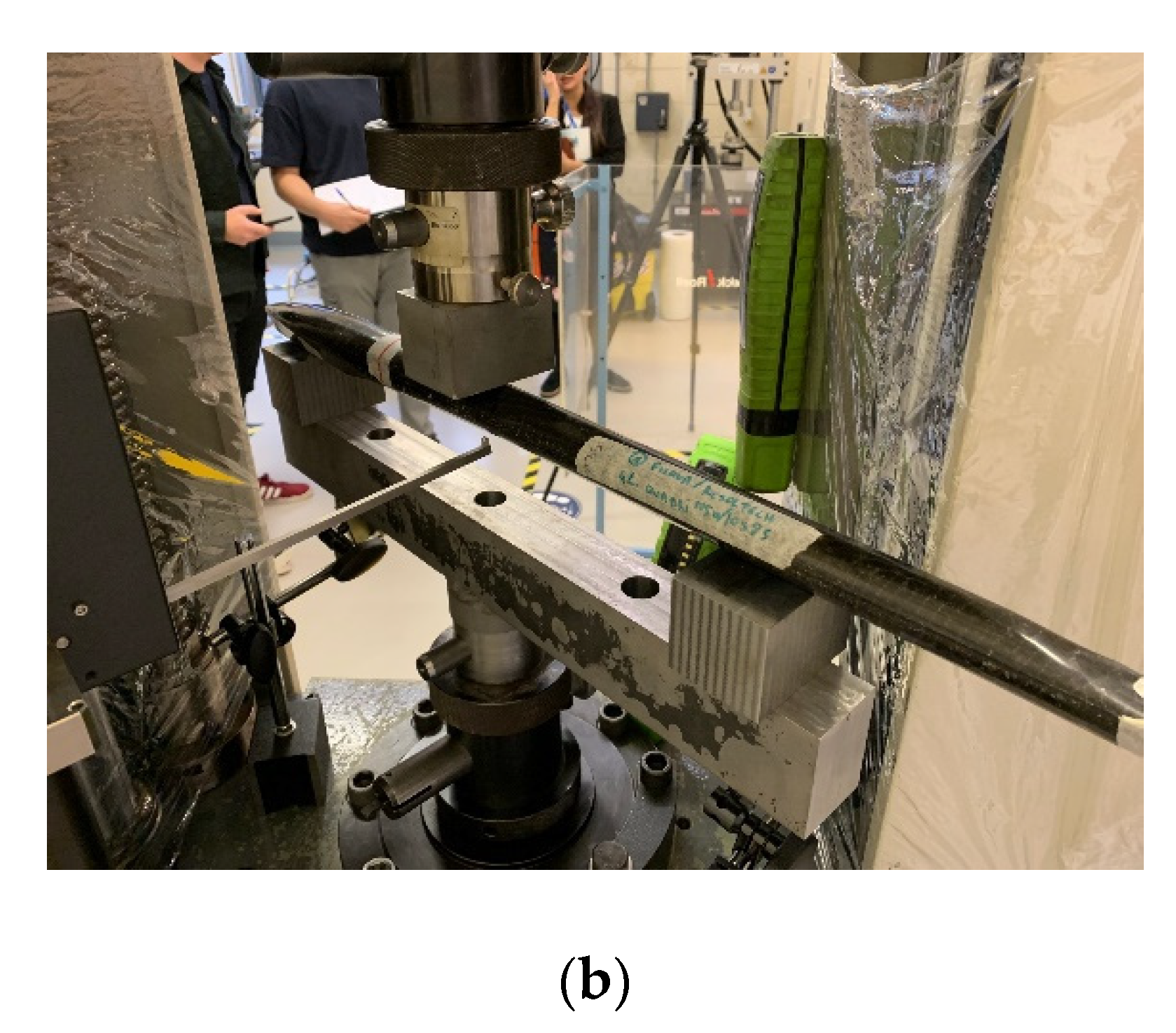
A 3-point flexural test was performed using Zwick Roell 1474 rig at a ramp rate of 1 mm/min testing rig to examine the strength of mast/wing joining points and obtain the flexural modulus and strength, as shown in Figure 9a.
Our flexural test does not follow any standard and it was made to exhibit the behaviour of the fuselages made from different composite materials. The aim is to assess the stiffness and strength of the fuselage to carry an average surfer’s weight (75 kg). Fuselages were placed on a support span of 360 mm, while stress was applied at mid-span at a ramp rate of 1 mm/min, the deflections were monitored using a digital extensometer shown in Figure 9b. The test proceeded to the failure point of the part.
3.3. FEA Simulation
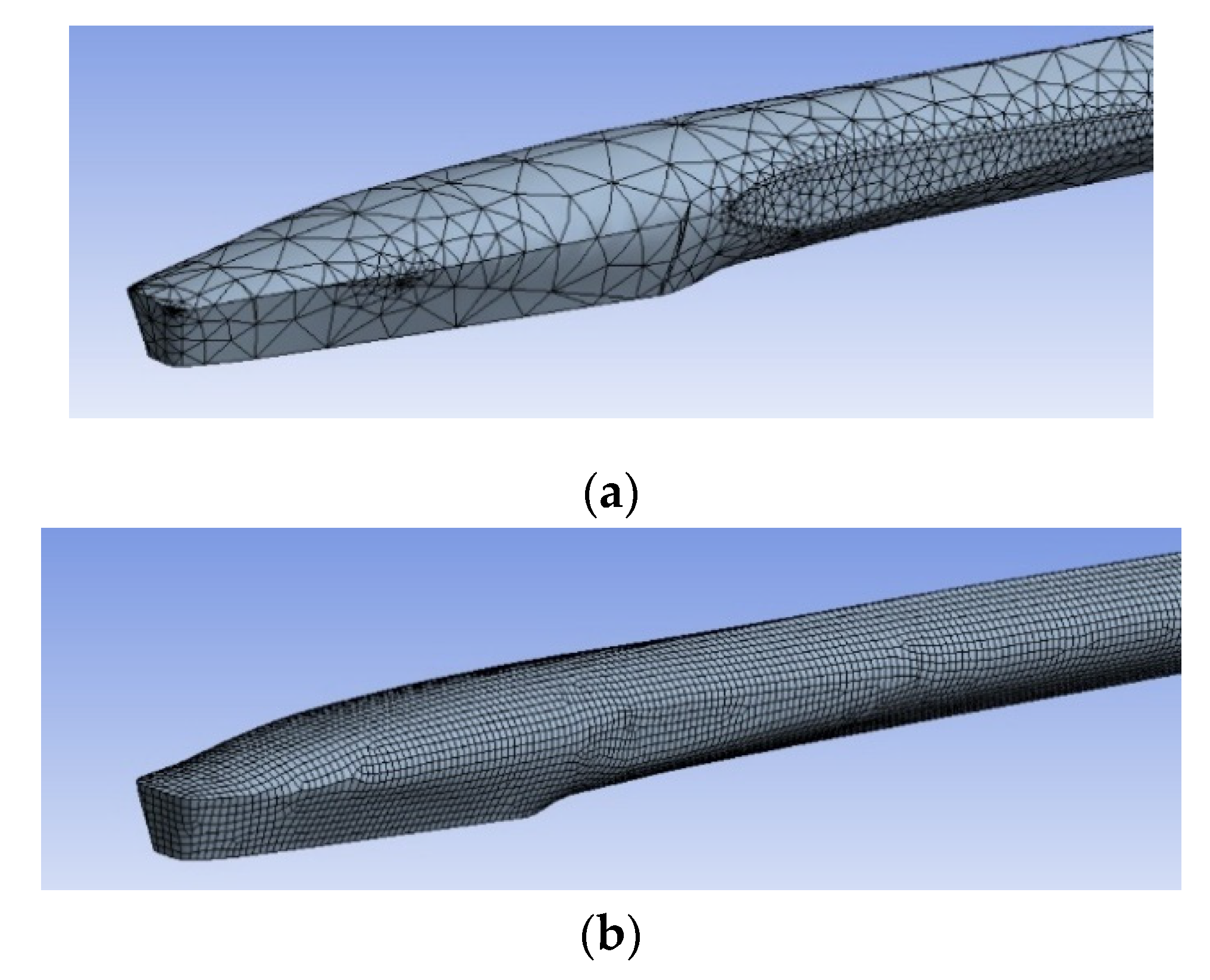
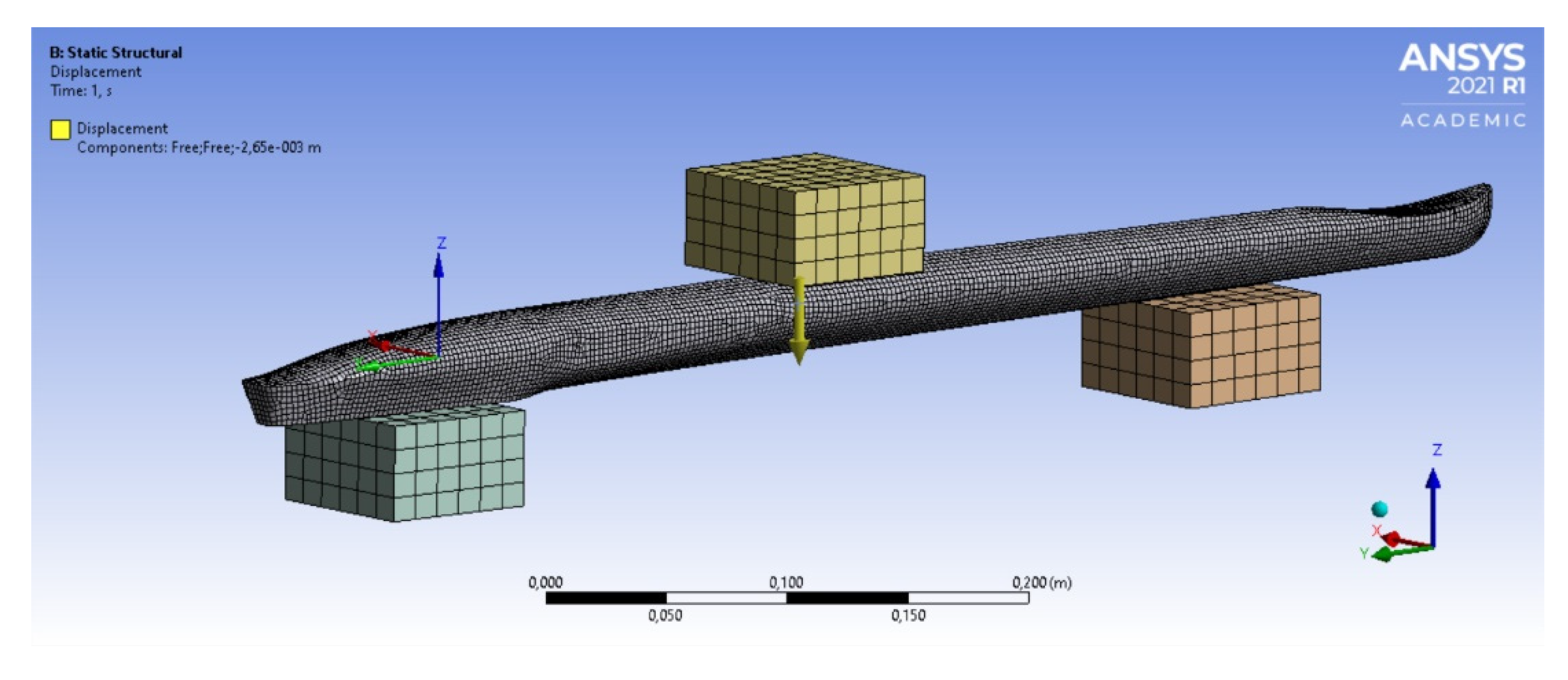
The FEA simulation was performed using the ANSYS software using the experimental work boundary condition. The meshing was made using three-dimensional cubic elements for the composite part and three-dimensional triangular elements for the foam core as shown in Figure 10a,b. A consequent difference in element size between the composite and foam parts occurs because the decision was to focus on the composite part results. Hence, less precision was allowed for the simulation of the foam part. Table 4 provides the number of elements and nodes for the two parts.
The applied force in the FEA simulation was applied in form of deflection value obtained from the flexural test have been applied in the simulation of 3-point bending (Table 5). Two bottom fixtures at span 360 mm and one probe force at the mid-span to detect the maximum force required for each deflection value. Forces have been obtained from those displacements as shown in Figure 11. Table 5 shows the displacement set for each fuselage.
4. Results
4.1. Flexural Results
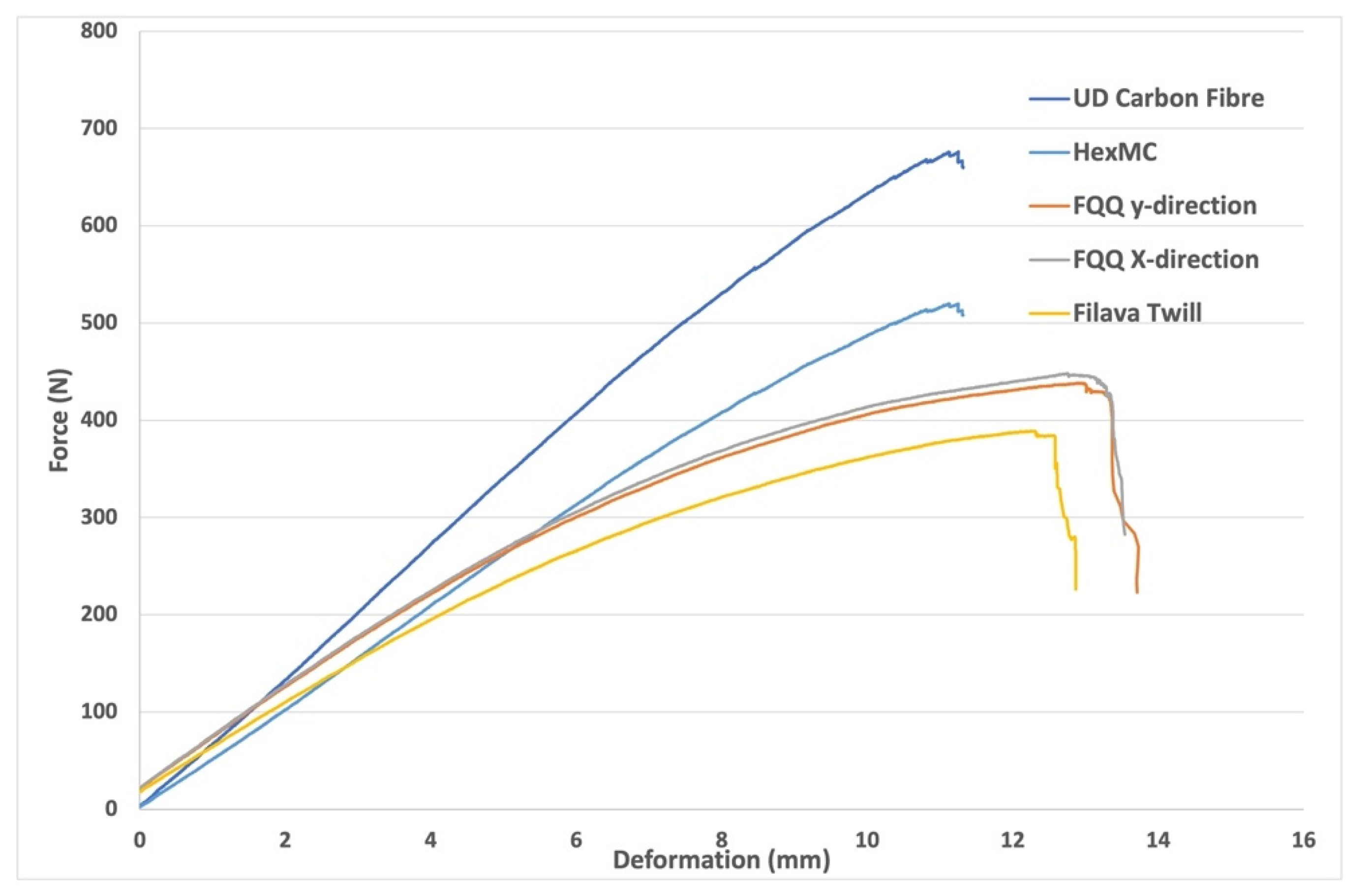
The flexural force-deflection curve for UD CFRP, HexMC, FQQ, and Filava Twill specimens are shown in Figure 12. The elastic region has been identified for both samples between 0–5 mm. Hence, the flexural modulus, strength and strain has been determined and listed in Table 6 using Equations (1)–(3). Note that FQQ has the highest flexural strain, as shown in Figure 12 and listed in Table 6. This elasticity explains the privilege of using quadriaxial orientated fibres for enhancing the flexibility in the surfboard.
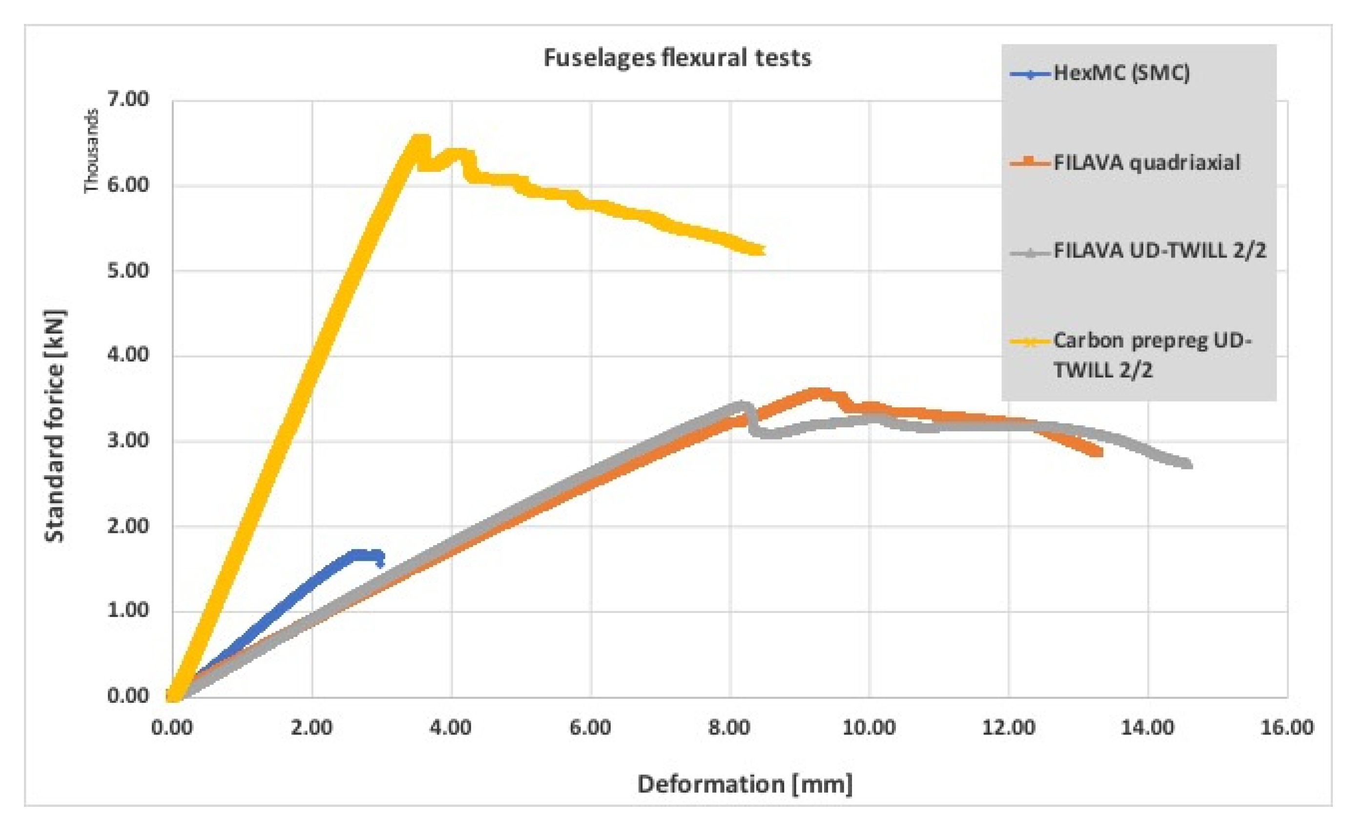
The flexural test results of the fuselages are shown in Figure 13. As expected, the CFRP-UD/Twill fuselage had the maximum flexural load (6540 N) and the HexMC sample had the lowest flexural load (1670 N). However, in terms of deflection, as expected FQQ has the maximum deflection of 9.4 mm and HexMC has the lowest deflection of 2.55 mm.
The maximum forces, deflection, stiffness, and specific stiffness are listed in Table 7. The specific stiffness has been calculated by dividing the stiffness over the mass of each fuselage to be consistent with an accurate comparison.
4.2. Simulation Results
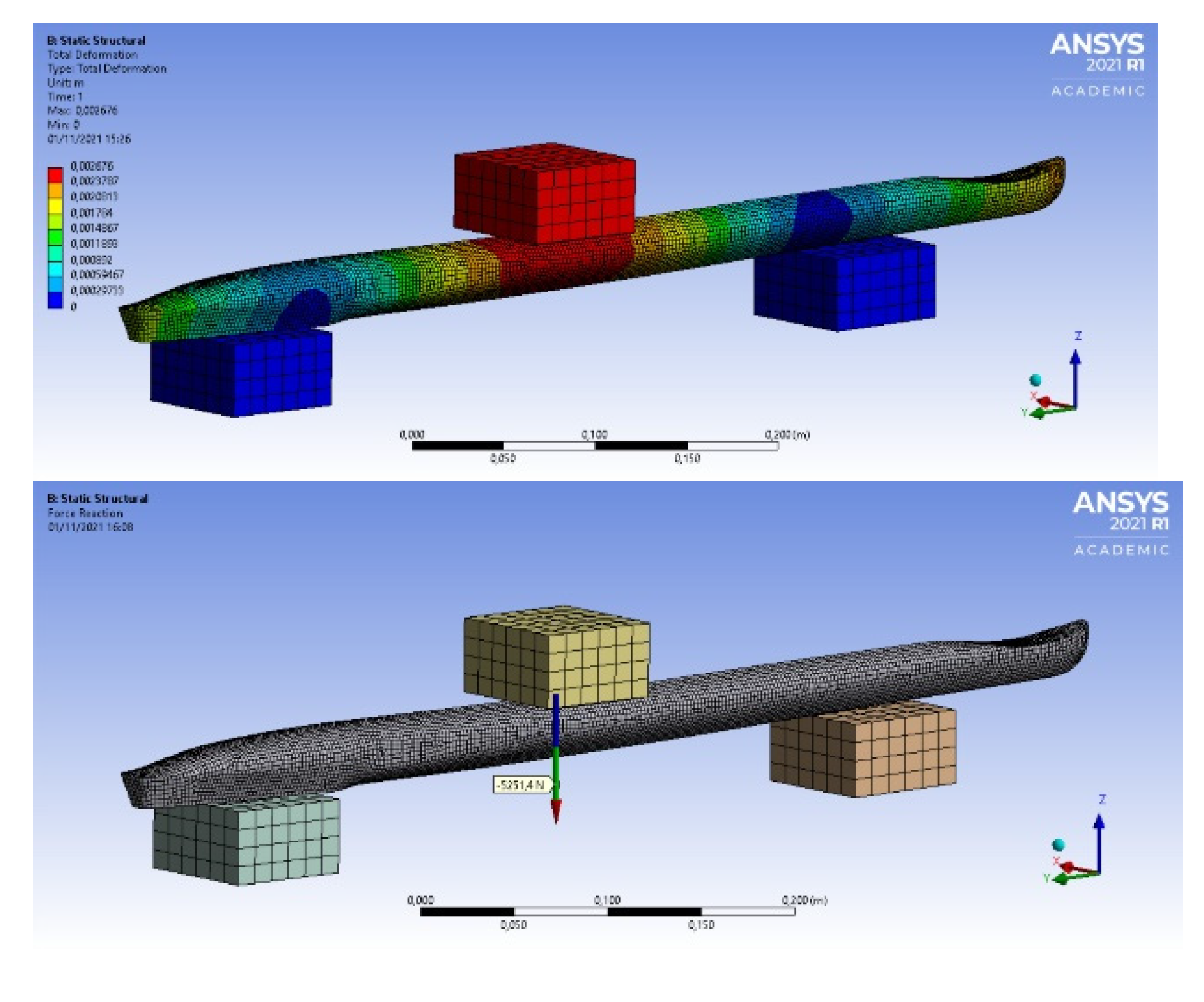
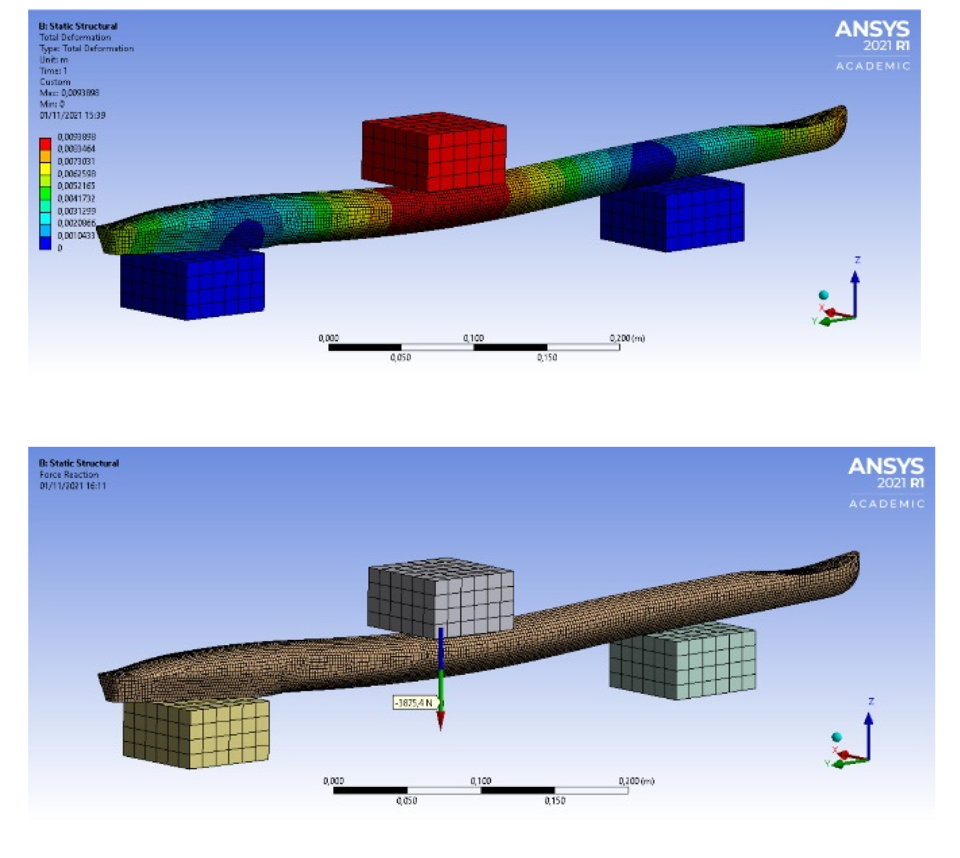
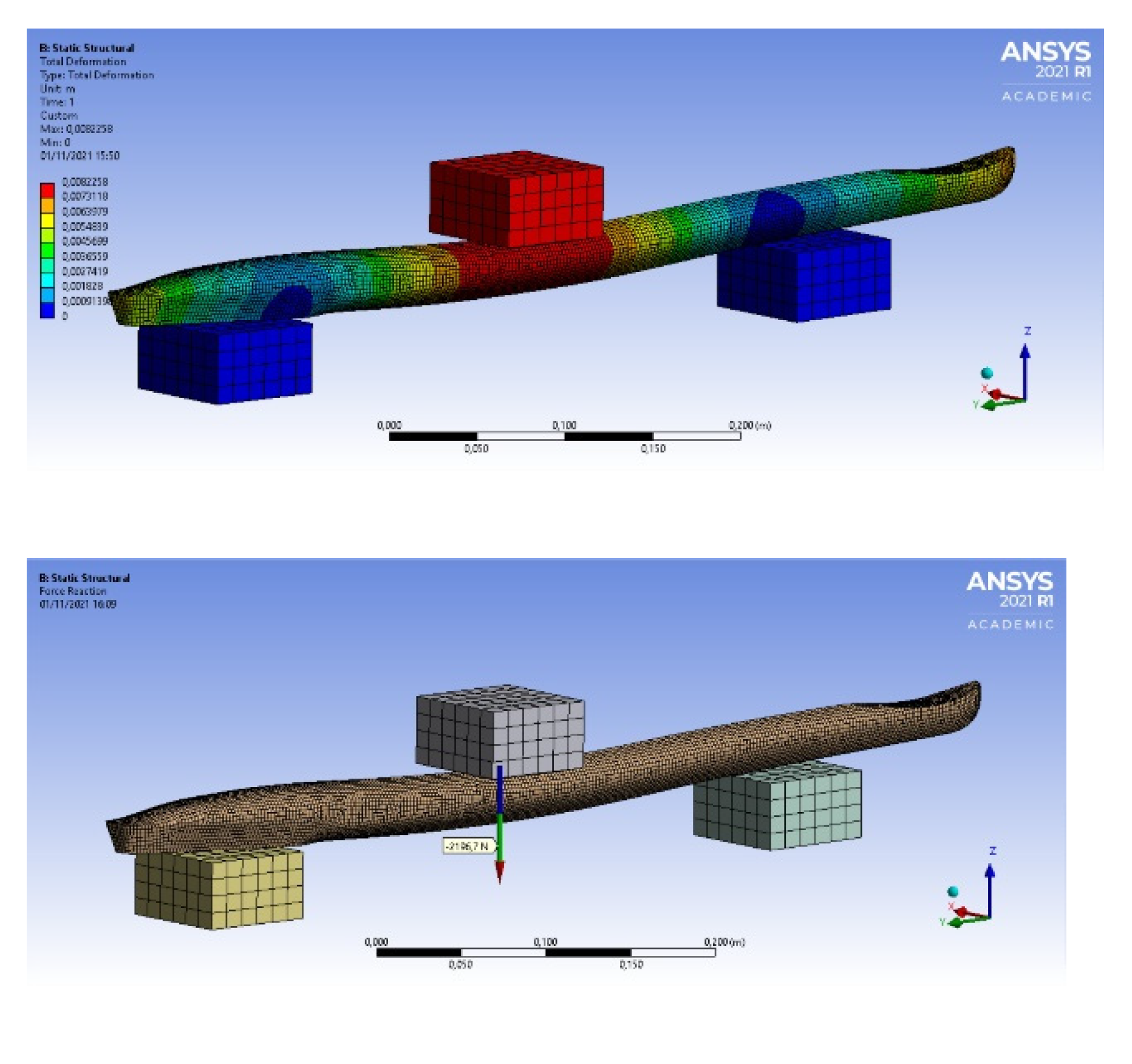
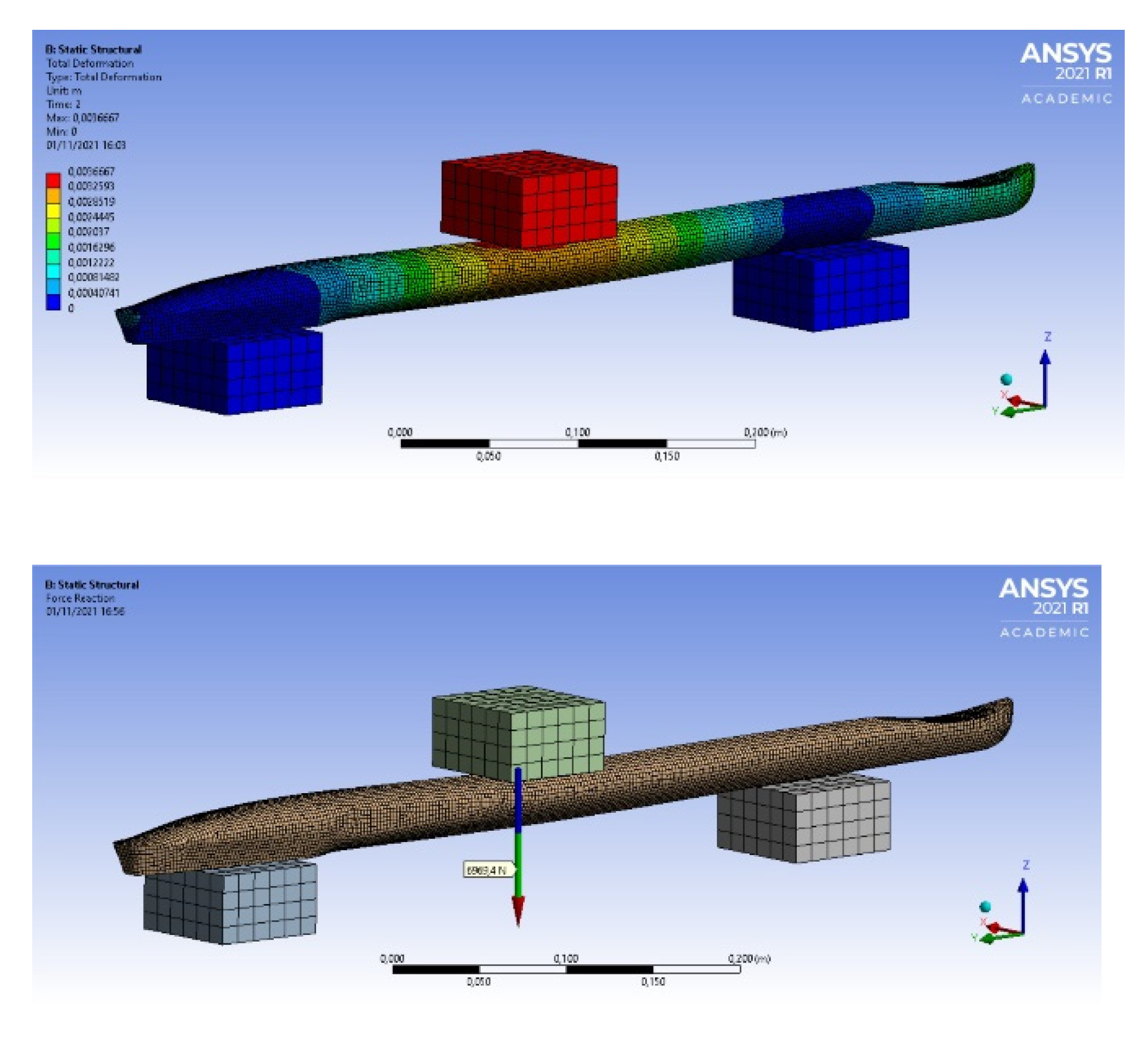
To validate the experimental results, FEA simulations were performed on four fuselages using the experimental deflections listed in Table 7 as input parameters. In the simulation configuration, the fixture geometry, support span, and location of point load were identical to the experimental set-up. The resulting load from solving the FEA model are shown in Figure 14, Figure 15, Figure 16 and Figure 17.
The summary of the outcomes is listed in Table 8, highlighting the applied deflection and the resulting forces compared to those obtained in the experimental work. The comparison between them is highlighted in the discussion section.
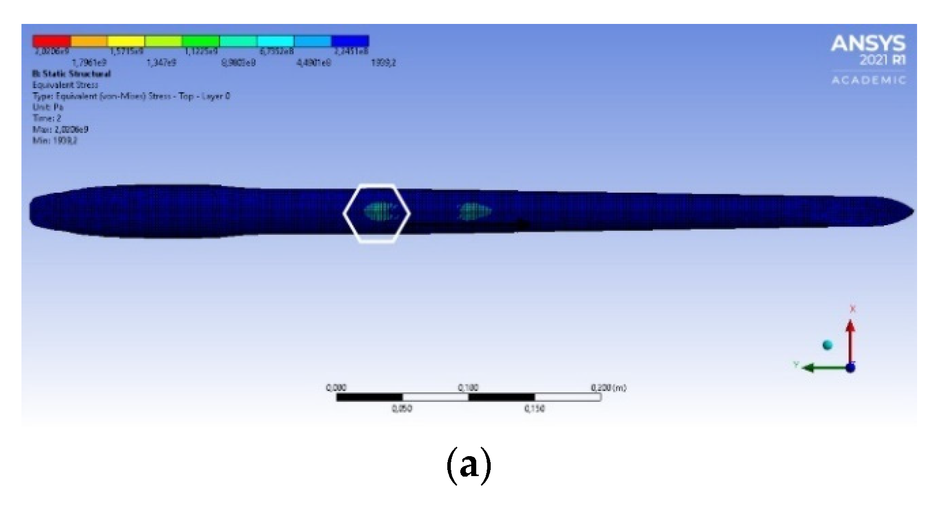
The location of maximum stress in both FEA simulation and experimental were identical, as shown in Figure 18a,b, respectively. The maximum stress will be carried out the mast that fitted into the fuselage with slide shift in location. All fuselages were failed due to the flexural compression stress located at the upper part of the fuselage. An optimised design would be required to strengthen the upper part of the fuselage by adding more material to the skin and reducing material from the tail that has the minimum stress.
4.3. Discussion
There are no official weight restrictions or size limits in a wing foil surfboard. Surfboards are designed to provide float for surfers to successfully ride waves. For heavier surfers, it is as simple as riding a bigger surfboard. The overall expectation from the results shows that all fuselages can carry 150 kg surfer weight and included a safety factor of 3 except for the HexMC fuselage. The specific stiffness of HexMC (3.80 kN/m.kg) indicates that the material can still be a good option in terms of its specific stiffness that exceeds both Filava-made fuselage. The HexMC fuselage showed lack of compression zones, leading the part to fail faster than expected. The HexMC simulation proves that the results would have been more coherent if the part were correctly manufactured by adding an equivalent weight of 300 g to ensure consistency with others. Moreover, its fast-curing time and quasi-isotropic properties are engaging factors in the production of monolithic parts.
Regarding the simulation results of the two Filava fuselages, they appeared to be matched with the experimental work with slight differences. The simulation of the Filava fuselages should be carefully interpreted when compared to others since the epoxy was manually impregnated. Resulting in inconsistence fibre volume fraction and non-uniform impregnation across the fuselage.
Generally, prepreg carbon fibres composite is the more standard material for laminating surfing fuselage, but not the optimum choice in terms of cost. Moreover, prepreg UD carbon fibre has proven to have less flexibility, hence less projection. The prepreg sheets are proven to be easy to laminate; however, difficulty in draping in corners and edges and high-rate production (curing time of 40 min) are the major concerns.
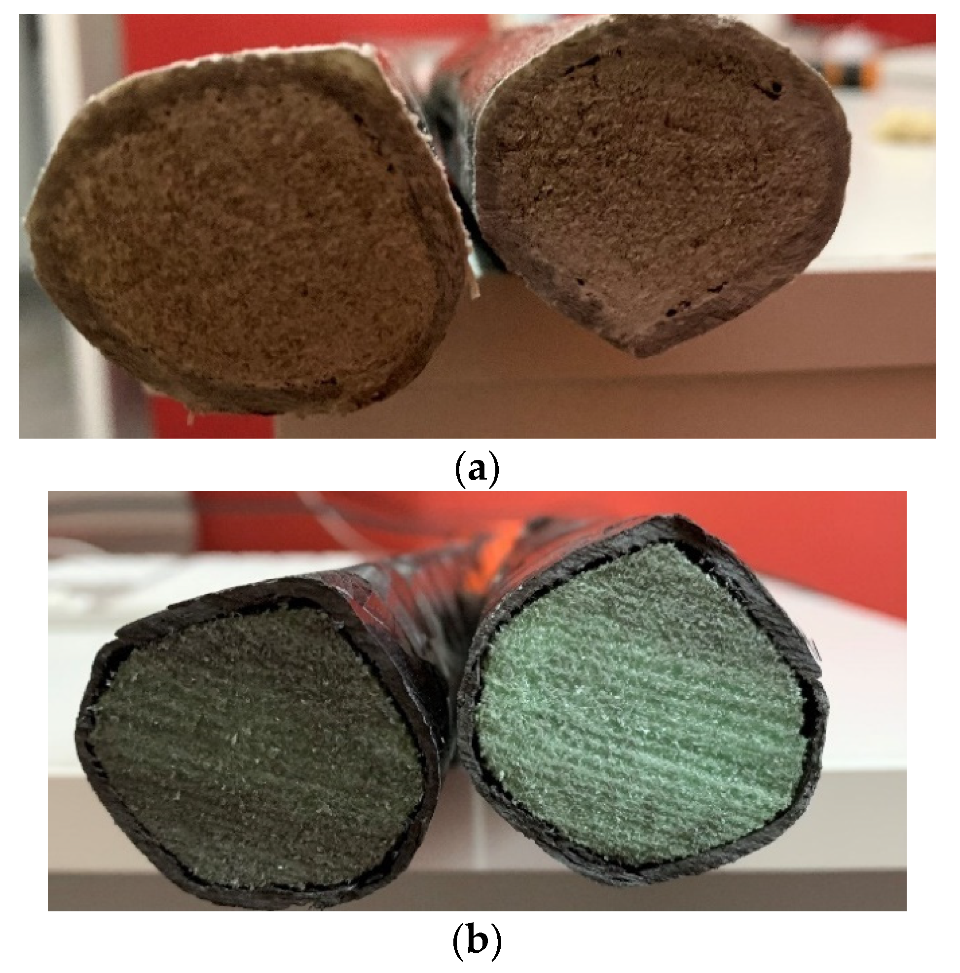
Defects and imperfection are inevitable in compression moulding; an air gap was observed between the skin and the core in HexMC, unlike in F-UD-Twill fuselages, as shown in Figure 19a,b, respectively. Lack of compression zones in HexMC were found after curing. The theoretical thickness of HexMC was set to be 2 mm in the hope to fill the gap between the core and the mould. Hence, the decision to place only one layer of HexMC. However, shrinkage happens during hot compression moulding, leading the final thickness to be less than 2 mm. The resulting air gap suggests that the mould was not packed with enough skin material. The sectional view in Figure 19b verifies our hypothesis in showing a gap between the skin and the core. Further, the total mass listed in Table 2 indicate that not enough material was applied, and it is 45% less than the prepreg CFRP fuselage. Therefore, The HexMC fuselage would have needed at least 130 g to avoid shrinkage during compression moulding.
Another source of error source is the non-uniform circumferential geometry of the fuselage due to hand lamination. The experimental results become inaccurate due to inaccuracy in second moment of inertia. Furthermore, the set-up of fibre/resin volume fraction in the FEA simulation was based on the assumption of fibre volume fraction consistency, which makes it difficult to find a suitable solving model [3].
The largest deformation (9.4 mm) was found in FQQ fuselage, indicating a high projection rate during surfing, which makes the best option, to the best of our knowledge. The FEA simulation shows a good agreement with experimental results, hence the results can be validated apart the one from the HexMC fuselage. The flexural testing is deemed to be a preliminary assessment for choosing the best materials for a prototype demonstration; however, a fatigue resistance will be required in the future to examine the suitability of each material for mass production on large scale.
5. Conclusions
This study aimed to conduct a comparative mechanical behaviour of fuselage for wing foil through flexural testing and has been validated using FEA simulation. As HexMC fuselage was cured for 8 min at 120 °C under a hydraulic press. It showed a promising short curing cycle and moderate specific stiffness. All fuselages were able to carry a nominal surfer weight (max 150 kg), but more important are the potential reactive flex seen in quadriaxial Filava fibre fuselage.
Despite the lengthy process of impregnation and lamination of both Filava fibres fuselage, the FEA simulation was found to be in line with the flexural results. Dry fabric impregnation requires more time than prepreg lamination, hence our future work will be aimed at exploring the option of making prepreg Filava fibre composite. In addition, future production of uniform parts can be projected toward using pressurised rubber bladder instead of foam. This will require a tool pattern change and a customized rubber bladder. Nonetheless, the high reactive flex properties in quadriaxial woven Filava fibre indicate great potential use in sports applications.
Author Contributions
Conceptualization, A.M.F.C. and K.B.; methodology, A.M.F.C.; software, A.M.F.C.; validation, A.M.F.C. and K.B.; formal analysis, A.M.F.C.; investigation, A.M.F.C.; resources, K.B.; data curation, K.B.; writing—original draft preparation, A.M.F.C.; writing—review and editing, K.B.; visualization, K.B.; supervision, K.B.; project administration, A.M.F.C. All authors have read and agreed to the published version of the manuscript.
Funding
This research received no external funding.
Institutional Review Board Statement
Not Applicable.
Informed Consent Statement
Not Applicable.
Data Availability Statement
The Authors can provide data upon formal request to the University of Wolverhampton.
Acknowledgments
The authors would like to acknowledge the funding provided by MDPI for publishing this article in the Journal of composite science and the compnay Isomatex/Belgium for providing samples from various woven Filava fabrics.
Conflicts of Interest
The authors declare that there is no conflict of interest.
References
- Hexcel. HexPly Prepreg, FGU017c. 2013, p. 35. Available online: https://www.hexcel.com/user_area/content_media/raw/Prepreg_Technology.pdf (accessed on 11 November 2021).
- Meredith, J.; Bilson, E.; Powe, R.; Collings, E.; Kirwan, K. A performance versus cost analysis of prepreg carbon fibre epoxy energy absorption structures. Compos. Struct. 2015, 124, 206–213. [Google Scholar] [CrossRef] [Green Version]
- Bari, K.; Loganathan, T.G. The Performance of Filava-Polysiloxane, Silres® H62C Composite in High Temperature Application. J. Compos. Sci. 2021, 5, 144. [Google Scholar] [CrossRef]
- Sakellariou, K.; Rana, Z.A.; Jenkins, K.W. Optimisation of the surfboard fin shape using computational fluid dynamics and genetic algorithms. Proc. Inst. Mech. Eng. Part P J. Sports Eng. Technol. 2017, 231, 344–354. [Google Scholar] [CrossRef]
- Callister, W.D.; Rethwisch, D.G. Materials Science and Engineering, 8th ed.; John Wiley and Sons: Hoboken, NJ, USA, 2019. [Google Scholar]
- Hexcel. Airframe. 2011. Available online: https://www.airframer.com/news_story.html?release=14629 (accessed on 11 November 2021).
- Feraboli, P.; Peitso, E.; Cleveland, T.; Stickler, P.B. Modulus Measurement for Prepreg-based Discontinuous Carbon Fiber/Epoxy Systems. J. Compos. Mater. 2009, 43, 1947–1965. [Google Scholar] [CrossRef]
- Evans, A.D.; Qian, C.C.; Turner, T.A.; Harper, L.T.; Warrior, N.A. Flow characteristics of carbon fibre moulding compounds. Compos. Part A Appl. Sci. Manuf. 2016, 90, 1–12. [Google Scholar] [CrossRef]
- Dhand, V.; Mittal, G.; Rhee, K.Y.; Park, S.-J.; Hui, D. A short review on basalt fiber reinforced polymer composites. Compos. Part B Eng. 2015, 73, 166–180. [Google Scholar] [CrossRef]
- Voss, B. Filava Fibre Material Data Sheet. 2019. Available online: www.isomatex.com (accessed on 11 November 2021).
Figure 1.
(a) Image shows a short hydro foil surfboard, (b) Illustration of component in hydro foil surfboard.
Figure 1.
(a) Image shows a short hydro foil surfboard, (b) Illustration of component in hydro foil surfboard.

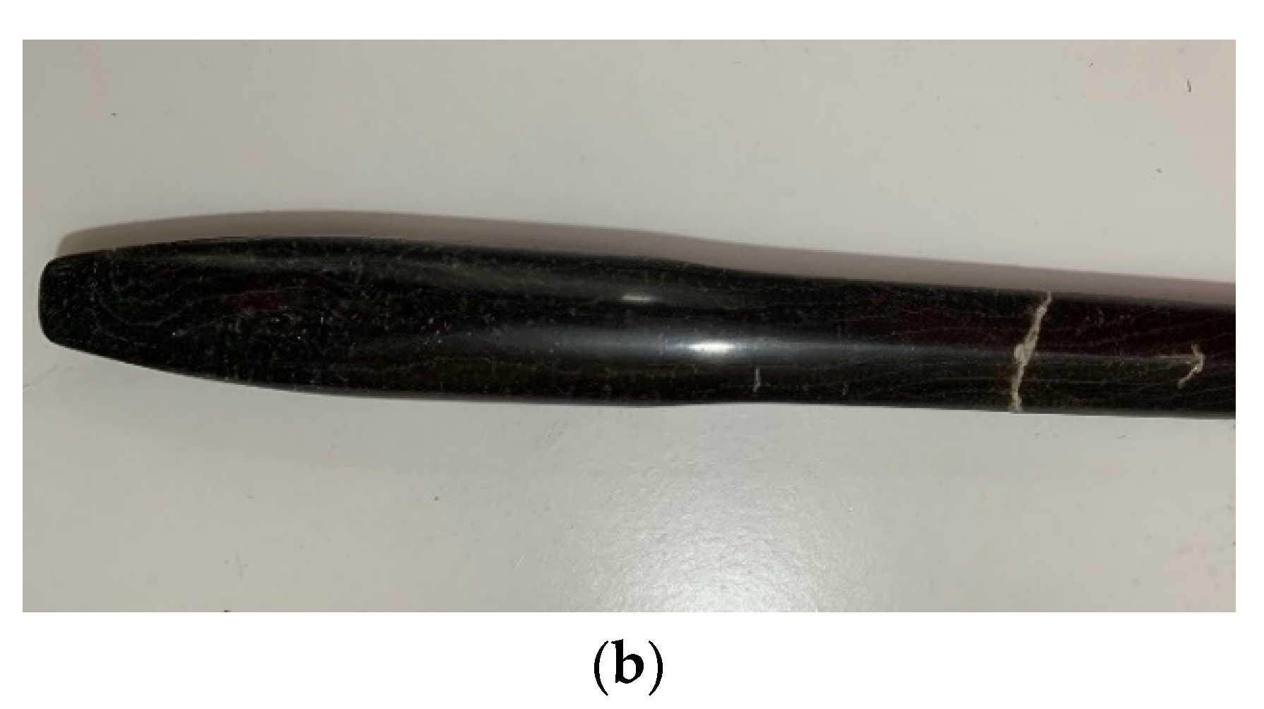
Figure 2.
Kiwi Model fuselage shows titanium front section, CFRF mid-section, and GFRP tail section.
Figure 2.
Kiwi Model fuselage shows titanium front section, CFRF mid-section, and GFRP tail section.

Figure 3.
(a) 2D sketch of the fuselage, (b) Physical machined mould shows two female cavity.

Figure 4.
(a) PVC core located inside the mould, (b) Prepreg sheet laminated the core and fitted inside the mould.
Figure 4.
(a) PVC core located inside the mould, (b) Prepreg sheet laminated the core and fitted inside the mould.


Figure 5.
Image showing the fibre orientation and warp yarn in quasi quadriaxial fabric.

Figure 6.
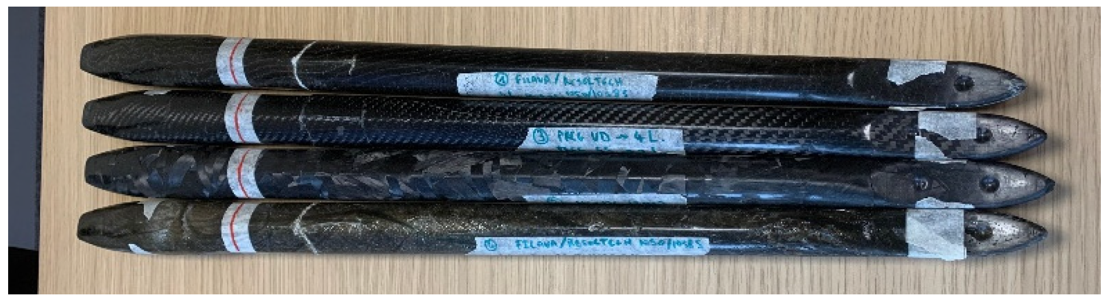
Image showing the end products of the fuselage.

Figure 7.
(a) flat HexMC specimens, (b) FQQ specimens.

Figure 8.
(a) 2D sketch of 3-point flexural test, (b) Physical 3-point flexural illustration according to BS-ISO 14125:1998. Support span 20 h mm (class III) and 40 h mm (class IV).
Figure 8.
(a) 2D sketch of 3-point flexural test, (b) Physical 3-point flexural illustration according to BS-ISO 14125:1998. Support span 20 h mm (class III) and 40 h mm (class IV).

Figure 9.
Flexural test set for the fuselage (a) CFRP fuselage, (b) QQF Fuselage.


Figure 10.
(a) Core mesh size, (b) Skin mesh size.

Figure 11.
Boundary conditions from the flexural tests.

Figure 12.
Flexural plot of all four samples according to BS-ISO:14125.

Figure 13.
Flexural results of the fuselages.

Figure 14.
HexMC (displacement 2.55 mm, resulting force 5251.4 N).

Figure 15.
Filava quadriaxial (displacement 9.40 mm, resulting force 3875 N).

Figure 16.
Filava UD/Twill (displacement 8.23 mm resulting force 2197 N).

Figure 17.
CFRP UD/Twill (displacement 3.61, resulting force 6936 N).

Figure 18.
(a) Displacement and (b) equivalent stress of CFRP-UD/Twill fuselage.


Figure 19.
A cut into cross section of the fuselage (a) FQQ interface (b) HexMC fuselage.


Table 1.
Mechanical properties of the potential materials [5].
Table 1.
Mechanical properties of the potential materials [5].
| Material | Tensile Properties | Poisson’s Ratio | Density (g/cm3) | Cost £/kg | |
|---|---|---|---|---|---|
| Strength (MPa) | Modulus (GPa) | ||||
| Titanium (grade 2) | 344 | 105 | 0.37 | 4.51 | 50.5 |
| CFRP-UD-Epoxy | 2000 | 130 | 0.25 | 1.53 | 16.35 |
| HexMC-Epoxy | 300 | 38 | 0.30 | 1.55 | 12.35 |
| Filava UD-Epoxy | 1700 | 95 | 0.24 | 2.6 | 15.5 |
Table 2.
Mass of the fuselages.
| CFRP-UD | HexMC | FQQ | F-UD/T | |
|---|---|---|---|---|
| Total weight (g) | 307 | 171.5 | 255.5 | 279 |
| Core weight (g) | 29.5 | 29.7 | 29.3 | 23.6 |
Table 3.
Specimen dimensions.
| Specimen | Length (l), mm | Width (b), mm | Thickness (h), mm | Support Span |
|---|---|---|---|---|
| HexMC | 100 | 15.4 | 2.0 | 40 h (80 mm) |
| FQQ | 100 | 15.0 | 1.98 | 20 h (39 mm) |
| Filava Twill | 100 | 15.1 | 2.1 | 20 h (42.0 mm) |
| Carbon UD | 100 | 15.0 | 2.0 | 40 h (80 mm) |
Table 4.
Meshing properties of the simulation model.
| Fuselage Part | Element Type | Number of Elements | Number of Nodes |
|---|---|---|---|
| Composite part | Cubic | 10,474 | 10,444 |
| Foam core | Triangular | 10,751 | 18,179 |
Table 5.
Deflection values.
| Specimen | Displacement Set (mm) |
|---|---|
| HexMC | 2.55 |
| FQQ | 9.40 |
| F-UD/Twill | 8.23 |
| CFRP-UD/Twill | 3.61 |
Table 6.
Flexural properties and elongation of all samples.
| Specimen | Maximum Load (N) | Maximum Deflection (mm) | Ef (GPa) | σ(MPa) | ε (%) |
|---|---|---|---|---|---|
| CFRP-UD | 680 | 10.55 | 68.12 | 1224 | 1.98 |
| HexMC | 505 | 10.40 | 51.74 | 810 | 1.95 |
| FQQ | 450 | 13.51 | 33.75 | 675 | 4.5 |
| Filava Twill | 380 | 12.20 | 32.4 | 517 | 4.27 |
Table 7.
Maximum load, deflection and stiffness of four fuselages.
| Specimen | Maximum Load (N) | Maximum Deflection (mm) | Fuselage Mass (g) | Stiffness (MN/m) | Specific Stiffness (MN/m.kg) |
|---|---|---|---|---|---|
| HexMC | 1670 | 2.55 | 171.5 | 0.655 | 3.8 |
| FQQ | 3530 | 9.40 | 255.5 | 0.37 | 1.44 |
| F-UD/Twill | 3410 | 8.23 | 279 | 0.41 | 1.47 |
| CFRP-UD/Twill | 6540 | 3.61 | 307 | 1.81 | 5.90 |
Table 8.
FEA simulation values showing mid-span deflection and resulting loads.
| Specimen | Deflection (mm) | FEA Load (N) | Experiment Load (N) |
|---|---|---|---|
| HexMC | 2.55 | 5251 | 1670 |
| FQQ | 9.40 | 3875 | 3530 |
| F-UD/Twill | 8.23 | 2197 | 3410 |
| CFRP-UD/Twill | 3.61 | 6936 | 6540 |
Publisher’s Note: MDPI stays neutral with regard to jurisdictional claims in published maps and institutional affiliations. |
© 2021 by the authors. Licensee MDPI, Basel, Switzerland. This article is an open access article distributed under the terms and conditions of the Creative Commons Attribution (CC BY) license (https://creativecommons.org/licenses/by/4.0/).
Share and Cite
MDPI and ACS Style
Fat Cheung, A.M.; Bari, K. Novel Reactive Flex Configuration in Kiwi Wing Foil Surfboard. J. Compos. Sci. 2022, 6, 6. https://0-doi-org.brum.beds.ac.uk/10.3390/jcs6010006
AMA Style
Fat Cheung AM, Bari K. Novel Reactive Flex Configuration in Kiwi Wing Foil Surfboard. Journal of Composites Science. 2022; 6(1):6. https://0-doi-org.brum.beds.ac.uk/10.3390/jcs6010006
Chicago/Turabian StyleFat Cheung, Adrien M., and Klaudio Bari. 2022. "Novel Reactive Flex Configuration in Kiwi Wing Foil Surfboard" Journal of Composites Science 6, no. 1: 6. https://0-doi-org.brum.beds.ac.uk/10.3390/jcs6010006