Article

Thermoelectric Performance of Polypropylene/Carbon Nanotube/Ionic Liquid Composites and Its Dependence on Electron Beam Irradiation

1
Leibniz-Institut für Polymerforschung Dresden e.V. (IPF), Hohe Str. 6, 01069 Dresden, Germany
2
Institut für Werkstoffwissenschaft, Fakultät Maschinenwesen, Technische Universität Dresden, Helmholtzstr. 10, 01069 Dresden, Germany
*
Author to whom correspondence should be addressed.
Present address: Institut für Mechanische Verfahrenstechnik und Aufbereitungstechnik, Fakultät für Maschinenbau, Verfahrens- und Energietechnik, Technische Universität Bergakademie Freiberg, Agricolastr. 1, 09599 Freiberg, Germany.
Submission received: 17 December 2021 / Revised: 5 January 2022 / Accepted: 7 January 2022 / Published: 11 January 2022
(This article belongs to the Special Issue Feature Papers in Journal of Composites Science in 2021)

Abstract

:
The thermoelectric behavior of polypropylene (PP) based nanocomposites containing single walled carbon nanotubes (SWCNTs) and five kinds of ionic liquids (Ils) dependent on composite composition and electron beam irradiation (EB) was studied. Therefore, several samples were melt-mixed in a micro compounder, while five Ils with sufficiently different anions and/or cations were incorporated into the PP/SWCNT composites followed by an EB treatment for selected composites. Extensive investigations were carried out considering the electrical, thermal, mechanical, rheological, morphological and, most significantly, thermoelectric properties. It was found that it is possible to prepare n-type melt-mixed polymer composites from p-type commercial SWCNTs with relatively high Seebeck coefficients when adding four of the selected Ils. The highest Seebeck coefficients achieved in this study were +49.3 µV/K (PP/2 wt.% SWCNT) for p-type composites and −27.6 µV/K (PP/2 wt.% SWCNT/4 wt.% IL type AMIM Cl) for n-type composites. Generally, the type of IL is decisive whether p- or n-type thermoelectric behavior is achieved. After IL addition higher volume conductivity could be reached. Electron beam treatment of PP/SWCNT leads to increased values of the Seebeck coefficient, whereas the EB treated sample with IL (AMIM Cl) shows a less negative Seebeck coefficient value.

1. Introduction

In connection with the efforts for green energy production, an important task in present research is the development of thermoelectric materials which, for example, convert waste heat into electrical energy by utilizing the thermoelectric effect (TE), called the Seebeck effect. Such conversion can be achieved by applying electrically conductive polymer composites (CPCs) filled with different kinds of carbon based materials, such as carbon nanotubes (CNTs), expanded graphite (EG) or graphite nanoplatelets (GNPs) [1,2]. Advantages of polymer-based TE-materials over the typically used rare earth-based materials, such as bismuth telluride, are on the one hand their cost efficiency and availability, and on the other hand the easy processability and special material proper-ties, such as intrinsically low thermal conductivity and low density of polymer composites.
The most relevant value for quantifying the thermoelectric behavior is defined as the Seebeck coefficient (S; S-value), which is calculated as the ratio between the generated thermovoltage and applied temperature difference. Thereby a positive S-value describes p-type character (electron-withdrawing) and a negative S-value n-type character (electron-donating) of a material. Two other important parameters for quantifying the TE-performance are the power factor (PF) and the figure of merit (ZT). For calculating these characteristic values of PF and ZT, the following Equations (1) and (2) are used, where S is the Seebeck coefficient, σ the volume conductivity, T the temperature, and κ the thermal conductivity of the used material:
PF = S2 · σ
ZT = PF · T/κ
One of the first studies on melt-mixed polymer nanocomposites by Antar et al. characterized the TE performance of PLA with multi-walled CNTs (MWCNTs) and the highest S-value found was 17 µV/K at 32 vol.% EG loading, whereas the highest PF was found to be 9.6 × 10⁻² µW/mK2 at a loading of 18 vol.% MWCNTs [3]. In general, commercial CNTs: have a positive S-value (p-type) [4] and composites made from them are dominated by the behavior of CNTs, resulting in positive values as well. Sun et al. [5] reported for PVDF/2 wt.% and 5 wt.% MWCNT (type Nanocyl™ NC7000) composites a Seebeck coefficient of 10 µV/K and for PVDF with 5 to 15 vol% GNP S-values of around 25 µV/K.
Melt-mixed composites of polypropylene (PP) and CNTs were studied in detail by Luo et al. [6,7,8,9]. Thereby PP composites containing SWCNTs of the type Tuball™, which are used in this study as well, showed S-values between 25 and 34 µV/K at 0.8–6.0 wt.% loading. The highest power factor achieved was 0.66 µW/mK2 (4 wt.% SWCNT) [9]. Copper oxide (CuO) as an additional additive resulted in S-values of 37 µV/K and power factors of 0.02 µW/m·K2 [6]. Further, the addition of 2 wt% of an ionic liquid (IL) to a PP composite with 2 wt.% SWCNTs led to an increase in the Seebeck coefficient from 43 µV/K to 63 µV/K and of the power factor from 0.12 µW/m·K2 to 0.26 µW/m·K2 [7]. Moreover, Luo et al. described a way to generate stable PP/CNT-based n-type materials by adding polyethylene glycol (PEG) [6] or polyoxyethylene 20 cetyl ether (Brij58®) [8]. At 2 wt.% SWCNT loading, S-values of −56.6 µV/K (5 wt.% CuO + 10 wt.% PEG) and −38 µV/K (4 wt.% Brij58®) were measured.
An additional way to steer the thermoelectric behavior is the doping of CNTs, which can be achieved using different treatments [10,11,12,13] and dopants such as boron or nitrogen [14]. Thereby, always positive S-values (p-type) were obtained for composites with different polymer matrixes containing boron-doped CNTs and negative S-values (n-type) for composites with nitrogen-doped CNTs. Paleo et al. [15,16] described a negative Seebeck coefficient for melt-mixed PP composites containing n-type carbon nanofibers, where just a high temperature treatment of the carbon filler without any additives leads to an n-type character.
Ionic liquids and their chemical background as well as their properties are extensively described in literature [17,18,19,20,21,22]. Effects of various ILs as additives in CNT-containing composites on the composite morphology and properties have been described in former studies [23,24,25]. In general, the IL addition leads to improved properties, such as better macrodispersion of CNTs in a polymer matrix and lower electrical resistivities of the composite. Socher et al. [26] reported for polyamide 12/MWCNT Baytubes® C150P composites a decrease in the electrical percolation threshold from about 2 wt.% to around 1 wt.% when the ILs of the type 1-butyl-3-methylimidazolium tetrafluoroborate (BMIM-BF4) or 1-methyl-3-octylimidazolium tetrafluoroborate (OMIM-BF4) were added. For the system of poly (vinylidene fluoride) (PVDF) and MWCNTs it has been described in literature that the addition of the miscible IL (1-butyl-3-methylimidazolium hexafluorophosphate, BMIM-PF6) reduces the number of remaining agglomerates [27]. However, PP and (some) ILs are thermodynamically not miscible. Luo et al. [7] added the ionic liquid OMIM-BF4 as a dopant to PP/SWCNT composites and showed using a morphological study that the IL and PP are immiscible. The IL addition as dopant resulted in a significant increase in electrical conductivity as well as Seebeck coefficient. However, the results were strongly dependent on modification steps performed with the SWCNTs. For the imidazole-based ILs a significant effect or even sign change on the Seebeck coefficient was expected since they contain nitrogen, double bonds and free electron pairs that are able to dope the SWCNTs. The assumption is based on results that have shown such sign-changing effects when using nitrogen-containing polymer matrices, such as polyamide and acrylonitrile butadiene styrene, in combination with p-type SWCNTs [14].
One possible way to achieve enhanced compatibility between a matrix and fillers is the treatment of the composite with high energetic electrons. This electron beam (EB) irradiation can induce chemical reactions within the materials. The EB is commonly used for polymerization, functionalization, grafting, degradation, branching, compatibilization, or cross-linking processes [28,29,30,31,32,33,34,35]. For different types of PP, pure or mixed with other materials, the effect of an EB-treatment on different properties is reported in literature [35,36,37,38,39,40,41,42,43,44].
For the polymer PP, Krause et al. [40,41,42,43,44] reported that high energy electron treatment without using cross-linking agents results in chain scission and the formation of chain branches. Thereby the chain scission to branching ratio depends on the treatment conditions, such as irradiation dose and environment atmosphere, as well as on PP material parameters, such as molecular weight and crystallinity. Zschech et al. [45] and Aghjeh et al. [46] showed that in PP based elastomer blends, a grafting between both components could be generated at the blend interface when applying EB.
Based on these pre-investigations, it was aimed to generate free radicals by EB treatment in order to enable an establishment of grafting links between the PP matrix and the IL, to improve the adhesion between both components. In addition, this is expected to lead to improved mechanical properties, especially for immiscible systems. Therefore, a cationic IL with allyl substituents was used where the double bonds can react with the radicals generated on the PP polymer backbone to form a grafting link. Rola et al. [47] demonstrated that IL monomers undergo radical chain-growth polymerization during EB exposure. Shkrob et al. [48,49] studied the radiolytic degradation of anions and cations in ionic liquids and could observe various fragmentation, protonation, deprotonation, and structural rearrangements of the ILs. For imidazole-based IL the formation of relatively stable 2-imidazolyl radicals was observed. In addition, the elimination of alkyl groups which are bound to the nitrogen also took place. For a system of PVDF, IL and carbon black such EB, treatment procedure resulted in cross-linking reactions and showed strong effects on the electrical and mechanical properties [50,51,52].
In this study, the influence of the chemical structure of the ILs as well as the effect of an EB treatment on the composite properties was investigated, with the focus on the effects on the thermoelectric performance of PP/SWCNT/IL composites. In addition, the melt-mixed composites were studied concerning their morphological, rheological, and mechanical properties.

2. Materials and Methods

Polypropylene (PP) homopolymer of the type HG 475 FB (Borealis AG, Vienna, Austria) with a melt flow rate of 27 g /10 min at 230 °C, 2.16 kg was used as the polymer matrix. The number-averaged molar mass Mn was measured as 88,000 g/mol and the mass averaged molar mass MW was 191,000 g/mol; both determined by size exclusion chromatography (150 °C, 1,2,4-trichlorbenzene).
Single walled carbon nanotubes (SWCNT) of the type Tuball™ grade 75% (OCSiAl S.a.r.l., Leudelingen, Luxembourg) with diameters of under 2 nm and length larger than 1 μm were used as the electrically conductive filler. Structural details are described in [53].
Several ionic liquids (IL) were investigated as additives for the PP/SWCNT composites. The used ILs are in particular 1-allyl-3-methyl-imidazolium chloride (AMIM Cl), 1-methyl-3-octylimidazolium tetrafluoroborate (OMIM BF4), 1-methyl-3-octylimidazolium chloride (OMIM Cl; all three at purity >97%, HPLC, Sigma Aldrich), 1-allyl-3-methylimidazolium dicyanamide (AMIM DCA; purity >98.5%, HPLC, Sigma Aldrich) and trihexyltetradecylphosphonium chloride (THTDP CI; purity >95%, NMR, Sigma Aldrich). Figure 1 shows the difference in the chemical structure of the applied ILs. The ILs differ in their polarity. In contrast to the four imidazolium-based ILs, the phosphonium based THTDP Cl is soluble in the non-polar solvents toluene and hexane which underline its non-polar character. The polar character of the imidazolium based ILs is indicated by their solubility in polar solvents, such as water, acetonitrile, and isopropanol. For the imidazole-based ILs a significant effect or even sign change on the Seebeck coefficient was expected since they contain nitrogen, double bonds and free electron pairs that are able to dope the SWCNTs.
Melt-mixing of the composites was performed in a small-scale twin-screw micro compounder Xplore 15 (Xplore Instruments BV, Sittard, The Netherlands) having a volume of 15 ccm using a mixing temperature of 210 °C, a rotation speed of 250 rpm and a mixing time of 5 min. The amount weighed in was constant at 13 g. Before mixing the PP with the CNTs, the CNTs were coated with the IL using a CNT:IL mass ratio of 1:1 or 1:2. Coating the CNTs with IL prior to melt-mixing is an important step in order to achieve the maximum possible wetting of the CNTs with IL and to allow doping to take place. For the study of the influence of the irradiation dose on the thermoelectric properties, a masterbatch with 5 wt.% CNT was prepared which was then diluted to 1 wt.% CNT content using the same mixing conditions.
For further investigations, the composite strands were cut in small pieces and compression molded into plates using a hot press PW 40 EH (Paul Otto Weber, Remshalden, Germany) at 210 °C (90 s pre-melting) for 2 min with a force of 50 kN followed by cooling using a minichiller for 30 s. After compression molding, the CNTs are preferentially oriented in the in-plane direction with no direction dependence within this plane [54].
In addition, a second press of the type TP400 (Fontijne Holland BV, Vlaardingen, Netherlands) was used to compress mold plates using different pressing times of 2, 5, 10, 20, and 30 min. The plates had a diameter of 60 mm and a thickness of 0.3 mm for the electron beam irradiation and the measurements of electrical resistivity, mechanical properties, and thermoelectric properties. For the melt rheological tests, plates with a diameter of 25 mm and a thickness of 2 mm were prepared.
The electron beam irradiation (EB) was realized in IPF at the irradiation facility consisting of an electron accelerator ELV-2 (Budker Institute of Nuclear Physics, Novosibirsk, Russia) [55] and a self-constructed irradiation vessel BG2 [56]. An acceleration energy voltage of 1.5 MeV and an electron flow current of 2 mA were used. Before irradiation, the composites were placed into the BG2 vessel (self-constructed chamber), and the temperature was heated up to 80 °C and kept for 5 min under vacuum in order to remove moisture and oxygen. The chamber was then filled with nitrogen. The doses of 0, 18, 36, 54 and 72 kGy were applied using several steps of 9 kGy until the target dose had been reached.
For the evaluation of the macrodispersion of the fillers by light microscopy (LM), the extruded strands were cut perpendicular to the extrusion direction into thin sections (5 µm thickness) using a microtome Leica RM2265 (Leica Mikrosysteme Vertrieb GmbH, Bensheim, Germany). Cutting was performed at room temperature and the cuts were fixed using the embedding medium Aquatex® on glass slides. The LM investigations were performed using a microscope BX53M combined with a camera DP74 (Olympus Deutschland GmbH, Hamburg, Germany). The agglomerate area ratio AA (%), defined as the ratio between the area of filler agglomerates and the total area of the imaged sample, was calculated to quantify the remaining CNT agglomerates in the composite. The mean values and standard deviations of AA were calculated from at least 10 images.
The morphological characterization of the composites was continued using scanning electron microscopy (SEM) by means of an Ultra Plus microscope (Carl Zeiss GmbH, Jena, Germany). The composite strands were cryo-fractured in liquid nitrogen and the surfaces were sputter-coated with 3 nm platinum.
The electrical volume resistivity was measured on the compression molded plates. For volume resistivity values higher than 107 Ohm cm, a Keithley 8009 Resistivity Test Fixture combined with electrometer Keithley E6517A was used on the plates. For volume resistivity values less than 107 Ohm cm 2-point test fixture (self-constructed in IPF) combined with electrometer Keithley E6517A was applied on strips cut from the plates (ca. 4–5 mm width, 40–50 mm length). For volume resistivity values less than 104 Ohm cm the 2-point test fixture was combined with the Multimeter Keithley DMM 2001.
The thermoelectric characterization was carried out in a Seebeck measuring device developed at IPF Dresden. More details are given in [14,57,58]. The measurements were performed at four temperatures (40 °C, 60 °C, 80 °C, 100 °C) using the strips cut from the samples used for resistivity measurements. For each sample three cycles were implemented and two strips per composition were measured. The distance between the thermocouples was kept constant at 12 mm. A 4-point measurement configuration combined with the Multimeter Keithley DMM 2001 was used. Silver paste was employed on both ends of the sample strip for better contact between the sample and the copper electrode. The measurement procedure of the thermoelectric properties and the calculation of important TE values are described in [14,24]. For calculating ZT (figure of merit) of all samples, the value of the thermal conductivity of pure PP (κPP = 0.28 W/m·K) was chosen from the literature [59,60,61].
Differential Scanning Calorimetry (DSC) analysis was carried out at selected samples with a DSC Q 1000 (TA Instruments, New Castle, USA) between −80 °C and 200 °C under nitrogen atmosphere at a scan rate of 10 K/min in heating-cooling-heating cycles. The melting temperature in the second heating run Tm, as well as the onset (Tc,o) and maximum (Tc,m) temperatures of crystallization, the glass transition temperature Tg and the PP polymer corrected melting enthalpy ΔHm from the second heating run were evaluated. Afterwards the crystallinity values Xc were calculated. For calculating the crystallinity Xc with Equation (3) a value of the melting enthalpy of pure PP of ∆HPP = 207 J/g [62] was applied, and ϕ is the weight fraction of PP within the composite:
Xc = ∆Hm/ϕ*∆HPP ∗ 100%
Melt rheological properties of the blend components and selected blends were obtained using an ARES oscillation rheometer (TA Instruments, New Castle, DE, USA) in the oscillation mode. The measurements were performed under nitrogen atmosphere at 210 °C, with a parallel plate geometry (diameter 25 mm, gap approximately 1 mm). Dynamic frequency sweeps (strain 5%) with increasing and decreasing frequency (between 0.063 and 100 rad/s) were used, with the second sweep being used for interpretation. The values of the complex melt viscosity |η*| are discussed.
For evaluation of the mechanical properties, tensile tests were carried out at selected samples using a Zwick Z010 tensile testing machine (Zwick GmbH & Co. KG, Ulm, Germany) with a force of 100 N (0.1 N pre-force) and a testing speed of 10 mm/min (sample geometry, etc., according to DIN EN ISO 527-2/S3a/10). The test bars were cut from the compression molded plates. The values given are mean values of 8–10 specimens.

3. Results

3.1. Electrical Properties

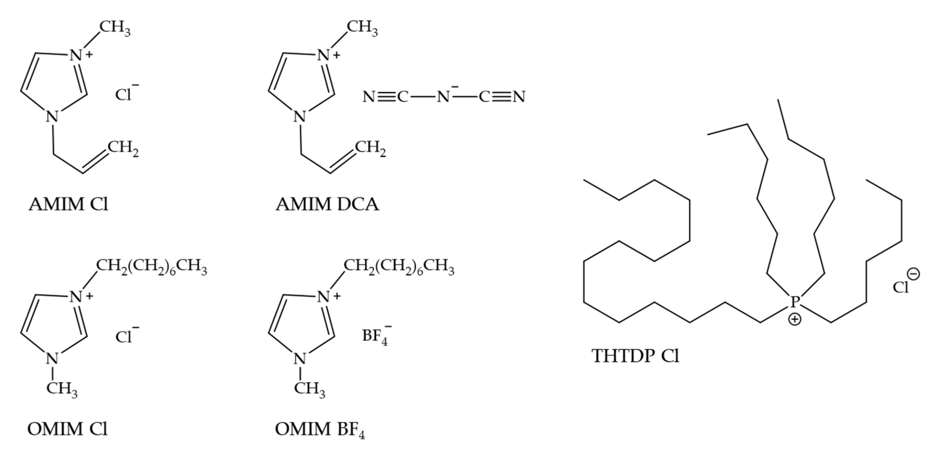
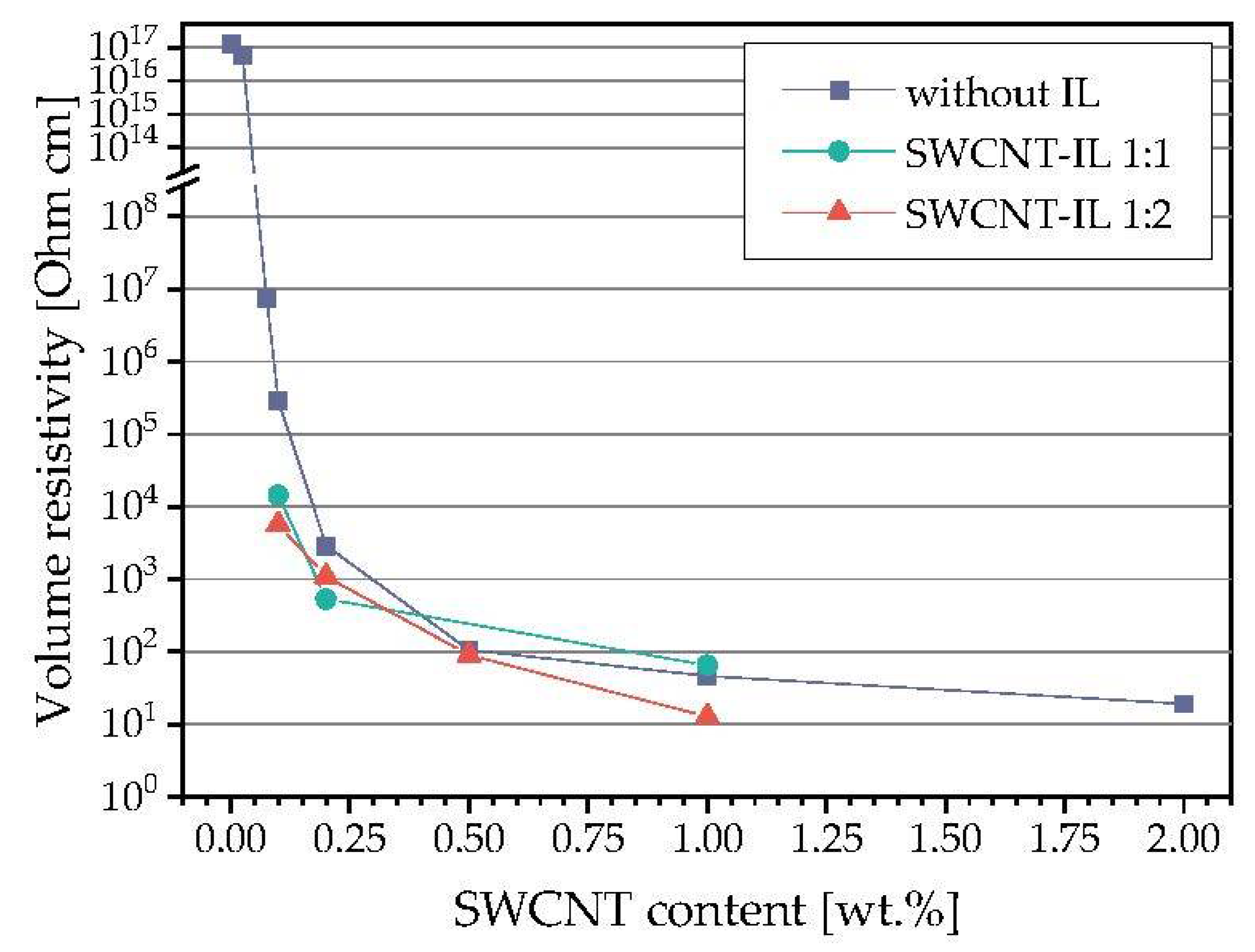
3.1.1. Electrical Percolation after Addition of Ils in Different Ratios

Firstly, composites filled with different concentrations of SWCNTs were characterized to determine the electrical percolation threshold of the PP/SWCNT system. Afterwards, the influence of the IL addition at two different CNT:IL ratios was investigated to study its effect on the electrical properties of the composites (Figure 2). The electrical percolation threshold for PP/SWCNT composites without the addition of IL was found between 0.05 wt.% and 0.075 wt.% and is slightly lower compared to another PP grades filled with the same SWCNT grade [53]. The addition of IL leads to a decrease in the resistivity values, with little difference in the resistivity values of the two selected SWCNT-IL ratios. Such decrease was found before for PP/SWCNT [7,24,63] and polyamide 12/MWCNT composites (PA12) [26]. Based on these results a SWCNT:IL ratio of 1:2 was chosen for further investigations.

3.1.2. Electrical Resistivity after Electron Beam Irradiation

In order to characterize the influence of EB irradiation on the electrical resistivity for selected samples, PP, PP blends with the IL AMIM-Cl, PP/SWCNT composites, and PP composites with SWCNTs and IL were treated using EB. As seen in Table 1, the electron beam irradiation had no significant influence on the electrical properties of PP and PP composites without IL. All composite samples had nearly the same resistivity value independent of the irradiation process. For the sample with 0.1 wt.% SWCNT, a slight increase in resistivity was observed after the EB treatment. The addition of this IL to PP does not show an effect; all samples are in the insulating range. For other (miscible) polymer-IL systems a decrease in the resistivity after the addition of the same amounts of IL was observed [50]. When looking at the effect of EB irradiation on the electrical resistivity of PP and PP/IL blends, only the sample with 1 wt.% AMIM Cl showed a slight decrease of one decade, whereas that with 2 wt.% AMIM Cl showed a relatively high decrease from 1017 to 5 × 10¹¹ Ohm cm. As for the PP/SWCNT composites, no influence of the EB treatment was seen after IL addition to the composites.

3.2. Morphological Characterisation

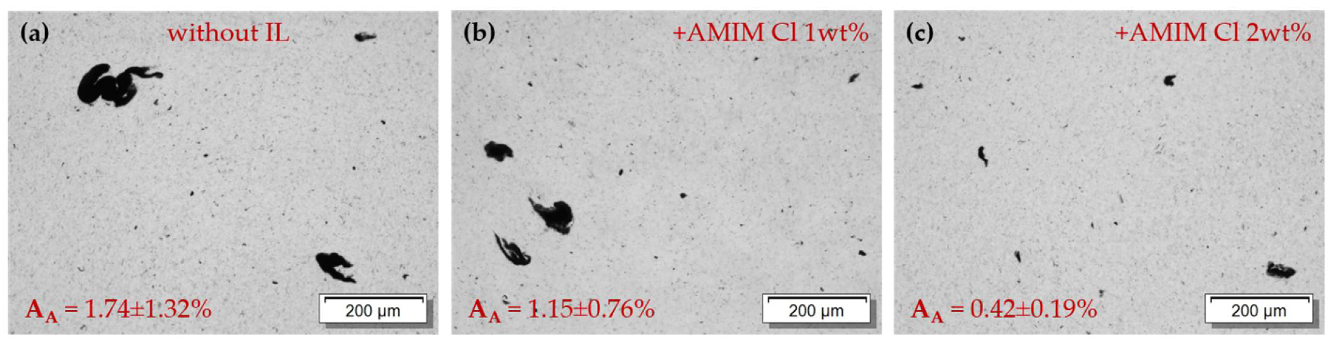
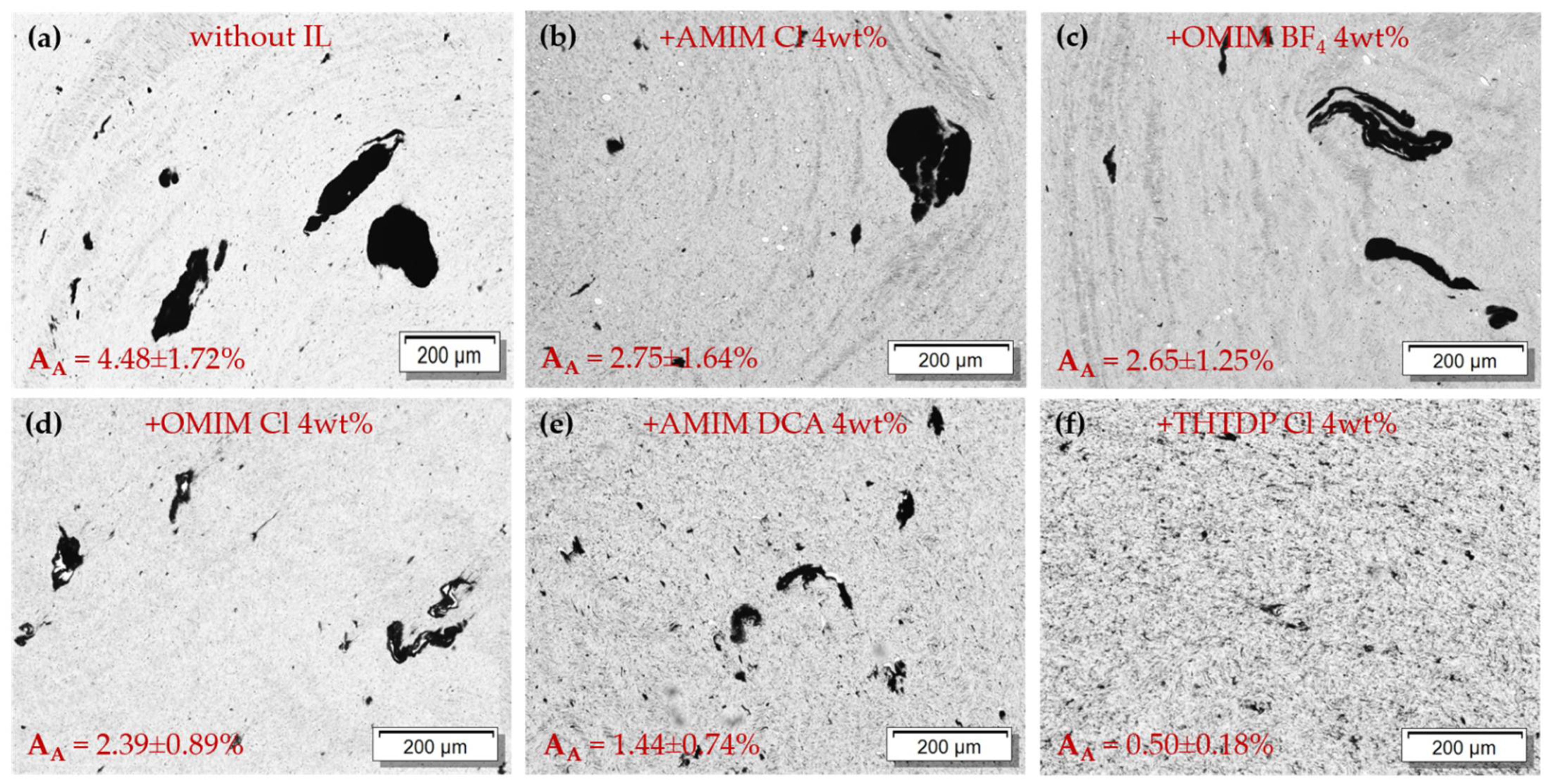
3.2.1. Light Microscopy

The state of macrodispersion of the SWCNTs (1 wt.%) in the PP matrix was investigated using light microscopy on thin sections. The PP composite with 1 wt.% SWCNT without IL had a remaining agglomerate area ratio of approx. 1.7% (Figure 3a). The typical stretched appearance of strands of Tuball™ SWCNT could be observed in melt-mixed composites, whereby big, curvy and meandered or muddled-like structures appeared. The addition of 1 wt.% IL AMIM Cl led to a better dispersion of the SWCNTs in the matrix (Figure 3b). At the higher SWCNT:IL ratio of 1:2 a further decrease in the agglomerate area ratio could be observed with a significantly better dispersion (Figure 3c). For the SWCNT:IL ratio of 1:1 a remaining agglomerate area ratio of approx. 1.2% and for a ratio of 1:2 only 0.4% could be quantified.
This trend was already shown for PVDF/CNT/IL composites [27] in which 1-butyl-3-methylimidazoliumhexafluorophosphat (BMIM-PF6) was used as ionic liquid. Compared to other PP/CNT/IL composites, where no influence of the addition of IL on the state of macrodispersion was found [24], a significant improvement in the state of dispersion was achieved in our study. Considering these results, the selection of the SWCNT: IL ratio of 1:2 was confirmed to be suitable, which was also seen in the reduced electrical resistivity when using this ratio.
Light microscopy images, including the agglomerate area ratios for PP/2 wt.% SWCNT composites with all five used ILs, are summarized in Figure 4. The PP/2 wt.% SWCNT composite without IL has a remaining area ratio of approx. 4.5%. As expected, a strong decrease in these remaining agglomerate areas could be observed, depending on the type of the used IL. The CNT macrodispersion with the lowest agglomerate area ratio of 0.5% was achieved when the IL of the type THTDP Cl was used. The other ILs reached AA values between 2.4–2.8% (AMIM Cl, OMIM BF4, OMIM Cl) and of 1.4% (AMIM DCA).
The dispersion of electron-irradiated composites was not investigated, as it is not expected that the CNT dispersion is affected during the EB treatment of the solid composites.

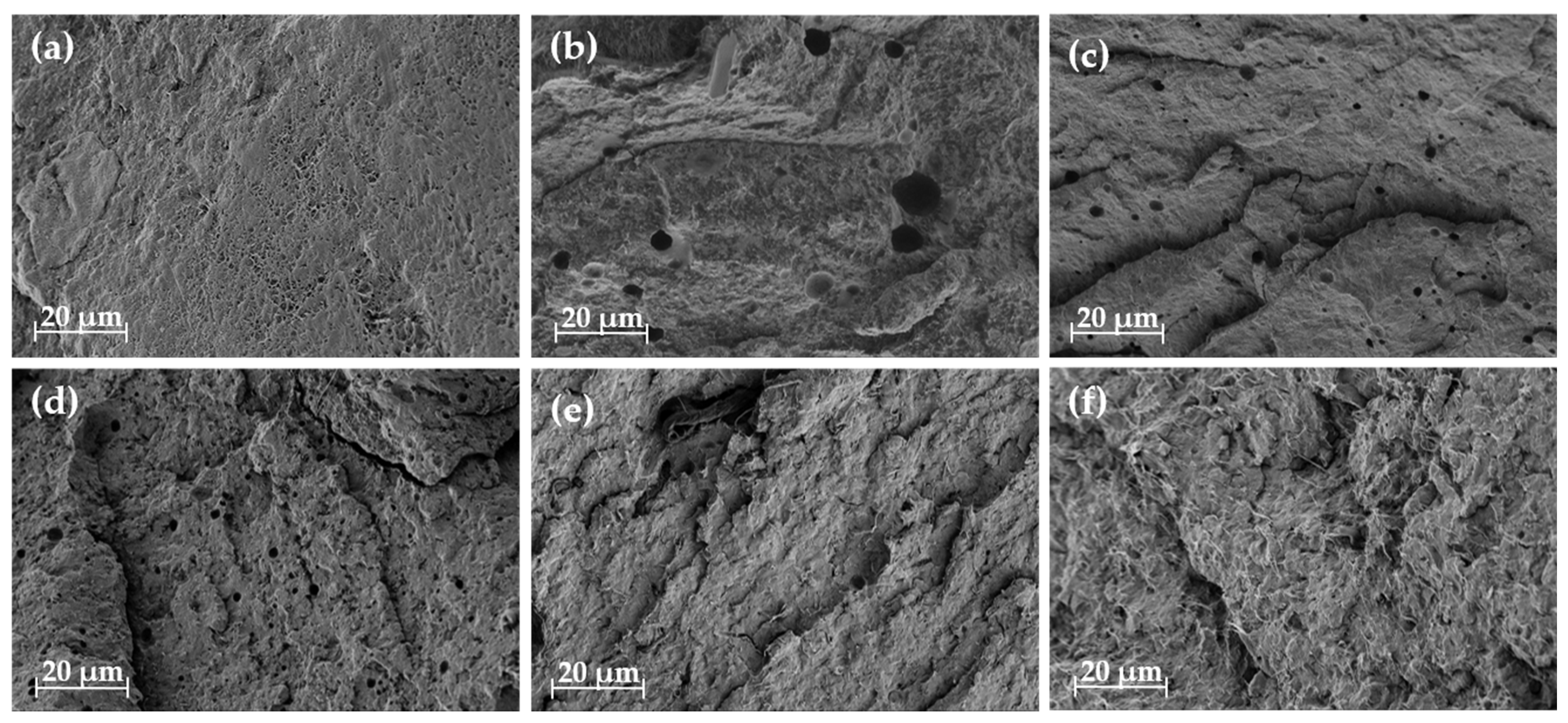
3.2.2. Scanning Electron Microscopy

The aim of the SEM study was to assess whether the ILs and the used PP are miscible. Therefore, the PP composite strands with 2 wt.% SWCNT were cryo-fractured, and the fractured surfaces were used for the SEM investigations (Figure 5). The PP/2 wt.% SWCNT composite without IL showed a homogenous SWCNT distribution in the PP matrix. The addition of the different ILs led to a change in the appearance of the composite morphology. In Figure 5b–d SEM images PP/2 wt.% SWCNT composites with 4 wt.% AMIM Cl (b), OMIM BF4 (c) and OMIM Cl (d) are presented. For these three samples many holes and spherical voids in the matrix are visible which can be assigned to IL domains. For the PP composite containing the IL AMIM DCA (Figure 5e) only a few holes are visible. It can be concluded that these ILs and the PP matrix are immiscible, which was also shown in former investigation with the IL OMIM BF4 [7]. As the ILs have a more polar character compared to PP, this result was expected. It is assumed that a part of IL which wet the SWCNTs first during the composite preparation procedure is localized at the nanotube surface, whereas another part separates as small droplets visible in the SEM images.
In contrast, in the SEM image of PP composite with the IL THTDP Cl (Figure 5f) no holes or other irregularities are visible. The SWCNTs are more clearly exposed on the surface of the fracture showing a homogeneous distribution of connected SWCNT bundles in the PP matrix. The image indicates that THTDP Cl and PP are miscible. This result is consistent with the fact that the IL THTDP Cl is less polar than the other ILs because it is soluble in toluene and hexane. In contrast, the four imidazolium-based ILs are soluble in polar solvents, such as water, acetonitrile and isopropanol. Therefore, the polarity of THTDP Cl is more similar to the non-polar PP matrix.

3.3. Thermal Characterization

Differential scanning calorimetry (DSC) was used to assess the thermal properties of PP, blends with the ILs, and composites without and with IL before and after irradiation. Table 2 shows the characteristic values of the thermal properties when using the IL AMIM Cl.
When comparing non-irradiated composites with pure processed PP, the glass transition temperatures (Tg) are nearly comparable. However, after the EB treatment a slight decrease of about 2 K is observed for the composites containing 1 wt.% SWCNT and 2 wt.% AMIM Cl and the blend of PP with this IL, whereas the Tg of pure PP is not influenced.
Comparing the melting temperatures (Tm) of non-irradiated samples, no influence of the addition of the IL could be observed, which is consistent with former studies [24]. Furthermore, adding SWCNTs leads to an increase in Tm of approx. 3 K, regardless of whether the composite contains IL or not, which is the same trend reported in [64]. The EB treatment results in a slight decrease in the melting temperatures by 1 K.
A major change is observable by comparing the onset (Tc,o) and maximum (Tc,m) crystallization temperatures after the addition of SWCNTs. This addition leads to 16 K and 15 K higher values, respectively, in composites without and with IL. The higher the SWCNT loading, the more pronounced this increase. For example, an increase of only 10 K (Tc,o) and 9 K (Tc,m) was described for a SWCNT addition to PP of 0.1 wt.% [24]. In [65], incorporation of 2 wt.% SWCNT in PP leads to an increase in Tc,m from 115.6 °C to 129 °C.
Moreover, the addition of the IL to PP leads to a slight decrease of both values by approx. 1–2 K. The addition of 2 wt.% IL to PP/1 wt.% SWCNT composite leads to no change of crystallization temperatures. The EB treatment has no further influence on the crystallization temperatures.
The enthalpy values ∆Hm are influenced by the sample composition as well. The addition of AMIM Cl without SWCNTs leads to a decrease by 4–5 J/g. Moreover, the presence of SWCNTs in the composites without IL results in an increase in the enthalpy by approx. 3 J/g. These findings are in agreement with previous results reported by Krause et al. [24] again. PP/SWCNT composites with the IL show higher enthalpy values by approx. 5 J/g then composites without IL. The EB treatment of composites without SWCNTs leads to a slight increase in the enthalpy. However, irradiated composites containing SWCNTs clearly show a decrease in the enthalpy. Regarding the calculated crystallinities Xc, values between 53% and 57% were calculated for all samples. The blends with the IL AMIM Cl only have 1% lower crystallinity than the pure PP. For composites containing SWCNTs the enthalpy is increased. After the EB no further influence could be observed. Overall, there is no dominant effect of the EB in relation to the thermal properties of the PP, blends, and composites.

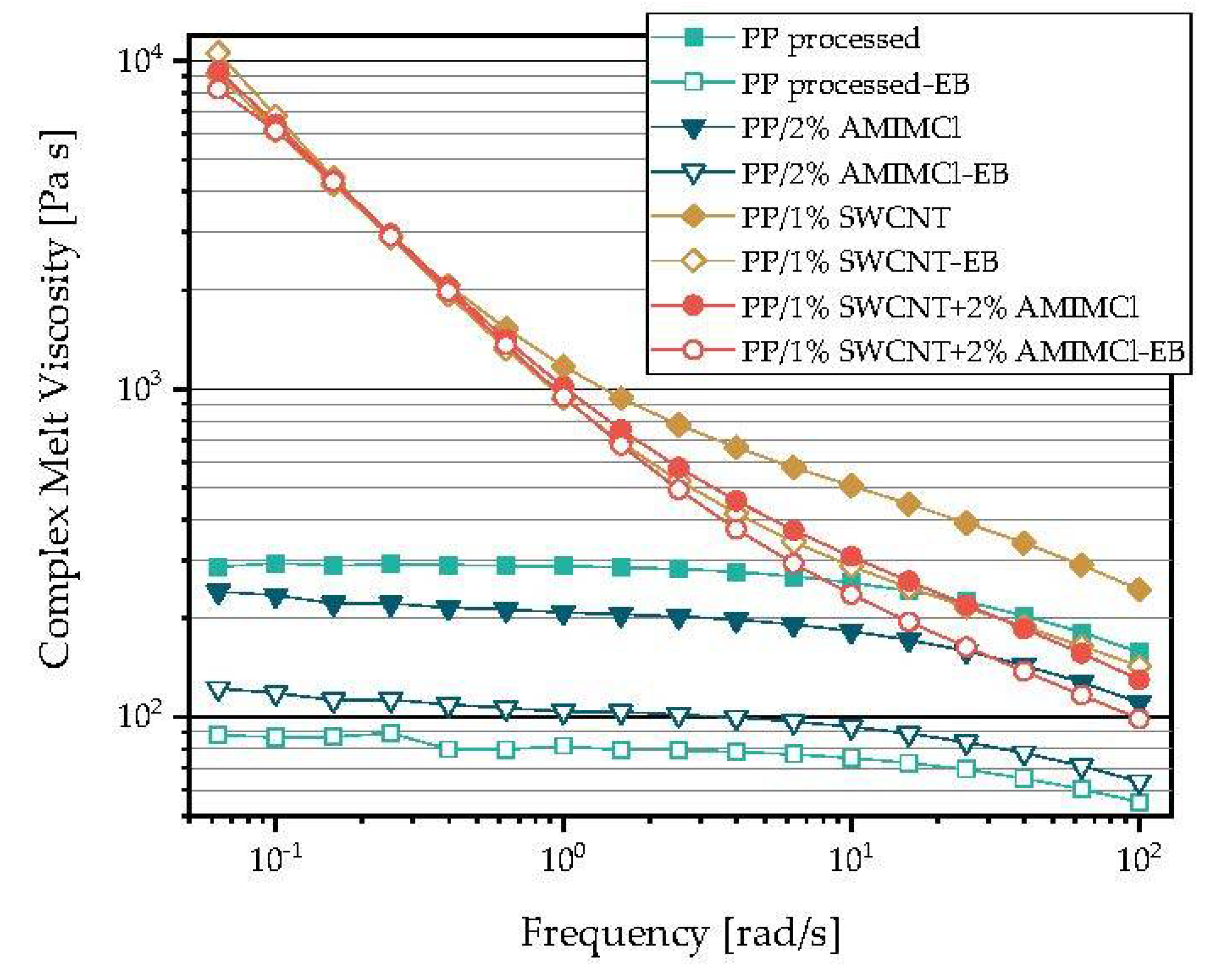
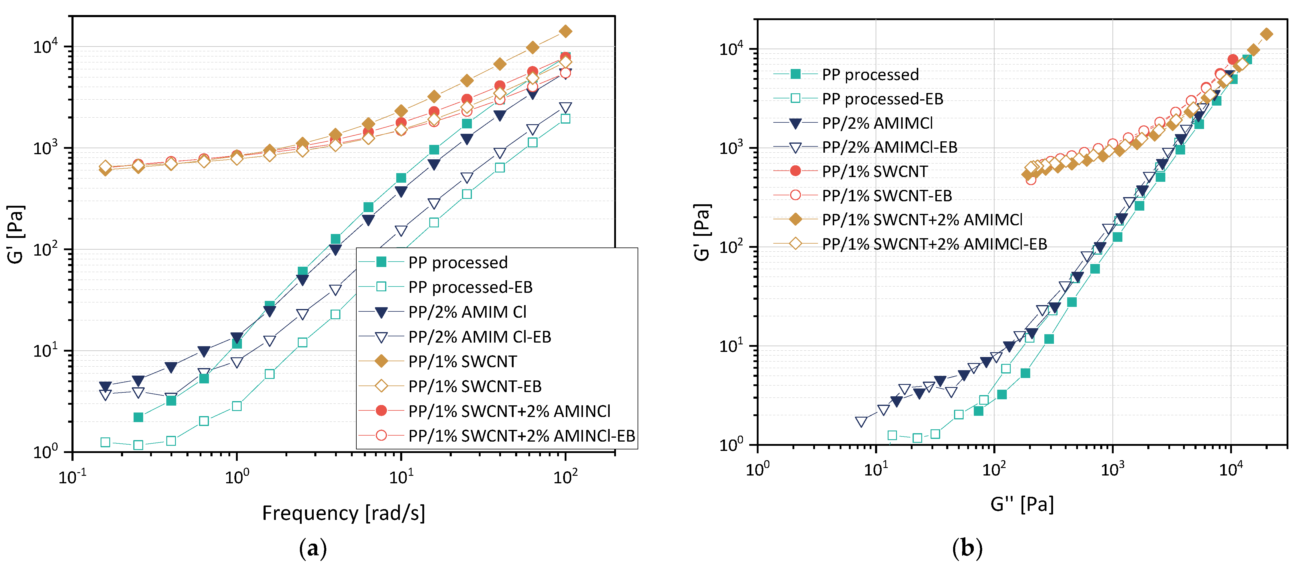
3.4. Melt Rheological Properties

In Figure 6 the complex melt viscosity in dependence on frequency is shown for PP composites with 1 wt.% SWCNT and/or 2 wt.% IL (used: AMIM Cl) before and after irradiation. It was found that the melt viscosity decreases for unfilled PP and the PP/IL blend after the EB treatment. The drop is lower for PP/IL than for PP, which may be due to the ability of the IL to form dimers under irradiation [49].
Significantly enhanced viscosities are found for the CNT-filled composites, especially at low frequencies indicating the percolated state of the SWCNTs. At high frequencies, the viscosity of PP/SWCNT composites with IL is lower than that of PP/SWCNT composites, showing the softening and lubrication effect of the added IL. After EB treatment, the viscosity decreases at high measurement frequencies, but is the same or even slightly higher at very low frequencies. The difference between the EB treated and non-treated samples is higher in the case of SWCNTs only and lower when IL is added. The decrease in viscosity at higher frequencies after the EB treatment could be caused by the molecular degradation process that typically occurs when PP is irradiated, whereas the slight increase at low frequencies may be attributed to chain branches that are expected also to be formed during EB treatment as shown before [41].
The illustration of the storage modulus G’ (Figure 7a) and loss modulus G′′ also shows a significant influence of the CNT addition ion the rheological properties. The reinforcing effect of the CNTs is clearly recognizable. In the G′ vs. G′′ plot (Figure 7b), the much higher elasticity of the samples containing SWCNTs can be seen which reflects the network effect of the nanotubes. At the same G′′ value, the G′ values are slightly higher in the EB treated samples, showing again a small effect of branching or crosslinking. However, the influence of the EB treatment and the IL addition are relatively small. PP shows after EB treatment higher G′ values (at the same G′′ values) whereas such effect is less pronounced after IL addition.

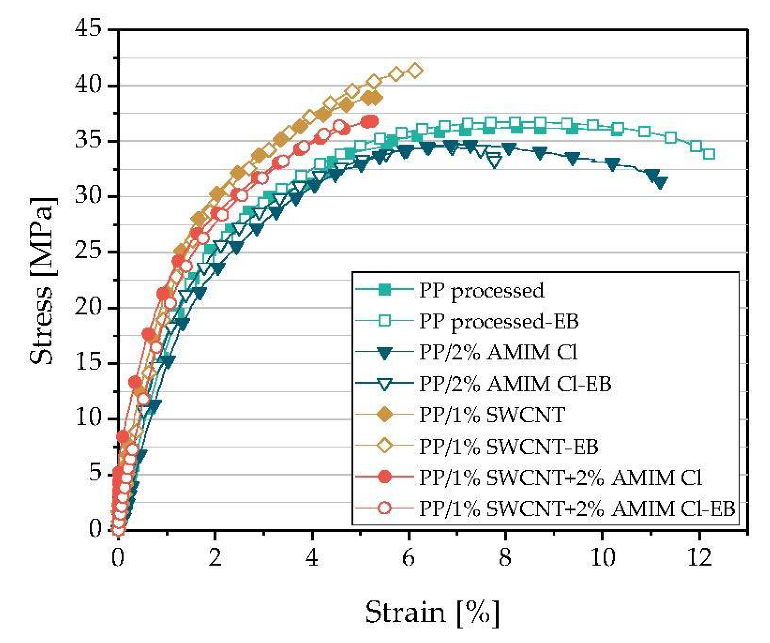
3.5. Mechanical Properties

For selected samples a stress–strain study was performed to examine the influence of IL addition and irradiation on mechanical properties (Figure 8, Table 3). As expected from the literature [66], for PP composites filled with SWCNT (with/without IL) the E modulus as well as the strain at break is higher and the elongation at break is lower compared to PP and PP/IL composites (Table 3). In addition, the CNT addition causes the sample to break before or at a maximum in the stress–strain curve. The IL addition to PP leads to slightly lower maximal stress, strain at maximum as well as strain at break and E modulus. The mechanical properties of composites containing both SWCNTs, and IL reflect the properties of both fillers, with the reinforcing effect of the SWCNTs predominating. Irradiation of the PP/SWCNT composites leads predominantly to lower elastic moduli compared to non-irradiated composites. In the composites containing SWCNTs, the EB treatment results in slightly higher strains at maximum values (σB = σM) and decreased values of elongation at maximum (εB = εM). When both SWCNT and IL are present, we cannot observe an unambiguous effect. After EB treatment, the E modulus, strain at maximum and elongation at maximum decreased for PP composites with 0.1 and 1 wt% SWCNT composites (0.2 and 2 wt.% AMIM Cl) and increase for the PP/0.5 wt.% + 1 wt.% AMIM Cl.
The achieved mechanical properties do not meet our expectation of improved interfacial adhesion between PP and imidazolium-based ionic liquid modified SWCNT due to electron beam induced radical formation on PP and IL. All characteristic values of PP/IL in stress–strain curve are reduced after irradiation indicating, more a softening effect than an interphase coupling. Furthermore, no clear coupling effect between IL treated SWCNTs with PP can be deduced after EB treatment. One reason for this only marginal observed change of mechanical properties of PP/IL could be the relatively low irradiation dose of 18 kGy, which was, however, chosen to limit the material degradation of the polypropylene (Figure 6). Thus, the goal of improving the mechanical properties by creating graft bonds between the allyl substituents of the IL and the PP matrix could not be achieved at the preparation conditions selected (IL and SWCNT content, IL type, irradiation dose).

3.6. Thermoelectric Properties

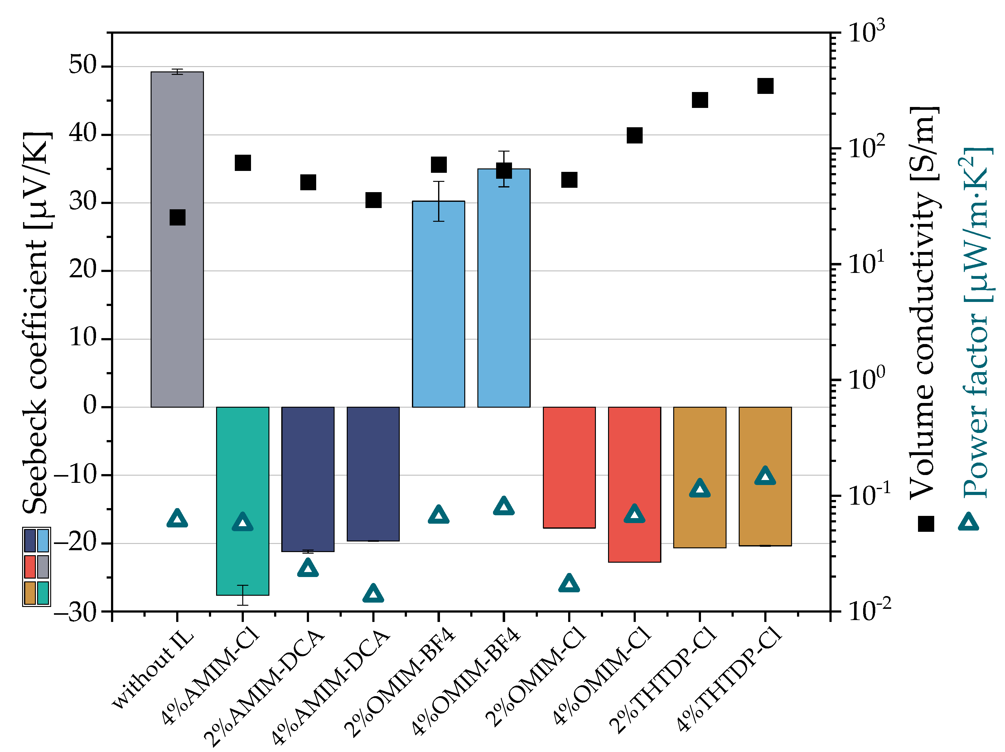
3.6.1. Different Kinds of Ionic Liquids as Additive in PP/2 wt.% SWCNT Composites

Five different types of ionic liquids were investigated as additives in PP/2 wt.% SWCNT composites with respect to their influence on the thermoelectric properties and switching from p-to n-type behavior. For this, composites with the SWCNT:IL ratios of 1:1 and 1:2 were melt-mixed. The obtained Seebeck coefficients as well as the electrical volume conductivities and power factors are shown in Figure 9. The PP/2 wt.% SWCNT composite without IL has a Seebeck coefficient of +49.3 µV/K, which implies a p-type character for this material. After adding the different ILs to the PP/SWCNT composite, a change in the thermoelectric performance could be observed. The Seebeck coefficients of the composites with four of the five ILs show clearly negative values, which indicates the n-type character for these samples. This is the case for the ILs AMIM Cl, AMIM DCA, OMIM Cl and THTDP Cl. The values are listed in Table 4. The most negative Seebeck coefficient was found with −27.6 µV/K for PP/2 wt.% SWCNT + 4 wt.% AMIM Cl, here the SWVNT:IL ratio of 1:1 was not prepared. Only the composite with the IL OMIM BF4 shows a positive Seebeck coefficient of around 30 to 35 µV/K, which is significantly lower than that of PP/SWCNTs. Compared to the values discussed by Luo et al. [7], who used a different PP matrix (Moplen 400R), three different SWCNT types (2 wt.%) and the same IL OMIM BF4 (2 wt.%), the observed trend was different, but the composites also had positive S-values. Here, the addition of IL led to an increase in the Seebeck coefficients from 23.2 to 39.6 µV/K (SWCNT type A), from 43.2 to 63.4 µV/K (SWCNT type B), and from 35.6 to 36.4 µV/K (SWCNT type mA) [7].
When using the higher IL amount, the Seebeck coefficient increases for samples mixed with OMIM BF4 (30.2 up to 35.0 µV/K) and AMIM DCA −21.2 to −19.7 µV/K). In contrast, the composite with OMIM Cl in the SWCNT:IL ratio of 1:2 results in a lower Seebeck value than at the 1:1 ratio (−17.8 up to −22.8 µV/K), indicating that the n-type behavior was even improved. Composites mixed with THTDP Cl are nearly unaffected by these two IL amounts (−20.7 and −20.4 µV/K).
Comparing the volume conductivities (Table 4) after the addition of the IL—no matter which kind—a strong increase in the values by two or three decades from 3 S/m up to 34,600 S/m was observed. Composites containing THTDP Cl have the highest and composites containing AMIM DCA the lowest volume conductivity. As the power factor PF depends on both, Seebeck coefficient and electrical volume conductivity, the addition of the different ILs show different effects. The PF value of the PP/2 wt.% SWCNT sample without IL is 0.082 µW/m·K2. After adding several ILs the power factor decreases for composites containing AMIM Cl, AMIM DCA, OMIM BF4 and OMIM Cl due to the lower values of the absolute Seebeck coefficient. For AMIM DCA the PF is even lower at higher IL loading, but for the OMIM-based IL it is higher at lower IL content. However, the composites mixed with THTDP Cl have for both SWCNT:IL ratios higher PF values (0.11 and 0.14 µW/mK2) than all other composites. The reason for that is the very high conductivity of these composites. Additionally, the change of the PF correlates with the change in the values for the figure of merit ZT, as the thermal conductivity was set as a constant value. For all PP/SWCNT/IL composites—except the one containing THTDP Cl—the ZT is lower compared to samples without IL. ZT varies in the range between 10−4 and 10−5. The lowest ZT for composites containing ILs could be observed for 2 wt.% AMIM DCA and OMIM Cl, and the best one at 4 wt.% OMIMBF4 and at both THTDP Cl ratios.

3.6.2. Influence of Pressing Time during Compression Molding on the Thermoelectric Properties (PP/1 wt.% SWCNT)

In Figure 10 the influence of different pressing times on the thermoelectric properties is shown. The pressing time is the period of time during which the composite is kept under pressure at the compression molding temperature of 210 °C. During this period, a rearrangement of the SWCNTs to secondary agglomerates is expected to take place, which strengthens the existing conductive filler network [67,68]. Thus, a longer pressing time can lead to a higher electrical conductivity.
The PP/1 wt.% SWCNT composites which were compression molded for two minutes represents the comparison for the composites with higher pressing time and shows a Seebeck coefficient of 46.6 µV/K. As seen in Figure 9, a longer pressing time leads to a continuous and significant decrease in the values of the Seebeck coefficient. After a pressing time of 30 min the Seebeck value reduced to 30.1 µV/K. On the other hand, the electrical volume conductivity increases with pressing times. Such an effect has already been described in the literature as a general tendency [68]. Despite the decreasing Seebeck coefficient values, due to the increasing volume conductivity of composites, the power factor also increased with pressing time. After two minutes pressing time, the electrical conductivity is 0.29 S/m and the PF 6.25 × 10⁻⁴ µW/m·K2, whereas after 30 min these values are 2.72 S/m and 4.26 × 10⁻³ µW/m·K2, respectively. The effect that causes an increase in the volume conductivity is accompanied by a decrease in the Seebeck coefficients is a general effect and has been described in literature, named as trade-off in thermoelectrics [1,69]. Similar to the power factor, the values of the figure of merit increase with higher pressing times by approx. one decade. The values for the characteristic thermoelectric parameter of all samples are summarized in Table 5.

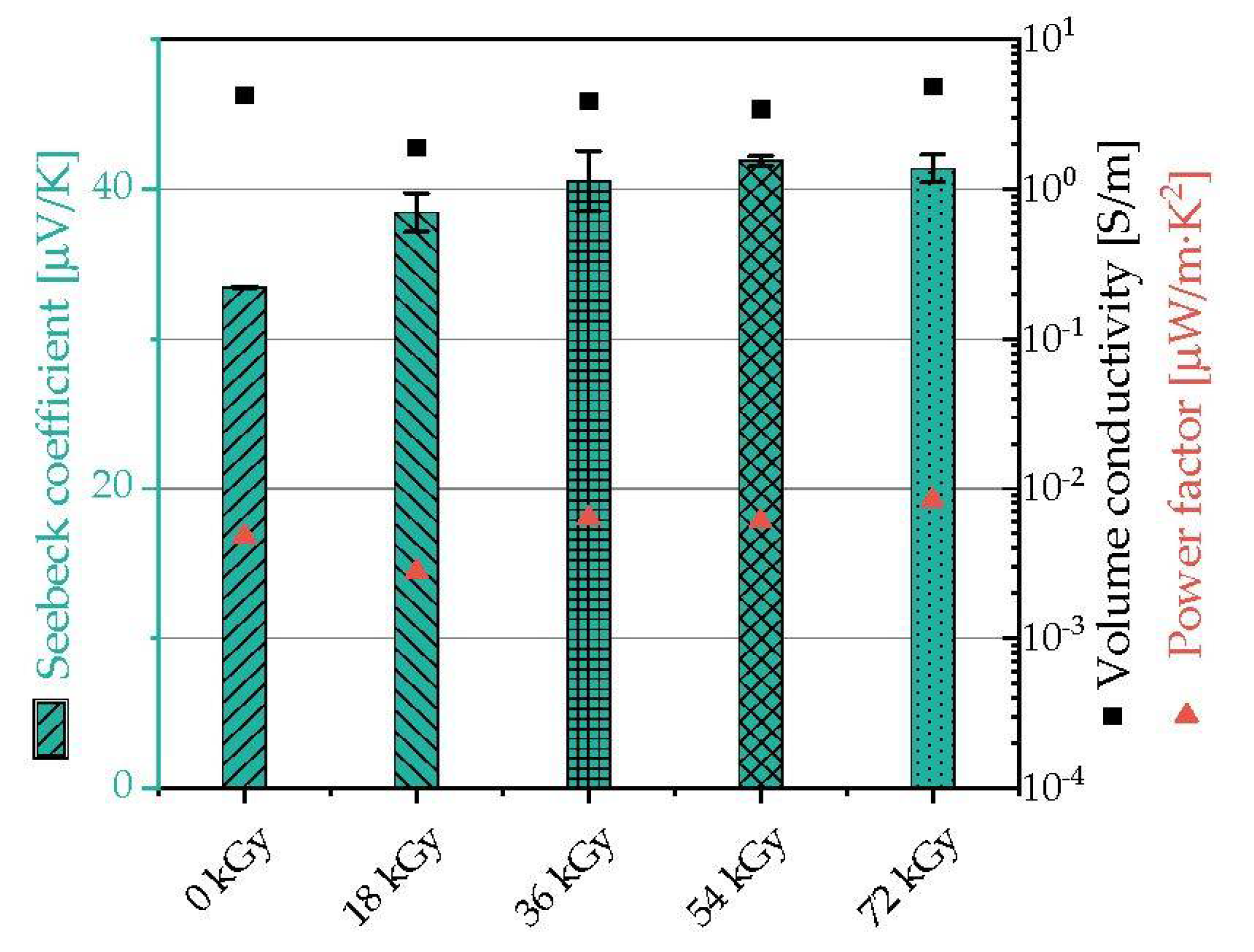
3.6.3. Influence of Electron Beam Irradiation Dose on the Thermoelectric Properties (PP/1 wt.% SWCNT)

Figure 11 shows the Seebeck coefficient as well as the volume conductivity and power factor depending on the irradiation dose for PP/1 wt.% SWCNT composites (Table 6). In this set, a masterbatch containing 5 wt.% SWCNT was diluted to 1 wt. composites. It is clearly visible that the irradiation itself leads to a significant increase in the Seebeck value. The starting composite has a Seebeck coefficient of 33.5 µV/K, and after the electron treatment with 18 kGy a value of 38.5 µV/K could be measured. Furthermore, the EB radiation with higher irradiation doses up to 72 kGy leads to a further slight increase in the Seebeck coefficient value, whereby values of approx. 41 µV/K are achieved.
It is assumed that this increase in the Seebeck coefficient is due to the changed polypropylene structure after the EB treatment. The irradiation introduces double bonds into the polypropylene [41,43], which increases the proportion of pi-electron bonds, which have a higher energy level than single bonds, in the polymer. This may have an electron-withdrawing effect on the CNTs, so that the number of positive charge carriers (holes) on the CNT increases. The p-type character of the conductive network would thus be strengthened, while de-localized electrons are enriched in the PP matrix. In the same way, radicals trapped in the crystalline phase of the PP after irradiation could act.
In addition to no significant influence of the irradiation dose on the electrical conductivity, power factor and figure of merit could be observed. Since the irradiation took place in the solid state, a change in the electrical conductivity was not expected.
The different processing routes of direct compounding and masterbatch dilution was compared for the composite PP/1 wt.% SWCNT. For this comparison, Figure 10 shows values which were obtained using the standard direct compounding, whereas the values in Figure 11 were measured on samples which were diluted from a 5 wt.% masterbatch. The volume conductivity of 4.3 S/m when using the masterbatch dilution is slightly higher than that of 0.3 S/m when using direct compounding. Interestingly, the Seebeck coefficient of the composite prepared by direct compounding, 33.5 µV/K, is significantly lower than that obtained using direct compounding, 46.6 µV/K. Here again, the well-known trade-off in thermoelectrics between the Seebeck coefficient and conductivity is seen which is difficult to overcome [1,69,70]. In a comprehensive study investigating different matrix polymers with CNT contents between 0.2 and 7 wt.%, it was found that a maximum Seebeck was in most cases reached between 0.5 and 1 wt.% loading, while the conductivity typically increased with increasing CNT content [14].

3.6.4. Influence of Electron Beam Irradiation on the Thermoelectric Properties (PP/1 wt.% SWCNT with and without IL)

Finally, the influence of EB radiation on the TE properties of composites containing IL was studied. Table 7 shows the Seebeck coefficients, volume conductivity, power factor and figure of Merit for PP/1 wt.% SWCNT composites with 2 wt.% AMIM Cl before and after the EB treatment. As described before, the addition of AMIM Cl leads to a composite with n-type character with the highest absolute Seebeck coefficient among all samples and therefore was selected. The EB treatment using 18 kGy resulted in a decrease in the absolute S-value at constant electrical conductivity resulting in a lower PF value.
To explain this result, one has to consider what the EB treatment causes in the IL part that covers the SWCNTs. Shkrob et al. [49] described that imidazolium-based ILs undergo various reactions during electron irradiation, such as deprotonation, cleavage of n-allyl groups, and formation of dimers from two imidazolyl radicals. These reaction products can change the n-type character of the IL doped SWCNTs because this reduces the number of double bonds and free electrode pairs resulting in a less n-type character. The conversion of the imidazole cation by irradiation reduces the electron affinity of the IL, which is important for the n-type character. Thus, the thermoelectric properties of the composite are expected to be more p-type.

4. Discussion

The results show that the addition of IL can change the properties of PP/SWCNT composites in different ways. On the one hand, the electrical resistivity is significantly lowered after IL addition. On the other hand, the addition of IL can also lead to a better distribution of the SWCNTs in the polymer matrix, which could be shown using light microscopy. This becomes particularly clear when using THTDP Cl, for which miscibility with the PP can be concluded from the SEM investigation. All other ILs used were not miscible with the non-polar PP due to their clearly more polar character.
In addition, all ILs were able to significantly change the thermoelectric properties of the PP/2 wt.% SWCNT composites. While the composites without IL show a p-type behavior, the addition of AMIM Cl, AMIM DCA, OMIM Cl and THTDP Cl changes the behavior to n-type and Seebeck coefficients between −17.8 µV/K and −27.6 µV/K were reached. In contrast, the addition of OMIM BF4 preserved the p-type character of the material, with the Seebeck coefficient decreasing from 49.3 µV/K to 30.2 µV/K (2 wt.% IL) or 35.0 µV/K (4 wt.% IL) due to the addition of IL. The anion of IL seems to play an important role, because the same cation (OMIM) in combination with the chloride anion leads to n-type composites. The BF4 anion contains the element boron, a p-type atom, which could be the reason why a switching to n-type does not take place. The dicyanamide, which contains nitrogen and carbon, and the chloride anion are rather n-type elements.
It is remarkable that whether the IL is miscible with PP or not, the TE properties are significantly affected. It is obviously sufficient that the IL can wet the SWCNTs during the manufacturing process.
Using the example of AMIM-Cl, it could be shown that the thermal behavior of the composites is not influenced by the addition of IL, which is in accordance with the literature [24]. Furthermore, the complex melt viscosity of the composites decreases moderately with the IL addition.
On the sample of PP/1 wt.% SWCNT it was demonstrated that an EB treatment with increasing doses leads to slightly higher Seebeck coefficients. Since the irradiation took place in the solid state, no change in the electrical conductivity was expected or found. It is assumed that the electrons introduced into the composite by the irradiation, leading to the formation of radicals, decrease the energy level in valence band followed by an improved thermoelectric p-type behavior [71,72]. Noori et al. [73] described that stable radical molecules (pyridine, 4-picoline, methyl group) adsorbed on the graphene nanoconstrictions can lead to an increase in the Seebeck coefficient due to transmission resonances near the Fermi energy.
The irradiation of PP/1 wt.% SWCNT composite containing 2 wt% IL leads to a less pronounced n-type behavior as seen in the change of the Seebeck coefficient from −16.3 µV/K to −10.1 µV/K. Here, both the introduction of electron beam-induced radicals into the composite and the structural changes of the imidazole-based IL itself play a role. Both lead to a more pronounced thermoelectric p-type behavior.
At the low dose of 18 kGy used, only a very low influence of the irradiation on the rheological and mechanical properties of the composites could be observed. There are slightly higher complex melt viscosities at low measuring frequencies in rheological tests and higher stress and elongation at break values in tensile tests if the PP/1 wt% SWCNT composite is EB treated. However, in composites containing IL such effect is not seen anymore. The tests, however, confirmed the well-known reinforcing effect of CNTs in polymers very clearly as seen by increased melt rheological parameters and enhanced tensile modulus and stress values. Increasing the irradiation dose may be a way to enhance the EB effects; however, due to the degradation of PP during the irradiation, such a high irradiation dose is only useful to a limited extent.

Author Contributions

Conceptualization, P.P., B.K. and M.T.M.; methodology, O.V., B.K. and M.T.M.; validation, O.V.; investigation, O.V. and M.T.M.; data curation, O.V.; writing—original draft preparation, O.V. and B.K.; writing—review and editing, P.P., M.T.M. and S.W.; visualization, B.K. and O.V.; supervision, S.W.; project administration, B.K. All authors have read and agreed to the published version of the manuscript.

Funding

This research received no external funding.

Data Availability Statement

The data presented in this study are available on request from the corresponding author.

Acknowledgments

The authors thank the collaborators of the IPF research technology department for their support, Ulrike Jentzsch-Hutschenreuther for the thermoelectric measurements and Manuela Heber (both IPF) for sample preparation and SEM imaging. In addition, the authors thank Kerstin Arnold for the DSC measurements, Anna Ivanova for the rheological study, and Holger Scheibner for the mechanical measurements (all IPF).

Conflicts of Interest

The authors declare no conflict of interest.

References

  1. Rowe, D.M. CRC Handbook of Thermoelectrics; CRC Press: Boca Raton, FL, USA, 1995. [Google Scholar]
  2. Gayner, C.; Kar, K.K. Recent advances in thermoelectric materials. Prog. Mater. Sci. 2016, 83, 330–382. [Google Scholar] [CrossRef]
  3. Antar, Z.; Feller, J.F.; Noël, H.; Glouannec, P.; Elleuch, K. Thermoelectric behaviour of melt processed carbon nanotube/graphite/poly(lactic acid) conductive biopolymer nanocomposites (CPC). Mater. Lett. 2012, 67, 210–214. [Google Scholar] [CrossRef]
  4. Shim, M.; Javey, A.; Shi Kam, N.W.; Dai, H. Polymer Functionalization for Air-Stable n-Type Carbon Nanotube Field-Effect Transistors. J. Am. Chem. Soc. 2001, 123, 11512–11513. [Google Scholar] [CrossRef] [PubMed]
  5. Sun, Y.-C.; Terakita, D.; Tseng, A.C.; Naguib, H.E. Study on the thermoelectric properties of PVDF/MWCNT and PVDF/GNP composite foam. Smart Mater. Struct. 2015, 24, 085034. [Google Scholar] [CrossRef] [Green Version]
  6. Luo, J.; Cerretti, G.; Krause, B.; Zhang, L.; Otto, T.; Jenschke, W.; Ullrich, M.; Tremel, W.; Voit, B.; Pötschke, P. Polypropylene-based melt mixed composites with singlewalled carbon nanotubes for thermoelectric applications: Switching from p-type to n-type by the addition of polyethylene glycol. Polymer 2017, 108, 513–520. [Google Scholar] [CrossRef]
  7. Luo, J.; Krause, B.; Pötschke, P. Polymer—Carbon nanotube composites for thermoelectric applications. AIP Conf. Proc. 2017, 1914, 030001. [Google Scholar] [CrossRef] [Green Version]
  8. Pötschke, P.; Krause, B.; Luo, J. Melt mixed composites of polypropylene with single walled carbon nanotubes for thermoelectric applications: Switching from p- to n-type behavior by additive addition. AIP Conf. Proc. 2019, 2055, 090004. [Google Scholar] [CrossRef]
  9. Luo, J.; Krause, B.; Pötschke, P. Melt-mixed thermoplastic composites containing carbon nanotubes for thermoelectric applications. AIMS Mater. Sci. 2016, 3, 1107–1116. [Google Scholar] [CrossRef]
  10. Piao, M.; Alam, M.R.; Kim, G.; Dettlaff-Weglikowska, U.; Roth, S. Effect of chemical treatment on the thermoelectric properties of single walled carbon nanotube networks. Phys. Status Solidi (b) 2012, 249, 2353–2356. [Google Scholar] [CrossRef]
  11. Dörling, B.; Sandoval, S.; Kankla, P.; Fuertes, A.; Tobias, G.; Campoy-Quiles, M. Exploring different doping mechanisms in thermoelectric polymer/carbon nanotube composites. Synth. Met. 2017, 225, 70–75. [Google Scholar] [CrossRef] [Green Version]
  12. Yeontack Ryu, D.F.; Yu, C. High electrical conductivity and n-type thermopower from double-/single-wall carbon nanotubes by manipulating charge interactions between nanotubes and organic/inorganic nanomaterials. Carbon 2011, 49, 4745–4751. [Google Scholar] [CrossRef]
  13. Brownlie, L.; Shapter, J. Advances in carbon nanotube n-type doping: Methods, analysis and applications. Carbon 2018, 126, 257–270. [Google Scholar] [CrossRef] [Green Version]
  14. Krause, B.; Barbier, C.; Levente, J.; Klaus, M.; Pötschke, P. Screening of different carbon nanotubes in melt-mixed polymer composites with different polymer matrices for their thermoelectric properties. J. Compos. Sci. 2019, 3, 106. [Google Scholar] [CrossRef] [Green Version]
  15. Paleo, A.J.; Vieira, E.M.F.; Wan, K.; Bondarchuk, O.; Cerqueira, M.F.; Goncalves, L.M.; Bilotti, E.; Alpuim, P.; Rocha, A.M. Negative thermoelectric power of melt mixed vapor grown carbon nanofiber polypropylene composites. Carbon 2019, 150, 408–416. [Google Scholar] [CrossRef]
  16. Paleo, A.J.; Krause, B.; Cerqueira, M.F.; Melle-Franco, M.; Pötschke, P.; Rocha, A.M. Thermoelectric properties of polypropylene carbon nanofiber melt-mixed composites: Exploring the role of polymer on their Seebeck coefficient. Polym. J. 2021, 53, 1145–1152. [Google Scholar] [CrossRef]
  17. Waldmann, T.; Huang, H.; Hoster, H.; Höfft, O.; Endres, F.; Behm, R. Imaging an Ionic Liquid Adlayer by Scanning Tunneling Microscopy at the Solid|Vacuum Interface. Chemphyschem 2011, 12, 2565–2567. [Google Scholar] [CrossRef]
  18. Hapiot, P.; Lagrost, C. Electrochemical Reactivity in Room-Temperature Ionic Liquids. Chem. Rev. 2008, 108, 2238–2264. [Google Scholar] [CrossRef]
  19. Wheatley, P.S.; Allan, P.K.; Teat, S.J.; Ashbrook, S.E.; Morris, R.E. Task specific ionic liquids for the ionothermal synthesis of siliceous zeolites. Chem. Sci. 2010, 1, 483–487. [Google Scholar] [CrossRef]
  20. Han, Y.; Qiao, D.; Zhang, L.; Feng, D. Study of tribological performance and mechanism of phosphonate ionic liquids for steel/aluminum contact. Tribol. Int. 2015, 84, 71–80. [Google Scholar] [CrossRef]
  21. Torimoto, T.; Tsuda, T.; Okazaki, K.-I.; Kuwabata, S. New Frontiers in Materials Science Opened by Ionic Liquids. Adv. Mater. 2010, 22, 1196–1221. [Google Scholar] [CrossRef]
  22. Walden, P. Ueber die Molekulargrösse und elektrische Leitfähigkeit einiger geschmolzener Salze (Molecular weights and elec-trical conductivity of several fused salts). Bull. l’Acad. Impériale Sci. St.-Pétersbourg 1914, 8, 405–422. [Google Scholar]
  23. Socher, R. PA12-MWCNT-Nanokomposite: Wege zur Effektiven MWCNT-Dispergierung und zu Niedrigen Elektrischen Perkolationsschwellen. Ph.D Thesis, Technische Universität Dresden, München, Germany, 2013. [Google Scholar]
  24. Krause, B.; Predtechenskiy, M.; Ilin, E.; Pötschke, P. PP/SWCNT composites modified with ionic liquid. AIP Conf. Proc. 2017, 1914, 030008. [Google Scholar] [CrossRef] [Green Version]
  25. Zhao, L.; Li, Y.; Cao, X.; You, J.; Dong, W. Multifunctional role of an ionic liquid in melt-blended poly(methyl methacrylate)/multi-walled carbon nanotube nanocomposites. Nanotechnology 2012, 23, 255702. [Google Scholar] [CrossRef] [PubMed]
  26. Socher, R.; Krause, B.; Pötschke, P. Effect of additives on MWCNT dispersion and electrical percolation in polyamide 12 composites. AIP Conf. Proc. 2017, 1914, 030016. [Google Scholar] [CrossRef] [Green Version]
  27. Ke, K.; Pötschke, P.; Gao, S.; Voit, B. An Ionic Liquid as Interface Linker for Tuning Piezoresistive Sensitivity and Toughness in Poly(vinylidene fluoride)/Carbon Nanotube Composites. ACS Appl. Mater. Interfaces 2017, 9, 5437–5446. [Google Scholar] [CrossRef]
  28. Heger, A.; Dorschner, H.; Dunsch, L.; Ihme, B.; Lunkwitz, K. Technologie der Strahlenchemie von Polymeren; Lang, H., Ed.; Akademie: Berlin, Germany, 1991; Volume 42, p. 613. [Google Scholar]
  29. Pospiech, D.; Korwitz, A.; Komber, H.; Jehnichen, D.; Arnhold, K.; Brünig, H.; Scheibner, H.; Müller, M.T.; Voit, B. Polyesters with bio-based ferulic acid units: Crosslinking paves the way to property consolidation. Polym. Chem. 2021, 12, 5139–5148. [Google Scholar] [CrossRef]
  30. Müller, M.T.; Zschech, C.; Gohs, U. Electron beam generated polymer-backbone-hydroperoxides trigger the crosslinking of glass fibre polypropylene interphase. AIP Conf. Proc. 2019, 2065, 030026. [Google Scholar] [CrossRef]
  31. Khatiwada, S.P.; Gohs, U.; Lach, R.; Heinrich, G.; Adhikari, R. A New Way of Toughening of Thermoset by Dual-Cured Thermoplastic/Thermosetting Blend. Materials 2019, 12, 548. [Google Scholar] [CrossRef] [Green Version]
  32. Huang, Y.; Müller, M.T.; Boldt, R.; Zschech, C.; Gohs, U.; Wießner, S. Improved Rheology, Crystallization, and Mechanical Performance of PLA/mPCL Blends Prepared by Electron-Induced Reactive Processing. ACS Sustain. Chem. Eng. 2021, 9, 3478–3489. [Google Scholar] [CrossRef]
  33. Huang, Y.; Gohs, U.; Müller, M.T.; Zschech, C.; Wiessner, S. Evaluation of electron beam-induced crosslinking of poly(ε-caprolactone)—Effect of elevated temperatures. J. Appl. Polym. Sci. 2019, 136, 47866. [Google Scholar] [CrossRef]
  34. Gohs, U.; Mueller, M.T.; Zschech, C.; Zhandarov, S. Enhanced Interfacial Shear Strength and Critical Energy Release Rate in Single Glass Fiber-Crosslinked Polypropylene Model Microcomposites. Materials 2018, 11, 2552. [Google Scholar] [CrossRef] [PubMed] [Green Version]
  35. Müller, M.T.; Zschech, C.; Gedan-Smolka, M.; Pech, M.; Streicher, R.; Gohs, U. Surface modification and edge layer post curing of 3D sheet moulding compounds (SMC). Radiat. Phys. Chem. 2020, 173, 108872. [Google Scholar] [CrossRef]
  36. Zaharescu, T.; Setnescu, R.; Jipa, S.; Setnescu, T. Radiation processing of polyolefin blends. I. Crosslinking of EPDM–PP blends. J. Appl. Polym. Sci. 2000, 77, 982–987. [Google Scholar] [CrossRef]
  37. Rätzsch, M.; Arnold, M.; Borsig, E.; Bucka, H.; Reichelt, N. Radical reactions on polypropylene in the solid state. Prog. Polym. Sci. 2002, 27, 1195–1282. [Google Scholar] [CrossRef]
  38. Lazár, M.; Hrčková, L.U.; Borsig, E.; Marcinčin, A.; Reichelt, N.; Rätzsch, M. Course of degradation and build-up reactions in isotactic polypropylene during peroxide decomposition. J. Appl. Polym. Sci. 2000, 78, 886–893. [Google Scholar] [CrossRef]
  39. Lugão, A.B.; Hutzler, B.; Ojeda, T.; Tokumoto, S.; Siemens, R.; Makuuchi, K.; Villavicencio, A.L.C.H. Reaction mechanism and rheological properties of polypropylene irradiated under various atmospheres. Radiat. Phys. Chem. 2000, 57, 389–392. [Google Scholar] [CrossRef]
  40. Krause, B.; Voigt, D.; Lederer, A.; Auhl, D.; Münstedt, H. Determination of low amounts of long-chain branches in polypropylene using a combination of chromatographic and rheological methods. J. Chromatogr. A 2004, 1056, 217–222. [Google Scholar] [CrossRef]
  41. Auhl, D.; Stange, J.; Münstedt, H.; Krause, B.; Voigt, D.; Lederer, A.; Lappan, U.; Lunkwitz, K. Long-chain branched polypropylenes by electron beam irradiation and their rheological properties. Macromolecules 2004, 37, 9465–9472. [Google Scholar] [CrossRef]
  42. Krause, B.; Stephan, M.; Volkland, S.; Voigt, D.; Häussler, L.; Dorschner, H. Long-chain branching of polypropylene by electron-beam irradiation in the molten state. J. Appl. Polym. Sci. 2006, 99, 260–265. [Google Scholar] [CrossRef]
  43. Krause, B.; Häussler, L.; Voigt, D. Comparison of the molecular properties and morphology of polypropylenes irradiated under different atmospheres and after annealing. J. Appl. Polym. Sci. 2006, 100, 634–639. [Google Scholar] [CrossRef]
  44. Krause, B.; Voigt, D.; Haussler, L.; Auhl, D.; Munstedt, H. Characterization of electron beam irradiated polypropylene: Influence of irradiation temperature on molecular and rheological properties. J. Appl. Polym. Sci. 2006, 100, 2770–2780. [Google Scholar] [CrossRef]
  45. Zschech, C.; Miersch, F.; Gohs, U.; Heinrich, G. Elektroneninduzierte reaktive Aufbereitung von Polypropylen/Ethylen-Octen Copolymer Blends—Eine neue Methode zur Herstellung zähmodifizierten Polypropylens. Kunststofftechnik 2016, 12, 112–134. [Google Scholar] [CrossRef] [Green Version]
  46. Razavi Aghjeh, M.; Khonakdar, H.A.; Jafari, S.H.; Zschech, C.; Gohs, U.; Heinrich, G. Rheological, morphological and mechanical investigations on ethylene octene copolymer toughened polypropylene prepared by continuous electron induced reactive processing. RSC Adv. 2016, 6, 24651–24660. [Google Scholar] [CrossRef]
  47. Rola, K.P.; Zając, A.; Szpecht, A.; Kowal, D.; Cybińska, J.; Śmiglak, M.; Komorowska, K. Interaction of electron beam with ionic liquids and its application for micropatterning. Eur. Polym. J. 2021, 156, 110615. [Google Scholar] [CrossRef]
  48. Shkrob, I.A.; Marin, T.W.; Chemerisov, S.D.; Wishart, J.F. Radiation Induced Redox Reactions and Fragmentation of Constituent Ions in Ionic Liquids. 1. Anions. J. Phys. Chem. B 2011, 115, 3872–3888. [Google Scholar] [CrossRef]
  49. Shkrob, I.A.; Marin, T.W.; Chemerisov, S.D.; Hatcher, J.L.; Wishart, J.F. Radiation Induced Redox Reactions and Fragmentation of Constituent Ions in Ionic Liquids. 2. Imidazolium Cations. J. Phys. Chem. B 2011, 115, 3889–3902. [Google Scholar] [CrossRef]
  50. Xing, C.; Zhao, M.; Zhao, L.; You, J.; Cao, X.; Li, Y. Ionic liquid modified poly(vinylidene fluoride): Crystalline structures, miscibility, and physical properties. Polym. Chem. 2013, 4, 5726–5734. [Google Scholar] [CrossRef]
  51. Xing, C.; Wang, Y.; Zhang, C.; Li, L.; Li, Y.; Li, J. Immobilization of Ionic Liquids onto the Poly(vinylidene fluoride) by Electron Beam Irradiation. Ind. Eng. Chem. Res. 2015, 54, 9351–9359. [Google Scholar] [CrossRef]
  52. Xing, C.; Wang, Y.; Huang, X.; Li, Y.; Li, J. Poly(vinylidene fluoride) Nanocomposites with Simultaneous Organic Nanodomains and Inorganic Nanoparticles. Macromolecules 2016, 49, 1026–1035. [Google Scholar] [CrossRef]
  53. Krause, B.; Pötschke, P.; Ilin, E.; Predtechenskiy, M. Melt mixed SWCNT-polypropylene composites with very low electrical percolation. Polymer 2016, 98, 45–50. [Google Scholar] [CrossRef]
  54. Kunz, K.; Krause, B.; Kretzschmar, B.; Juhasz, L.; Kobsch, O.; Jenschke, W.; Ullrich, M.; Pötschke, P. Direction Dependent Electrical Conductivity of Polymer/Carbon Filler Composites. Polymers 2019, 11, 591. [Google Scholar] [CrossRef] [PubMed] [Green Version]
  55. Dorschner, H.; Jenschke, W.; Lunkwitz, K. Radiation field distributions of an industrial electron beam accelerator. Nucl. Instrum. Methods Phys. Res. Sect. B 2000, 161–163, 1154–1158. [Google Scholar] [CrossRef]
  56. Körber, H.; Lappan, U.; Geißler, U.; Lunkwitz, K.; Hanke, R. Physical and Chemical Modification Apparatus for Material Samples Comprises a Housing with a Radiation Beam Window, Sample Table on a Support and a Sample Pressure Applicator. Patent No. DE19930742, 15 February 2001. [Google Scholar]
  57. Jenschke, W.; Ullrich, M.; Krause, B.; Pötschke, P. Messanlage zur Untersuchung des Seebeck-Effektes in Polymermaterialien—Measuring apparatus for study of Seebeck-effect in polymer materials. Tech. Messen 2020, 87, 495–503. [Google Scholar] [CrossRef]
  58. Gnanaseelan, M.; Chen, Y.; Luo, J.; Krause, B.; Pionteck, J.; Pötschke, P.; Qi, H. Cellulose-carbon nanotube composite aerogels as novel thermoelectric materials. Compos. Sci. Technol. 2018, 163, 133–140. [Google Scholar] [CrossRef]
  59. Krause, B.; Barbier, C.; Kunz, K.; Pötschke, P. Comparative study of singlewalled, multiwalled, and branched carbon nanotubes melt mixed in different thermoplastic matrices. Polymer 2018, 159, 75–85. [Google Scholar] [CrossRef]
  60. Krause, B.; Rzeczkowski, P.; Pötschke, P. Thermal Conductivity and Electrical Resistivity of Melt-Mixed Polypropylene Composites Containing Mixtures of Carbon-Based Fillers. Polymers 2019, 11, 1073. [Google Scholar] [CrossRef] [Green Version]
  61. Krause, B.; Pötschke, P. Electrical and thermal conductivity of polypropylene filled with combinations of carbon fillers. AIP Conf. Proc. 2016, 1779, 040003. [Google Scholar]
  62. Wunderlich, B. Thermal Analysis; Academic Press: New York, NY, USA, 1990; p. 464. [Google Scholar]
  63. Pötschke, P.; Krause, B.; Luo, J. Melt-mixed thermoplastic polymer/carbon nanotube composites for thermoelectric applications. TechConnect Briefs 2018, 1, 196–199. [Google Scholar]
  64. Jam, J.E.; Ahangari, M. Study of the Mechanical, Thermal Properties and Morphology of Polypropylene Nanocomposites in the Presence of Compatibilizer. Polym.-Plast. Technol. Eng. 2012, 51, 1186–1192. [Google Scholar] [CrossRef]
  65. Biswas, S.; Muzata, T.S.; Krause, B.; Rzeczkowski, P.; Pötschke, P.; Bose, S. Does the Type of Polymer and Carbon Nanotube Structure Control the Electromagnetic Shielding in Melt-Mixed Polymer Nanocomposites? J. Compos. Sci. 2020, 4, 9. [Google Scholar] [CrossRef] [Green Version]
  66. Ganß, M.; Satapathy, B.K.; Thunga, M.; Weidisch, R.; Pötschke, P.; Jehnichen, D. Structural interpretations of deformation and fracture behavior of polypropylene/multi-walled carbon nanotube composites. Acta Mater. 2008, 56, 2247–2261. [Google Scholar] [CrossRef]
  67. Alig, I.; Pötschke, P.; Lellinger, D.; Skipa, T.; Pegel, S.; Kasaliwal, G.R.; Villmow, T. Establishment, morphology and properties of carbon nanotube networks in polymer melts. Polymer 2012, 53, 4–28. [Google Scholar] [CrossRef]
  68. Kasaliwal, G.; Göldel, A.; Pötschke, P. Influence of processing conditions in small-scale melt mixing and compression molding on the resistivity and morphology of polycarbonate–MWNT composites. J. Appl. Polym. Sci. 2009, 112, 3494–3509. [Google Scholar] [CrossRef]
  69. Mori, T.; Hara, T. Hybrid effect to possibly overcome the trade-off between Seebeck coefficient and electrical conductivity. Scr. Mater. 2016, 111, 44–48. [Google Scholar] [CrossRef]
  70. Kang, S.-W.; Kim, S.; Cho, C.; Choi, K. Experimental investigation of the dependence of the thermoelectric performance of carbon nanotubes/polymer nanocomposites on the synthesis protocol. Funct. Compos. Struct. 2020, 2, 035001. [Google Scholar] [CrossRef]
  71. Ahangari, M.G.; Fereidoon, A.; Jahanshahi, M.; Ganjic, M.D. Electronic and mechanical properties of single-walled carbon nanotubes interacting with epoxy: A DFT study. Physica E 2013, 48, 148–156. [Google Scholar] [CrossRef]
  72. Foa Torres, L.E.F.; Roche, S.; Charlier, J.-C. Introduction to Graphene-Based Nanomaterials: From Electronic Structure to Quantum Transport; Cambridge University Press: Cambridge, UK, 2014. [Google Scholar] [CrossRef]
  73. Noori, M.; Sadeghi, H.; Lambert, C.J. Stable-radicals increase the conductance and Seebeck coefficient of graphene nanoconstrictions. Nanoscale 2018, 10, 19220–19223. [Google Scholar] [CrossRef] [Green Version]
Figure 1. Chemical structures for the used ionic liquids (Ils).
Jcs 06 00025 g001
Figure 2. Volume resistivity in dependence on SWCNT content without and with IL (used IL: AMIM Cl).
Jcs 06 00025 g002
Figure 3. Light microscopy images and agglomerate area ratios of different composites: (a) PP/1 wt.% SWCNT, (b) PP/1 wt.% SWCNT + 1 wt.% AMIM Cl and (c) PP/1 wt.% SWCNT + 2 wt.% AMIM Cl.
Jcs 06 00025 g003
Figure 4. Light microscopy images and agglomerate area ratios of different composites: (a) PP/2 wt.% SWCNT, (b) PP/2 wt.% SWCNT + 4 wt.% AMIM Cl, (c) PP/2 wt.% SWCNT + 4 wt.% OMIM BF4, (d) PP/2 wt.% SWCNT + 4 wt.% OMIM Cl, (e) PP/2 wt.% SWCNT + 4 wt.% AMIM DCA and (f) PP/2 wt.% SWCNT + 4 wt.% THTDP Cl.
Jcs 06 00025 g004
Figure 5. SEM images of cryo-fractured surfaces for different composites: (a) PP/2 w t% SWCNT, (b) PP/2 wt.% SWCNT/4 wt.% AMIM Cl, (c) PP/2 wt.% SWCNT/4 wt.% OMIM BF4, (d) PP/2 wt.% SWCNT/4 wt.% OMIM Cl, (e) PP/2 wt.% SWCNT/4 wt.% AMIM DCA and (f) PP/2 wt.% SWCNT/4 wt.% THTDP Cl.
Jcs 06 00025 g005
Figure 6. Complex melt viscosity (at 210 °C) of unfilled PP, PP/IL, PP/SWCNT and PP/SWCNT/IL composites before (filled) and after (empty) electron beam irradiation (18 kGy).
Jcs 06 00025 g006
Figure 7. (a) Storage modulus G′ in dependence on frequency and (b) loss modulus G″ at 210 °C of unfilled PP, PP/IL, PP/SWCNT and PP/SWCNT/IL composites before (filled symbols) and after (open symbols) electron beam irradiation (18 kGy).
Jcs 06 00025 g007
Figure 8. Typical stress-strain curves of various composites without and with IL (AMIM Cl) before and after the irradiation (EB, 18 kGy).
Jcs 06 00025 g008
Figure 9. Seebeck coefficient, volume conductivity and power factor of PP/2 wt.% SWCNT composites with five different kinds of IL at 40 °C.
Jcs 06 00025 g009
Figure 10. Seebeck coefficient, volume conductivity and power factor of PP/1 wt.% SWCNT composites at 40 °C, compression molding at different pressing times.
Jcs 06 00025 g010
Figure 11. Seebeck coefficient, volume conductivity and power factor of PP/1 wt.% SWCNT composites (obtained by masterbatch dilution) irradiated at 40 °C with different doses.
Jcs 06 00025 g011
Table 1. Electrical resistivity values before and after electron beam irradiation of PP, PP/SWCNT, PP/IL and PP/SWCNT/IL composites; used IL: AMIM Cl, dose of 18 kGy.
SampleVolume Resistivity before Irradiation [Ohm cm]Volume Resistivity after Irradiation [Ohm cm]
PP-processed3.07 × 10171.11 × 1017
PP/0.1 wt.% SWCNT7.72 × 1046.48 × 105
PP/1 wt.% SWCNT4.49 × 1013.37 × 101
PP/0.2 wt.% AMIM Cl1.03 × 10171.32 × 1017
PP/1 wt.% AMIM Cl1.41 × 10173.23 × 1016
PP/2 wt.% AMIM Cl1.25 × 10175.09 × 1011
PP/0.1 wt.% SWCNT 0.2 wt.% AMIM Cl1.40 × 1041.29 × 104
PP/1 wt.% SWCNT+2 wt.% AMIM Cl1.12 × 1011.63 × 101
Table 2. Characteristic values of DSC measurements and calculated crystallinities for non-irradiated and irradiated (EB) PP, PP/IL, PP/CNT, and PP-CNT-IL composites; used IL: AMIM Cl, dose 18 kGy.
SampleTg [°C]Tm [°C]Tc,o [°C]Tc,m [°C]∆Hm [J/g]Xc [%]
PP-processed−7.0158.6121.9119.7112.254.2
PP-processed-EB−7.0156.9121.9119.8113.354.7
PP/2 wt.% AMIM Cl−7.0158.0120.5117.6108.453.4
PP/2 wt.% AMIM Cl-EB−9.4156.8120.1117.4109.053.7
PP/1 wt.% SWCNT−8.1161.6137.6134.2116.056.6
PP/1 wt.% SWCNT-EB−10.3160.8137.5134.1115.656.4
PP/1 wt.% SWCNT + 2 wt.% AMIM Cl−7.1161.4137.6134.2113.956.7
PP/1 wt.% SWCNT + 2 wt.% AMIM Cl-EB−8.0160.6137.4134.1109.454.5
Table 3. Mechanical properties for non-irradiated and irradiated (EB) PP, PP/IL, PP/CNT, and PP/CNT-IL composites; used IL: AMIM Cl, dose 18 kGy.
SampleEt [MPa]σM [MPa]εM [%]σB [MPa]εB [%]
PP-processed1823 ± 9936.7 ± 0.58.2 ± 0.235.6 ± 0.411.1 ± 1.7
PP-processed-EB1841 ± 12136.7 ± 0.38.3 ± 0.132.8 ± 1.112.5 ± 1.7
PP/0.2 wt.% AMIM Cl1718 ± 7635.4 ± 0.58.4 ± 0.333.3 ± 1.012.3 ± 2.4
PP/0.2 wt.% AMIM Cl-EB1711 ± 6736.0 ± 0.68.0 ± 0.632.6 ± 3.310.6 ± 2.4
PP/1 wt.% AMIM Cl1696 ± 8234.9 ± 0.47.5 ± 0.330.8 ± 0.712.1 ± 3.6
PP/1 wt.% AMIM Cl-EB1805 ± 9135.4 ± 0.47.6 ± 0.330.3 ± 0.611.4 ± 2.9
PP/2 wt.% AMIM Cl1726 ± 5733.0 ± 0.66.5 ± 0.830.6 ± 2.010.0 ± 3.8
PP/2 wt.% AMIM Cl-EB1727 ± 10734.7 ± 0.46.9 ± 0.533.2 ± 1.49.6 ± 2.9
PP/0.1 wt.% SWCNT1947 ± 6335.8 ± 0.79.5 ± 0.8MM
PP/0.1 wt.% SWCNT-EB2019 ± 5536.9 ± 0.68.6 ± 0.9MM
PP/0.5 wt.% SWCNT2186 ± 5938.4 ± 0.76.0 ± 0.9MM
PP/0.5 wt.% SWCNT-EB2033 ± 7637.1 ±1.65.4 ± 1.0MM
PP/1 wt.% SWCNT2276 ± 5439.0 ± 1.25.4 ± 0.7MM
PP/1 wt.% SWCNT-EB2218 ± 8241.1 ± 0.86.0 ± 0.6MM
PP/0.1 wt.% SWCNT + 0.2 wt.% AMIM Cl2050 ± 4237.3 ± 0.58.3 ± 0.6MM
PP/0.1 wt.% SWCNT + 0.2 wt.% AMIM Cl-EB1980 ±9236.8 ± 0.58.3 ± 1.3MM
PP/0.5 wt.% SWCNT + 1 wt.% AMIM Cl2059 ± 6837.2 ± 0.56.7 ± 1.0MM
PP/0.5 wt.% SWCNT + 1 wt.% AMIM Cl-EB2254 ± 6538.2 ± 0.86.0 ± 0.7MM
PP/1 wt.% SWCNT + 2 wt.% AMIM Cl2155 ± 12637.7 ± 1.15.4 ± 0.6MM
PP/1 wt.% SWCNT + 2 wt.% AMIM Cl-EB2087 ± 11635.4 ± 2.54.4 ± 0.9MM
Et = Elastic modulus, σM = tensile strength at maximum, εm = elongation at maximum, σB = tensile strength at break, εB = elongation at break.
Table 4. Thermoelectric parameters at 40 °C of the PP/2 wt.% SWCNT composites mixed with different ILs shown in Figure 9.
SampleSeebeck Coefficient
S [µV/K]
Volume Conductivity [S/m]Power Factor
PF [µW/m·K2]
Figure of Merit ZT [-]
PP/2 wt.% SWCNT+49.33.39 × 1010.0821.17 × 10−4
PP/2 wt.% SWCNT + 4 wt.% AMIM Cl−27.67.50 × 1010.0578.15 × 10−5
PP/2 wt.% SWCNT + 2 wt.% AMIM DCA−21.25.10 × 1010.0233.27 × 10−5
PP/2 wt.% SWCNT + 4 wt.% AMIM DCA−19.73.57 × 1010.0141.97 × 10−5
PP/2 wt.% SWCNT + 2 wt.% OMIM BF4+30.27.27 × 1010.0669.43 × 10−5
PP/2 wt.% SWCNT + 4 wt.% OMIM BF4+35.06.43 × 1010.0791.12 × 10−4
PP/2 wt.% SWCNT + 2 wt.% OMIM Cl−17.85.37 × 1010.0172.41 × 10−5
PP/2 wt.% SWCNT + 4 wt.% OMIM Cl−22.81.40 × 1020.0679.58 × 10−5
PP/2 wt.% SWCNT + 2 wt.% THTDP Cl−20.72.62 × 1020.1121.59 × 10−4
PP/2 wt.% SWCNT + 4 wt.% THTDP Cl−20.43.46 × 1020.1432.04 × 10−4
Table 5. Thermoelectric parameters of the composites at 40 °C compression molded using different pressing times shown in Figure 10.
Sample PP/1 wt.% SWCNT
Pressing Time
Seebeck Coefficient
S [µV/K]
Volume Conductivity [S/m]Power Factor
PF [µW/mK2]
Figure of Merit ZT [-]
2 min46.60.296.25 × 10−46.99 × 10⁻⁷
5 min39.92.724.33 × 10−34.84 × 10⁻⁶
10 min40.02.463.94 × 10−34.41 × 10⁻⁶
20 min35.43.874.83 × 10−35.41 × 10⁻⁶
30 min30.14.724.26 × 10−34.77 × 10⁻⁶
Table 6. Thermoelectric parameters of PP/1 wt.% SWCNT composites irradiated at 40 °C with different doses shown in Figure 11.
Sample PP/1 wt.% SWCNT
Irradiation Dose
Seebeck Coefficient
S [µV/K]
Volume Conductivity [S/m]Power Factor PF
[µW/mK2]
Figure of Merit ZT [-]
0 kGy33.54.284.78 × 10−35.35 × 10⁻⁶
18 kGy38.51.892.80 × 10−33.13 × 10⁻⁶
36 kGy40.63.876.35 × 10−37.11 × 10⁻⁶
54 kGy41.93.456.05 × 10−36.76 × 10⁻⁶
72 kGy41.44.888.35 × 10−39.34 × 10⁻⁶
Table 7. Thermoelectric parameters at 40 °C of PP/1 wt.% SWCNT composites with 2 wt.% AMIM Cl before and after electron beam irradiation (18 kGy).
SampleSeebeck Coefficient
S [µV/K]
Volume Conductivity
[S/m]
Power Factor
PF [µW/mK2]
Figure of Merit ZT [-]
PP/1 wt.% SWCNT + 2 wt.% AMIM Cl−16.32.38 × 10−10.0066.84 × 10−6
PP/1 wt.% SWCNT + 2 wt.% AMIM Cl-EB−10.12.21 × 10−10.0022.35 × 10−6
Publisher’s Note: MDPI stays neutral with regard to jurisdictional claims in published maps and institutional affiliations.

