

Application of Composite Materials for Energy Generation Devices


1
Department of Manufacturing Processes and Production Engineering, Rzeszow University of Technology, al. Powst. Warszawy 8, 35-959 Rzeszów, Poland
2
College of Electrical and Mechanical Engineering, Addis Ababa Science and Technology University, Addis Ababa P.O. Box 16417, Ethiopia
3
Department of Aerospace Engineering, Ethiopian Space Science and Technology Institute, Addis Ababa, P.O. Box 33679, Ethiopia
4
Department of Mechanical Engineering, University of Gondar, Gondar P.O. Box 196, Ethiopia
5
Department of Mechanical and Structural Engineering, University of Stavanger, N-4036 Stavanger, Norway
*
Author to whom correspondence should be addressed.
J. Compos. Sci. 2023, 7(2), 55; https://0-doi-org.brum.beds.ac.uk/10.3390/jcs7020055
Submission received: 29 December 2022
/
Revised: 16 January 2023
/
Accepted: 1 February 2023
/
Published: 3 February 2023
(This article belongs to the Special Issue Opportunities for Composites in the Future Energy Systems)
Abstract
:Globally, electricity demand rises by 1.8% per year; according to the American Energy Information Administration, global energy demand will increase by 47% over the next 30 years, driven by demographic and economic growth. Global demand for electricity is growing faster than renewable energy sources. Electricity production from renewable sources (i.e., biomass energy, geothermal energy, hydro energy, solar energy, tidal energy, wind energy) is on its way to strong growth around the world over the next dozen years. With the increasing demand for energy, new technologies and materials are being developed to replace exhaustible traditional construction materials. This article aims to provide a comprehensive overview of the research into the application of composite materials in mainstream power generation. The main energy generation technologies, i.e., photovoltaic panels, wind turbines, fuel cells, and biogas generators, were analysed and discussed. The review presented in this article also covers the latest achievements and prospects for the use of composite materials in energy generation devices.
Keywords:
composites; biomass power; fibre metal laminates; fuel cells; FML; green energy; nanocomposites; solar PVs1. Introduction
Currently, renewable energy is gaining an increasingly leading position (Figure 1) in the face of the increased depletion of fossil fuels and the desire to protect the natural environment. The development of energy generation devices requires the use of appropriate materials that are highly durable on the one hand and environmentally friendly on the other. The use of metals produced by metallurgical methods is limited due to their high weight and relatively low fatigue strength [1]. Interest in composite materials results from the fact that they represent mechanical and strength parameters similar to metallic materials and, at the same time, their low weight, which extends their use in structures where the weight of the structure is of primary importance. Composites containing fibre fillers that prevent crack propagation are more resistant to cracking and fatigue loads compared to metallic materials [2,3]. The basic indicator of the fibres used in the production of composites is the specific strength as the ratio of the tensile strength to the specific weight of the fibre material [4]. The specific strength of aramid and carbon fibres is six times higher than titanium and ten times higher than steel. The largest energy generation devices (i.e., wind turbines) are exposed to corrosion, in particular in a salty marine environment. Under these conditions, only composite materials can be used to build rotor blades to provide the appropriate durability of the structure. Composites also make it possible to obtain materials with properties that cannot be obtained by metallurgical methods of metallic materials [5]. However, increasing environmental protection requirements, as well as the subsequent obligation to dispose of the products, makes it necessary to select composites taking into account their recycling [6,7]. Currently, wind turbine elements are commonly made of carbon fibre-reinforced plastics, which are difficult to recycle. Many turbines manufactured in the 20th century require repairs and renovations. So, it is an opportunity to use more sustainable materials, which have developed significantly in recent years with the methods of their design and processing. The world is moving into a new era for wind energy, according to The European Composites Industry Association (ECIA), the weight of used wind turbines is 2.5 million tons, and in the next few years, 12,000 turbines will have to be replaced or modernized [8]. There is currently a need for the substitution of difficult to degrade, or completely non-biodegradable polymers, for renewable ones of natural origin, which are fully biodegradable [9,10].
In general, composite materials used in energy generation devices fulfil two functions. The first group of composite materials is used to provide the structure with adequate strength (i.e., rotor blades of wind turbines). The second group consists of conducting polymers, which are attractive organic materials for future high-throughput energy storage applications due to their flexibility, lightweight, controllable resistance over a wide range, cost-effectiveness and high conductivity (>103 S·cm−1) [11]. Conductive polymers can be coated on another material and incorporated into composites due to their good material affinity. Furthermore, the physicochemical properties (i.e., miscibility, cross-linking, affinity and chemical stability) of electroactive polymers can also be controlled by modifying their chemical structures [12].
Modern construction materials in the form of composites are being tested in many different applications related to energy production, solar cells, supercapacitors, vehicles, fuel cells, wind turbines, hydropower and biogas generators. Typical sources of electricity are shown schematically in Figure 2. Composites containing organic polymers, in addition to conductive properties, also exhibit desirable properties such as electronic, magnetic, wetting, optical, mechanical and microwave absorption properties. According to El-Ghoul et al. [13], conducting polymers (CP) generally are classified into the following three principal groups: conducting polymer composites [14,15], intrinsically conducting polymers (ICPs), [16,17] and ionic conducting polymers [18]. The general application of the nanomaterial-based polymers and their composites in many various applications related to energy production and storage are shown in Figure 3.
A composite is a man-made material made of two or more components (phases) with different properties. The properties of the multiphase material produced in this way are the result of the properties of the components with different physical and mechanical properties. One of the components is the matrix that binds the composite together, and the other is the construction material responsible for giving the composite the appropriate strength, which is the result of the properties of the component phases, the volume fraction of the phases, the distribution of the dispersed phase in the matrix and the geometrical features of the dispersed phase [19,20]. The appropriate combination of component materials and their orientation makes it possible to obtain a material with properties impossible to obtain by classical methods of producing homogeneous materials.
Depending on the intended use, composites are divided into structural and composites with specific physical or chemical properties. The division of composites according to the type of matrix distinguishes composites with a metallic and non-metallic matrix (polymer, ceramic and semiconductor). Classification of the composites is shown in Figure 4.
Figure 1.
Worldwide energy consumption, prepared on the basis of [21].
Figure 1.
Worldwide energy consumption, prepared on the basis of [21].

Figure 2.
Sources of the electricity: (a) biogas, (b) wind (a—monopile; b—gravity-based; c—jacket; d—tripod; e—tripole; f—spar type; g and h tension-legged; i semi-submersible), (c) photovoltaics, (d) hydrology and (e) geothermal. Prepared with permissions from [22] (Copyright © 2020 Hydrogen Energy Publications LLC. Published by Elsevier Ltd.), Ref. [23] (Copyright © 2021 Elsevier Ltd.), Ref. [24] (Copyright © 2022 Elsevier Ltd.) and [25] (Copyright © 2013 Elsevier Inc.).

Metallic or non-metallic matrixes are reinforced with dispersion, molecular or fibrous reinforcing phases (aramid, basalt, glass, carbon fibres, etc.). Metal matrix composites (MMCs) are a group of heterogeneous materials consisting of at least two different interconnected components that occupy specific geometric forms in the composite material and characterize it with their volume fraction [26,27]. Their matrix consists of metals (e.g.: tungsten, cobalt, nickel, iron), which in the process of their formation, occur in the powdered form [28,29].
MMCs are classified according to the method of their production as follows [26]:
- Ex situ—their reinforcing phase is prepared in a separate process and then introduced into the matrix material;
- In situ—their reinforcement is created in the liquid matrix of the composite during the metallurgical process as a result of chemical reactions taking place between its components.
Figure 3.
Applications of conducting polymers.

Composites with a non-metallic matrix are divided into a polymer (polymer matrix composites—PMCs) and ceramic (ceramic matrix composites—CMCs) [30]. PMCs usually form thermoplastic and thermosetting synthetic polymers formed from the combination of simple molecules (so-called monomers) with low molecular weight. They are formed as a result of a reaction called polymerization. CMCs are a group of materials with a brittle ceramic matrix with micro- and nanometric dimensions [31]. Ceramic matrix composites are materials with a brittle ceramic matrix (Al2O3, AlN, SiC, sialon), in which grains of the also brittle, second ceramic phase are distributed [32]. In the vast majority, they are produced by typical ceramic technology. In these composites, it is possible to obtain an increase in strength and/or fracture toughness compared to single-phase polycrystals [33].
Figure 4.
Classification of the composite materials.

Dispersion-reinforced composites are made of a metal matrix reinforced with fine ceramic or metallic particles with a diameter of 0.01 ÷ 0.1 μm and a volume fraction in the composite of about 15%. The volume fraction of the reinforcing phase in this type of composite does not exceed 90%. Fibre-reinforced composites, depending on the fibre length, include short fibres (up to approx. 0.3 mm), long fibres (0.3 ÷ 20 mm) and continuous fibres (the fibre length is much greater than fibre diameter d) [33]. The fibres may be unoriented or oriented when the fibres are directional [34]. Polymer composites can be reinforced with glass fibres (glass fibre-reinforced polymers—GFRPs), carbon fibres (carbon fibre-reinforced polymers—CFRPs) or aramid fibres (aramid fibre-reinforced plastics—AFRPs).
Hybrid composites (fibre metal laminates—FMLs) consist of different construction materials. Initially, FMLs were developed for applications in the aviation industry; in this way, the weight of structural elements was reduced without reducing the strength and fatigue properties of the components [35,36]. FMLs consist of adhesively joined thin layers of metal sheets with a polymer composite reinforced with aramid, glass and carbon fibres [37]. There are two main groups of fibre metal laminates. The first of them are composites based on aluminium alloy sheets. The second group includes composites in which other metals were used, such as the following: magnesium [38,39], titanium [40,41] or steel [42,43].
Aluminium-based hybrid composites are commonly known as glass-reinforced aluminium laminates (GLARE), consisting of 2–6 layers of aluminium alloy sheets (GLARE 1—7475-T761, GLARE 2–6—2024-T3) with a thickness of 0.2 up to 0.5 mm. Layers of fibres bonded with an epoxy resin matrix are arranged alternately between the metal support layers. Carbon-reinforced aluminium laminates (CARALLs) consist of layers of aluminium alloy sheets and layers of polymer composite reinforced with carbon fibres pre-impregnated with epoxy resin. Aramid aluminium laminates (ARALLs) are composed of aluminium alloy sheets (ARALL-1: 7075-T6, ARALL-2: 2024-T3, ARALL-3: 7075-T76, ARALL-4: 2024-T8) with a thickness of 0.3 mm and layers of polymer composite reinforced with aramid fibres impregnated with epoxy resin. Aramid fibre-reinforced polymers (AFRPs) are used when a combination of low weight and high ductility is the main application criteria. However, CFRPs exhibit significantly higher stiffness.
The mechanical properties of polymeric composites can be improved by introducing nanoparticles into the polymer matrix, where the nanoparticle acts as the discontinuous phase. Buller and Strunk [44] showed that nanostructured materials are largely in use to tackle the pressing energy challenges associated with the conversion of energy [44,45]. Nanostructured materials have proven to have better chemical and physical properties than conventional materials with no nanoparticle inclusion [46,47].
Two-dimensional (2D) composite materials are composed of multiple thin single-atom-thick layers, which are weekly coupled through van der Waals interactions [48]. Electrons in these layers are free to move in the 2D plane, but quantum mechanics governs their restricted motion in the third direction. The 2D composite materials can be classified as zero-dimensional, e.g., quantum dots; one-dimensional, e.g., nanotubes, nanoribbons and nanowires; two-dimensional materials, e.g., single-atom graphene sheets; three-dimensional, e.g., nanoballs. The classification of 2D composites is shown in Figure 5. The two-dimensional materials restacking enhance interlayer sparing, allowing more room for the extraction and insertion of ions [49]. Moreover, 2D composites have the opportunity for ion winding to active sites due to the large specific surface area. For these reasons, they have been widely used in electrochemical devices. General applications of the 2D-layered composites for, i.e., photocatalysts, enhanced electrical conductivity and enhanced strength and stiffness, as shown in Figure 6.
Many studies have been conducted on the use of composite materials to improve the efficiency of energy generation and provide construction materials with adequate mechanical strength, breaking toughness, corrosion resistance, fatigue resistance, weight, rigidity and appearance. Karadotcheva et al. [50] have shown that multifunctional structural power composites (SPCs), which combine energy-storing and load-bearing functions, offer an alternative to higher-energy-density batteries and will potentially enable lighter electric vehicles and aircraft. For example, carbon fibres can be used to store electrical energy, can act as current collectors to conduct electrons and can be used to carry structural loads [51]. Recent advancement in the development and use of nanoparticle-based composites for energy applications is discussed by Ibrahim et al. [52]. They concluded that advancement in composite materials has contributed to the development of alternative sources of energy generation from sustainable resources. Kiehbadroudinezhad et al. [53] have shown that using energy storage systems in hybrid power generation systems based on renewable energy increases the reliability of the power generation systems. Hybrid composites with mixed E-glass and high-strength fibres allow for achieving the combination of higher stiffness and damage resistance for wind turbine applications [54]. Khan et al. [55], in their review paper, focus on the utilization of biomass for the preparation of composite materials and their application in the field of photovoltaics, photocatalysis and manufacturing of high-performance materials with tunable structure and properties such as high-value polymeric materials.
They concluded that lignin-based composite materials have great potential to replace cost-intensive materials such as graphene in the field of photocatalysis. Previous individual review articles have been devoted to a narrow range of applications of composite materials, mainly in selected applications. If they discussed the use of composites in energy generation devices, it was not the main topic and therefore did not present a broad view of this subject. This review is due to the growing interest in the application of composite materials in the area of energy generation devices; this paper presents a systematic review according to the PRISMA guidelines [56] on the new prospects in and latest advances of energy generation devices, including the following sources: wind, biomass, water and sun. This review aims to learn about the latest technologies and progress in the use of composite materials for the production of energy generation systems with special attention on the latest ten years.
2. Methodology
2.1. Data Collection Criteria
This systematic review of composite materials used in energy generation devices was prepared in accordance with the PRISMA guidelines [56]. To achieve the aim of the article, the following international bibliographic databases were selected for screening: Scopus, WebofKowledge, DOAJ Directory of Open Access Journals, ScienceDirect, WorldWideScience, Springer and WorldCat. Please note that these databases include some duplicated sources. Duplicate documents from different sources have been excluded. The language of publication was limited to works published in English.
The databases were searched using the following keywords: composite, composite material, nanocomposite, energy generation devices, distributed generation systems, solar panels, photovoltaic panels, solar panels, wind turbines, fuel cells and biogas generators.
2.2. Data Analysis
Please note that databases listed in the “Data collection criteria” section include duplicated sources in some part. Duplicate documents from different sources have been excluded. The database search strategy was focused on articles and books published in the last 10 years. However, the fundamental sources published before this period are also included. Explored articles whose topics did not fall within the scope of the review were excluded. Similar works by the same authors or the same teams of authors were reviewed. However, the review included the authors’ most recent work, which also included references to earlier works. Review articles found in the literature are mainly devoted to analysis of efficiency and production of energy using specific devices. Meanwhile, this article places particular emphasis on the composite materials used to construct energy generation devices or generate energy.
3. Energy Generation Devices
3.1. Wind Energy
Wind energy is a freely available renewable energy source that has been the focus of humankind for centuries. Capturing this free energy (which is initiated by solar radiation and thus infinite on the human time scale) is clearly one of the best solutions for long-term development [57]. The average rated power capacity for offshore wind turbines installed in 2019 in the Euro region was 7.2 MW, which is 1 MW greater than those installed in 2018 [58].
The yearly consumption of electricity increased by around 0.2% each year [59]. A wind turbine turns wind energy into electricity using the aerodynamic force of the rotor blades, which work like an aeroplane wing or helicopter rotor blade. A typical wind turbine consists of a hub, a nacelle (cover housing), a generator, a tower and blades [60]. When wind flows across the blade, the air pressure on one side of the blade decreases [61]. In the present wind turbine industry, studies are carried out to increase the efficiency of the wind turbine [62]. Composite material is the basic material that receives great attention for improving the efficiency of wind turbines [63]. Among all the parts of wind turbines (blades, hub, gearbox, generator, nacelle, tower, etc.), composite materials are used in the blades and nacelles [64]. The main requirements for nacelles, which provide weather protection for the components, are low weight, strength, and corrosion resistance [65,66]. Finding more sustainable wind turbine materials is another important strategy [67,68]. This is a complex matter due to the high engineering requirements for nacelles and blades—they must be large, strong, and very lightweight. Typically, nacelles are made from glass fibre composites. So, in the next section, the application of composites to the blade, tower, nacelle, and other components was reviewed.
Floating offshore wind is a sector which is rapidly evolving [69]. Due to their floating nature, floating offshore wind turbines (FOWT) present new and additional dynamics to a bottom fixed offshore wind turbines due to motions which have an impact on wind turbine operation [70]. There are different types of floating foundations. The typical floating foundations can be categorized by the following four classes (Figure 7): barge class [71,72,73], semi-submersible class [74], tension leg platform (TLP) class [75] and spar class (e.g., Hywind Scotland Pilot Park). Ciuriuc et al. [69] concluded that the spar-buoy and semi-submersible types are the most popular. Blades in FOWT are airfoils made of composite or reinforced plastic [76]. Composite bucket foundations (CBFs) are a new and environmentally friendly foundation for offshore wind turbines [77]. The CBFs are prefabricated in batches onshore and are then transported using an offshore air-cushion floating approach [78,79,80]. Hu et al. [81], Fu et al. [82,83] and Jia et al. [84] have shown that the CBFs can be constructed quickly and are low-cost and highly reliable.
3.1.1. Blade
The most prevalent application of composite material in wind energy is for blades. Due to its benefits, synthetic fibre-reinforced composite material is widely used for wind turbine blades [86]. For wind turbine blades, glass fibre composites are still the most common type of composites today, with E-glass (electric glass) being the most common. Investigations are being carried out for the use of S-glass (magnesium–alumina–silicate glass; strength glass) and R-glass (calcium–alumina–silicate glass). These contain more oxides and less silica [87]. They show 30% higher strength and approximately 15% greater stiffness than E-glass. Carbon fibres are finding greater demand and are extensively used in the manufacture of wind turbine blades. They are mainly used for the manufacture of spars due to their high stiffness. High stiffness, high strength, and a low coefficient of thermal expansion are some of the desirable properties of carbon fibres. For instance, Aramid and basalt fibres are promising non-glass alternatives to conventional fibres. Although aramid fibres have good properties, they also have characteristics that make them unsuitable for large-scale use, such as UV light degradation, moisture absorption, and low adhesion rates [88]. Basalt fibres, shown in Figure 8, on the other hand, are a much more promising material for small-scale wind turbines [89,90]. They possess good mechanical properties and are at least 9% lighter, 15–20% stiffer, and 30% stronger than E-glass [87].
Two kinds of loads are acting on the surface of the blades, the edgewise load and the flap-wise load (shown in Figure 9), which are caused due to the gravitational or pressure load and wind pressure, respectively. The edges of the profile carry the edgewise bending while the flap-wise bending is resisted by the spar.
The following materials are used to make wind turbine blades [60]:
- Glass fibre composites are the most used kind of composites (R-glass: calcium alumina silicate glass, S-glass: magnesium–alumina–silicate glass), E-glass (electric glass) is widely used;
- Basalt and aramid fibres are promising non-glass alternatives to conventional composites;
- Application of the natural fibres (i.e., sisal, bamboo, jute) results in enhanced interfacial bonding strength between matrix and fibres;
- Nanoengineered composites are added to the polymer matrix to obtain better composite properties;
- Hybrid composites with high stiffness are fabricated from two or more fibres, such as E-glass/aramid or E-glass/carbon.
The longest wind turbine blade in the world (88.4 m) was made with glass/carbon hybrid reinforcement with a new resin matrix [92].
Natural fibres are of the utmost importance, as the manufacture of conventional composites has adverse effects on the environment and also on the safety of the workers involved in the manufacture of fibres. The treatment of natural fibres results in enhanced interfacial bonding strength between the fibre and matrix, which means enhanced mechanical strength and dimensional stability in the resultant composites [93,94]. Natural fibres used include hemp, sisal, jute, bamboo, etc. One major advantage of natural fibre is its ease of availability and lower cost. Many tests have been carried out for the implementation of wooden turbine blades in developing nations. Figure 10 shows the natural fibre composite boards prepared from bamboo. Batu et al. [95] investigated natural fibre-reinforced polymer (epoxy) composites for wind turbine blades (ramie, curaua, or pineapple). The replacement of glass/epoxy composite-based wind turbine blades with natural fibre-reinforced composites leads to a weight reduction per blade of 27.9%–38%.
Hybrid composites are basically composite materials that are obtained by reinforcing two or more materials into the matrix material in such a way that the final product possesses the properties that are the best of the materials involved. To create a strong and stiff composite, two or more fibres, such as E-glass/carbon, E-glass/aramid, and so on, are used as reinforcements in a matrix material. One of the longest wind turbine blades in the world (88.4 m) is made with glass/carbon hybrid reinforcement and a new resin matrix from LM Wind Power’s hybrid carbon technology [97]. A hybrid of natural fibre-reinforced composite materials was also studied. Batu et al. [98] investigated the fatigue performance of false banana/glass-reinforced hybrid composites for wind turbine blade applications, for example. From the numerical simulation results, it has been concluded that the replacement of randomly oriented glass/epoxy composite-based wind turbine blades by designed false banana/glass-reinforced hybrid composites leads to a weight reduction per blade of 17.84%. In addition, the minimum fatigue life cycle of the hybrid composite is higher than the designed 109 cycles. However, promising additional testing is required in order to obtain the perfect proportions for certain hybrids.
Nano-engineered composites are the most recent advancement in composite manufacturing. Here, nanoreinforcements are added to the polymer matrix to obtain better composite properties. The secondary reinforcements can be in the form of CNTs or nanoclay. Merugula and colleagues [97,99] calculated theoretically that adding 1–5 wt.% carbon nanofibres (CNF) to the interfaces of glass fibre-reinforced epoxy composites for blades in 2 MW and 5 MW turbines, improves tensile stress and modulus and allows for a 20% weight reduction, resulting in an increased lifetime. Even though many new material systems have been developed, these new systems have to overcome many practical and economic hurdles before they can be used on a larger scale in industries [100].
3.1.2. Tower
Composite materials are an attractive option for wind turbine towers because of their high specific strength, high specific stiffness, and high corrosion resistance [60]. As the wind turbine structure moves from a fixed, land-based design to a floating, offshore design, the mass and corrosion-resistant properties become even more attractive. Furthermore, a composite wind turbine tower can be built and assembled close to the deployment site, reducing transportation costs and making the use of large-scale components possible [101]. There are some studies for replacing the steel tower with a fibre-reinforced composite structure, with the aim of reducing installation and maintenance costs and, thereby, the life cycle cost of the entire wind turbine. Van der Zee et al. [102] demonstrate the feasibility of replacing the steel tower of an offshore wind turbine with a fibre-reinforced composite structure, with the aim of reducing installation and maintenance costs and, thereby, the life cycle cost of the entire turbine. Design considerations regarding tower strength and flexibility, as well as manufacturability considerations, are discussed briefly.
Wind turbine blades are a faster-growing industry compared to other types of large composite structures. The largest blades currently developed will have a total length of 107.00 m and is due to be shipped in 2021 [103]. Ashuri et al. [104] and Fichaux et al. [105] have proposed initial concepts for blade lengths of 135.00 m and 120.00 m, respectively. Designs to develop 200.00 m long blades for a 50 MW turbine are part of the Segmented Ultralight Morphing Rotor project [106]. O’Leary et al. [107] investigated the application of lightweight composite material in the construction of the offshore wind turbine support structure. The authors levelised cost of energy (LCOE) projections in comparison with the existing steel wind support turbine structures. The application of aerospace concepts such as grid-stiffened tubular and lattice structures to composite wind turbine towers was investigated by Koot [108] and Kamath [109].
3.1.3. Nacelle
The wind energy industry is awaiting the installation of the first-ever natural fibre composite nacelle in a Harbor of Rotterdam wind turbine in Amsterdam in spring 2021. The installation is the result of innovative engineering and materials solutions that could pave the way for natural fibre composites in more sustainable wind turbine production in the future. The nacelle is the part of a wind turbine that houses the components necessary for energy generation. These include the drive train, gearbox and generator, as well as the brake assembly. Like wind turbine blades, nacelles are typically very large parts made of composite plastics over a light wood core. They must be able to withstand high mechanical stresses without the degradation that leads to inefficient power generation [110,111]. Natural fibre composites have been used in place of plastic and carbon fibre composites in several industries with some success, notably in shipbuilding. They are a more sustainable alternative due to their lower carbon footprint for manufacturing and are better suited for recycling once they reach their end of life. The natural fibre composite nacelle that will be installed in Rotterdam is not only the first nacelle made from natural fibre composites ever manufactured, but it is also the largest known natural fibre composite structure produced to date.
The manufacture and end-of-use considerations of such materials have typically performed poorly against sustainability goals. Manufacturing large structures such as nacelles or turbine blades is highly resource-intensive in terms of energy needed to create molds and the use of rare materials and natural resources in the plastic materials themselves. The plastic composite structures of these large components also make recycling too prohibitive to be viable. For a structure like the nacelle, it was critical that we selected materials that process consistently and perform well in large scale components, and that is where Sicomin are so strong. Friedrich Deimann continued: “Their resins, gelcoats and clear coats meet our sustainability targets, and match our NFC ethos, with no compromise on performance. And when we need to scale up, they can really supply on an industrial level”.
3.1.4. Confidence in Sustainable Wind Turbine Production for the Wind Energy Industry
After testing and demonstration in Rotterdam, the first natural fibre composite nacelle will move to its long-term offshore setting. Greenboats hopes to create market confidence in using natural fibre composites for sustainable wind turbine production with this project. Greenboats will accompany the delivery of the nacelle with a full evaluation of the component’s design and manufacture. They will continue to drive forward sustainable wind turbine production by engaging more wind power providers and presenting their case for natural fibre composites in wind turbines.
3.2. Solar Energy
Solar energy is the most abundant and cleanest renewable energy source available. The sun is the most abundant source of energy for the earth [112]. Naturally available solar energy falls on the surface of the earth at a rate of 120 petawatts, which means that the amount of energy received from the sun in just one day can satisfy the whole world’s energy demand for more than 20 years [113]. The average price per watt for a PV panel has dropped from ~USD 100 in 1975 to ~USD 3 today [114]. The development of an affordable, endless, and clean solar power technological innovation has huge long-term benefits as it enhances countries’ power security by being an import-independent source, thereby resulting in improved durability, minimal environmental hazards, and reduced cost [115,116]. There are different devices for converting this solar energy source into usable forms. Solar photovoltaic cells and solar photovoltaic structures are the basic devices that have composite materials applied to them [117,118].
Nowadays, photovoltaic technologies can be regarded as viable pathways to provide sustainable energy generation, the achievement attained in designing nanomaterials with tunable properties and the progress made in the production processes have a major impact on their development.
The nanocomposite is the basic composite type applied for solar photovoltaics. The use of nanocomposites for solar cell application has several benefits, such as reduced manufacturing costs as a result of using a low-temperature process similar to printing instead of the high-temperature vacuum deposition process. It is typically used to produce conventional solar cells made with crystalline semiconductor materials. It can also be coated over flexible rolls instead of rigid crystalline panels [119,120,121]. Nanomaterials have a better surface area-to-volume ratio than the other conventional forms, which improves chemical reactivity and increases the strength of the materials. Hence it is cost-effective, durable and highly efficient. Some researchers reviewed nanocomposites for solar photovoltaics. For instance, developed a lightweight photovoltaic composite structure (LPCS) according to the characteristics of the stratospheric airship capsule.
Nanocomposites were used as a coating for solar cell efficiency improvements. Kumar et.al [121] investigated various nanocomposite materials with the aim to improve solar cell efficiency. The application of the nanocomposite materials shows very promising improvement in surface passivity, antireflection and desired energy band gap of the materials. Various antireflection nanocomposite materials such as aluminium iso-propoxide, carbon nano tube (CNT), zinc sulphide, tetra-ethoxy silane and a combination of silver nitrate and aluminium iso-propoxide are taken for investigation. From the investigation, the CNT-TiO2-SiO2 composite shows high performance. Detailed experimental inference and scanning electron microscopy analyses are used to characterize the composite material-coated Si solar cell. It is shown that the proposed surface texturing technique gives an increase in conversion efficiency of solar cells by 31.25% when compared with the uncoated cells.
Spin-coating is the used approach which allows a quick and easy deposition of the layers involved in the fabrication of organic photovoltaic (OPV) or hybrid photovoltaic (HPV) devices. The various hybrid composite layers based on inorganic nanostructures, such as metal oxides (ZnO, CuO, TiO2, and Cr2O3), chalcogenides (CdSe, CdTe, CdS, PbSe, PbS, SnS2, FeS2, ZnSe, Cu2S, CuS, CuInS2, PbSxSe1−x) and silicon-based nanocomposites which were deposited by spin-coating in order to be integrated as active layers or as additional buffer layers in the PV devices was studied by many researchers. Gao et al. [122] proposed a strategy to overcome the weaknesses of CuO and Se and combine their advantages by fabrication of Se and CuO composite materials CuO:Se by radio frequency magnetron co-sputtering and low-temperature annealing.
Li et al. [114] provided perspectives on materials for flexible solar cells. Thin-film solar-cell modules are flexible and lightweight as compared with modules built by conventional crystalline cells. A thin-film solar cells are fabricated by depositing various functional layers on a flexible substrate via various methods (solution-phase spin-coating, vacuum-phase deposition and printing. The most promising material for flexible solar cells is halide perovskite.
Composite materials were used for solar photovoltaic composite structures. For instance, Zhang et al. [123] developed a lightweight photovoltaic composite structure (LPCS) according to the characteristics of the stratospheric airship capsule. In order to improve the flexibility of the solar cell, they studied the mechanical properties in the different thicknesses of the honeycomb core for LPCS by finite element method (FEM) software and three-point bending test, and we also launched experiments to measure the temperature difference between upper and lower surfaces of the LPCS test samples under different solar radiation flux conditions. Experimental data were examined to evaluate the mechanical properties and thermal insulation performances of LPCS. Considering the quality of the whole structure, the paper finally comes up with the conclusion of the optimal thickness of lightweight photovoltaic composite structure on stratospheric airships, the honeycomb core, with further detailed descriptions. The nano-enhanced phase change materials (NePCMs) are an encouraging solution for regulating the PV temperatures. A state-of-the-art review of the thermal regulation of PV panels using NePCM has been provided by Maghrabie et al. [124]. TiO2/SiO2 film-based composite materials containing features of different sizes (Figure 11) showed significantly better reflectivity in a short wavelength range than material with similar-sized structures [125]. The most promising light-trapping architectures in solar cells are the utilization of nanocones [126], nanowires [127] and nanoparticles [128].
Researchers conceived a composite of ceramic zirconium carbide and tungsten to create robust heat exchangers for the conversion of solar heat to electricity. By creating plates of the ceramic-metal composite, they were able to obtain better performance at higher temperatures. Scientists have developed a new ceramic-metal composite that can be used to harvest electricity from the Sun’s heat, paving the way for generating cheaper solar power on cloudy days and at nighttime [129,130]. The innovation is an important step for putting solar heat-to-electricity generation in direct cost competition with fossil fuels, researchers said. “Storing solar energy as heat can already be cheaper than storing energy via batteries, so the next step is reducing the cost of generating electricity from the Sun’s heat with the added benefit of zero greenhouse gas emissions”, said Kenneth Sandhage, a professor at Purdue University in the US. Concentrated solar power plants convert solar energy into electricity by using mirrors or lenses to concentrate a lot of light onto a small area, which generates heat that is transferred to a molten salt. The heat from the molten salt is then transferred to a “working” fluid, supercritical carbon dioxide, which expands and works to spin a turbine for generating electricity. To make solar-powered electricity cheaper, the turbine engine would need to generate even more electricity for the same amount of heat, which means the engine needs to run hotter. The problem is that heat exchangers, which transfer heat from the hot molten salt to the working fluid, are currently made of stainless steel or nickel-based alloys that get too soft at the desired higher temperatures and at the elevated pressure of supercritical carbon dioxide.
3.3. Fuel Cells
A fuel cell is one of the most viable solutions to the current energy crisis [131]. Fuel cells can be applied in power generation and hybrid or electric vehicles. Due to the environmental pollution problem, fuel cells are candidates for the dissemination of electric drives. This energy source is also non-dependent over the environmental conditions. The fuel cell consists of two electrodes, anode and cathode, and an electrolyte that fills the space between them. In the case of a fuel cell for the production of electricity, hydrogen must be supplied continuously to the anode and oxygen from the air to the cathode (as opposed to a galvanic cell, where energy must be stored in advance) [132]. Currently, the work of research centres is focused on the development of the following types of cells: phosphoric acid fuel cells (PAFCs), alkaline fuel cells (AFCs), solid oxide fuel cells (SOFCs), direct methanol fuel cells (DMFCs), proton exchange membrane fuel cells (PEMFCs) and molten carbonate fuel cells (MCFCs). A comparison of properties and advantages and disadvantages of individual types of cells are presented in Table 1 and Table 2, respectively.
The PEMFC systems involve the fuel cell stack and several supporting subsystems, including cooling, cathode air supply, and anode hydrogen supply (Figure 12) [134,135]. Due to the operating temperature range, PEMFC can be divided into the following three main categories [136]:
- Low-temperature PEMFCs (LT-PEMFCs), which operate at a temperature of about 50–80 °C [137];
Figure 12.
Schematic diagram of a PEMFC system for fuel cell vehicle (reproduced with permission from Reference [142]; copyright © 2022 The Authors. Published by Elsevier Ltd.).
Figure 12.
Schematic diagram of a PEMFC system for fuel cell vehicle (reproduced with permission from Reference [142]; copyright © 2022 The Authors. Published by Elsevier Ltd.).

There is an exponential increase in large-scale power plants with more than 200 kW capacity worldwide (Figure 13). Fuel cells are also used as distributed generators in hybrid power plants to operate systems based on renewable energy.
The solid oxide fuel cell (SOFC) is one of the types of fuel cells that has an oxide electrolyte and requires a high operating temperature of 800 °C [144]. To date, several types of oxide fuel cells have been developed. An interesting variant of the SOFC is the single-layer fuel cell (SLFC). SOFC fuel cells are currently the subject of intensive research. This is due to the high efficiency of conversion of chemical energy into electricity in this type of cell and the low emission of carbon dioxide.
The problem associated with the operation of SOFC cells at a temperature of approx. 1000 °C is the possibility of chemical reactions between individual components of the cell, and the resulting products of these reactions cause deterioration of the electrochemical properties of the cathode, electrolyte or anode, thus, lowering the efficiency of the fuel cell [145,146]. Reducing the operating temperature of oxide fuel cells to approx. 600–800 °C is the main goal of the commercialisation of fuel cell technology [147]. In most cases, composite dispersion electrolytes containing from 7 to 9% by weight of Al2O3 are characterized by about 6 ÷ 13 times higher values of ionic conductivity at temperatures of about 500 ÷ 600 °C than the 8YSZ matrix [146]. Due to the barrier material of a SOFC that transfers mechanical loads, the following types of SOFCs can be distinguished: anode—supported cells (ASCs), electrolyte—supported cells (ESCs) and metal-supported cells (MSCs).
Gradient ceramic electrolytes composed of composites (20EBC-20SDC) in the form of two conductors of oxygen ions Bi0.8Eb0.2O2 (20EBC) and Ce0.8Sm0.2O2 (20SDC) are a way to improve the functioning of electrochemical devices. Gradient ceramic electrolyte is an ionic conductor with a wider range of oxygen partial pressures than 20SDC [145].
Currently, operating oxide fuel cells used yttrium-stabilized zirconia as the electrolyte nickel cermet is the most widely used anode material. Typically, this composite contains 40% to 60% nickel. One of the most popular electrolyte materials is doped oxides such as samarium-doped ceria (SDC), gadolinium-doped ceria (GDC) and yttria-stabilized zirconia (YSZ) [148]. Komorowska et al. [149] presented the method of fabrication of a composite Ni-SDC fuel cell cathode reinforced by Ni foam. It was concluded that Ni-SDC cathode casting on nickel foam increases its mechanical strength, facilitating the assembly of the fuel cell.
Bipolar plates used in fuel cells should have a bending strength greater than 25 MPa and be as thin as possible in order to minimize the volume. Moreover, they should have a low weight. Due to the above requirements, bipolar plates are currently made, among others, from graphite and polymer-carbon composites or organic polymers with metal (i.e., stainless steel [150], copper [151], aluminium [152], titanium [153], nickel [154], bulk amorphous alloys [155]).
Currently, the most promising and most intensively developed type of fuel cell is the proton exchange membrane (PEM) cell, which provides an order of magnitude higher power density than other fuel cells, excluding the very advanced alkaline fuel cells (AFCs), developed for aerospace sector [156]. PEM cells can be powered by pure hydrogen or reformed hydrocarbon fuel [157]. The power range produced by different types of fuel cells is presented in Figure 14.
Sun et al. [140] presented a critical review of composite membranes for high-temperature PEM fuel cells and clectrolysers. They discussed composite membranes based on perfluorosulfonic acid (PFSA) with Nafion, polybenzimidazole (PBI) and sulfonated polyetheretherketone (SPEEK). Most studies on PEM fuel cells investigated proton conductances [138,158] suitable for polymers and ceramic phases as well as liquid phases (physisorbed, chemisorbed) [159] and interfaces (e.g., through space charge effects). At the same time, investigations are conducted on the characteristics of the microstructure of PEM fuel cells (phase boundaries, grain boundaries, bulk, internal surfaces) [160,161,162]. PEM fuel cells play an important role in the transition to a carbon dioxide-neutral economy, including transportation [163]. Hala et al. [164] tested 13 commercially available typical polymer–carbon composites (i.e., BMA5, BMA6, Mélange, Mélange 6, PPG 86, carbon TF6, FR10, BPB-PP). The materials were characterised in terms of the following parameters: water contact angle mechanical strength, through-plane conductivity, water uptake hydrogen permeability, chemical stability and density. It was concluded that among the commercial polymer-carbon composites tested, Eisenhuth Mélange 6 outperformed the other samples in terms of electrical conductivity and had satisfactory results in all other categories. Polymer–carbon composites (PCCs) are promising materials for BP manufacturing [164]. They have a lower density than metallic plates, but they need to be thicker because of their lower mechanical strength. PCCs are produced by moulding a molten thermoset or thermoplastic polymer binder mixed with carbon-based fillers (i.e., natural and synthetic graphite flakes, carbon nanotubes, graphene, expandable graphite, carbon fibres) [165,166,167]. Mazzapioda et al. [168] developed Nafion composite membranes containing a non-stoichiometric calcium titanate perovskite (CaTiO3−δ) as a filler for PEM fuel cell devices. Improved performance in terms of delivered current and power was observed when using Nafion with the addition of 5 wt.% of calcium titanate perovskite (CaTiO3−δ) in a direct methanol fuel cell operating at 110 °C. However, they noticed non-uniform dispersion in the composite. In a previous work, Mazappoda et al. [169] used the calcium titanate perovskite CaTiO3−δ as a water-retaining and reinforcing additive in low-moisture Nafion membranes, obtaining improved protonic conductivity for a composite sample with a low filler concentration. Rzeczkowski et al. [170] investigated the suitability of graphite composite materials for use as bipolar plates. Polypropylene was compounded with expanded graphite to form composites with different filler contents of 10–80 wt.%.
The tensile and flexural strength decreased with the introduction of expanded graphite into polypropylene. At the same time, the surface tension of the composites increased with the increase in the filler content. An overview of the properties of polymer composites filled with carbon fillers for fuel cell applications is presented in the works of Antunes et al. [171] and Planes et al. [172]. First-generation fillers, i.e., zirconium oxide ZrO2, titanium dioxide TiO2 and silica SiO2 [173], are replaced by a second-generation of acid functionalised fillers that have received growth due to mutual participation in proton transport. These materials include ionic liquids [174], nanotubes and metal–organic frameworks [175]. Humelnicu et al. [176] developed chitosan-sulfated titania composite membranes cross-linked using pentasodium triphosphate, sulfuric acid and epoxy-terminated polydimethylsiloxane with potential applications in fuel cells. The most promising membrane was achieved by using sulfuric acid as a cross-linker. Cross-linker nature and hydration state of membranes effect on the proton conductivity performance of membranes. Shang et al. [177] reviewed electrospun composite anion exchange and proton-exchange membranes for fuel cells.
Zou et al. [178] constructed a microbial fuel cell using polypyrrole-coated carbon nanotubes composite as an anode material as the biocatalyst. Multifaceted research showed that the modified anode had better electrochemical performance than that of plain carbon paper. Cui et al. [179] summarised molten carbonate-based direct carbon fuel cells as follows: CO32− + mixed ionic–electronic conductors (MIEC), MC-DCFC and CO32− + SOFC and analysed possible reactions related to carbonate (Figure 15). The authors conclude that while many cell designs have been developed to provide better continuous power generation, the fluidised bed cell can provide a more convenient feeding mode. Commercialisation of DCFCs is related to designing different cell configurations.
In hydrogen technologies, hydrogen is stored in pressurized tanks or in liquefied form. Due to their size, hydrogen molecules tend to penetrate most materials, especially under increased pressure. The following tanks are used to store compressed hydrogen:
- Tanks made of steel or aluminium alloys, withstanding a pressure of 175–200 bar;
- Aluminium tanks reinforced with glass, aramid or carbon fibres, withstanding pressures above 250 bar;
- High-pressure cylinders made of fibreglass/aramid or CFRPs with metal insert, withstanding maximum pressures up to 438 bar;
- High-pressure cylinders made of typical polymer-coated carbon fibres withstanding pressures above 660 bar.
3.4. Biogas Generators
Biogas is produced in the process of methane fermentation of biomass. Chemically, it is a mixture of mainly methane, carbon monoxide, hydrogen sulfide and water in the form of steam. The concentrations of these gases vary depending on the type of substrates of the fermentation process, which affect the chemical composition of the biogas. Biogas (which is a mixture of 45–74% CH4, mainly with 25–45% CO2) is considered a renewable energy source that is becoming a highly effective alternative to fossil fuels [180,181,182].
Biogas can be divided according to the method of obtaining, e.g., landfill gas, obtained as a result of fermentation of waste in landfills, and sewage sludge gas, produced as a result of anaerobic fermentation of sewage sludge. Agricultural biogas is also isolated, which is obtained in the process of anaerobic fermentation of biomass from energy crops, residues from plant production and animal manure or from waste in slaughterhouses, breweries and other food industries. In Europe, most biogas produced in anaerobic digesters produces electricity, heat or both in cogeneration (CHP). Biogas is also a semi-finished product for the production of biomethane to drive vehicles and generating stations [180].
The high cost of the dome digester is attributed to the material of construction, resulting in the need for lower-cost materials due to affordability and the search for new cheaper materials. Many authors have carried out an economic analysis of biogas digesters [183,184,185]. Obileke et al. [183] proposed a dome digester constructed from a composite material consisting of high-density polyethylene (HDPE), bricks and cement. The study recommends the use of composite material for the construction of biogas plants because it is cost-effective and durable. In developing countries, the main models commonly used are composite material digesters and bag digesters [186].
Bag-digesters have a sealed tubular structure made of soft plastic. The long cylinder is usually made of rubber, polyethylene and polyvinyl chloride (PVC) [187]. Composite digesters are a relatively new solution used in China. This type of fibre-reinforced plastic digester can be produced by filament winding, sheet moulding and resin transfer moulding processes. Composite tanks have many advantages in the form of high durability, high efficiency and the ability to verify and repair tightness from the installation. The tank will not break, crack or leak gas even under unfavourable conditions such as a weak foundation and ground settlement [188].
In recent years, alternative construction materials have also been introduced, such as polyvinyl chloride, which provides low cost for the construction of the inlet and outlet and the digester despite the short life span [187]. Tanks made of GFRPs have a longer life, lower thermal conductivity coefficient and lower maintenance costs than concrete models [189]. Cheng et al. [190] showed that several innovative construction types have been produced, which are commercially classified as GRFP, hard plastic and soft plastic digesters. Two main streams of refabricated biogas digesters are represented by bagdigesters and composite material digesters (CMDs) [191].
Mysior et al. [180] conducted experimental studies of raw bio-gas compression in terms of the biogas volume that can be stored in a cylinder at a pressure of 20 Mpa and compared the results with numerical models. The authors have shown that raw biogas supplied directly from the fermenter can be successfully compressed and stored in composite cylinders at a pressure of up to 20 Mpa. Cu et al. [192] found that 23% of biogas digesters in Vietnam are cylindrical digesters made of bricks, plastic composite or other materials. These simple biogas digesters are buried underground to achieve a more stable internal temperature.
Pham et al. [193] buried four composite biogas digesters (7 m3) that were tested for leaks by pumping water into them and monitoring the water level for a week. Taking into account the climatic conditions, the use of composite chambers increased the temperature in the fermentation chamber and thus increased the production of biogas. Inorganic, polymeric and composite materials-based membranes have been extensively investigated for raw biogas upgrading [194]. Comesaña-Gándara et al. [195] presented recent trends and advances in biogas upgrading and methanotrophs-based valorization.
Biogas reactors tank installed in the open air must be resistant to biogas and acids contained in biogas (H2S). Therefore, the construction of reactor tanks must be made of materials resistant to acids and ultraviolet (UV) rays. To minimize funding for the construction of pressure-resistant tanks, facilitate mobilization, prevent acid and UV damage, Mamat et al. [196] proposed reactors were built with composite materials consisting of 157BQTN-EX composite material reinforced with C-Glass woven roving and ceramic fibres.
Tecniplas has produced the world’s first scrubber with a total capacity of 35,000 m3 made of composites [197]. The task of the scrubber is to remove impurities from the biogas, which consists mainly of methane from the decomposition of waste. After processing, the gas is suitable for combustion and environmentally friendly energy production.
Kapoor et al. [198] provided an in-depth analysis and recent developments of various biogas valorization methods. Heterogeneous catalytic hydrogenation of gaseous CO2 into methanol using electrical energy is beneficial for the conversion of CO2 into biofuels [199]. Carbonaceous materials like composites of carbon nanotubes and activated carbon have many advantages (good thermal conductivity, cheaper manufacturing, specific high surface area and large pore volume) and can be used as great catalyst supports [200,201].
4. Summary and Conclusions
Some polymer-based composites are inherently active and functional, but others require modification to improve their impact and functionality. The surfaces of natural or synthetic polymers can be functionalised by being modified by reactive functional groups [13]. Active/bioactive polymers or oligomers can be grafted onto the surface, thus offering new desirable properties [202,203]. Conducting polymers (CPs) are organic polymers that can conduct electricity and can also be used as semiconductors in energy production applications (solar cells, batteries, supercapacitors and fuel cells) [204]. Conducting polymers are generally divided into the following three main groups: intrinsically conducting polymers [204], ion-conducting polymers [18] and conductive polymer composites [15]. CPs have a high specific capacity and faster kinetics than most inorganic batteries. CPs have been mainly used for energy storage applications due to their well-known advantages, such as high flexibility, low cost, good stability and excellent processability.
In recent years, there has been significant progress in the generation, processing and storage of energy, such as fuel and solar cells, photovoltaic cells, supercapacitors, batteries, etc. The emergence of new composite and nanostructured materials has resulted in a significant contribution to improving the development of wind and solar energy [205]. The essence of using nanostructured materials (i.e., platinum, gold, ruthenium, zirconium) in the power industry results from their unique properties, such as high strength-to-weight ratio, high thermal conductivity, good electrical conductivity, ability to withstand extreme temperatures and good insulation. Moreover, thanks to the presence of nanostructured material, the efficiency of energy conversion in photovoltaic cells can be increased.
Structured composites offer great potential in a variety of applications, such as integrated switches and strain energy-harvesting devices. PZT-polymer composites fill the gap between piezoelectric polymers and piezoelectric ceramics [206].
Polymer composites have good tensile and flexural strength as well as high dimensional stability, are chemically resistant and cheap [207,208]. Bistable morphing composites have gained significant attention as new innovative composite structures due to their unique mechanical properties and high space utilization in energy-harvesting applications [209,210]. Elsheikh [207] presented a review on bistable morphing composites for energy-harvesting applications. In recent years, there has been a lot of interest in collecting dispersed energy and converting it into electricity. Mechanical vibrations generated in aircraft components [211], machines [212], car suspension systems [213] and electromagnetic radiofrequency [214] are suitable for low-power electronic devices. Betts et al. [215] investigated the power generation characteristics and dynamic response of a bistable asymmetric laminate made of CFRP using the snap-through property of generating electricity via an attached piezoelectric element.
The main factor that influences the dynamic development of composite materials of increasingly better quality is the desire to produce materials with high stiffness, durability, corrosion resistance and environmentally friendly while reducing their operating costs. Thanks to the reduction of the weight of composite materials in relation to traditional solutions, a significant reduction in carbon dioxide emissions in production and operation is achieved [216].
In the last few years, there has been a renewed interest in composites based on natural materials. Many factors have contributed to this trend, including increased environmental and health concerns, more sustainable production methods, and reduced energy use [217]. Among the petrochemical thermoplastic biodegradable polymers, the most important are copolyesters and aliphatic polyesters, including polycaprolactone (PCL), poly(butylene succinate) (PBS), poly(butylene succinate-co-adipate) (PBSA) [218]. Fully biodegradable polymers are completely converted by microorganisms into carbon dioxide, water and humus.
Interest in composite materials results from the fact that they represent mechanical and strength parameters better than metallic materials, and at the same time, their low weight extends their use in structures where the weight of the structure is of primary importance. Laminates are characterized by very high tensile and compressive strength, up to three times higher than steel, and a long period of their safe operation. Another major advantage of composite materials is the lack of corrosion effect on their physical and mechanical properties. The mechanical and physical properties of composites produced for specific applications depending on the design and technological process used for manufacturing and the microstructure of the composite components. Currently, research is focused on further reducing the weight of composites without losing their mechanical properties, including fatigue strength. In addition to the structural use of composites, there is also a gradual use of composite materials in the form of tapes to repair existing structures and as reinforcements that reduce the degree of effort of elements. The main problem that limits their widespread use in the future is the low recycling rate resulting from the use of polymer materials. Large amounts of carbon fibres and composites used generate a large amount of post-production waste, and only a small part of it is recycled. A key driver in wind energy devices is longer blades, not only onshore but especially offshore, where they are approaching 100 m lengths. This bodes well for the use of carbon fibres in rotor blade shells, especially those made with low-cost production methods such as pultrusion [219].
The largest share of composite waste comes from the production of wind turbines. The main trend within composites innovation for wind power generation is aimed at blades for keeping their strength while making them lighter [219]. About 2/3 of all carbon fibre waste is waste from production, and only 1/3 is fiber from used parts [220]. Self-renewing, erosion resistant, and anti-icing materials for composite structures are promising solutions.
Recycling of large-size composite elements, e.g., the wind turbine blades, consists of their further processing for use in gratings and sewage covers, hydrants and parking posts. Chemical depolymerization of polymer-based composites and removal of the matrix, and release of fibres for recycling is difficult. In addition, the mechanical, chemical or thermal recycling processes used are energy intensive. Thus, the recycling of composite materials should contribute to the sustainable development of industrial processes.
New possibilities and technologies are constantly being sought, the new solution of which may be sustainable composites modified with natural fillers, e.g., derived from seeds (cotton), stems (jute, flax, hemp), leaves (avana, sisal), fruits (palm, kapok), wood (coniferous and deciduous) and grasses (bamboo), as well as biocomposites with synthetic fibres. To meet the definition of biodegradability, biocomposites must be biodegradable or derived from renewable sources. Composites with basalt fibres (70–80% of the composite content) play a promising role in recent years. Basalt fibre is a natural product formed as a result of melting solidified volcanic lava. Basal fibre-based composites are pro-ecological products that are easily and fully recyclable.
The potential of piezoelectric materials ensuring zero carbon dioxide emissions and greater functionality of obtaining energy from undesirable sources of mechanical vibrations is to reduce the use of fossil fuels. In this regard, it is estimated that piezoelectric materials will become the most important functional materials in the coming years [221]. In order to popularize piezoelectric energy harvesting devices based on polymers, it is necessary to reduce the costs of their production and improve the energy efficiency of the relevant devices. The 3D piezoelectric composite inspired by the unique microstructure of sea sponges in nature shows great potential for dissemination [222].
In the development of sustainable power engineering, bioinspired piezoelectric composite generators based on a three-dimensional electroceramic skeleton exhibit highly enhanced mechanical properties and improved energy harvesting efficiency compared to particle-based composites. They also provide 30 times higher efficiency of energy harvesting under stretching conditions compared to traditional flexible piezoelectric energy harvesters [222].
Author Contributions
Conceptualization, T.T.; methodology, T.T.; validation, T.T., T.B., F.K. and H.G.L.; resources, T.T., T.B. and F.K; data curation, T.T., T.B. and F.K.; writing—original draft preparation, T.T., T.B., F.K and H.G.L.; writing—review and editing, T.T., T.B., F.K and H.G.L. All authors have read and agreed to the published version of the manuscript.
Funding
This research received no external funding.
Institutional Review Board Statement
Not applicable.
Informed Consent Statement
Not applicable.
Data Availability Statement
The data presented in this study are available on request from the corresponding author.
Conflicts of Interest
The authors declare no conflict of interest.
References
- Szuladziński, G. Performance of composites versus metals under extreme loading. Int. J. Prot. Struct. 2017, 8, 86–108. [Google Scholar] [CrossRef]
- Michel, S.A.; Kieselbach, R.; Martens, H.J. Fatigue strength of carbon fibre composites up to the gigacycle regime (gigacycle-composites). Int. J. Fatigue 2006, 28, 261–270. [Google Scholar] [CrossRef]
- Zuo, P.; Srinivasam, D.V.; Vassilopoulos, A.P. Review of hybrid composites fatigue. Compos. Struct. 2021, 274, 114358. [Google Scholar] [CrossRef]
- Parveez, B.; Kittur, M.I.; Badruddin, I.A.; Kamangar, S.; Hussien, M.; Umarfarooq, M.A. Scientific Advancements in Composite Materials for Aircraft Applications: A Review. Polymers 2022, 14, 5007. [Google Scholar] [CrossRef] [PubMed]
- Mishnaevsky, L.; Branner, K.; Petersen, H.N.; Beauson, J.; McGugan, M.; Sørensen, B.F. Materials for Wind Turbine Blades: An Overview. Materials 2017, 10, 1285. [Google Scholar] [CrossRef]
- Krauklis, A.E.; Karl, C.W.; Gagani, A.I.; Jørgensen, J.K. Composite Material Recycling Technology—State-of-the-Art and Sustainable Development for the 2020s. J. Compos. Sci. 2021, 5, 28. [Google Scholar] [CrossRef]
- Ribeiro, M.C.S.; Fiúza, A.; Ferreira, A.; Dinis, M.D.L.; Meira Castro, A.C.; Meixedo, J.P.; Alvim, M.R. Recycling Approach towards Sustainability Advance of Composite Materials’ Industry. Recycling 2016, 1, 178. [Google Scholar] [CrossRef]
- Joint Project to Advance Wind Turbine Blade Recycling. Available online: https://www.compositesworld.com/news/joint-project-to-advance-wind-turbine-blade-recycling (accessed on 15 January 2023).
- Andrew, J.J.; Dhakal, H.N. Sustainable biobased composites for advanced applications: Recent trends and future opportunities—A critical review. Compos. Part C Open Access 2022, 7, 100220. [Google Scholar] [CrossRef]
- Janowski, G.; Frącz, W.; Bąk, Ł.; Trzepieciński, T. The Effect of the Extrusion Method on Processing and Selected Properties of Poly(3-hydroxybutyric-co-3-hydroxyvaleric Acid)-Based Biocomposites with Flax and Hemp Fibers. Polymers 2022, 14, 5370. [Google Scholar] [CrossRef]
- Kim, J.; Lee, J.; You, J.; Park, M.S.; Hossain, M.S.A.; Yamaguchi, Y.; Kim, J.H. Conductive polymers for next-generation energy storage systems: Recent progress and new functions. Mater. Horiz. 2016, 3, 517–535. [Google Scholar] [CrossRef]
- Namsheer, K.; Rout, C.S. Conducting polymers: A comprehensive review on recent advances in synthesis, properties and applications. RSC Adv. 2021, 11, 5659–5697. [Google Scholar]
- El-Ghoul, Y.; Alminderej, F.M.; Alsubaie, F.M.; Alrasheed, R.; Almousa, N.H. Recent Advances in Functional Polymer Materials for Energy, Water, and Biomedical Applications: A Review. Polymers 2021, 13, 4327. [Google Scholar] [CrossRef] [PubMed]
- Siwal, S.S.; Zhang, Q.; Devi, N.; Thakur, V.K. Carbon-Based Polymer Nanocomposite for High-Performance Energy Storage Applications. Polymers 2020, 12, 505. [Google Scholar] [CrossRef]
- Bi, X.; Yang, L.; Wang, Z.; Zhan, Y.; Wang, S.; Zhang, C.; Li, Y.; Miao, Y.; Zha, J. Construction of a Three-Dimensional BaTiO3 Network for Enhanced Permittivity and Energy Storage of PVDF Composites. Materials 2021, 14, 3585. [Google Scholar] [CrossRef]
- Sharma, S.; Sudhakara, P.; Omran, A.A.B.; Singh, J.; Ilyas, R.A. Recent Trends and Developments in Conducting Polymer Nanocomposites for Multifunctional Applications. Polymers 2021, 13, 2898. [Google Scholar] [CrossRef]
- Rahman, S.U.; Röse, P.; Shah, A.U.H.A.; Krewer, U.; Bilal, S.; Farooq, S. Exploring the Functional Properties of Sodium Phytate Doped Polyaniline Nanofibers Modified FTO Electrodes for High-Performance Binder Free Symmetric Supercapacitors. Polymers 2021, 13, 2329. [Google Scholar] [CrossRef]
- Begum, B.; Bilal, S.; Shah, A.u.H.A.; Röse, P. Physical, Chemical, and Electrochemical Properties of Redox-Responsive Polybenzopyrrole as Electrode Material for Faradaic Energy Storage. Polymers 2021, 13, 2883. [Google Scholar] [CrossRef] [PubMed]
- Hsissou, R.; Seghiri, R.; Benzekri, Z.; Hilali, M.; Rafik, M.; Elharfi, A. Polymer composite materials: A comprehensive review. Compos. Struct. 2021, 262, 113640. [Google Scholar] [CrossRef]
- Egbo, M.K. A fundamental review on composite materials and some of their applications in biomedical engineering. J. King Saud Univ. Eng. Sci. 2021, 33, 557–568. [Google Scholar] [CrossRef]
- Global Energy Review 2019 IEA the Latest Trends in Energy and Emissions in 2019. Available online: https://www.iea.org/reports/global-energy-review-2019 (accessed on 25 November 2022).
- Thiruselvi, D.; Kumar, P.S.; Kumar, M.A.; Lay, C.-H.; Aathika, S.; Mani, Y.; Jagadiswary, D.; Dhanasekaran, A.; Shanmugam, P.; Sivanesan, S.; et al. A critical review on global trends in biogas scenario with its up-gradation techniques for fuel cell and future perspectives. Int. J. Hydrogen Energy 2021, 46, 16734–16750. [Google Scholar] [CrossRef]
- Wang, M.; Wang, C.; Hnydiuk-Stefan, A.; Feng, S.; Atilla, I.; Li, Z. Recent progress on reliability analysis of offshore wind turbine support structures considering digital twin solutions. Ocean Eng. 2021, 232, 109168. [Google Scholar] [CrossRef]
- Lim, M.S.W.; Tiong, J.S.M.; Hansson, S.; Yang, T.C.K.; Tiong, T.J.; Pan, G.T.; Chong, S. Experimental, economic and life cycle assessments of recycling end-of-life monocrystalline silicon photovoltaic modules. J. Clean. Prod. 2022, 340, 130796. [Google Scholar] [CrossRef]
- Ashby, M.F. Materials for low-carbon power. In Materials and the Environments, 2nd ed.; Butterworth-Heinemann: Oxford, UK, 2013; pp. 349–413. [Google Scholar]
- Bielawski, J. Badanie i Modelowanie Połączeń Nitowych w Lotniczych Strukturach Kompozytowych. Ph.D. Thesis, Politechnika Warszawska, Warszawa, Poland, 2016. [Google Scholar]
- Casati, R.; Vedani, M. Metal Matrix Composites Reinforced by Nano-Particles—A Review. Metals 2014, 4, 65–83. [Google Scholar] [CrossRef]
- Malaki, M.; Fadaei Tehrani, A.; Niroumand, B.; Gupta, M. Wettability in Metal Matrix Composites. Metals 2021, 11, 1034. [Google Scholar] [CrossRef]
- Mileiko, S. Carbon-Fibre/Metal-Matrix Composites: A Review. J. Compos. Sci. 2022, 6, 297. [Google Scholar] [CrossRef]
- Trzepieciński, T.; Najm, S.M.; Lemu, H.G. Current concepts for cutting metal-based and polymer-based composite materials. J. Compos. Sci. 2022, 6, 150. [Google Scholar] [CrossRef]
- Refugio-García, E.; Osorio-Ramos, J.; Rocha-Rangel, E.; Esparza-Vázquez, S.; Pérez-de la Fuente, A.; Rodríguez-Garcia, J.A.; Miranda-Hernández, J.G. Ceramic matrix composites reinforced with metal nanoparticles. Wulfenia J. 2015, 22, 418–428. [Google Scholar]
- Trzepieciński, T.; Ryzińska, G.; Gromada, M.; Biglar, M. 3D microstructure-based modelling of the deformation behaviour of ceramic matrix composites. J. Eur. Ceram. Soc. 2018, 38, 2911–2919. [Google Scholar] [CrossRef]
- Pampuch, R. Kompozyty ceramiczne. Kompozyty 2002, 2, 3–15. [Google Scholar]
- Matabola, K.P.; De Vries, A.R.; Moolman, F.S.; Luyt, A.S. Single polymer composites: A review. J. Mater. Sci. 2009, 44, 6213–6222. [Google Scholar] [CrossRef]
- Kubit, A.; Trzepieciński, T.; Kłonica, M.; Hebda, M.; Pytel, M. The influence of temperature gradient thermal shock cycles on the interlaminar shear strength of fibre metal laminate composite determined by the short beam test. Compos. Part B Eng. 2019, 176, 107217. [Google Scholar] [CrossRef]
- Trzepieciński, T.; Najm, S.M.; Sbayti, M.; Belhadjsalah, H.; Szpunar, M.; Lemu, H.G. New Advances and Future Possibilities in Forming Technology of Hybrid Metal-Polymer Composites Used in Aerospace Applications. J. Compos. Sci. 2021, 5, 217. [Google Scholar] [CrossRef]
- Trzepieciński, T.; Najm, S.M.; Pepelnjak, T.; Bensaid, K.; Szpunar, M. Incremental Sheet Forming of Metal-Based Composites Used in Aviation and Automotive Applications. J. Compos. Sci. 2022, 6, 295. [Google Scholar] [CrossRef]
- Amalan, P.A.; Sivaram, N.M. A state-of-the-art review on magnesium-based composite materials. Adv. Mater. Process. Technol. 2022. [Google Scholar] [CrossRef]
- Emadi, P.; Andilab, B.; Ravindran, C. Processing and Properties of Magnesium-Based Composites Reinforced with Low Levels of Al2O3. Int. J. Met. 2022, 16, 1680–1692. [Google Scholar] [CrossRef]
- Zgłobicka, I.; Zybala, R.; Kaszyca, K.; Molak, R.; Wieczorek, M.; Recko, K.; Fiedoruk, B.; Kurzydłowski, K.J. Titanium matrix composites reinforced with biogenic filler. Sci. Rep. 2022, 12, 8700. [Google Scholar] [CrossRef] [PubMed]
- Hayat, M.D.; Singh, H.; He, Z.; Cao, P. Titanium metal matrix composites: An overview. Compos. Part A Appl. Sci. Manuf. 2019, 121, 418–438. [Google Scholar] [CrossRef]
- Embury, D.; Bouaziz, O. Steel-Based Composites: Driving Forces and Classifications. Annu. Rev. 2010, 40, 213–241. [Google Scholar] [CrossRef]
- Sahoo, S.; Jha, B.B.; Sahoo, T.K.; Mandal, A. Influence of reinforcement and processing on steel-based composites: Microstructure and mechanical response. Mater. Manuf. Process. 2018, 33, 564–571. [Google Scholar] [CrossRef]
- Buller, S.; Strunk, J. Nanostructure in energy conversion. J. Energy Chem. 2016, 25, 171–190. [Google Scholar] [CrossRef]
- Ran, F.; Yang, Y.; Zhao, L.; Niu, X.; Zhang, D.; Kong, L.; Luo, Y.; Kang, L. Preparation of nano-PANI@ MnO2 by surface initiated polymerization method using as a nano-tubular electrode material: The amount effect of aniline on the microstructure and electrochemical performance. J. Energy Chem. 2015, 24, 388–393. [Google Scholar] [CrossRef]
- Lee, J.; Choudhury, S.; Weingarth, D.; Kim, D.; Presser, V. High performance hybrid energy storage with potassium ferricyanide redox electrolyte. ACS Appl. Mater. Interfaces 2016, 8, 23676–23687. [Google Scholar] [CrossRef]
- Castañeda, L.F.; Walsh, F.C.; Nava, J.L.; De León, C.P. Graphite felt as a versatile electrode material: Properties, reaction environment, performance and applications. Electrochim. Acta 2017, 258, 1115–1139. [Google Scholar] [CrossRef]
- Qadir, A.; Le, T.K.; Malik, M.; Min-Dianey, K.A.A.; Saeed, I.; Yu, Y.; Choi, J.R.; Pham, P.V. Representative 2D-material-based nanocomposites and their emerging applications: A review. RSC Adv. 2021, 11, 23860–23880. [Google Scholar] [CrossRef]
- Liu, W.; Ullah, B.; Kuo, C.C.; Cai, X. Two-Dimensional Nanomaterials-Based Polymer Composites: Fabrication and Energy Storage Applications. Adv. Polym. Technol. 2019, 2019, 4294306. [Google Scholar] [CrossRef]
- Karadotcheva, E.; Nguyen, S.N.; Greenhalgh, E.S.; Shaffer, M.S.P.; Kucernak, A.R.J.; Linde, P. Structural Power Performance Targets for Future Electric Aircraft. Energies 2021, 14, 6006. [Google Scholar] [CrossRef]
- Asp, L.E.; Greenhalgh, E.S. Structural power composites. Compos. Sci. Technol. 2014, 101, 41–61. [Google Scholar] [CrossRef]
- Ibrahim, I.D.; Jamiru, T.; Sadiku, E.R.; Hamam, Y.; Alayli, Y.; Eze, A.A. Application of nanoparticles and compositematerials for energy generation and storage. J. Inst. Eng. Technol. 2019, 2, 115–122. [Google Scholar]
- Kiehbadroudinezhad, M.; Merabet, A.; Hosseinzadeh-Bandbafha, H. Review of Latest Advances and Prospects of Energy Storage Systems: Considering Economic, Reliability, Sizing, and Environmental Impacts Approach. Clean Technol. 2022, 4, 29. [Google Scholar] [CrossRef]
- Mishuaevsky, L. Composite Materials in Wind Energy Technology; Encyclopedia of Life Support Systems; EOLSS Publishers: Oxford, UK, 2011. [Google Scholar]
- Khan, A.; Nair, V.; Colmenares, J.C.; Gläser, R. Lignin-based composite materials for photocatalysis and photovoltaics. Top. Curr. Chem. 2018, 376, 20. [Google Scholar] [CrossRef] [PubMed]
- Preferred Reporting Items for Systematic Reviews and Meta-Analyses. Available online: https://prisma-statement.org// (accessed on 25 November 2022).
- Belyakov, N. Sustainable Power Generation: Current Status, Future Challenges, and Perspectives; Elsevier: Amsterdam, The Netherlands, 2019. [Google Scholar]
- WindEurope. Wind Energy in Europe in 2019—Trends and Statistics; WindEurope: Brussels, Belgium, 2020; Available online: https://windeurope.org/wp-content/uploads/files/about-wind/statistics/WindEurope-Annual-Statistics-2019.pdf (accessed on 13 November 2021).
- Rajmohan, S.; Vinod, A.; Aditya, M.P.V.S.; Vadivudaiyanayaki, H.G.; Nguyen, V.N.; Arıcı, M.; Nižetić, S.; Le, T.T.; Hidayat, R.; Nguyen, D.T. Approaches in performance and structural analysis of wind turbines—A review. Sustain. Energy Technol. Assess. 2022, 53, 102570. [Google Scholar]
- Reddy, S.S.P.; Suresh, R.; Hanamantraygouda, M.B.; Shivakumar, B.P. Use of composite materials and hybrid composites in wind turbine blades. Mater. Today Proc. 2021, 46, 2827–2830. [Google Scholar] [CrossRef]
- El Bassam, N. Technologies at the experimental stages. In Distributed Renewable Energies for Off-Grid Communities: Empowering a Sustainable, Competitive, and Secure Twenty-First Century; Elsevier: Amsterdam, The Netherlands, 2021; pp. 435–442. [Google Scholar]
- Maradin, D.; Cerović, L.; Šegota, A. The efficiency of wind power companies in electricity generation. Energy Strategy Rev. 2021, 37, 100708. [Google Scholar] [CrossRef]
- Rashedi, A.; Sridhar, I.; Tseng, K.J. Multi-objective material selection for wind turbine blade and tower: Ashbys approach. Mater. Des. 2012, 37, 521–532. [Google Scholar] [CrossRef]
- Zhao, Y.; Zhang, Y.; Zhou, Q.; Bian, X.; Lyu, W. Lightning damage on GFRP materials of wind turbines under positive first return stroke. Electr. Power Syst. Res. 2023, 215, 108978. [Google Scholar] [CrossRef]
- Han, J.Y.; Hong, C.H.; Jeong, J.H.; Moon, B.Y. Dynamic characteristics analysis of filament-wound composite towers for large scale offshore wind-turbine. J. Fluid Mach. 2012, 15, 55–60. [Google Scholar] [CrossRef]
- Kayran, A.; Brahimolu, C.S. Preliminary study on the applicability of semi-geodesic winding in the design and manufacturing of composite towers. J. Phys. Conf. Ser. 2014, 555, 012059. [Google Scholar] [CrossRef]
- Pendhari, S.S.; Kant, T.; Desai, Y.M. Application of polymer composites in civil construction: A general review. Compos. Struct. 2008, 84, 114–124. [Google Scholar] [CrossRef]
- Han, T.H.; Won, D.; Kim, S. Applicability of double-skinned composite tubular member for offshore wind turbine tower. J. Korean Soc. Hazard Mitig. 2013, 13, 55–65. [Google Scholar] [CrossRef]
- Ciuriuc, A.; Rapha, J.I.; Guanche, R.; Domínguez-García, J.L. Digital tools for floating offshore wind turbines (FOWT): A state of the art. Energy Rep. 2022, 8, 1207–1228. [Google Scholar] [CrossRef]
- Proskovics, R.; Huang, S.; Feuchtwang, J. The importance of fully-attached unsteady aerodynamics in floating wind turbine design. In Proceedings of the 2nd IET Renewable Power Generation Conference (RPG 2013), Beijing, China, 9–11 September 2013; pp. 3–11. [Google Scholar]
- Saitec, R. SATH Technology—A Competitive Floating Solution for Offshore Wind Turbines Suitable for Shallow and Deep Waters. 2019. Available online: https://saitec-offshore.com/sath/ (accessed on 4 December 2022).
- Umoh, K.; Lemon, M. Drivers for and barriers to the take up of floating offshore wind technology: A comparison of Scotland and South Africa. Energies 2020, 13, 5618. [Google Scholar] [CrossRef]
- Henderson, A.R.; Argyriadis, K.; Nichos, J.; Langston, D. Offshore wind turbines on TLPs-assessment of floating support structures for offshore wind farms in german waters. In Proceedings of the 10th German Wind Energy Conference, Bremen, Germany, 17–18 November 2010. [Google Scholar]
- EDPE. WindFloat. 2018. Available online: https://www.edp.com/es/innovacion/windfloat (accessed on 4 December 2022).
- Beattie, K. Pelastar Floating Wind Turbine. 2019. Available online: https://faid-boston.france-science.org/wp-content/uploads/2019/04/1_PANEL-3_Kyle-Beattie_Glosten-Pelastar.pdf (accessed on 4 December 2022).
- Jiang, Z. Installation of offshore wind turbines: A technical review. Renew. Sustain. Energy Rev. 2021, 139, 110576. [Google Scholar] [CrossRef]
- Zhang, P.; Zhao, X.; Ding, H.; Le, C. The wet-towing resistance of the composite bucket foundation for offshore wind turbines. Mar. Struct. 2021, 80, 103089. [Google Scholar] [CrossRef]
- Ding, H.Y.; Li, Z.Z.; Lian, J.J.; Zhang, P.Y.; Huang, X. Soil reinforcement experiment inside large-scale bucket foundation in muddy soil. Trans. Tianjin Univ. 2012, 18, 168–172. [Google Scholar] [CrossRef]
- Zhang, P.Y.; Han, Y.Q.; Ding, H.Y.; Zhang, S.Y. Field experiments on wet tows of an integrated transportation and installation vessel with two bucket foundations for offshore wind turbines. Ocean Eng. 2015, 108, 769–777. [Google Scholar] [CrossRef]
- Zhang, P.Y.; He, S.H.; Liu, Y.G. Force transfer characteristics of composite bucket foundation for offshore wind turbines. J. Renew. Sustain. Energy 2016, 8, 013307. [Google Scholar] [CrossRef]
- Hu, R.Q.; Zhang, P.Y.; Ding, H.Y. Numerical analysis of seepage field of bucket foundations for offshore wind turbines. Ships Offshore Struct. 2018, 13, 822–834. [Google Scholar] [CrossRef]
- Fu, D.F.; Zhang, Y.H.; Yan, Y. Bearing capacity of a side-rounded suction caisson foundation under general loading in clay. Comput. Geotech. 2020, 123, 103543. [Google Scholar] [CrossRef]
- Fu, D.F.; Zhang, Y.H.; Yan, Y.; Jostad, H.P. Effects of tension gap on the holding capacity of suction anchors. Mar. Struct. 2020, 69, 102679. [Google Scholar] [CrossRef]
- Jia, N.; Zhang, P.P.; Liu, Y.G. Bearing capacity of composite bucket foundations for offshore wind turbines in silty sand. Ocean Eng. 2018, 151, 1–11. [Google Scholar] [CrossRef]
- Scheu, M.; Matha, D.; Schwarzkopf, M.A.; Kolios, A. Human exposure to motion during maintenance on floating offshore wind turbines. Ocean Eng. 2018, 165, 293–306. [Google Scholar] [CrossRef]
- Han, J.Y.; Hong, C.H. Buckling analysis of filament-wound composite towers for large scale wind-turbine. J. Ocean Eng. Technol. 2011, 25, 79–84. [Google Scholar] [CrossRef]
- Fecko, D. High strength glass reinforcements still being discovered. Reinf. Plast. 2006, 50, 40–44. [Google Scholar] [CrossRef]
- Zhong, Y.L.; Basu, S.N.; Sun, Z. Nanomaterials and Composites for Energy Conversion and Storage. JOM 2021, 73, 2752–2753. [Google Scholar] [CrossRef]
- Mengal, A.N.; Karuppanan, S.; Wahab, A.A. Basalt carbon hybrid composite for wind turbine rotor blades: A short review. Adv. Mater. Res. 2014, 970, 67–73. [Google Scholar] [CrossRef]
- Chikhradze, N.M.; Marquis, F.D.S.; Abashidze, G.S. Hybrid fiber and nanopowder reinforced composites for wind turbine blades. J. Mater. Res. Technol. 2015, 4, 60–67. [Google Scholar] [CrossRef]
- García, V.; Vargas, L.; Acuña, A.; Sosa, J.B.; Durazo, E.; Ballesteros, R.; Ocampo, J. Evaluation of Basalt Fibers on Wind Turbine Blades through Finite Element Analysis. Adv. Mater. Sci. Eng. 2019, 2019, 1536925. [Google Scholar] [CrossRef]
- Wind Power Monthly Webpage. Available online: https://www.windpowermonthly.com/article/1419306/turbines-year-rotor-blades (accessed on 10 December 2022).
- Grand, J. Wind power blades energize composites manufacturing. Plast. Technol. 2008, 54, 68–77. [Google Scholar]
- Debnath, K.; Singh, I.; Dvivedi, A.; Kumar, P. Natural Fibre-Reinforced Polymer Composites for Wind Turbine Blades: Challenges and Opportunities. In Recent Advances in Composite Materials for Wind Turbine Blades; World Scientific Publishing: Singapore, 2013; pp. 25–41. [Google Scholar]
- Batu, T.; Lemu, H.G. Investigation of mechanical properties of false banana/glass fiber reinforced hybrid composite materials. Results Mater. 2020, 8, 100152. [Google Scholar] [CrossRef]
- Siti, S.; Abdul, H.; Wan, W.; Jawai, M. Bamboo Based Biocomposites Material, Design and Applications. Mater. Sci. Adv. Top. 2013, 12, 489–517. [Google Scholar] [CrossRef]
- Winners, M. Turbines of the Year: Offshore Turbines. Wind Power Monthly, 28 December 2015; 1–6. [Google Scholar]
- Batu, T.; Lemu, H.G. Fatigue Life Study of False Banana/Glass Fiber Reinforced Composite for Wind Turbine Blade Application. In Lecture Notes in Electrical Engineering; Springer: Singapore, 2021; Volume 737, pp. 29–40. [Google Scholar]
- Merugula, L.; Khanna, V.; Bakshi, B.R. Reinforced wind turbine blades—An environmental life cycle evaluation. Environ. Sci. Technol. 2012, 46, 9785–9792. [Google Scholar] [CrossRef] [PubMed]
- Merugula, L.A.; Khanna, V.; Bakshi, B.R. Comparative life cycle assessment: Reinforcing wind turbine blades with carbon nanofibers. In Proceedings of the 2010 IEEE International Symposium on Sustainable Systems and Technology, Arlington, VA, USA, 17–19 May 2010; pp. 1–6. [Google Scholar]
- Gutiérrez, E.; Primi, S.; Taucer, F.; Caperan, P.; Tirelli, D.; Mieres, J.; Calvo, I.; Rodriguez, J.; Vallano, F.; Galiotis, C.; et al. A Wind Turbine Tower Design Based on the Use of Fibre-Reinforced Composites; MEGAWIND FP5 Project ENK5-CT-2000-00328; United Nations Environment Program; World Health Organization European Laboratory for Structural Assessment (ELSA): Ispra, Italy, 2003; Volume 20664, pp. 1–163. [Google Scholar]
- van der Zee, T.; de Ruiter, M.J.; Wieling, I. The C-Tower project—A composite tower fr offshore wind turbines. Energy Procedia 2017, 137, 401–405. [Google Scholar]
- LMWindPower, GE Unveils Haliade X: The Worlds Largest Offshore Wind Turbine, Powered by 107-Meter LM Blades. 2018. Available online: https://www.lmwindpower.com/en/stories-and-press/stories/news-from-lm-places/ge-announces-haliade-x-the-worlds-largest-offshore-wind-turbine (accessed on 5 December 2022).
- Ashuri, T.; Martins, J.R.R.A.; Zaaijer, M.B.; van Kuik, G.A.M.; van Bussel, G.J.W. Aeroservoelastic design definition of a 20 MW common research wind turbine model: A 20 MW common research wind turbine model. Wind Energy 2016, 19, 2071–2087. [Google Scholar] [CrossRef]
- Fichaux, N.; Beurskens, J.; Jensen, P.; Wilkes, J. Design Limits and Solutions for Very Large Wind Turbines. 2011. Technical Report, Upwind. Available online: http://www.ewea.org/fileadmin/files/library/publications/reports/UpWind_Report.pdf (accessed on 5 December 2022).
- Loth, E.; Steele, A.; Chao, Q.; Ichter, B.; Selig, M.S.; Moriarty, P. Downwind prealigned rotors for extreme scale wind turbines. Wind Energy 2017, 20, 1241–1259. [Google Scholar]
- O’Leary, K.; Pakrashi, V.; Kelliher, D. Optimization of composite material tower for offshore wind turbine structures. Renew. Energy 2019, 140, 928–942. [Google Scholar] [CrossRef]
- Koot, M.J. Feasibility Study on the Design, Manufacturing and Economic Potential of Fibre Reinforced Polymer Lattice Structures for Wind Turbine Towers. 2016. Available online: http://resolver.tudelft.nl/uuid:3524db84-b8f9-4f6c-be8a-e176fe851484 (accessed on 5 December 2022).
- Kamath, S. Preliminary Design of Composite Wind Turbine Towers. 2017. Available online: http://resolver.tudelft.nl/uuid:21ebb7d6-434d-4fed-a0d7-f201e91e8ae2 (accessed on 5 December 2022).
- Islam, M.R.; Guo, Y.; Zhu, J. A review of offshore wind turbine nacelle: Technical challenges, and research and developmental trends. Renew. Sustain. Energy Rev. 2014, 33, 161–176. [Google Scholar] [CrossRef]
- Hoghooghi, H.; Chokani, N.; Abhari, R.S. A novel optimised nacelle to alleviate wind turbine unsteady loads. J. Wind Eng. Ind. Aerodyn. 2021, 219, 104817. [Google Scholar] [CrossRef]
- Li, S.; Ma, T.; Wang, D. Photovoltaic pavement and solar road: A review and perspectives. Sustain. Energy Technol. Assess. 2023, 55, 102933. [Google Scholar] [CrossRef]
- Bartram, J.; Pedley, S. Water Quality Monitoring; A Practical Guide to the Design and Implementation of Freshwater Quality Studies and Monitoring Programmes; United Nations Environment Programme: Nairobi, Kenya; World Health Organization: Geneva, Switzerland; Taylor Francis Group: Abingdon, UK, 1996; pp. 1–27. [Google Scholar]
- Li, X.; Li, P.; Wu, Z.; Luo, D.; Yu, H.Y.; Lu, Z.H. Review and perspective of materials for flexible solar cells. Mater. Rep. Energy 2021, 1, 100001. [Google Scholar] [CrossRef]
- Devabhaktuni, V.; Alam, M.; Depuru, S.S.S.R.; Green, R.C.; Nims, D.; Near, C. Solar energy: Trends and enabling technologies. Renew. Sustain. Energy Rev. 2013, 19, 555–564. [Google Scholar] [CrossRef]
- Khan, J.; Arsalan, M.H. Solar power technologies for sustainable electricity generation—A review. Renew. Sustain. Energy Rev. 2016, 55, 414–425. [Google Scholar] [CrossRef]
- Maji, R.K.; Mishra, J.P.; Dongre, A.A. Model predictive control based autonomous DC microgrid integrated with solar photovoltaic system and composite energy storage. Sustain. Energy Technol. Assess. 2022, 4, 102862. [Google Scholar] [CrossRef]
- Tong, J.; Quan, Z.; Zhao, Y.; Wang, G.; Cai, J.; Chi, Y. The Study on the Performance of Solar Photovoltaic and Air Source Heat Pump Composite Building Energy Supply System. Procedia Eng. 2017, 205, 4082–4089. [Google Scholar] [CrossRef]
- Brandhorst, H.W.; Lichtenhan, J.D.; Fu, B.X. A silicone/POSS coating for thin film solar cells and concentrators. In Proceedings of the Conference Record of the IEEE Photovoltaic Specialists Conference, Lake Buena Vista, FL, USA, 3–7 January 2005; pp. 778–781. [Google Scholar]
- Green, M.A.; Emery, K.; Hishikawa, Y.; Warta, W.; Dunlop, E.D. Solar cell efficiency tables (Version 45). Prog. Photovolt. Res. Appl. 2015, 23, 1–9. [Google Scholar] [CrossRef]
- Kumar, B.A.; Sivasankar, G.; Kumar, B.S.; Sundarapandy, T.; Kottaisamy, M. Development of Nano-composite Coating for Silicon Solar Cell Efficiency Improvement. Mater. Today Proc. 2018, 5, 1759–1765. [Google Scholar] [CrossRef]
- Gao, R.; Hua, X.; Gao, F.; Yang, Z.; Li, J.; Zhang, C.; Hodes, G.; Liu, S.F. CuO: Se composite films and its photovoltaic application. Mater. Today Commun. 2022, 33, 104848. [Google Scholar] [CrossRef]
- Zhang, X.; Sun, K.; Xu, D.; Guo, S. Lightweight Photovoltaic Composite Structure on Stratospheric Airships. Adv. Mater. Sci. Eng. 2018, 2018, 1294205. [Google Scholar] [CrossRef]
- Maghrabie, H.M.; Elsaid, K.; Sayed, E.T.; Radwan, A.; Abo-Khalil, A.G.; Rezk, H.; Abdelkareem, M.A.; Olabi, A.G. Phase change materials based on nanoparticles for enhancing the performance of solar photovoltaic panels: A review. J. Energy Storage 2022, 48, 103937. [Google Scholar] [CrossRef]
- Yang, L.; Zhang, Z.; Zhan, Y.; Li, C. Fabrication of composite structures for full spectrum photon management in solar energy utilization. Thin Solid Films 2022, 752, 139250. [Google Scholar] [CrossRef]
- Xu, Z.; Huangfu, H.; Li, X.; Qiao, H.; Guo, W.; Guo, J.; Wang, H. Role of nanocone and nanohemisphere arrays in improving light trapping of thin film solar cells. Opt. Commun. 2016, 377, 104–109. [Google Scholar] [CrossRef]
- Sultana, J.; Paul, S.; Saha, R.; Sikdar, S.; Karmakar, A.; Chattopadhyay, S. Optical and electronic properties of chemical bath deposited p-CuO and n-ZnO nanowires on silicon substrates: P-CuO/n-ZnO nanowires solar cells with high open-circuit voltage and short-circuit current. Thin Solid Films 2020, 699, 137861. [Google Scholar] [CrossRef]
- Xu, Y.; Xuan, Y.; Yang, L. Full-spectrum photon management of solar cell structures for photovoltaic-thermoelectric hybrid systems. Energy Convers. Manag. 2015, 103, 533–541. [Google Scholar] [CrossRef]
- This New Ceramic-Metal Composite Could Make Solar Power Generation Cheaper. Available online: https://happyeconews.com/2018/10/25/this-new-ceramic-metal-composite-could-make-solar-power-generation-cheaper/ (accessed on 15 January 2023).
- Concentrated Solar Power Could Become More Atractive with This Innovation. Available online: https://www.iamrenew.com/green-energy/new-ceramic-material-sun-cheap-renewable/ (accessed on 15 January 2023).
- Das, H.S.; Salem, N.; Zainuri, M.A.A.M.; Dobi, A.M.; Li, S.; Ullah, M.H. A comprehensive review on power conditioning units and control techniques in fuel cell hybrid systems. Energy Rep. 2022, 8, 14236–14258. [Google Scholar] [CrossRef]
- Winiarz, P. Materials for single layer fuel cells. Tech. Issues 2016, 4, 104–109. [Google Scholar]
- Mekhilef, S.; Saidur, R.; Safari, A. Comparative study of different fuel cell technologies. Renew. Sustain. Energy Rev. 2012, 16, 981–989. [Google Scholar] [CrossRef]
- Saeedan, M.; Afshari, E.; Ziaei-Rad, M. Modeling and optimization of turbulent flow through pem fuel cell cooling channels filled with metal foam—A comparison of water and air cooling systems. Energy Convers. Manag. 2022, 258, 115486. [Google Scholar] [CrossRef]
- Hu, D.; Wang, Y.; Li, J.; Yang, Q.; Wang, J. Investigation of optimal operating temperature for the PEMFC and its tracking control for energy saving in vehicle applications. Energy Convers. Manag. 2021, 249, 114842. [Google Scholar] [CrossRef]
- Escorihuela, J.; Olvera-Mancilla, J.; Alexandrova, L.; del Castillo, L.F.; Compañ, V. Recent Progress in the Development of Composite Membranes Based on Polybenzimidazole for High Temperature Proton Exchange Membrane (PEM) Fuel Cell Applications. Polymers 2020, 12, 1861. [Google Scholar] [CrossRef]
- Pourcelly, G. Membranes for low and medium temperature fuel cells. State-of-the-art and new trends. Pet. Chem. 2011, 51, 480–491. [Google Scholar] [CrossRef]
- Dupuis, A.C. Proton exchange membranes for fuel cells operated at medium temperatures: Materials and experimental techniques. Prog. Mater. Sci. 2011, 56, 289–327. [Google Scholar] [CrossRef]
- Park, C.H.; Lee, C.H.; Guiver, M.D.; Lee, Y.M. Sulfonated hydrocarbon membranes for medium-temperature and low-humidity proton exchange membrane fuel cells (PEMFCs). Prog. Polym. Sci. 2011, 36, 1443–1498. [Google Scholar] [CrossRef]
- Sun, X.; Simonsen, S.C.; Norby, T.; Chatzitakis, A. Composite Membranes for High Temperature PEM Fuel Cells and Electrolysers: A Critical Review. Membranes 2019, 9, 83. [Google Scholar] [CrossRef]
- Lee, K.S.; Maurya, S.; Kim, Y.S.; Kreller, C.R.; Wilson, M.S.; Larsen, D.; Elangovan, S.E.; Mukundan, R. Intermediate temperature fuel cells via an ion-pair coordinated polymer electrolyte. Energy Environ. Sci. 2018, 11, 979–987. [Google Scholar] [CrossRef]
- Han, J.; Feng, J.; Chen, P.; Liu, Y.; Peng, X. A review of key components of hydrogen recirculation subsystem for fuel cell vehicles. Energy Convers. Manag. X 2022, 15, 100265. [Google Scholar] [CrossRef]
- Weidner, E.; Ortiz Cebolla, R.; Davies, J. Global Deployment of Large Capacity Stationary Fuel Cells; JCR Technical Reports; European Union: Luxembourg, 2019. [Google Scholar]
- Liangdong, F.; Chengyang, W.; Mingming, C.; Bin, Z. Recent development of ceria-based (nano)composite materials for low temperature ceramic fuel cells and electrolyte-free fuel cells. J. Power Sources 2013, 234, 154–174. [Google Scholar]
- Dudek, M.; Rapacz-Kmita, A. Kompozytowe przewodniki jonowe lub jonowo-elektronowe zawierające CeO2 lub ZroO2 dla energetyki wodorowej. Kompozyty 2009, 9, 101–106. [Google Scholar]
- Ni, N.; Cooper, S.J.; Williams, R.; Kemen, N.; McCombi, D.W.; Skinner, S.J. Degradation of (La0.6Sr0.4)0.95(Co0.2Fe0.8)O3−δ Solid Oxide Fuel Cell Cathodes at the Nanometer Scale and below. ACS Appl. Mater. Interfaces 2016, 27, 17360–17370. [Google Scholar] [CrossRef]
- Develos-Bagarinao, K.; Ishiyama, T.; Kishimoto, H.; Shimada, H.; Yamaji, K. Nanoengineering of cathode layers for solid oxide fuel cells to achieve superior power densities. Nat. Commun. 2021, 12, 3979. [Google Scholar] [CrossRef] [PubMed]
- Orera, A.; Slater, P.R. New chemical systems for solid oxide fuel cells. Chem. Mater. 2010, 22, 675–690. [Google Scholar] [CrossRef]
- Komorowska, G.; Wejrzanowski, T.; Jamroz, J.; Jastrzębska, A.; Wróbel, W.; Tsai, S.-Y.; Fung, K.-Z. Fabrication and Characterization of a Composite Ni-SDC Fuel Cell Cathode Reinforced by Ni Foam. Materials 2022, 15, 4891. [Google Scholar] [CrossRef]
- Jeon, W.S.; Kim, J.G.; Kim, Y.J.; Han, J.G. Electrochemical properties of TiN coatings on 316L stainless steel separator for polymer electrolyte membrane fuel cell. Thin Solid Films 2008, 516, 3669–3672. [Google Scholar] [CrossRef]
- Nikam, V.V.; Reddy, R.G. Corrosion studies of a copper-beryllium alloy in a simulated polymer electrolyte membrane fuel cell environment. J. Power Sources 2005, 152, 146–155. [Google Scholar] [CrossRef]
- Swider-Lyons, K.; Natishan, P.M.; Sassin, M.B.; Moran, J.; Policastro, S.; Wang, C.; Gould, B.D. Aluminum Bipolar Plates for PEM Fuel Cells. ECS Meet. Abstr. 2015, 228, 1314. [Google Scholar] [CrossRef]
- Wang, S.H.; Peng, J.; Lui, W.B.; Zhang, J.S. Performance of the gold-plated titanium bipolar plates for the light weight PEM fuel cells. J. Power Sources 2006, 162, 486–491. [Google Scholar] [CrossRef]
- Weil, K.S.; Kim, J.Y.; Xia, G.; Coleman, J.; Yang, Z.G. Boronization of nickel and nickel clad materials for potential use in polymer electrolyte membrane fuel cells. Surf. Coat. Technol. 2006, 201, 4436–4441. [Google Scholar] [CrossRef]
- Jin, S.; Ghali, E.; Morales, A.T. Corrosion behavior of 316L stainless steel and Zr75Ti25 bulk amorphous alloy in simulated PEMFC anode environment in a solution containing 12.5 ppm H2SO4 + 1.8 ppm HF at 25 and 80 °C. J. Power Sources 2006, 162, 294–301. [Google Scholar] [CrossRef]
- Schulze, M.; Güzlow, E. Fuel cells-alkaline fuel cells: Overview Performance and Operational Conditions. In Encyclopedia of Electrochemical Power Sources; Elsevier: Amsterdam, The Netherlands, 2009; pp. 353–361. [Google Scholar]
- Pukrushpan, J.; Stefanopoulou, A.; Varigonda, S. Control-oriented model of an integrated fuel cell stack and fuel processor system. IFAC Proc. Vol. 2003, 37, 457–462. [Google Scholar] [CrossRef]
- He, G.; Guiver, M.D.; Li, Z.; Wang, W.; Chen, Y.; Xiong, C.; Cao, Y.; Wu, H.; Jiang, Z. Constructing efficient ion nanochannels in alkaline anion exchange membranes by the in situ assembly of a poly(ionic liquid) in metal–organic frameworks. J. Mater. Chem. A 2016, 4, 2340–2348. [Google Scholar]
- Aricò, A.S. Influence of the acid–base characteristics of inorganic fillers on the high temperature performance of composite membranes in direct methanol fuel cells. Solid State Ion. 2003, 161, 251–265. [Google Scholar] [CrossRef]
- Rao, Z.; Feng, K.; Tang, B.; Wu, P. Construction of well interconnected metal-organic framework structure for effectively promoting proton conductivity of proton exchange membrane. J. Membr. Sci. 2017, 533, 160–170. [Google Scholar] [CrossRef]
- McFarlane, S.L.; Day, B.A.; McEleney, K.; Freund, M.; Lewis, N.S. Designing electronic/ionic conducting membranes for artificial photosynthesis. Energy Environ. Sci. 2011, 4, 1700–1703. [Google Scholar] [CrossRef]
- Bakangura, E.; Wu, L.; Ge, L.; Yang, Z.; Xu, T. Mixed matrix proton exchange membranes for fuel cells: State of the art and perspectives. Prog. Polym. Sci. 2016, 57, 103–152. [Google Scholar] [CrossRef]
- Ajanovic, A.; Haas, R. Prospects and impediments for hydrogen and fuel cell vehicles in the transport sector. Int. J. Hydrogen Energy 2021, 46, 10049–10058. [Google Scholar] [CrossRef]
- Hala, M.; Mališ, J.; Paidar, M.; Bouzek, K. Characterization of Commercial Polymer-Carbon Composite Bipolar Plates Used in PEM Fuel Cells. Membranes 2022, 12, 1050. [Google Scholar] [CrossRef]
- Saadat, N.; Dhakal, H.N.; Jaffer, S.; Tjong, J.; Yang, W.; Tan, J.; Sain, M. Expanded and nano-structured carbonaceous graphite for high performance anisotropic fuel cell polymer composites. Compos. Sci. Technol. 2021, 207, 108654. [Google Scholar] [CrossRef]
- Saadat, N.; Dhakal, H.N.; Tjong, J.; Jaffer, S.; Yang, W.; Sain, M. Recent advances and future perspectives of carbon materials for fuel cell. Renew. Sustain. Energy Rev. 2021, 138, 110535. [Google Scholar] [CrossRef]
- Mazzapioda, L.; Navarra, M.A.; Trequattrini, F.; Paolone, A.; Elamin, K.; Martinelli, A.; Palumbo, O. Composite Nafion membranes with CaTiO3−δ additive for possible applications in electrochemical devices. Membranes 2019, 9, 143. [Google Scholar] [CrossRef]
- Mazzapioda, L.; Lo Vecchio, C.; Danyliv, O.; Baglio, V.; Martinelli, A.; Navarra, M.A. Composite Nafion-CaTiO3−δ Membranes as Electrolyte Component for PEM Fuel Cells. Polymers 2020, 12, 2019. [Google Scholar] [CrossRef] [PubMed]
- Wlodarczyk, R. Carbon-based materials for bipolar plates for low-temperatures PEM fuel cells—A review. Funct. Mater. Lett. 2019, 12, 1930001. [Google Scholar] [CrossRef]
- Rzeczkowski, P.; Krause, B.; Pötschke, P. Characterization of Highly Filled PP/Graphite Composites for Adhesive Joining in Fuel Cell Applications. Polymers 2019, 11, 462. [Google Scholar] [CrossRef]
- Antunes, R.A.; de Oliveira, M.C.L.; Ett, G.; Ett, V. Carbon materials in composite bipolar plates for polymer electrolyte membrane fuel cells: A review of the main challenges to improve electrical performance. J. Power Sources 2011, 196, 2945–2961. [Google Scholar] [CrossRef]
- Planes, E.; Flandin, L.; Alberola, N. Polymer composites bipolar plates for PEMFCs. Energy Procedia 2012, 20, 311–323. [Google Scholar] [CrossRef] [Green Version]
- Devrim, Y.; Devrim, H.; Eroglu, I. Polybenzimidazole/SiO2 hybrid membranes for high temperature proton exchange membrane fuel cells. Int. J. Hydrogen Energy 2016, 41, 10044–10052. [Google Scholar] [CrossRef]
- Díaz, M.; Ortiz, A.; Ortiz, I. Progress in the use of ionic liquids as electrolyte membranes in fuel cells. J. Membr. Sci. 2014, 469, 379–396. [Google Scholar] [CrossRef]
- Escorihuela, J.; Sahuquillo, O.; García-Bernabé, A.; Giménez, E.; Compañ, V. Phosphoric Acid Doped Polybenzimidazole (PBI)/Zeolitic Imidazolate Framework Composite Membranes with Significantly Enhanced Proton Conductivity under Low Humidity Conditions. Nanomaterials 2018, 8, 775. [Google Scholar] [CrossRef]
- Humelnicu, A.-C.; Samoila, P.; Asandulesa, M.; Cojocaru, C.; Bele, A.; Marinoiu, A.T.; Sacca, A.; Harabagiu, V. Chitosan-Sulfated Titania Composite Membranes with Potential Applications in Fuel Cell: Influence of Cross-Linker Nature. Polymers 2020, 12, 1125. [Google Scholar] [CrossRef] [PubMed]
- Shang, Z.; Wycisk, R.; Pintauro, P. Electrospun Composite Proton-Exchange and Anion-Exchange Membranes for Fuel Cells. Energies 2021, 14, 6709. [Google Scholar] [CrossRef]
- Zou, Y.; Xiang, C.; Yang, L.; Sun, L.X.; Xu, F.; Cao, Z. A mediatorless microbial fuel cell using polypyrrole coated carbon nanotubes composite as anode material. Int. J. Hydrogen Energy 2008, 33, 4856–4862. [Google Scholar] [CrossRef]
- Cui, C.; Li, S.; Gong, J.; Wei, K.; Hou, X.; Jiang, C.; Yao, Y.; Ma, J. Review of molten carbonate-based direct carbon fuel cells. Mater. Renew. Sustain. Energy 2021, 10, 12. [Google Scholar] [CrossRef]
- Mysior, M.; Stępień, P.; Koziołek, S. Modeling and Experimental Validation of Compression and Storage of Raw Biogas. Processes 2020, 8, 1556. [Google Scholar] [CrossRef]
- Khan, I.U.; Othman, M.H.D.; Hashim, H.; Matsuura, T.; Ismail, A.F.; Arzhandi, M.R.D.; Azelee, I.W. Biogas as a renewable energy fuel—A review of biogas upgrading, utilisation and storage. Energy Convers. Manag. 2017, 150, 277–294. [Google Scholar] [CrossRef]
- Yang, L.; Ge, X.; Wan, C.; Yu, F.; Li, Y. 2014. Progress and perspectives in converting biogas to transportation fuels. Renew. Sustain. Energy Rev. 2014, 40, 1133–1152. [Google Scholar] [CrossRef]
- Obileke, K.; Makaka, G.; Nwokolo, N.; Meyer, E.L.; Mukumba, P. Economic analysis of biogas production via biogas digester made from composite material. ChemEngineering 2022, 6, 67. [Google Scholar] [CrossRef]
- Al-Wahaibi, A.; Osman, A.; Al-Muhtaseb, A.; Alqaisi, O.; Baawain, M.; Fawzy, S.; Rooney, D. Techno-economic evaluation of biogas production from food waste via anaerobic digestion. Sci. Rep. 2020, 10, 15719. [Google Scholar] [CrossRef] [PubMed]
- Gebrezgabher, S.A.; Meuwissen, M.P.; Prins, B.A.; Lansink, A.G.O. Economic analysis of anaerobic digestion—A case of green power biogas plant in The Netherlands. NJAS Wagening. J. Life Sci. 2010, 57, 109–115. [Google Scholar]
- Cheng, S.; Li, Z.; Mang, H.P.; Huba, E.M.; Gao, R.; Wang, X. Development and application of prefabricated biogas digesters in developing countries. Renew. Sustain. Energy Rev. 2014, 34, 387–400. [Google Scholar] [CrossRef]
- Pilloni, M.; Hamed, T.A. Small-size biogas technology applications for rural areas in the context of developing countries. In Anaerobic Digestion in Built Environments; IntechOpen: London, UK, 2021. [Google Scholar]
- Economic Benefits from Using Composite Biogas Tank. Available online: http://vneec.gov.vn/tin-tuc/activities/t9019/economic-benefits-from-using-composite-biogas-tank.html (accessed on 3 December 2022).
- Nguyen, V.C.N. Small-scale anaerobic digesters in Vietnam—Development and challenges. J. Vietnam. Environ. 2011, 1, 12–18. [Google Scholar] [CrossRef]
- National Renewable Energy Laboratory. Feasibility Study of Anaerobic Digestion of Food Waste in St. Benard, Louisina; Produced under Direction of the US Environmental Protection Agency (EPA), NREL/TP-7A30-57082; National Renewable Energy Laboratory: Golden, CO, USA, 2013. [Google Scholar]
- Murphy, J.D. Integrated Biogas Systems; IEA Bioenergy: Maroochydore, Australia; Washington, DC, USA, 2018. [Google Scholar]
- Cu, T.T.T.; Pham, H.C.; Le, T.H.; Nguyen, V.C.; Le, X.A.; Nguyen, X.T.; Sommer, S.G. Manure management practices on biogas and non-biogas pig farms in developing countries-using livestock farms in Vietnam as an example. J. Clean. Prod. 2012, 27, 64–71. [Google Scholar]
- Pham, C.H.; Vu, C.C.; Sommer, S.G.; Bruun, S. Factors affecting process temperature and biogas production in small-scale rural biogas digesters in winter in northern Vietnam. Asian-Australas. J. Anim. Sci. 2014, 27, 1050–1056. [Google Scholar] [CrossRef]
- Scholz, M.; Melin, T.; Wessling, M. Transforming biogas into biomethane using membrane technology. Renew. Sustain. Energy Rev. 2013, 17, 199–212. [Google Scholar] [CrossRef]
- Comesaña-Gándara, B.; García-Depraect, O.; Santos-Beneit, F.; Bordel, S.; Lebrero, R.; Muñoz, R. Recent trends and advances in biogas upgrading and methanotrophs-based valorization. Chem. Eng. J. Adv. 2022, 11, 100325. [Google Scholar] [CrossRef]
- Sembring, T.; Sentana, S.; Sintawardani, N.; Nilawati, D.; Triastuti, T.J.; Priantoro, A.; Putri, A.M.H. Strength analysis of 157 BQTN-EX materials for biogas reactor tanks. In Proceedings of the 2015 International Conference on Sustainable Energy Engineering and Application (ICSEEA), Bandung, Indonesia, 5–7 October 2015; pp. 1–5. [Google Scholar]
- Tecniplas Manufactures Composite Scrubber for Treatment of Biogas. Available online: https://www.compositesworld.com/news/tecniplas-manufactures-composite-scrubber-for-treatment-of-biogas (accessed on 3 December 2022).
- Kapoor, R.; Ghosh, P.; Tyagi, B.; Vijay, V.K.; Vijay, V.; Thakur, I.S.; Kamyab, H.; Nguyen, D.D.; Kumar, A. Advances in biogas valorization and utilization systems: A comprehensive review. J. Clean. Prod. 2020, 273, 123052. [Google Scholar] [CrossRef]
- Huš, M.; Dasireddy, V.D.B.C.; Štefančič, N.S.; Likozar, B. Mechanism kinetics and thermodynamics of carbon dioxide hydrogenation to methanol on Cu/ZnAl2O4 spinel-type heterogeneous catalysts. Appl. Catal. B Environ. 2017, 207, 267–278. [Google Scholar] [CrossRef]
- Wang, X.; Liu, Y.; Zhu, L.; Li, Y.; Wang, K.; Qiu, K.; Tippayawong, N.; Aggarangsi, P.; Reubroycharoen, P.; Wang, S. Biomass derived N-doped biochar as efficient catalyst supports for CO2 methanation. J. CO2 Util. 2019, 34, 733–741. [Google Scholar] [CrossRef]
- Kumar, M.; Kumar, M.; Pandey, A.; Thakur, I.S. Genomic analysis of carbon dioxide sequestering bacterium for exopolysaccharides production. Sci. Rep. 2019, 9, 4270. [Google Scholar] [CrossRef]
- Andrade, R.G.D.; Reis, B.; Costas, B.; Lima, S.A.C.; Reis, S. Modulation of Macrophages M1/M2 Polarization Using Carbohydrate-Functionalized Polymeric Nanoparticles. Polymers 2021, 13, 88. [Google Scholar] [CrossRef] [PubMed]
- Basinska, T.; Gadzinowski, M.; Mickiewicz, D.; Slomkowski, S. Functionalized Particles Designed for Targeted Delivery. Polymers 2021, 13, 2022. [Google Scholar] [CrossRef]
- Khalid, M.Y.; Imran, R.; Arif, Z.U.; Akram, N.; Arshad, H.; Al Rashid, A.; Márquez, F.P.G. Developments in Chemical Treatments, Manufacturing Techniques and Potential Applications of Natural-Fibers-Based Biodegradable Composites. Coatings 2021, 11, 293. [Google Scholar] [CrossRef]
- Ibrahim, I.D.; Sadiku, E.R.; Jamiru, T.; Hamam, Y.; Alayli, Y.; Eze, A.A. Prospects of nanostructured composite materials for energy harvesting and storage. J. King Saud Univ. Sci. 2020, 32, 758–764. [Google Scholar] [CrossRef]
- van der Zwaag, S.; van den Ende, D.A.; Groen, W.A. Sensing and Energy Harvesting Novel Polymer Composites. In Materials Experience; Butterworth-Heinemann: Oxford, UK, 2014; pp. 221–234. [Google Scholar]
- Elsheikh, A. Bistable Morphing Composites for Energy-Harvesting Applications. Polymers 2022, 14, 1893. [Google Scholar] [CrossRef]
- Rangasamy, G.; Mani, S.; Senathipathygoundar Kolandavelu, S.K.; Alsoufi, M.S.; Mahmoud Ibrahim, A.M.; Muthusamy, S.; Panchal, H.; Sadasivuni, K.K.; Elsheikh, A.H. An extensive analysis of mechanical, thermal and physical properties of jute fiber composites with different fiber orientations. Case Stud. Therm. Eng. 2021, 28, 101612. [Google Scholar] [CrossRef]
- Dong, T.; Guo, Z.; Jiang, G. Global and Local Dynamics of a Bistable Asymmetric Composite Laminated Shell. Symmetry 2021, 13, 1690. [Google Scholar] [CrossRef]
- Li, Y.; Zhang, Z.; Yu, X.; Chai, H.; Lu, C.; Wu, H.; Wu, H.; Jiang, S. Tristable behaviour of cross-shaped unsymmetric fibre-reinforced laminates with concave–convex boundaries. Eng. Struct. 2020, 225, 111253. [Google Scholar] [CrossRef]
- Tommasino, D.; Moro, F.; Bernay, B.; De Lumley Woodyear, T.; de Pablo Corona, E.; Doria, A. Vibration Energy Harvesting by Means of Piezoelectric Patches: Application to Aircrafts. Sensors 2022, 22, 363. [Google Scholar] [CrossRef]
- Wang, W.; Wang, X.; He, X.; Wang, M.; Shu, H.; Xue, K. Comparisons of bioinspired piezoelectric wind energy harvesters with different layout of stiffeners based on leaf venation prototypes. Sens. Actuators A Phys. 2019, 298, 111570. [Google Scholar] [CrossRef]
- Abdelkareem, M.A.A.; Xu, L.; Ali, M.K.A.; Elagouz, A.; Mi, J.; Guo, S.; Liu, Y.; Zuo, L. Vibration energy harvesting in automotive suspension system: A detailed review. Appl. Energy 2018, 229, 672–699. [Google Scholar] [CrossRef]
- Alvarado, U.; Juanicorena, A.; Adin, I.; Sedano, B.; Gutiérrez, I.; de Nó, J. Energy harvesting technologies for low-power electronics. Trans. Emerg. Telecommun. Technol. 2012, 23, 728–741. [Google Scholar] [CrossRef]
- Betts, D.N.; Bowen, C.R.; Kim, H.A.; Gathercole, N.; Clarke, C.T.; Inman, D.J. Nonlinear dynamics of a bistable piezoelectric-composite energy harvester for broadband application. Eur. Phys. J. Spec. Top. 2013, 222, 1553–1562. [Google Scholar] [CrossRef]
- Gołuch-Góreczna, R.; Urbaniak, M.; Błędzki, A.K. Biokompozyty na bazie naturalnego aglomeratu korkowego wytwarzane metodą worka próżniowego. Przetwórtwo Tworzyw 2017, 6, 527–534. [Google Scholar]
- Biokompozyty-przegląd. Available online: https://kompozyty.net/biokompozyty-przeglad/ (accessed on 16 December 2022).
- Niang, B.; Schiavone, N.; Askanian, H.; Verney, V.; Ndiaye, D.; Diop, A.B. Development and Characterization of PBSA-Based Green Composites in 3D-Printing by Fused Deposition Modelling. Materials 2022, 15, 7570. [Google Scholar] [CrossRef]
- Emerging Trends in Composites. Available online: https://www.chemplastexpo.com/en/top-emerging-trends-in-composites/ (accessed on 15 January 2023).
- Sustainable, Inline Recycling of Carbon Fiber. Available online: https://www.compositesworld.com/blog/post/sustainable-inline-recycling-of-carbon-fiber (accessed on 15 January 2023).
- Mishra, S.; Unnikrishnan, L.; Nayak, S.K.; Mohanty, S. Advances in piezoelectric polymer composites for energy harvesting applications: A systematic review. Micromol. Mater. Eng. 2019, 304, 1800463. [Google Scholar] [CrossRef]
- Zhang, Y.; Jeong, C.K.; Yang, T.; Sun, H.; Chen, L.Q.; Zhang, S.; Chen, W.; Wang, Q. Bioinspired elastic piezoelectric composites for high-performance mechanical energy harvesting. J. Mater. Chem. A 2018, 30, 14546–14552. [Google Scholar] [CrossRef] [Green Version]
Figure 5.
Classification of 2D materials-based composites.

Figure 6.
General applications of the two-dimensional composite materials.

Figure 7.
FOWT substructure design classes (reproduced from Ref. [85], this is an open-access article distributed under the terms of the Creative Commons CC-BY license, which permits unrestricted use, distribution, and reproduction in any medium, provided the original work is properly cited).
Figure 7.
FOWT substructure design classes (reproduced from Ref. [85], this is an open-access article distributed under the terms of the Creative Commons CC-BY license, which permits unrestricted use, distribution, and reproduction in any medium, provided the original work is properly cited).

Figure 8.
(a) basalt and (b) glass fibre specimens after the norm ASTM D3039 test (reproduced from Ref. [91], this material is distributed under the terms of the Creative Commons Attribution License (CC-BY), which permits reuse and adaptation, as long as the original authors are cited).
Figure 8.
(a) basalt and (b) glass fibre specimens after the norm ASTM D3039 test (reproduced from Ref. [91], this material is distributed under the terms of the Creative Commons Attribution License (CC-BY), which permits reuse and adaptation, as long as the original authors are cited).

Figure 9.
Schematics of a section of a wind turbine blade (Reprinted with permission from Ref. [60]; copyright © 2021 Elsevier Ltd. All rights reserved).
Figure 9.
Schematics of a section of a wind turbine blade (Reprinted with permission from Ref. [60]; copyright © 2021 Elsevier Ltd. All rights reserved).

Figure 10.
Bamboo boards (reproduced from Ref. [96]; copyright © 2013 The Author(s). Licensee IntechOpen. This material is distributed under the terms of the Creative Commons Attribution 3.0 License, which permits unrestricted use, distribution, and reproduction in any medium, provided the original work is properly cited).

Figure 11.
SEM micrographs of the composite (a,c) nanorods and of (b,d) (Reprinted with permission from Ref. [125]; copyright © 2022 Elsevier B.V. All rights reserved).
Figure 11.
SEM micrographs of the composite (a,c) nanorods and of (b,d) (Reprinted with permission from Ref. [125]; copyright © 2022 Elsevier B.V. All rights reserved).

Figure 13.
Global deployment of large-scale fuel cells, prepared on the basis of [143].
Figure 13.
Global deployment of large-scale fuel cells, prepared on the basis of [143].

Figure 14.
Power generated by different fuel cells.

Figure 15.
Schematic of a DCFC in the presence of carbonate, including cell systems CO32− + SOFC, CO32− + MIEC and MC-DCFC, and some possible reactions (reproduced from Ref. [179]; copyright © 2021 The Authors, this is an open access article distributed under the terms of the Creative Commons CC BY license, which permits unrestricted use, distribution, and reproduction in any medium, provided the original work is properly cited).


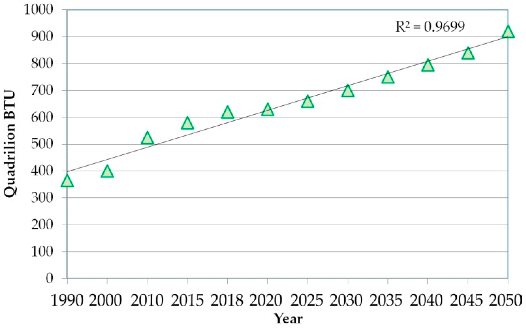
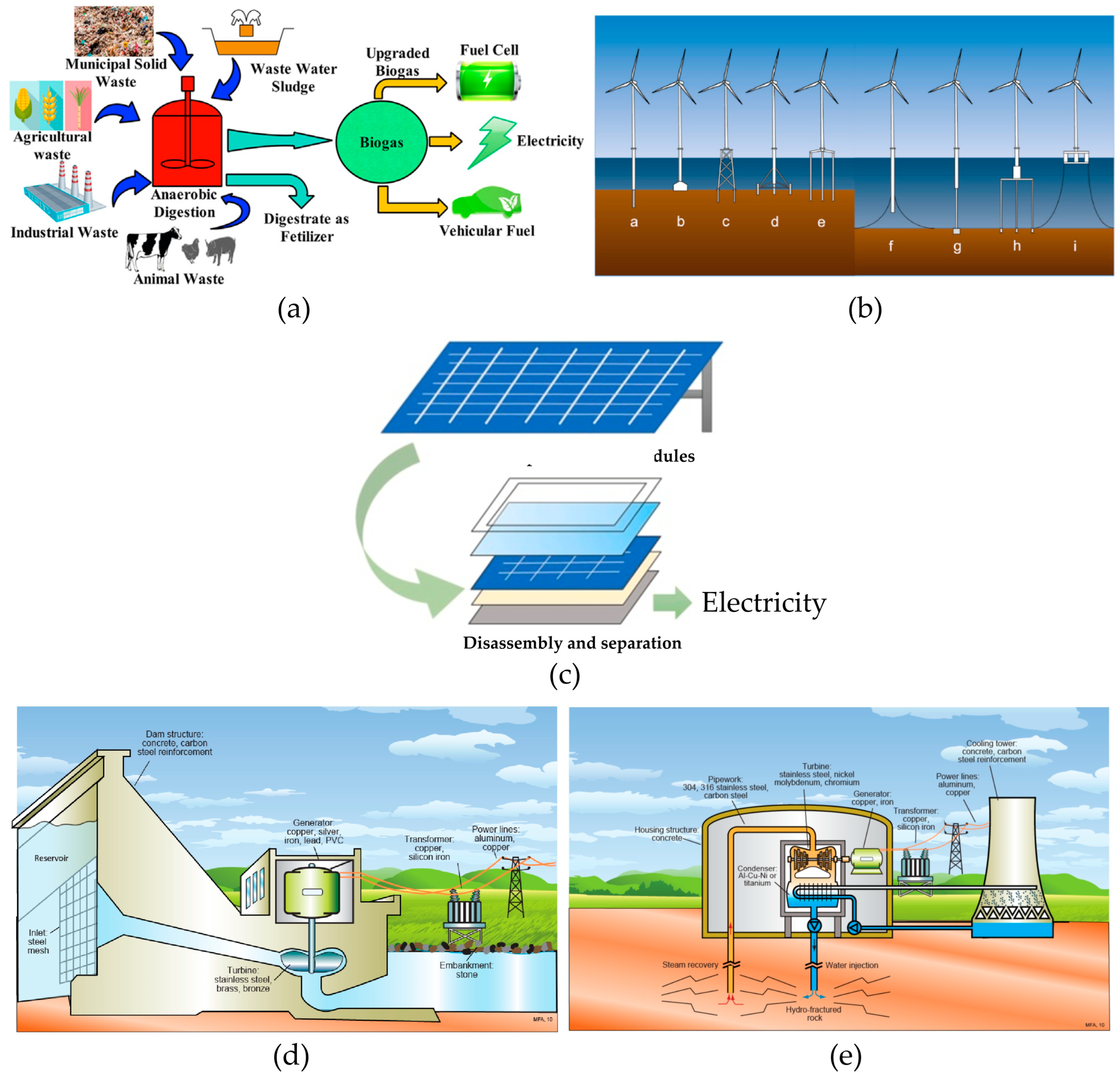
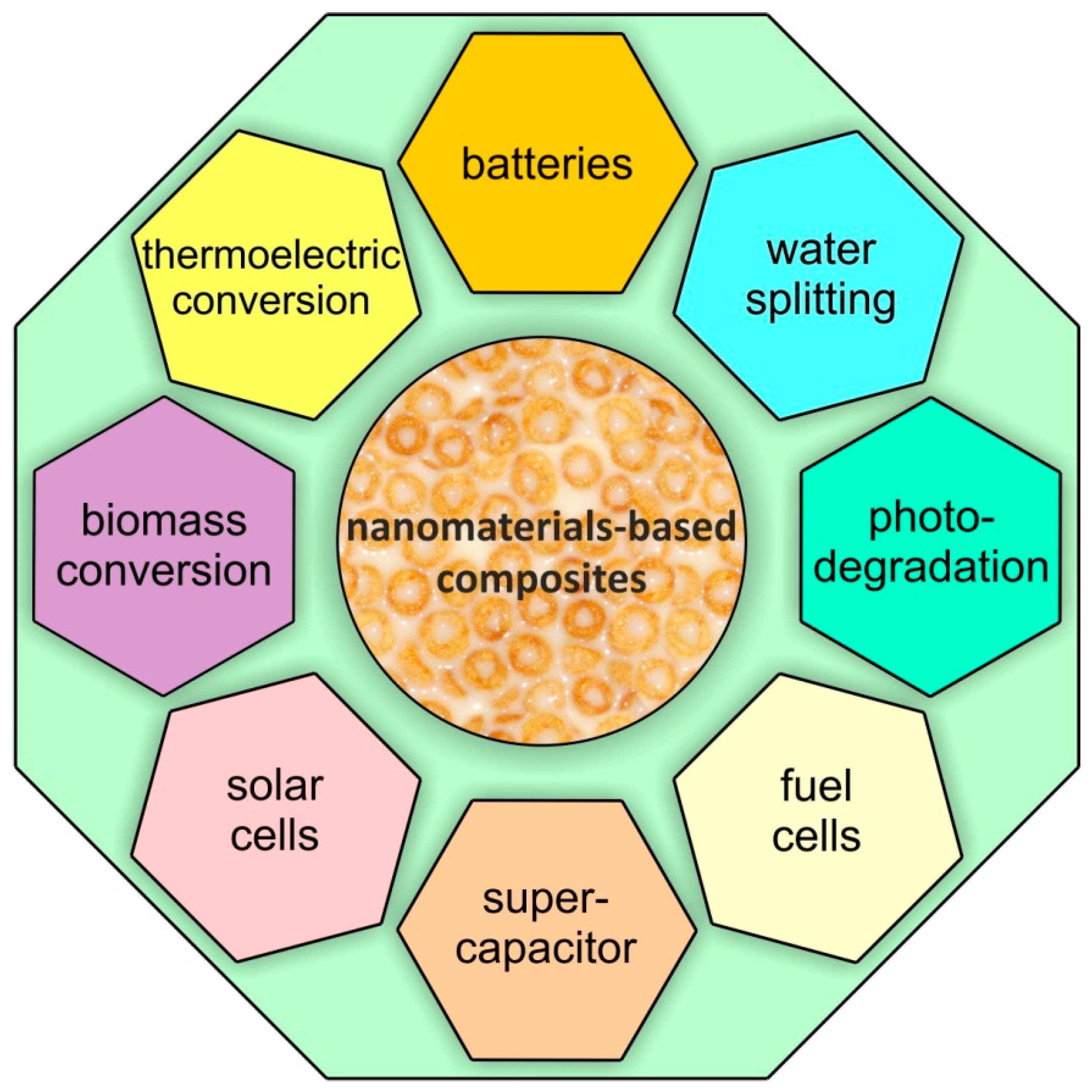
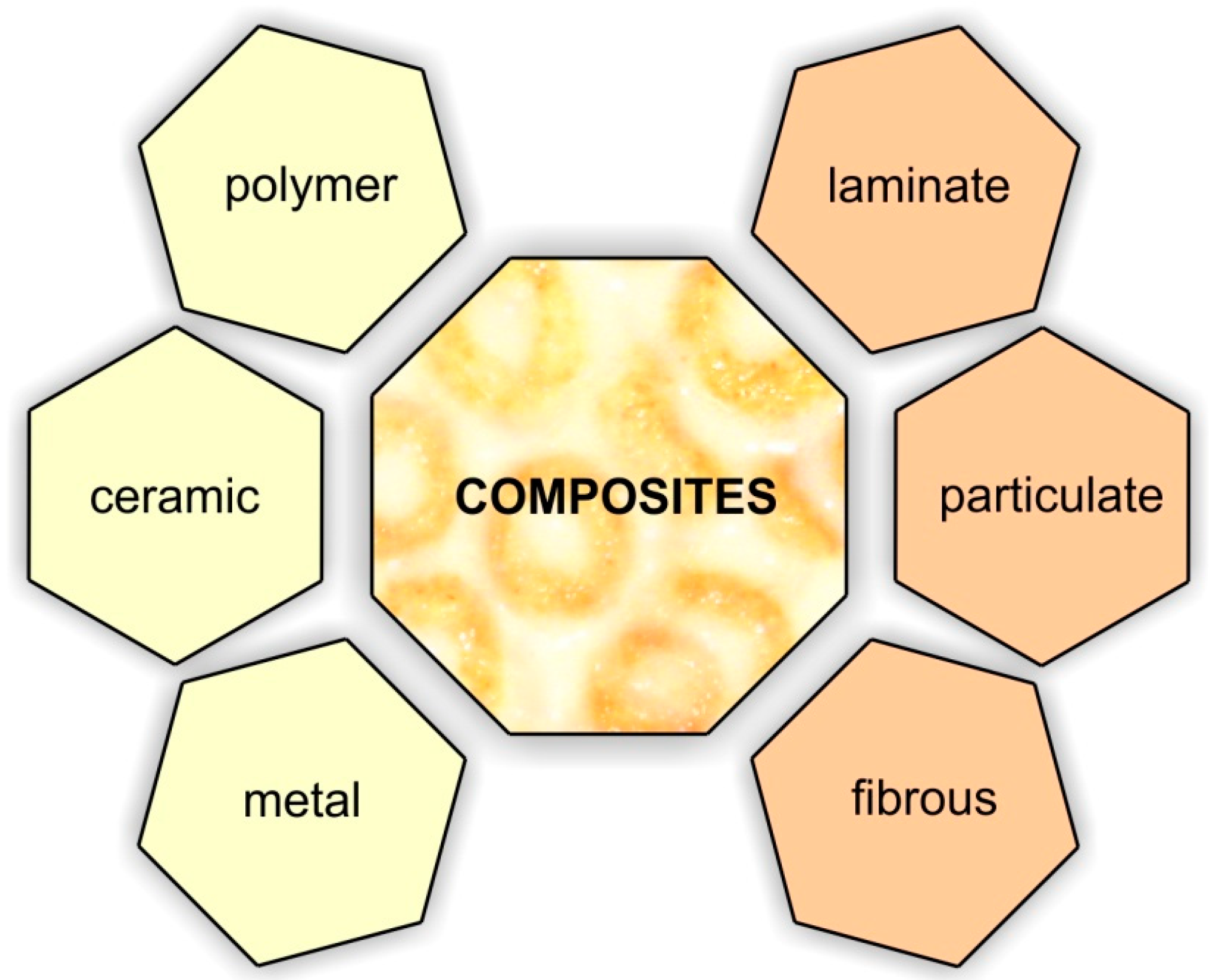
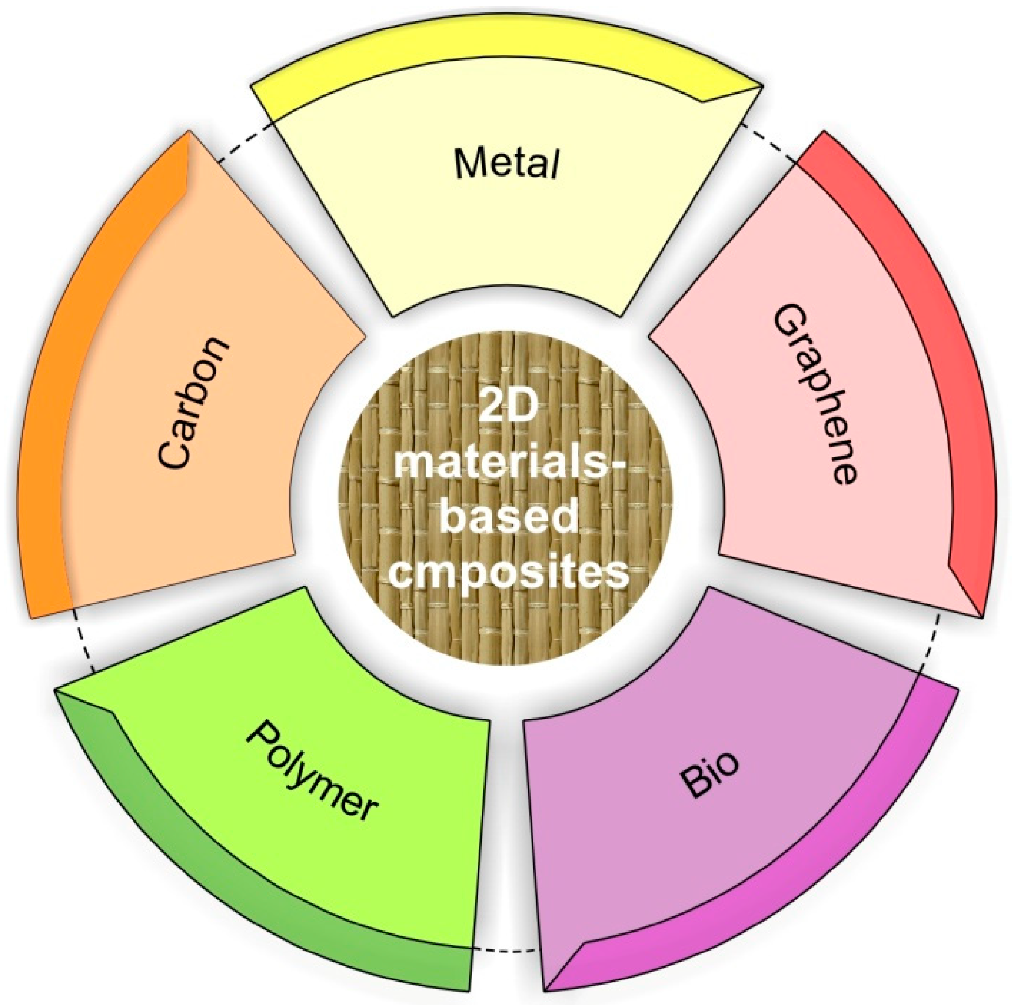
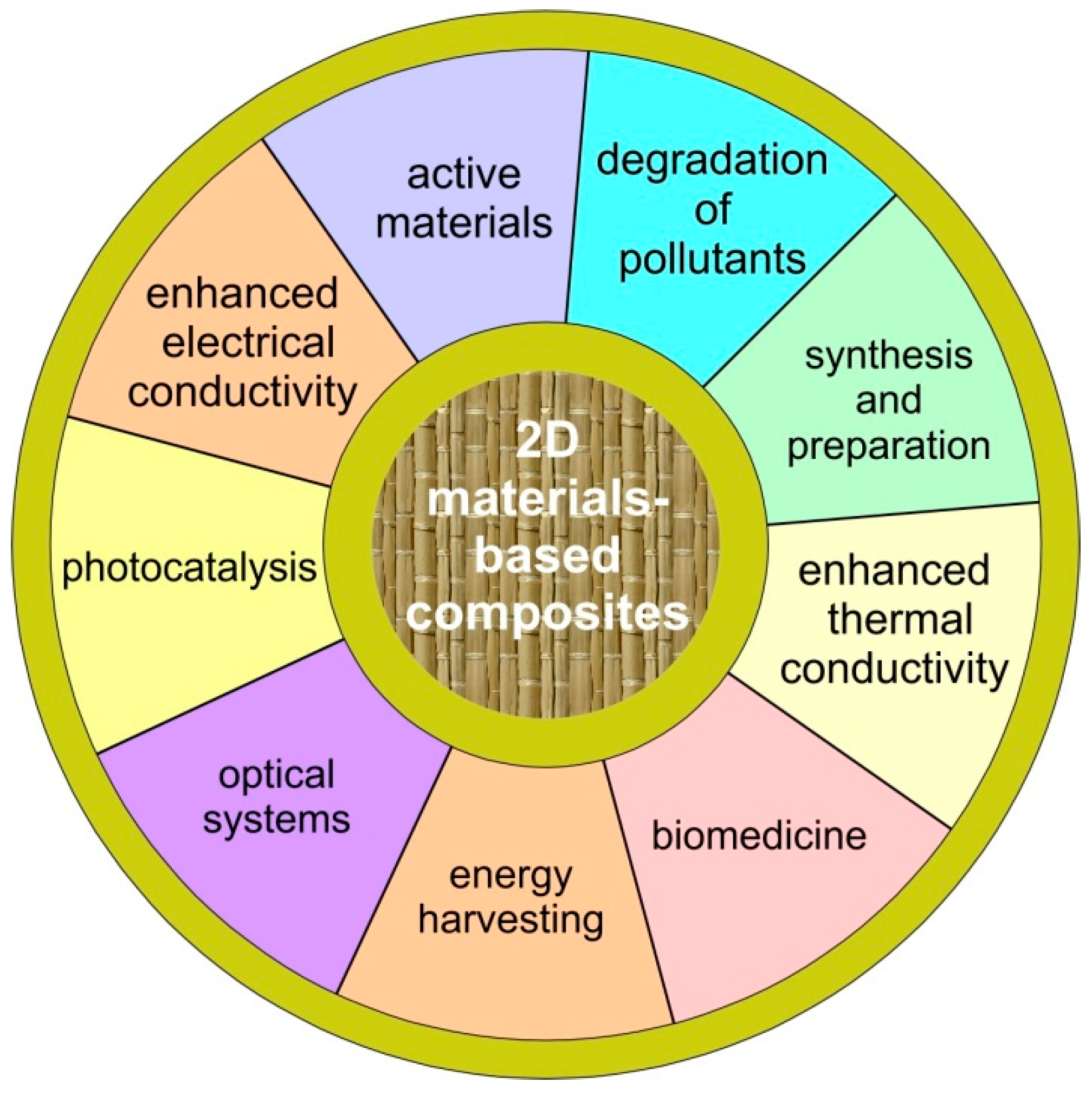
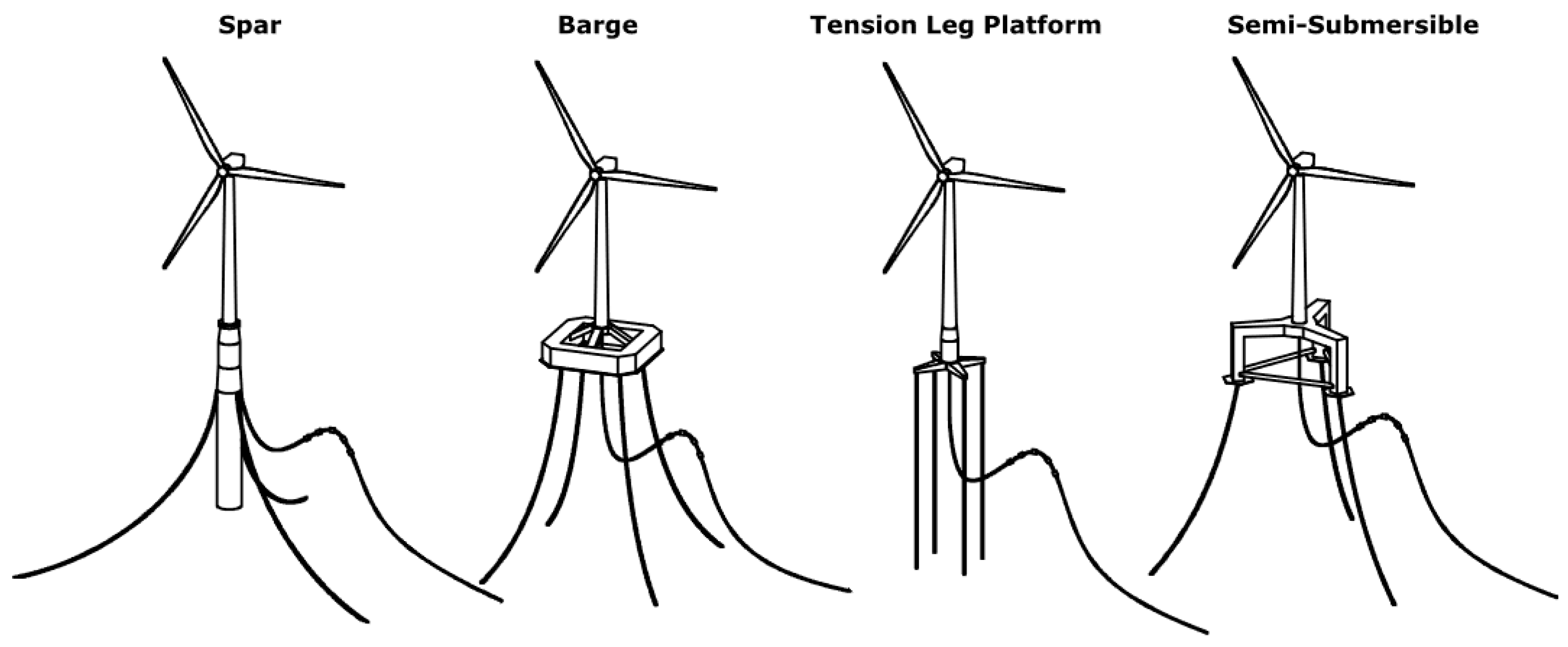
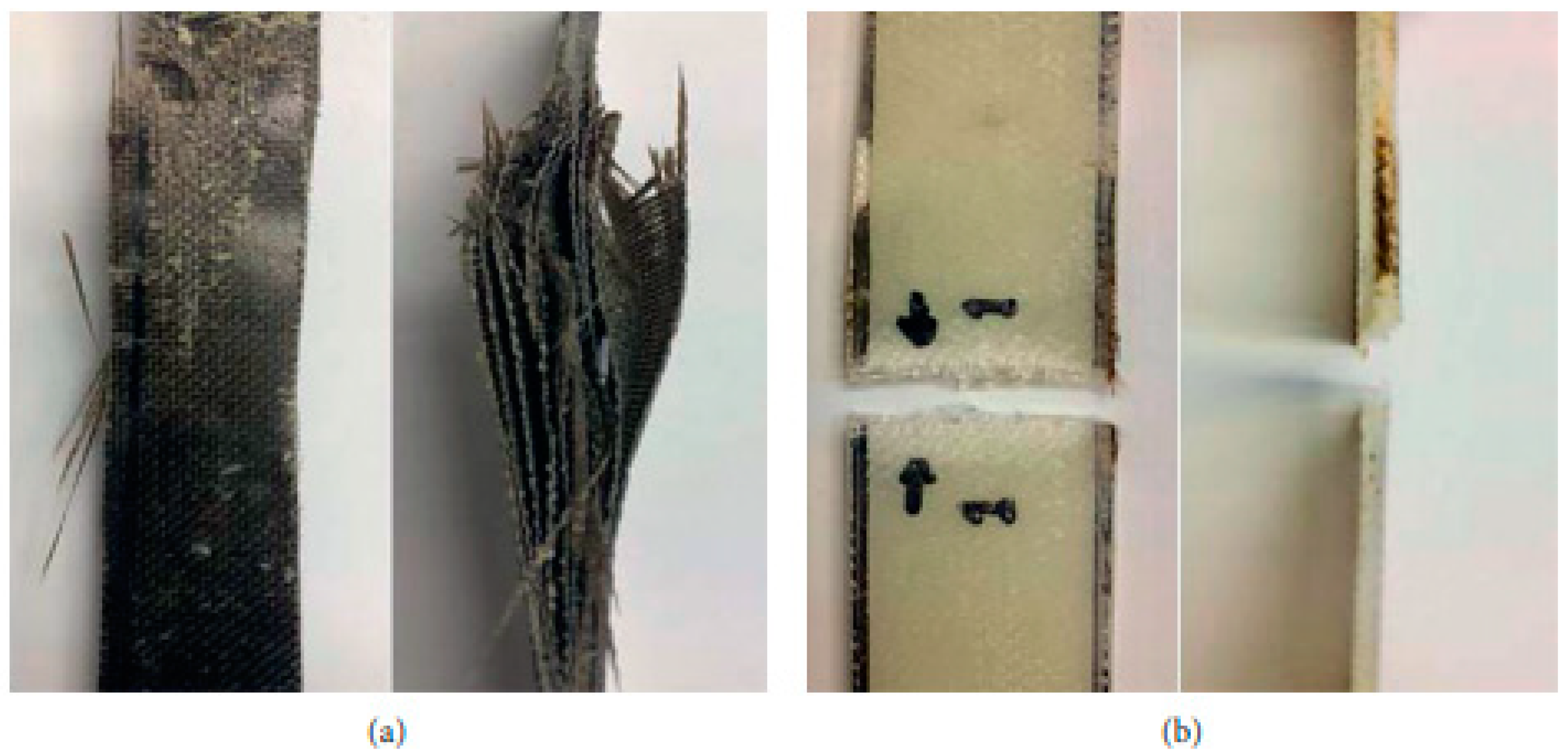
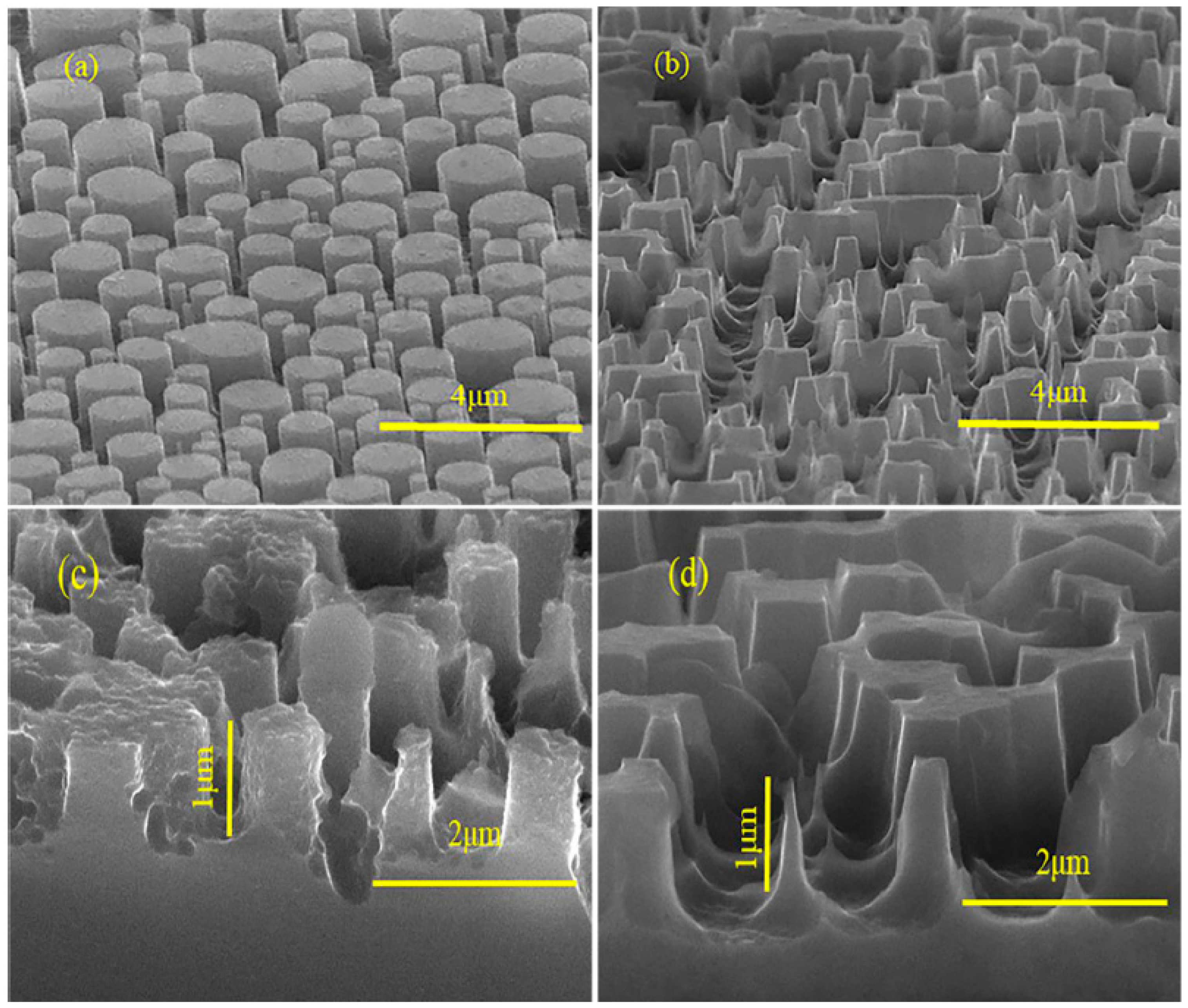
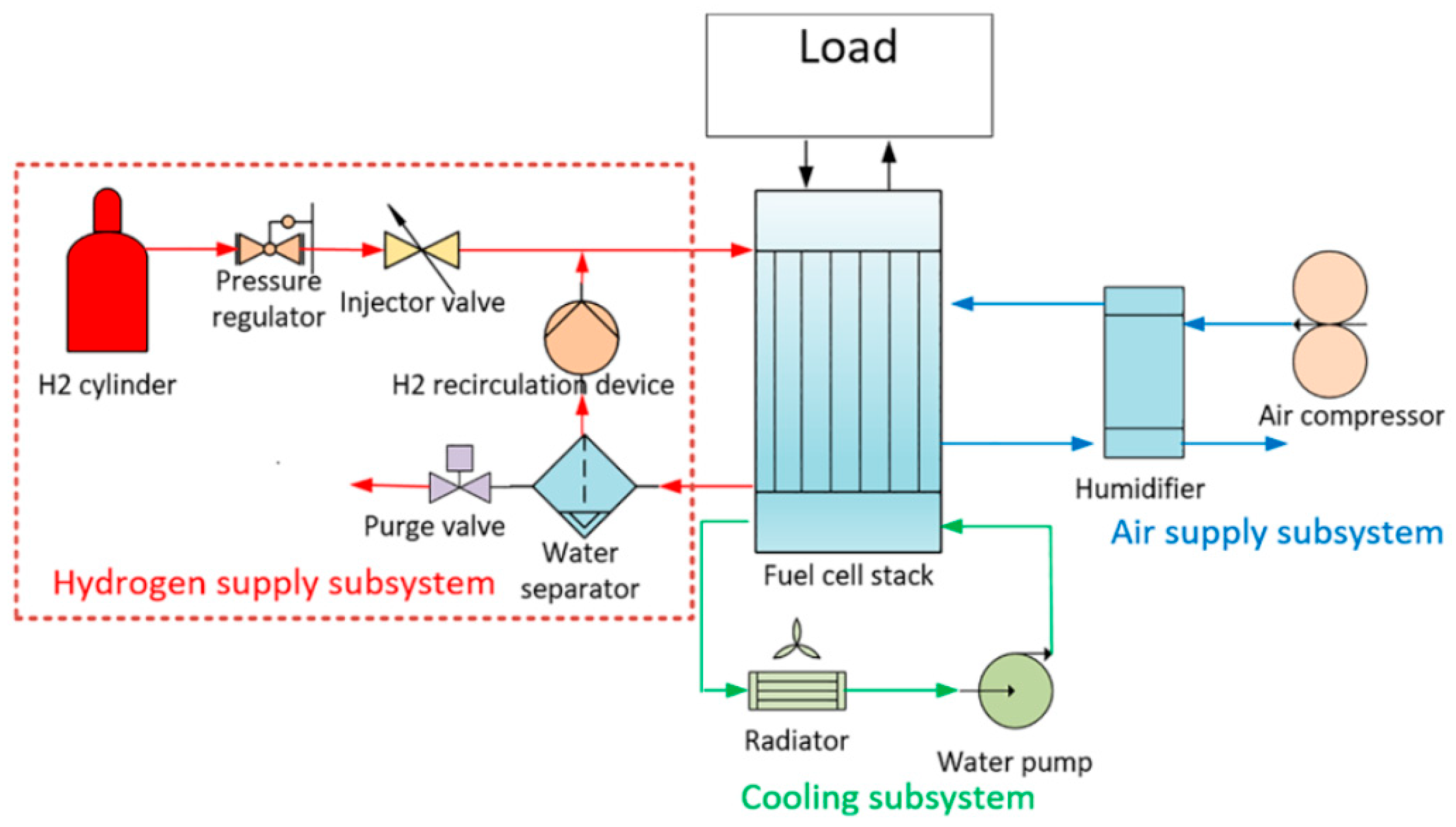
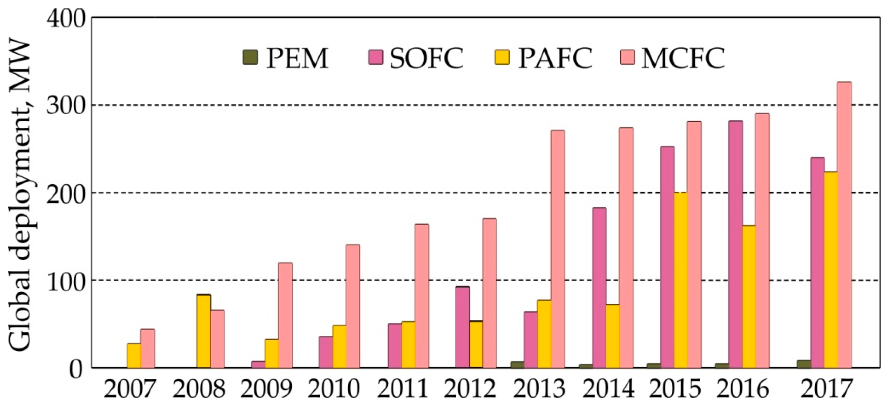
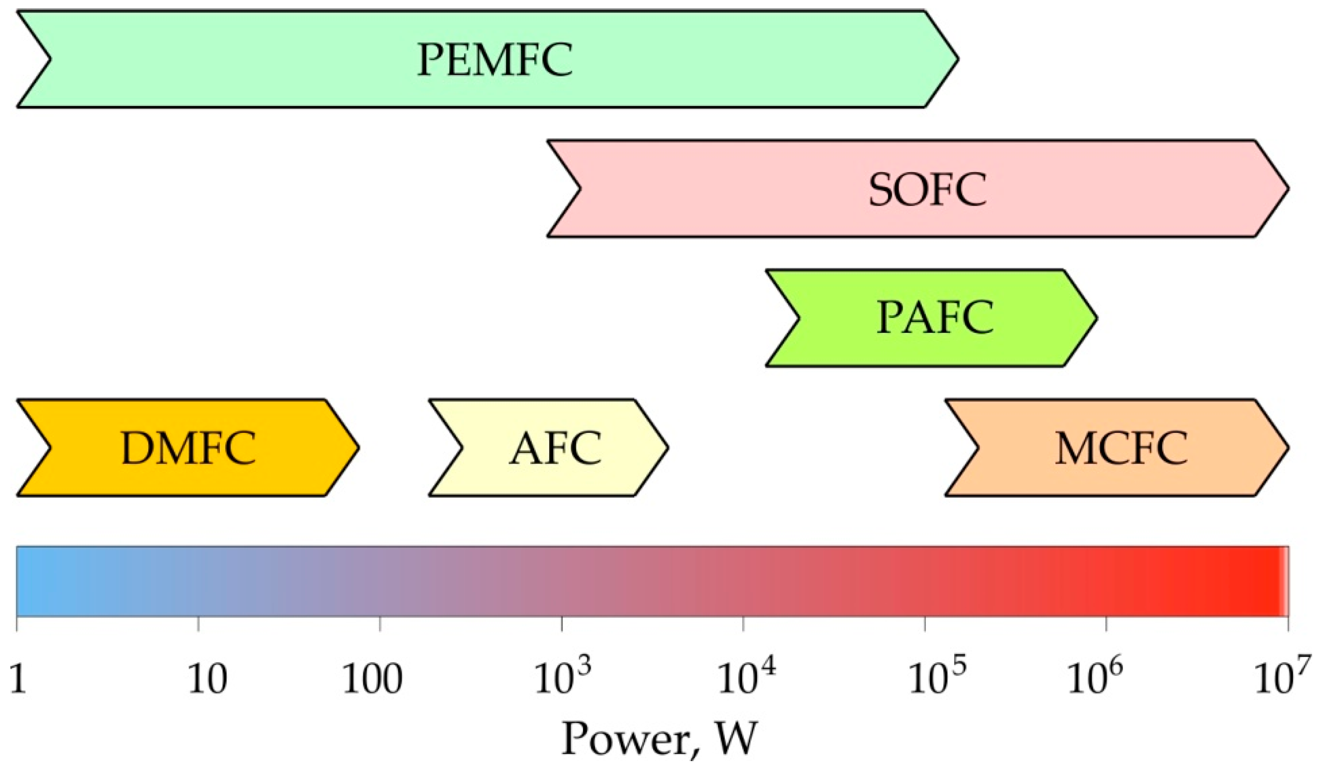
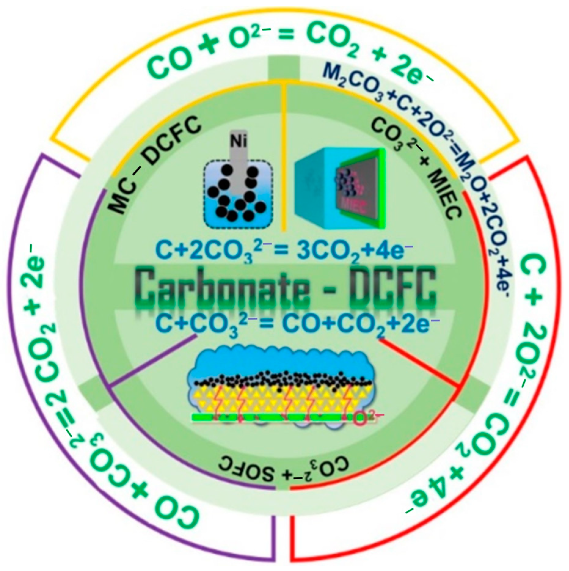
Table 1.
Properties of the fuel cells, prepared on the basis of [133].
Table 1.
Properties of the fuel cells, prepared on the basis of [133].
| Fuel Cell Type | Operating Temperature, °C | System Output, kW | Electrical Efficiency, % | Combined Heat and Power (CHP) Efficiency |
|---|---|---|---|---|
| AFC | 90–100 | 10–100 | 60 | >80 |
| PAFC | 150–200 | 50–1000 | >40 | >85 |
| SOFC | 600–1000 | 1–3000 | 35–43 | <90 |
| MCFC | 600–700 | 1–1000 | 45–47 | >80 |
| PEM | 50–100 | 1–250 | 53–58 | 70–90 |
| DMFC | 60–200 | 0.001–100 | 40 | 80 |
Table 2.
Main advantages and disadvantages of selected fuel cells.
| Fuel Cell Type | Advantages | Disadvantages |
|---|---|---|
| AFC | high energy density, less sensitive to impurities of the fuel, can operate at atmospheric pressure at low temperature, they are simple in structure, they have low costs of the electrolyte and catalysis | expensive catalyst, AFC is easily poisoned by carbon dioxide, AFCs exhibit problems with material durability issues, the electrolyte used is corrosive, they have high cost for commercialized applications |
| PAFC | high efficiency in cogeneration, phosphoric acid electrolyte can operate above the boiling point of water, PAFCs are CO2-tolerant | expensive catalyst, the electrolyte exhibits strong corrosive properties, when compared to other fuel cells of similar weight and volume, it produces less power, at lower temperatures phosphoric acid is a poor ionic conductor |
| SOFC | possible operation in cogeneration, there is no need for electrolyte loss maintenance | long start-up time, the relatively high cost and complex fabrication |
| MCFC | possible operation in cogeneration, they are not prone to poisoning by CO or CO2, they are more resistant to impurities than other fuel cell types | long start-up time, cell component degradation at high operating temperature, the electrolyte exhibits strong corrosive properties, high cost, not suitable for portable applications |
| PEM | a quick start-up process, light-weight packed system, flexibility in input fuel | if onboard hydrogen is used, it must be stored as a compressed gas in pressurized tanks; PEMs require an expensive catalyst |
| DMFC | carbon dioxide is a by-product, and it is released into the atmosphere | the efficiency is low, so the DMFCs are more suited for portable applications |
Disclaimer/Publisher’s Note: The statements, opinions and data contained in all publications are solely those of the individual author(s) and contributor(s) and not of MDPI and/or the editor(s). MDPI and/or the editor(s) disclaim responsibility for any injury to people or property resulting from any ideas, methods, instructions or products referred to in the content. |
© 2023 by the authors. Licensee MDPI, Basel, Switzerland. This article is an open access article distributed under the terms and conditions of the Creative Commons Attribution (CC BY) license (https://creativecommons.org/licenses/by/4.0/).
Share and Cite
MDPI and ACS Style
Trzepieciński, T.; Batu, T.; Kibrete, F.; Lemu, H.G. Application of Composite Materials for Energy Generation Devices. J. Compos. Sci. 2023, 7, 55. https://0-doi-org.brum.beds.ac.uk/10.3390/jcs7020055
AMA Style
Trzepieciński T, Batu T, Kibrete F, Lemu HG. Application of Composite Materials for Energy Generation Devices. Journal of Composites Science. 2023; 7(2):55. https://0-doi-org.brum.beds.ac.uk/10.3390/jcs7020055
Chicago/Turabian StyleTrzepieciński, Tomasz, Temesgen Batu, Fasikaw Kibrete, and Hirpa G. Lemu. 2023. "Application of Composite Materials for Energy Generation Devices" Journal of Composites Science 7, no. 2: 55. https://0-doi-org.brum.beds.ac.uk/10.3390/jcs7020055