1. Introduction
The significant integration of a large number of cores into the same chip for creating multi-/many-core Systems-on-Chips (SoCs) created new challenges for designers. The Network-on-Chip (NoC) paradigm has been promoted as a viable solution to deal with multi-/many-core emerging trends. Despite its strengths, NoCs have significant performance limitations due to the high latency and power consumption resulting from long multi-hop wired links used to deliver the data, especially in long-range communications across the chip. Several interconnect technologies have been proposed based on photonic, 3D, and Radio-Frequency (RF) to overcome this issue. Hybrid architectures were also introduced, combining multiple interconnect technologies.
Photonic solutions provide a way to reach near speed-of-light communications across on-chip wires [
1,
2]. These approaches achieve very low latency, but they face the problem of the considerable area dedicated to the signal conditioning circuitry. In this case, the optical NoC is introduced to enable high-speed links and negligible power dissipation. However, signal noise and waveguide losses are not negligible.
3D-NoC is an interesting approach to address the problem of the interconnection scale. This architecture responds to future multi-/many-core architectures’ requirements by exploiting short vertical links between adjacent layers to improve network performance [
3,
4] considerably. However, the advantages of this technology cannot neglect thermal problems as the number of layers increases.
Another approach based on radio-frequency waves is the RF-NoC interconnect. It provides flexible communication and single-hop long-range communication, aiming at reducing latency. This technology is based on the transmission of electromagnetic waves through the chip, allowing high bandwidth communication and low delay. Two types of radio-frequency interconnects exist, the first one making use of antennas and leading to free space communication (wireless), the other one exploiting communication using a waveguide (wired RF). The latter is similar to wireless propagation in terms of CMOS compatibility, high throughput, low overall power consumption, and near-light speed signals. Solutions using antennas have greater flexibility, but they also increase consumption and suffer from less immunity to interference when compared to waveguide [
5]. Besides, the waveguide provides a communication channel, perfectly known at the design phase. Moreover, design and sizing of RF elements for RF-NoC architectures based on waveguides have already been proposed in the literature, demonstrating the feasibility of the approach. The interested reader could find more details in [
6,
7,
8].
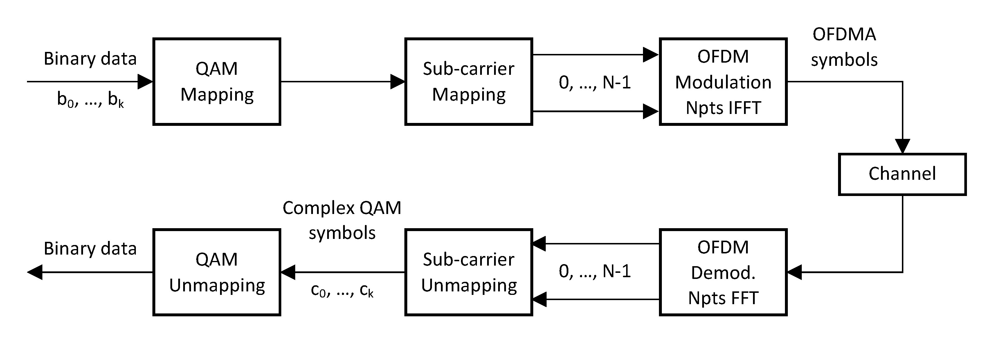
To take advantage of all the benefits of these new technologies, an efficient multiple access technique is required to share the spectrum resources among the different elements wishing to communicate. Many multiple access techniques exist, such as Frequency Division Multiple Access (FDMA), Time-Division Multiple Access (TDMA), and Wavelength Division Multiple Access (WDMA). To achieve high spectral efficiency, a multi-carrier modulation approach, namely Orthogonal Frequency Division Multiplexing (OFDM), is used. Among the significant advantages provided by OFDMA, it achieves high spectral efficiency and allows a flexible resource allocation while being a robust multi-carrier modulation against inter-carrier interference.
Regarding the NoC architecture, many parameters have an impact on power and performance. This is the case of the traffic occurring inside the NoC, which depends mainly on the applications running on the system. Synthetic traffics (e.g., Transpose Matrix and Random) are good choices for a first study but may not reflect traffics generated from real applications and scenarios. The NoC topology is also a crucial parameter. It leverages the choice of routing and selection algorithms as well as micro-architectural NoC parameters. All of these parameters have to be jointly considered when evaluating the performance of such architectures.
In particular, when adding a second interconnection layer based on RF, it becomes very complicated for a designer to make decisive choices that will ultimately have a relevant impact on power and performance figures. For example, the resource allocation strategy of RF interconnects, as well as the NoC routing policy, have to be finely defined to efficiently balance the traffic over the wired NoC or RF links.
Given the number of design choices, a need has emerged for simulation tools capable of simulating these emerging architectures. There are two main categories of simulators: (1) application-level simulators to analyze the behavior of a given application running on a specified multi-core architecture, and (2) Cycle-accurate NoC simulators, which perform fine-grained simulation of the NoC architecture, leading to more accurate power and latency results.
This paper introduces a simulation framework based on Noxim and Sniper simulators, enabling design space exploration for RF-NoC OFDMA architectures while considering real application traffic. The use of RF-NoC architectures with OFDMA brings some interesting advantages since OFDMA can adjust the channel usage to serve single o multiple users (the processing elements) simultaneously. In this sense, OFDMA is a very good option for low bandwidth applications, also thanks to the better frequency reuse and low latency. At best of our knowledge, there are no other simulation frameworks that allow the evaluation of such architectures by finely tuning the routing algorithm parameters for OFDMA RF-NoCs such as the ones introduced in [
9,
10].
The remainder of this paper is structured as follows. A comparative study of NoC simulators is presented in
Section 2. Then, the considered RF-NoC architecture based on OFDMA is presented in
Section 4, and the proposed framework is detailed in
Section 5. Simulations results are presented in
Section 6.1. Finally, conclusions are drawn in
Section 7.
2. NoC Simulators
Before proceeding with the hardware implementation or the emulation of a NoC design, the use of a simulation framework is almost mandatory. A good simulation framework, indeed, allows minimizing implementation costs through an early estimation of different figures of merit before the physical implementation of the system, helping in the process of making the right design decisions suitable for the considered scenario. Most NoC simulators are developed in C++ or SystemC, and some of them in Java. Simulators written in Java are usually high-level simulators. They offer better code portability but lead to less efficiency. Simulators can be classified depending on their accuracy (e.g., cycle-accurate, and discrete event-driven) or depending on their programming abstraction level (i.e., high/low). In the following, most adopted existing NoC simulators are introduced with a particular focus on Noxim.
Booksim is a cycle-accurate simulator written in C++ by Dally and Towles from the University of Stanford in the USA [
11]. Booksim is the first version not intended for a specific on-chip environment but mostly a generic simulator. This version was extended to overcome limitations in order to include some advanced features and technologies for on-chip networks. Booksim2 provides a wide diversity of topologies such as mesh, torus, tree, and butterfly. It supports a variety of routing algorithms and several options to customize the micro-architecture of routers to simulate.
DARSIM is a cycle-level, parallel simulator from the Massachusetts Institute of Technology (MIT) [
12]. It allows simulating both 2D and 3D mesh architectures. DARSIM provides a large advanced set of NoC parameters such as different virtual channel (VC) allocation and memory models. The simulator offers diverse routing algorithms due to its highly parameterized routing table-based, which provides two possibilities: running the simulation from application traces or synthetic patterns. One of the strengths of this simulator is the ability of the hardware configuration, such as bandwidth, pipeline depth, and geometry. Besides, it allows to split the tasks between cores equally and achieves cycle-accurate simulations.
HNOCS (Heterogeneous NoC Simulator) [
13] is dedicated to heterogeneous NoC architectures and is based on OMNet++. OMNet++ provides C++ APIs to a wide range of services to describe in detail the network topology. Moreover, the basic elements for the network configuration (routing algorithms/topologies/VC), HNOCS simulator provides parallelism, various Quality-of-Service (QoS), different arbitrary technologies, and power estimation. It offers three different router types, asynchronous, synchronous, and synchronous virtual output queue and performance statistics such as throughput, VC acquisition, and transfer latency.
Nigram is a cycle-accurate and discrete event simulator developed in SystemC by the Malaviya National Institute of Technology India and the University of Southampton UK [
14]. It provides various network configuration commands to simulate different NoC architectures such as routing algorithms (source, XY, odd-even, adaptive), topologies (Tree, Torus, Mesh, and Ring), two flow control techniques (deflection and wormhole). The simulation statistics include throughput and latency.
Noxim is developed by the group of computer architectures at the University of Catania [
15]. It is a low level, open-source, and cycle-accurate simulator written in C++/SystemC. Noxim provides various configuration parameters such as packet and buffer sizes, packet injection rate, different routing algorithms (XY, Odd-Even, West-first, North-last), traffic distributions (Random, Transpose, Bit-reversal, Butterfly Shuffle, Table Based traffic, hotspot), structures, and topologies. In addition to the wired NoC simulation, Noxim also supports Wireless NoC (WiNoC) evaluation and provides power consumption, throughput, and latency as performance analysis. Access Noxim is an extended version that supports 3D NoC architecture and adaptive routing [
16].
Orion 3.0 is a simulator dedicated to evaluating the power performance of the NoC. It provides component dynamic and leakage power models. Orion3.0 [
17] overcomes the limitations of the Orion simulator by supporting power models estimated from actual post-placement and routing layout and area.
SunFloor-3D is the extended version of the SunFloor simulator. SunFloor is able to generate a system specification that allows designing NoC architectures from a set of defined input constraints (energy, area, and model). SunFloor-3D is dedicated to 3D-NoC architectures [
18] and provides many advanced features such as the placement of components in the 3D layers. It enables the characterization of the core assignment and communication bandwidth.
3. System Simulators
In the following, the two most adopted system-level simulators, namely Gem5 and Sniper, are introduced with a particular focus on Sniper, which, together with Noxim, has been chosen to evaluate the considered RF-NoC architecture.
Gem5 is one of the more general simulators that come to the aid of computer architecture researchers. It is the result of the combination of two simulators GEMS [
19] and M5 [
20]. GEMS provides a flexible and detailed memory system and multiple cache protocols. GEMS simulator supports many commercial Instruction Set Architectures (ISAs) such as x86 (64 bits), MIPS, ARM, ALPHA, SPARK, and PowerPC and implicates Linux boot on ARM, ALPHA, and x86. Gem5 [
21,
22] also includes the best features of M5, especially the highly configurable environment to simulate various processor models. Specialized versions of Gem5 exist, for example Gem5-gpu [
23] which is a simulator dedicated to heterogeneous CPU-GPU.
Sniper is a multi-core simulator based on the infrastructure of Graphite [
24]. Sniper allows parallel, fast and accurate simulations and supports both homogeneous and heterogeneous multi-core architectures [
25]. The principal simulator feature is the core model based on interval simulation. Sniper is considered as a high-speed simulator due to the interval simulation, which raises the abstraction level. It is useful for core and system-level studies that need details more than the typical one-IPC models. It includes SPLASH-2 (Barnes, Cholesky, FFT, FMM, Lu, Ocean, Radix, Radiosity, and Raytrace) and Parsec (Blackscholes, Bodytrack, Canneal, Dedup, Facesim, Ferret Fluidanimate, Freqmine, Raytrace, Streamcluster, Swaptions, VIPS, and x264) benchmarks in order to evaluate the NoC architecture. Sniper also provides SimAPI interfaces and Python to monitor and control its behavior at run time.
This section, together with the previous one provided a comparison of simulation tools to help decide on the suitable simulator regarding NoC designs and proposals starting from both NoC-/system-level available simulation tools. Each of these tools has its own peculiarities when adopted in a standalone or combined fashion. For example, Booksim2 provides a highly flexible simulation environment that allows fine-grained management of many elements, such as buffer size, virtual channels, and routing algorithms, and Gem5, coupled with Garnet2.0, offers the support to Full System (FS) simulations.
Table 1 and
Table 2 summarize the different NoC and system simulators, respectively. These simulators, detailed above, are just a representative set of the existing possibilities taken into account in this research. By the way, no simulator found in literature includes all evaluation criteria at the same time. The proposed framework, detailed in
Section 5, is based on two simulators: Noxim and Sniper. Noxim has been preferred to other NoC simulators since it already supports Wireless NoC architectures. Therefore, it offers an already established starting base and core elements such as Radio Hubs to simulate long-distance, single-hop communications. Also, Noxim comes with a tool, namely noxim explorer, that helps the user run batch simulations after defining the ranges of values for the simulator’s parameters. Radio Hubs and Noxim Explorer have been extended to support the use case presented in the submitted manuscript. For what concerns Sniper, it has been chosen for its flexibility, the availability of its SimAPI to control the simulator’s behavior at run-time, and the fact it allows tracing the traffic of real applications running on multi-core NoC-based architectures.
5. Proposed Framework
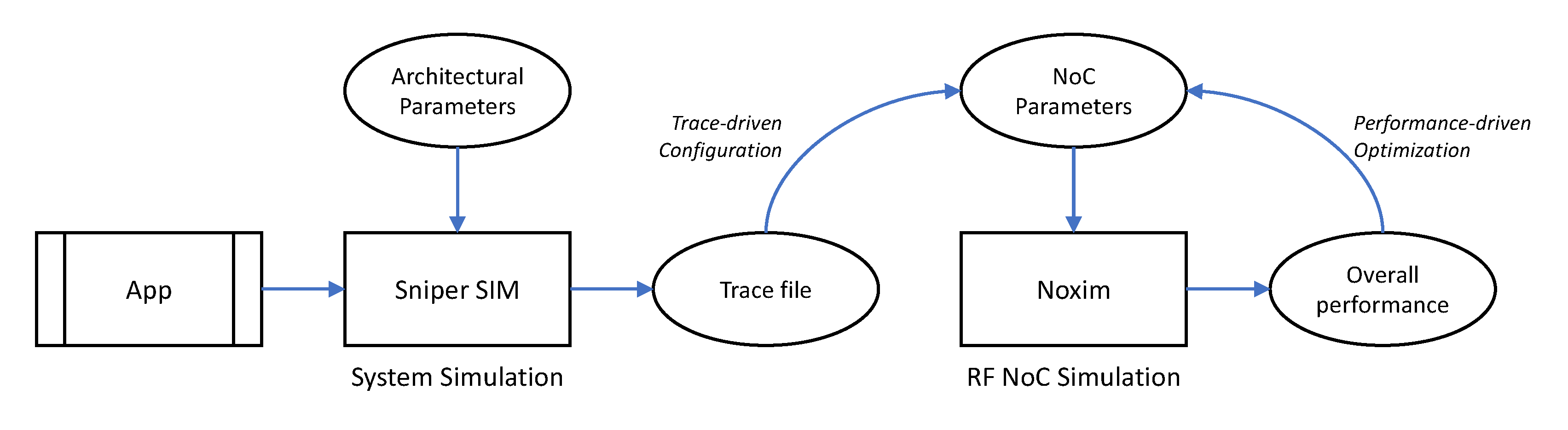
In this section, we detail the proposed framework, depicted in
Figure 4, which is specific for the performance evaluation of RF-NoC architectures. This framework is based on the combination of two existing simulators: Sniper and Noxim. We selected Noxim as in its released version it already supports wireless communications thus its extension to RF-NoCs allows us to have in the same framework the availability of three different NoC architectures, namely, traditional wired NoC, heterogeneous wired WiNoC, and heterogeneous wired RF-NoC. In addition, to obtain the communication patterns generated by an application, it needs executing the application on a multi-core simulator and tracing all the communication flows induced during the execution of the application. To this end, we used Sniper.
5.1. Sniper NoC Configuration
The major exploited benefits offered by Sniper are the integrated benchmarks that enable fast tests with common tasks, the possibility to write custom test applications, and the full details of the interconnection network, core models, and cache. Sniper was thus used to model our NoC topology and to obtain communication traces from real application benchmarks. Sniper includes several folders that provide built-in tools and configuration files for the simulation parameters. The main folders used in our framework are:
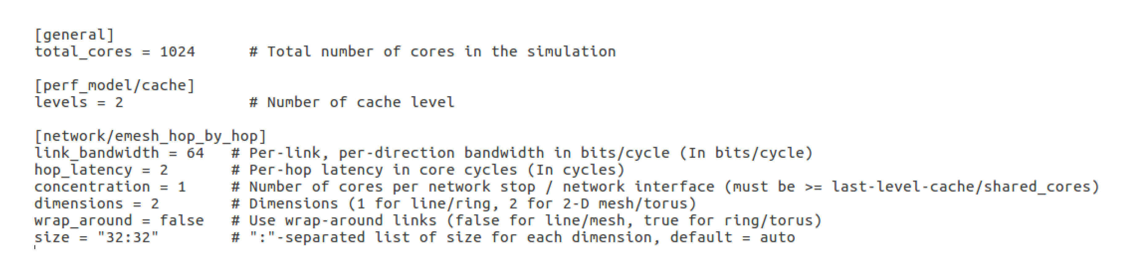
config which contains the NoC configuration file that describes the network to be simulated.
Figure 5 gives an example of NoC configuration specifying the number of cores, memory cache levels, network topology, cores concentration, and bandwidth in bit per cycle;
Benchmarks, which contains various benchmarks such as those from SPLASH-2, PARSEC, and SPEC CPU®2006 sets.
test in which a set of applications to evaluate the network such are collected. The initial set of applications come from Sniper (e.g., FFT) but it is possible to add the custom applications to test; Finally
tools folder includes python-coded tools to analyze simulation results.
After providing the NoC configuration file with all network parameters and the chosen application, Sniper produces a set of output files containing (i) general information related to the simulation (sim.info), (ii) the final configuration of the simulated architecture (sim.cfg), (iii), the results of the simulation in the form of a table (sim.out), and (iv) other statistics related to the execution (sim.stats).
5.2. Trace File
Results provided by Sniper are not directly exploitable by Noxim. Thus, we developed a python script to format the output results provided by Sniper for Noxim properly. In more detail, Sniper provides a tool called SIFT that allows for trace recording. We extract the communication statistics from this trace file and generate the appropriate traffic-based routing table for Noxim.
In more details, firstly, the total number of exchanged packets between cores per link and the number of cycles are extracted. Secondly, the packet injection rates per link are computed, to finally generate the corresponding routing table.
To calculate the packet injection rate for each source/destination pair, we use a tool provided by Sniper, namely
dumpstats, which provides simulation statistics. After the statistics have been stored in a file, the information regarding the timing and size of each communication is parsed by a python script introduced to extrapolate the number of packets
P exchanged per link as well as the number of cycles
C for each core to get the actual PIR (Packet Injection Rate) using the following equation:
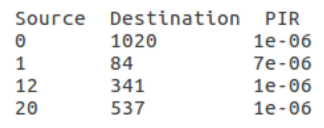
From these statistics, the total number of communication occurring inside the RF-NoC is easily derived. The python script, proposed for PIR’s evaluation, is then able to generate the traffic table. This traffic table is a text file in which each line represents the communication between a source and a destination and their associated PIR.
Figure 6 shows an example of a few lines of the generated traffic table. This format of the traffic table is supported by the Noxim simulator. From the user point of view, all the previous steps are automatically done by the framework.
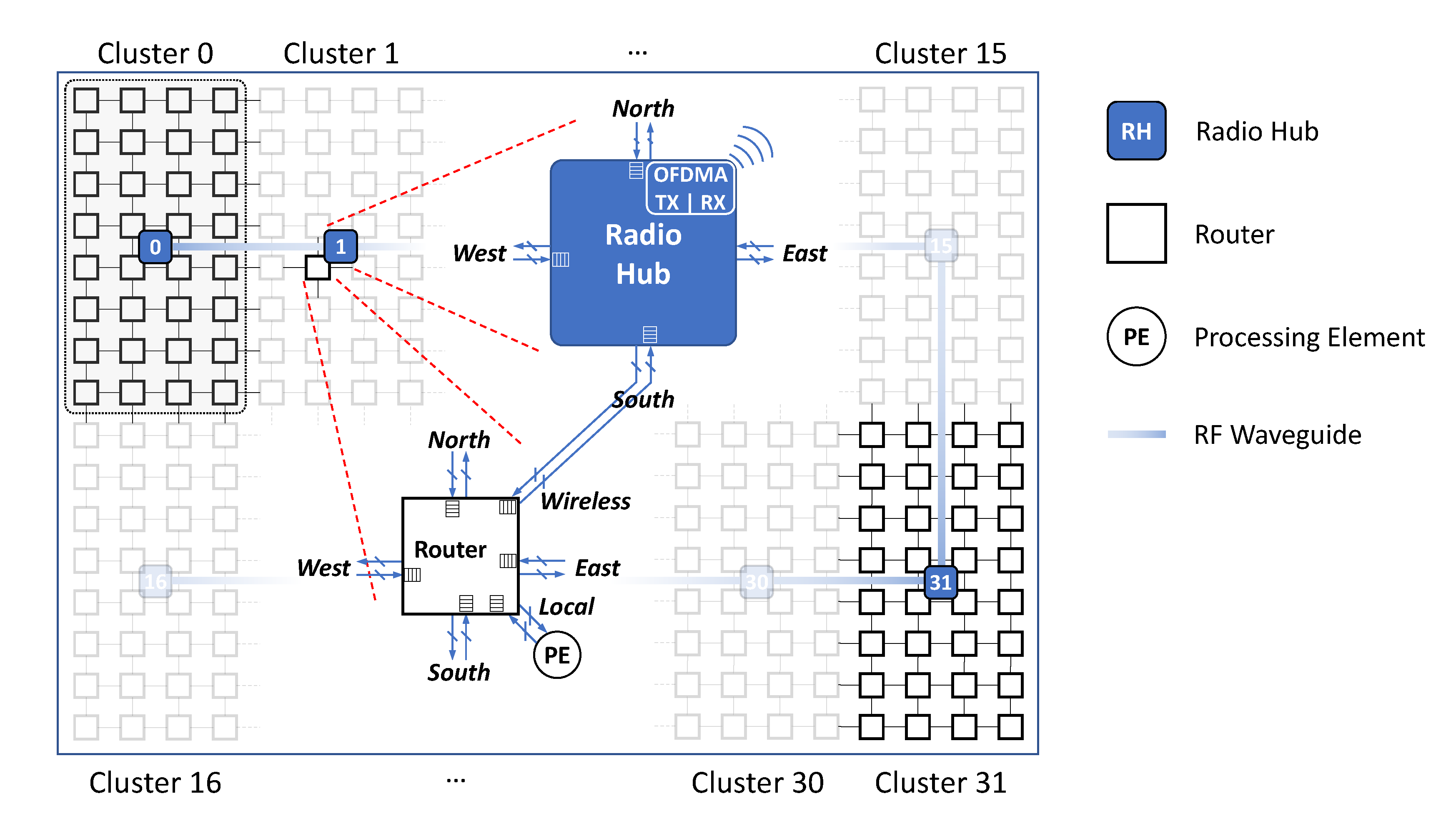
5.3. RF-NoC Simulation under Noxim
The choice of Noxim simulator is based on its capability of supporting WiNoC topologies. It includes a fundamental component of wireless interconnects which is the radio-hub. The radio-hub allows single-hop links between faraway nodes in order to avoid multiple wired hops. It provides also the channel component which abstracts a flit transmission using a given wireless frequency. Noxim makes use of the Transaction Level Model (TLM) to simulate wireless communications. It provides also an energy model that includes both wireless and wired energy consumption. However, OFDMA is not supported natively. This will be detailed after. To perform simulations using Noxim, a YAML configuration file that contains all NoC parameters has to be filled. This file is divided into four parts: in (i) Topology and Structure are defined all necessary details of the components for the considered NoC architecture, such as the number of cores, router buffer size, radio-hub configuration (attached nodes, buffer size, access technique), and channel data rate (bit/s). Then (ii) the Workload part contains various data traffic models (uniform, butterfly, transpose, hot-spot), the packet injection rate, and the packet size. The parameters, such as the routing algorithm, channel access technique, and the choice between wired/wireless communication, are defined in part (iii) Dynamic behavior. Finally, the Simulation section collects parameters regarding the simulation setup itself, such as the number of cycles, warm-up time, reset time, and the level for statistics details. In addition to the traffic models provided by Noxim, it gives the possibility to simulate a real application by mapping its communication graph into custom table-based traffic. This table-based traffic allows defining the source/destination pairs with the packet injection rate, its statistical distribution, and traffic volume to be injected. Thanks to this feature, we can easily use in the proposed framework the generated traffic table detailed above, which is supported by Noxim.
After defining Noxim inputs in accordance with Sniper configuration, the simulator provides a set of performance statistics at the end of each simulation in order to evaluate the simulated architecture. In particular, they are:
received packets, that reports the total number of packets effectively delivered at their destinations; the
average communication delay, calculated as the difference between the clock cycles in which the packet is generated and consumed by the destination, respectively; the
network throughput, defined as the ratio between the total received flits and the simulation duration in clock cycles. Finally,
energy consumption summarizes the energy consumption of links, routers, radio-hubs, and network interfaces. Starting from the existing features, Noxim was extended to support RF-NoC OFDMA architecture. Noxim implements the token-ring technique to access the radio channels, and only one radio hub can transmit information on the wireless link at a time. As a consequence, we extended Noxim to support OFDMA and concurrent accesses to wireless channels. In addition, the threshold-based routing algorithm in
Section 4.3 was also integrated into the simulator. Noxim provides a tool called
Noxim explorer which is dedicated to the design space exploration. It allows for the execution of a set of simulations with different configuration parameters. We extended
Noxim explorer to perform various simulations with different threshold values and consequently study the impact of threshold to the topology and the traffic distribution.
Regarding input Noxim parameters, some of them are directly defined according to Sniper configuration file, such as the number of cores, the topology, link bandwidth, etc. However, the user could still define other NoC architectural parameters as well as RF-related parameters e.g., number of sub-carriers, total frequency bandwidth, etc.
6. Performance Evaluation and Experimental Results
The traffic distribution strongly affects the performance of the network. In this part, we compare the results of synthetic traffic natively included in Noxim and the results obtained using the proposed framework, which integrates traffic generated from a real application. This comparison aims to validate the accuracy of the framework and draw conclusions about the choice of the threshold value for different application scenarios and different topologies. Moreover, this framework aims at showing the interest of automatically support real application traffic during design space exploration of OFDMA-based RF-NoC.
6.1. Synthetic Traffic Results
We define three different application scenarios according to the amount of long-distance communications, namely scenarios 1, 2, and 3, with their respective percentage of long-distance communications 75%, 50%, and 25%. This approach allows to classify the results according to the traffic pattern. In addition, to have a fair comparison between synthetic and real traffics, the total number of communications inside the RF-NoC remains approximately the same for all the experiments. This lets us study the impact of the threshold value most efficiently. From the following application specifications and the NoC topology, we generated a table-based traffic, depending on the network size, the number of hops to discriminate between short and long-range communications, and the packet injection rate, using a custom python script. Note that, for the considered topology, we define a communication as “long-distance communication” when the distance from the source to destination is greater than 8 wired hops, and then it is not necessary to exploit the RF link between adjacent clusters. The generated table-based traffic is used as input for Noxim.
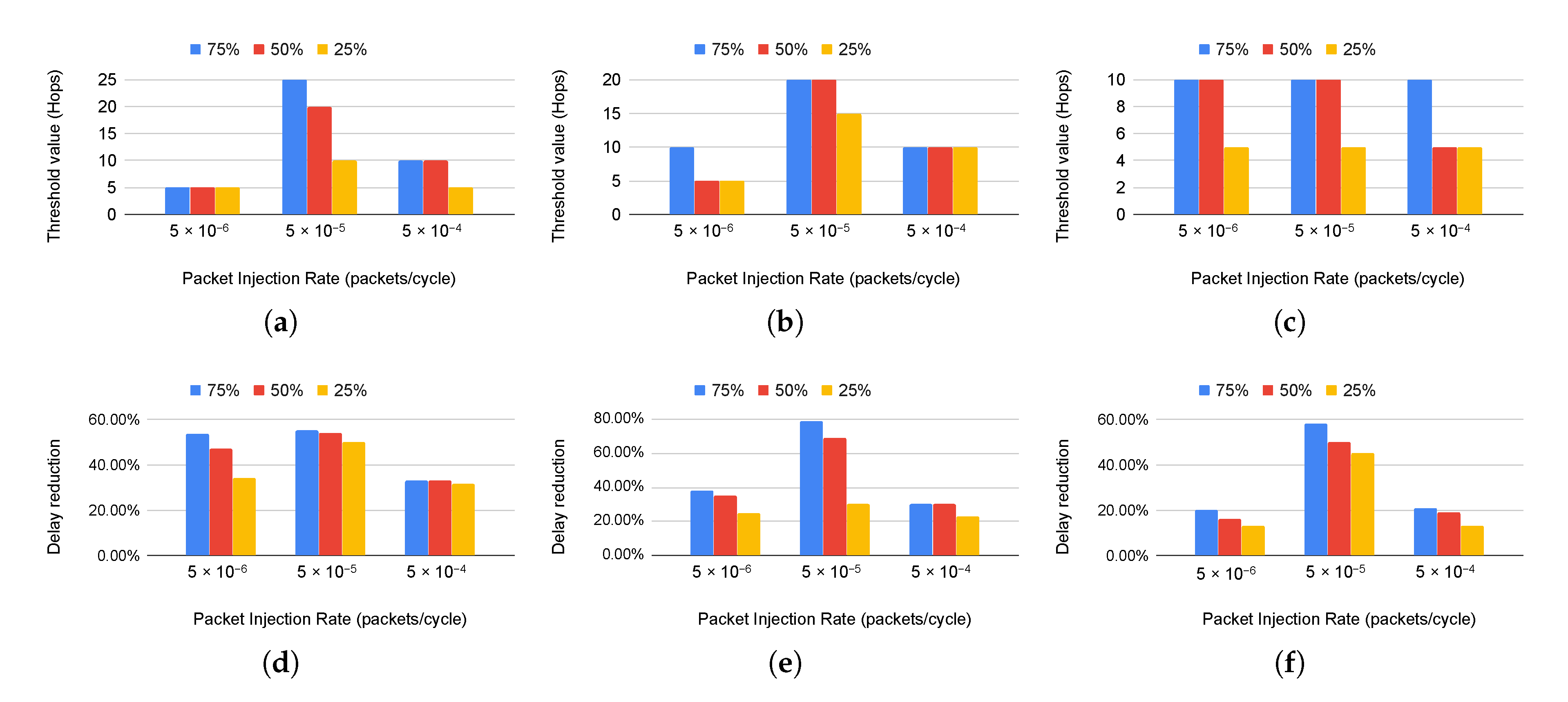
Figure 7 reports threshold values for
,
and
RF-NoC architectures under the three different traffic scenarios, with their respective delay reductions. We choose three different packet injection rate values to study the evolution of the threshold and the delay reduction value under different traffic loads. In these results, the total number of communications is
, which is similar for the real application traffic generated from Sniper and the synthetic ones, and all communications have the same packet injection rate. This total number of communications remains constant to have a consistent comparison. The reported threshold for different PIR values and different topologies in the following results refers to the appropriate threshold to reach the maximum network delay reduction.
Starting from the architecture results, we notice that for a PIR of , the threshold remains constant (5 hops) regardless of the scenario, and the delay reduction is about 53% for the first scenario with a slight decrease for other applications. Then, the threshold value increases for PIR equal to , with values of 25, 20, and 10 hops for the scenarios with 75%, 50%, and 25% of long-range communications, and we reach a significant delay reduction. Finally, for PIR equal to , we observe that the threshold and the delay reduction are decreasing because the network enters in the saturation zone and is no longer able to manage the traffic load. We notice that the latency reduction decreases with the percentage of long-distance communications; for example, for a PIR value of , we achieve 53% of delay reduction in the first scenario and 33% in the third application scenario.
For the architecture, it can be seen that we have the same trend with a slight degradation of the threshold value and we reach a delay reduction of 79% in the case of 75% long-distance communications for a PIR equal to . For this same PIR value, we notice that this topology allows achieving better latency reduction compared to topology under the first traffic scenario.
From the results of
architecture, we can see that the threshold decreases with the network size
Figure 7c. This value is between 10 and 5 hops for this topology for different application scenarios and PIR values. We can also note that the delay reduction is less significant for this architecture, particularly for low PIR values, i.e.,
and regardless of the type of traffic.
The presented results show that the threshold value is impacted by the application scenario, which refers to the percentage of long-distance communications in an application, and the traffic load, represented by the PIR value. These results also give an idea about the percentage of latency reduction that could be achieved compared to a wired NoC, which helps to decide on the use of the RF link and topology choice.
6.2. Design Space Exploration
In this section, we present an example of a design space exploration using the proposed framework. Following the steps shown in
Figure 4, we chose Splash2-FFT as benchmark provided by Sniper to evaluate three different RF-NoC topologies
,
and
.
Table 3 includes simulation parameters. Then, we generate the corresponding traffic table for Noxim to get performance statistics. Finally, the following results illustrated in
Figure 8 were obtained.
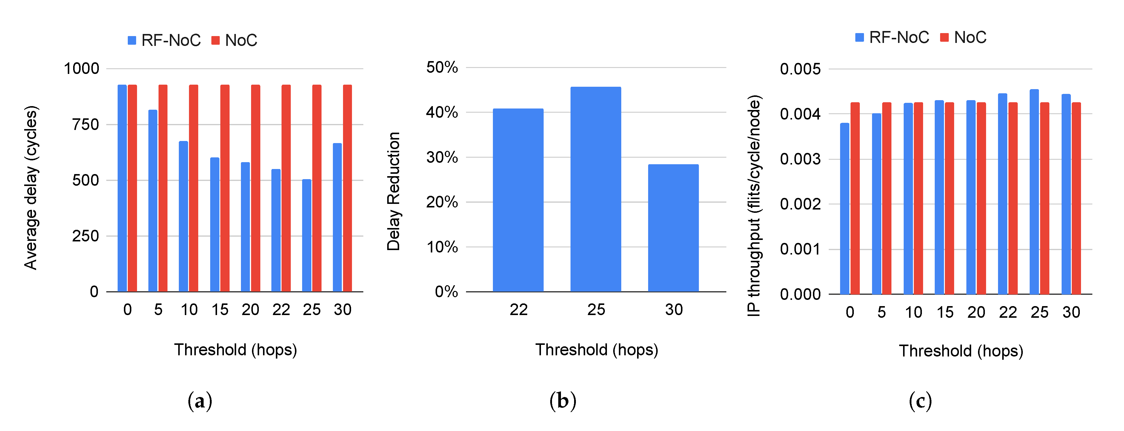
Figure 8a shows the average delay of both wired NoC and RF-NoC for different threshold values. We notice a high latency when the threshold is between zero and five hops, which reflect the overuse of the RF link. The RF utilization is about 85%, with a threshold value of zero. It means that most of the packets are routed towards the radio hubs, which leads to network congestion. However, the latency gets reduced in a significant way when the threshold increases until it reaches the value of 25 hops. This threshold value leads to a delay reduction of 45%, as shown in the graph depicted in
Figure 8b, which confirms the importance of the choice of the threshold to attend a maximum delay reduction. Once the threshold is greater than 25 hops, the average delay increases again.
The IP throughput metric was also evaluated for all architectures depending on the threshold value as illustrated by
Figure 8c. We notice that the RF-NoC provides the same throughput as the conventional NoC expected for low threshold values, which is due to network congestion.
The same steps were applied for
and
topologies and
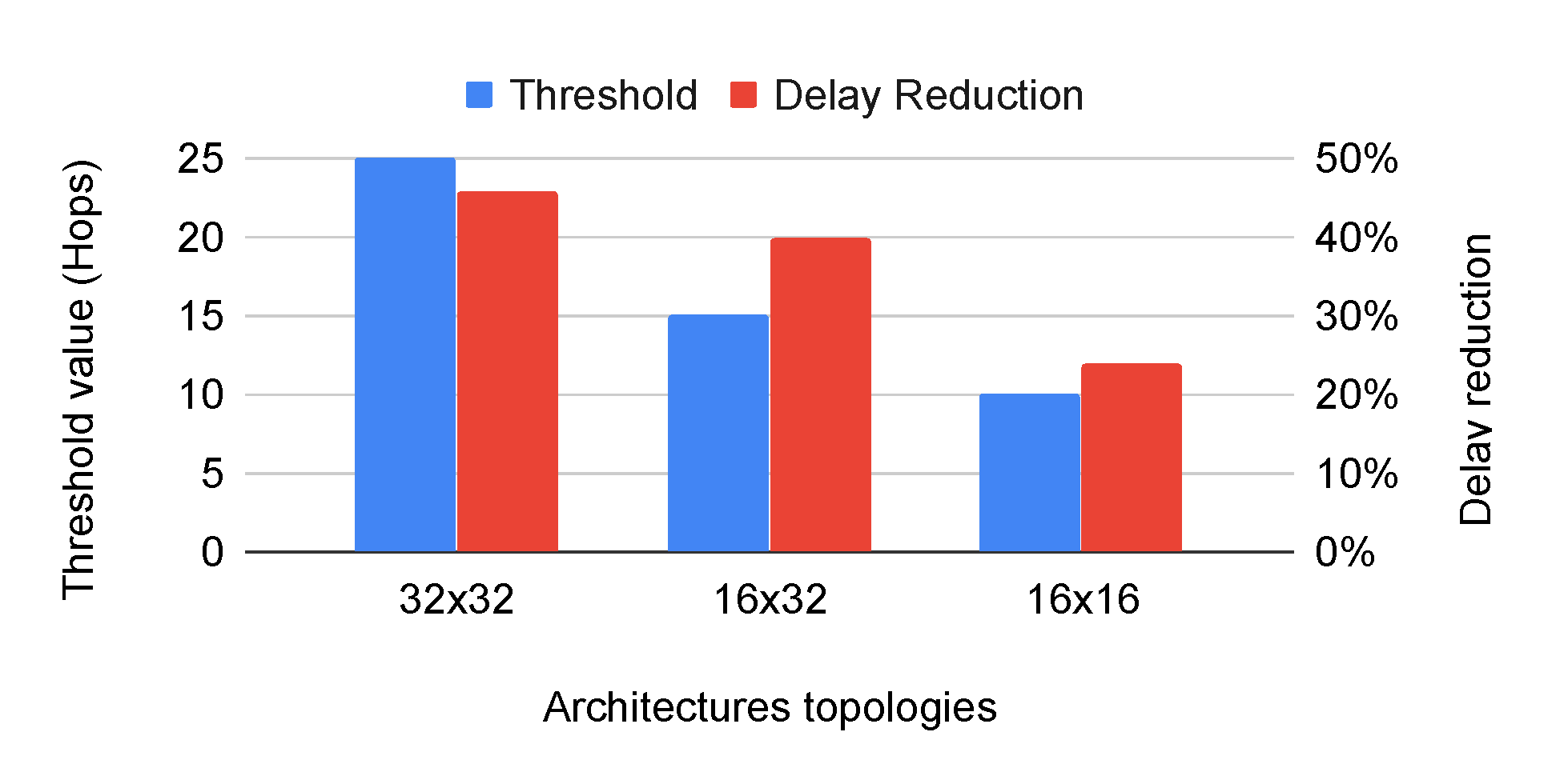
Figure 9 shows the threshold value evolution and the maximum reached delay reduction. We notice that the threshold value and the delay reduction increases along with the network size for the considered application. From
Figure 9 we can conclude that for Splash2-FFT, in a
topology, and 25 hops as threshold form the best combination leading for the highest network latency reduction, as illustrated in
Figure 8b showing the importance of the threshold selection.
6.3. Results Comparison
After presenting the results obtained with the synthetic traffic and the results provided by the proposed framework, we compare these two outcomes. For this, we consider the example of the Splash2-FFT application for the
NoC architecture. The first step is the characterization of the application reported in
Table 4 in order to identify the closest scenario and PIR value. Then, we compare these values with results reported in
Figure 7a,d. The considered application has 75% of long-range communications and the nearest PIR value is
. Note that there is a small difference between the total number of communications inside the RF-NoC between the synthetic traffic and the real one (17,560 communications) that has to be taken into account, that’s why we pass to the PIR value of
. The suitable threshold value is 25 hops, which is proved by the proposed framework in
Figure 8a. For delay reduction, we reach almost the same percentage (about 50%) compared to the conventional NoC. If we apply the same steps for
and
topologies, we found almost the same threshold value, but there is a difference in the percentage of the delay reduction. The synthetic traffic reports a higher percentage of latency reduction in
Figure 7e,f compared to results obtained from the use of the framework in
Figure 9 which is due to the difference in the total number of communications that is not negligible in these topologies.
6.4. Simulation Time
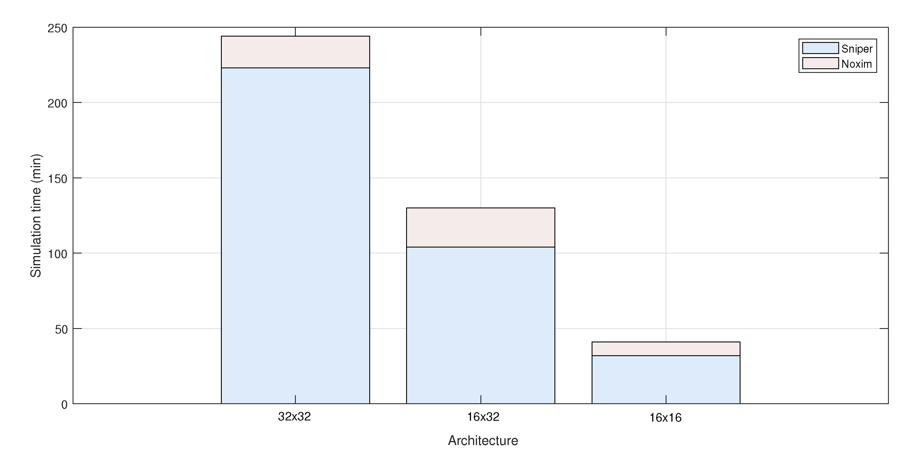
An important feature of a design exploration framework is the simulation time.
Figure 10 represents the simulation times when simulating Splash2-FFT benchmark for the 3 considered topologies i.e., 32 × 32, 16 × 32 and 16 × 16 using the framework. All simulations were done on a DELL Latitude 5580 computer, with Intel core i7 processor, 16 Gb RAM, running ubuntu 16.04 LTS. The simulation time of Sniper depends on the benchmark, whereas the simulation time of Noxim depends on the number of clock cycles we want to simulate. In this example, we set the simulation time to 10k clock cycles in Noxim. That is, actual communication flows simulated by Sniper are replaced with statistical communication flows in Noxim. According to
Figure 10, we observe that the simulation times increase along with the benchmark complexity. Thus, the fraction of simulation time of Sniper dominates the total simulation time. Even if we change Noxim’s input parameters (threshold value, RF bandwidth, modulation order, etc.) the results may remain roughly the same.

 ,
, 


