Article

Metal Additive Manufacturing Cycle in Aerospace Industry: A Comprehensive Review

1
Department of Mechanical Engineering, Centre for Mechanical Technology & Automation, University of Aveiro, 3810-193 Aveiro, Portugal
2
Active Space Technologies, Actividades Aeroespaciais S.A., Parque Industrial de Taveiro, Lote12, 3045-508 Coimbra, Portugal
*
Author to whom correspondence should be addressed.
J. Manuf. Mater. Process. 2019, 3(3), 52; https://0-doi-org.brum.beds.ac.uk/10.3390/jmmp3030052
Submission received: 29 May 2019 / Revised: 13 June 2019 / Accepted: 21 June 2019 / Published: 26 June 2019
(This article belongs to the Special Issue Recent Development in Metal Additive Manufacturing)

Abstract

:
Additive Manufacturing (AM) is the forefront of advanced manufacturing technologies and has the potential to revolutionize manufacturing, with a dramatic change in the design and project paradigms. A comprehensive review of existent metal AM processes, processable materials, respective defects and inspection methods (destructive and non-destructive) is presented in a succinct manner. Particularly, the AM design optimization methodologies are reviewed and their threats and constraints discussed. Finally, an aerospace industry case study is presented and several cost-effective examples are enumerated.

1. Introduction

Metal-based Additive Manufacturing (AM) is a rapidly growing industry, exceeding $1030M in 2016 with a $7150M revenue being forecasted by 2026 [1]. For instance, titanium additive manufactured parts are expected to reach a revenue of $350M in 2020 and $1030M in 2024 [2]. From an economic perceptive, paradigms are changing from mass production to mass customization and personalization due to technological developments [3,4,5]. Advanced manufacturing technologies are important promoters of this change of paradigm, which are likely to improve productivity. Moreover, the drastic increase of flexibility allows some industries to offer personalization options and reduce the overall time to market [3].
Additive Manufacturing, in particular Selective Laser Melting (SLM) and Electron Beam Melting (EBM), is at the forefront of the advanced manufacturing technologies [6]. Recently, important AM patents (e.g., [7,8,9,10,11,12]) have expired. Therefore, new companies in the field are emerging and the competition is increasing. Nowadays, the list of AM processes is long and many alternative processes are emerging on the market [13]. Metal-based AM processes consist in the manufacturing of a 3D object layer by layer, providing great design freedom. However, how to fully explore this freedom should be further developed, with the AM engineering cycle rethought [14].
Current design optimization tools do not allow to take full advantage of AM capabilities and several threats are still present. These particularities need to be accounted for in the design optimization, process simulation and structural verification stages [14]. Figure 1 shows a typical AM engineering cycle, where the symbiotic and iterative nature between the stages is also represented.
Despite all challenges and threats present in AM engineering cycles, its ability to produce lightweight structures has already been explored by the industry. For instance, the launch fees of the NEOSAT satellite costs a few tens of thousands of Euros per kilogram (An unofficial communication of P.B. Selding (Space News editor) on Twitter puts the cost at 31,000 Dollars per kilogram) and, thus, the ability to reduce weight or increase functionality becomes attractive for the aerospace industry. Nickels [15] analyzed the possible impact of AM in the referred industry, and reported several advantageous applications. For example, the development time frame of a structural bracket was reduced from six months to one using the AM technology [15], and the relation between AM and aerospace seems promising.
The goal of the present paper is to critically review AM engineering cycles in their threats, development tools and constraints in order to assess its current stage and identify its needs. The first part reviews the existing metal AM processes and, for the sake of clarity, divide them by category, referring their key characteristics and materials that can be processed. Typical defects are also listed, as well as their origin and respective inspection methods. Additionally, this article provides the reader with an overview of the processes’ physics (following the authors of [16,17]) to improve the reader’s understanding of typical defects and limitations. The second part of the work reviews the current design approaches, regarding their capabilities and limitations. Moreover, the currently available computational design tools are listed and the main limitations, from the manufacturing point of view, are reviewed. The third and final part reports to some of the European Space Agency (ESA) research interests and, cost-effective examples from aerospace industry are listed.

2. Additive Manufacturing

2.1. Processes Review

Metal-based Additive Manufacturing (AM) is a general concept and several technologies could be referred, including some technologies with a limited presence on the market, such as cold spray or sheet lamination. Cold spray refers to the deposition of powder material onto a substrate using pressurized gas (70 bar@1100 °C). The particles collide with the cold part forming a solid-state metallurgical bond. It is, therefore, best suited for the addition of near-net-shape features onto components, such as bosses, lugs onto shafts or coating application [18,19,20,21,22]. Another technology is sheet lamination, where each layer is represented by a sheet/foil. These are bonded together until a 3D shape is reached. For example, Fabrisonic commercializes machines that use this technology and bonds the foils together using ultrasonic welding. Moreover, this technology is already integrated into a hybrid solution [19]. Recently, a patent was published, where the bonding is performed using diffusion or friction welding [23].
Within the scope of this work, processes with higher relevance on the market are reviewed, being grouped in two main categories: Powder Bed Fusion (PBF) and Direct Energy Deposition (DED) [24]. In the PBF processes, layers of powder are applied and a heat source (laser or electron beam) selectively melts the applied powder. Then, the baseplate moves downwards and a new layer of powder is applied. In DED processes, the addition of material (powder or wire) is directly fed into the melt pool. Figure 2a,b shows the basic working principles involved and Table 1 compares their main characteristics.

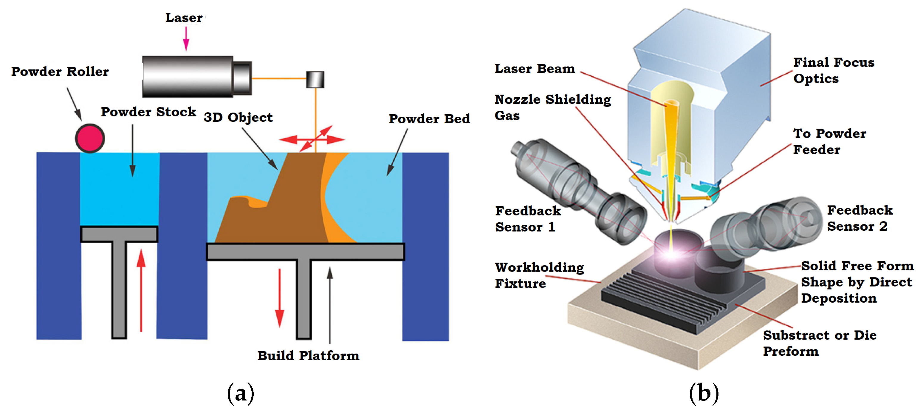
2.1.1. Powder Bead Fusion

The PBF processes takes advantage of a focused energy source that selectively melts or sinters a layer of powder. Different processes are available, as summarized in Table 2. The main energy sources are the laser and the electron beam for Selective Laser Sintering/Melting (SLS or SLM) and Electron Beam Melting (EBM) processes, respectively. The EBM consists on high powered Scanning Electron Microscope (SEM), while SLS/SLM consists of a set of lens, mirror and galvanometer to positioning the laser beam [27].
EBM processes selectively melt the powder in vacuum conditions. The addition of a low-pressure helium atmosphere is used due to the risk of electrostatic discharges of the powder. This vacuum condition is almost a perfect protection against corrosion.
Currently, Ti-6Al-4V alloys are widely used in the aerospace industry due to their mechanical properties and fatigue strength [2,28]. Other possible materials are nickel-based alloys, which have excellent mechanical properties and resistance to creep and corrosion. However, these alloys are difficult to process and some are not weldable. The EBM process allows melting the metal above 1100 °C and, at these temperatures, these alloys can be successfully processed. Due to their creep resistance, these are used in high-temperature applications such as in aero-engines or power plants (e.g., inconel 625 or inconel 718 alloys). Cobalt-based alloys (e.g., vitalinum or stellite), cooper alloys, steel and stainless steel are possible materials to be processed by EBM [27]. This process does not require stress relief since the residual stresses are minimal. After the process, Hot Isostatic Pressing (HIP) is optional, since there are claims that it is possible to reach fully dense body (>99.9%) in as-built condition (without thermal post-processing) [27].
SLM process selectively melts the powder in an inert atmosphere (i.e., argon). Additionally, a few SLM machines are capable of providing pre-heating, either to the substrate plate or the entire building chamber. The most used powder with this technology is steel and other iron-based alloys (32%) [29]. Other powders are titanium and its alloys, Ni-based alloys and other metals such as aluminum, copper, magnesium, cobalt-chrome, tungsten, and gold (decreasing order of relevance) [29]. This process leads to high residual stress, with stress relief treatment being mandatory and HIP recommended. Due to the residual stress, cracking defects were identified [30]. However, thermal gradients in this process generate fine grain structures, which results in better strength limits than its cast counterparts with lower malleability [29]. However, during thermal treatment, the increased grain size has been reported [28], which leads to a decrease of strength and increase of material’s malleability.
SLS process allows building parts without thermally affecting the metallic powder, since the powder contains polymeric binders, which are melted by a laser. This allows the construction of parts with great complexity and envelope. However, the process requires a furnace treatment in order to vaporize the polymeric binder and sinter the particles. At elevated temperature (below melting), the diffusion between particles occurs in order to minimize the free energy. If sufficient thermal input is provided, the densification of powder occurs, decreasing porosity with the cost of the volume shrinkage. The archived density (around 50%) is still not acceptable. Thus, an infiltration with other material or HIP process is required. This process can use different powders and, as infiltrating material, bronze or Cu-P/Ni alloys are used [31,32].
The direct metal SLS or Direct Metal Laser Sintering (DMLS) uses a mixture of low- and high-temperature melting point powders. Therefore, the laser scan is tuned to melt the powder with a lower melting point. The process requires longer times frames (and, consequently, lower building speed) when compared with SLS [33]. However, these parts can be used without furnace treatment, but in this cases strength is limited. Commercial solutions such as EOS-DMLS steel 50-V1 (contains steel, Cu-P and Ni) produce components with a relative density of 70% that can be used as inserts and small mold components [31].

2.1.2. Direct Energy Deposition

DED processes apply energy into a narrow, focused region in order to melt the substrate and simultaneously add melting material into the substrate’s melting pool. Contrasting with PBF processes, DED processes melt material as it is being deposited. The material can be either powder or wire, its energy source being a laser, an electron beam or plasma (Table 3) [32].
Regarding laser-based systems, several companies have been developing DED machines. These assume different names depending on the company, such as Laser Engineered Net Shaping (LENS), Directed Light Fabrication (DLF), Direct Metal Deposition (DMD), 3D Laser Cladding, Laser Generation, Laser-Based Metal Deposition (LBMD), Laser Freeform Fabrication (LFF), Laser Direct Casting, LaserCast, Laser Consolidation, LasForm and others [32]. These lasers processes are capable of processing materials such as titanium alloys (i.e., Ti-22Al-23Nb and Ti-48-2-2, TiC), steels (i.e., 10 V, 15-5 PH, 410, 416, AISI 309, Aermet 100, A2, MM 10, and CPM S7), nickel-based super alloys (i.e., CMSX-3, Haynes 188, Haynes 230, IN600, IN690, IN713, MarM247, Rene 142, and Rene N5), aluminium alloys (i.e., Al 6061 and Al 2024) and copper alloys (i.e., Cu-10%Sn and GRCop-84). In all of these cases, a controlled atmosphere is necessary (i.e., Argon), being obtained with an inert gas chamber (i.e., LENS) or by the use of shielding gas flow (i.e., 3D Laser Cladding) [34]. These technologies produce near shape parts that need to be post treated and allows great control over the resultant microstructures. Nevertheless, residual stress builds up and a stress relief is required and HIP is recommended.
Regarding DED electron beam-based systems, Electron Beam Freeform Fabrication (EBF3) was developed by NASA Langley to produce or repair parts, both terrestrially and in future space-based systems. The system uses wire as the source material instead of powder since the handling of powder in zero gravity would represent a major challenge. These electron beam DED machines are built in massive vacuum chambers. Similar to EBM, EBF3 produces ready to use parts in as-built condition. The final residual stresses are low and almost fully dense bodies are obtained. DED processes are limited in terms of geometrical freedom [32]. Regarding processable materials, these technologies can process titanium and its alloys, Inconel (IN718, IN625), tantalum, tungsten, niobium, stainless steel (300), aluminum (2319 and 4043), AISI 4340 steel, Zircalloy, and 70–30 copper–nickel and 70–30 nickel–copper alloys [35].
Regarding plasma-based systems, these are simply a gas metal arc welding machine combined with multiple axis platforms or robotic arms (e.g., Ramlab [36]), with low cost and reasonable build up speeds. However, poor control over the heat affected areas, microstructures or defects, have been the main drawbacks that have kept these approaches from wide spreading [32]. This technology requires stress relief and furnace treatments in order to improve microstructural properties and reduce defects [37].

2.1.3. Hybrid Manufacturing

The CNC technology provides advantages such as repeatability, precision and productivity with good surface finish, although being wasteful and geometrically limited, as well as having difficulty processing certain materials. On the other hand, AM technologies provide less material waste, more geometrical freedom and high buy-to-fly ratio, but it has long time cycles and poor surface finishing. To take advantage of both worlds, the technologies were combined into a single technology called Hybrid Manufacturing (HM) [38,39,40,41,42].
Companies such as Mastsura (Japan) and Sodick (UK) combine PBF with CNC while companies such as DMG Mori (USA), Mazzak (Japan), Reichenbacher Hamuel (Germany), and WFL (Germany) combine DED technologies with CNC. The most suitable application of these technologies is to build add-ons on existent parts or repair them. This avoids the build of a primary substructure to support the build and its post-processing, representing major gains in costs. Some of these machines can have the laser re-purposed for laser graving or cutting [43,44].
Recently, a company called Hybrid Manufacturing Technologies provides retrofitting solutions to common CNC machines with no major changes on the machine. For instance, the protective atmosphere is provided through the nozzle in the form of shielding gas flow. The solution is a compact design that includes the systems for the thermal source (laser), powder supply and protective gas supply. Furthermore, this company also provides these solutions to other companies to integrate on their new machines (partner alliances) [43,44].

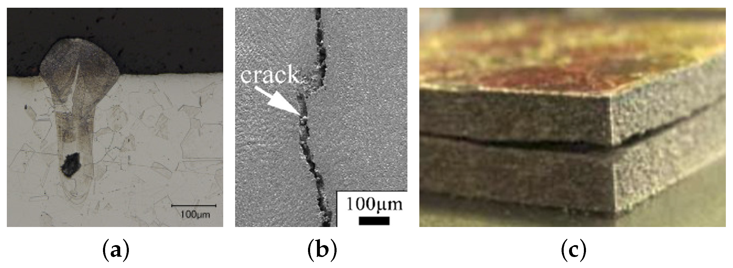
2.2. Origin of Defects and Its Inspection Methods

The deposited material is melted and the shape of the melted pool is a relevant parameter. As is its solidification process. During the solidification, the first step is the nucleation. In most AM parts, the nucleation of a new phase is not required due to the presence of the previous layers, since the regrow can occur from the existent material. However, if two dissimilar materials were used, the nucleation of new phase might be required and, consequently, an energy barrier must be overcome. This affects the final microstructure and may result in poor or non-existent inter-metallic bound. Thus, a progressive transition between the dissimilar materials is recommended.
To obtain good quality parts, there must be some remelting of the previous layer in order to remove contaminants and break oxides. Thus, a clean solid–liquid interface is provided, serving as a growth interface for the solidification process. The temperature gradient (G), the solidification rate (R) and the undercooling ( Δ T) are the key parameters of the solidification process. In the presence of high ratios of G/R, the solidified microstructures tend to be planar. However, as ratio decreases, the microstructures tend to be cellular or columnar dendritic or equiaxed dendritic, as shown in Figure 3 [16].
In the PBF process, the fast laser scanning forms severe thermal gradients that lead planar microstructures, forming very elongated grains with a high length/depth ratio. Moreover, the grain growth direction follows the thermal gradient and, therefore, the build direction. This grain alignment with the build direction can lead to unwanted anisotropy effects present in some additively manufactured parts. However, in a DED process, the grain growth direction does not necessarily follow the build direction and has a similar length and depth. The process tends to form columnar dendritic structures due to the shape and size of the melted pool. After an AM part cools down below solidus temperature, it still needs to reach room temperature and several phase transformations can occur [16].
Any industry is cost driven and, therefore, reducing the build time of AM parts or reducing costs in feedstock materials, is wanted. However, increasing speed or decreasing quality of feedstock material increase the defects. The first cause for poor quality of AM parts is the powder quality in its shape, size distribution, surface morphology, composition and flowability (Figure 4a,b provides an example). For instance, poor flowability leads uneven layer deposition (PBF) or inconstant flow of powder (DED), which often leads to non-conform metal parts. Another source for failed parts is the incorrect reusing powder policies, where the same powder is used several times.
Therefore, the quality of AM raw material needs monitoring and to establish minimal quality standards in the morphology, flowability, particle size and distribution, chemical composition and allowable variation, reusing powder policies, and criteria for defect acceptance, further testing is needed [48]. Scanning Electron Microscopy (SEM) and/or X-Ray Computed Tomography (CT) can be used to monitor powder quality [16,49].
During an AM process, parameters can be maximized up to a certain limit. For instance, increasing the build speed eventually leads to instability of molten pool originating elongated pools, which break in isolated bubbles of isolated liquid (This defect is commonly called humping.). Thus, a compromise between speed and quality is often required. During metal melting, the temperature reaches elevated values. Therefore, vaporization of alloys elements can occur, since these elements are more volatile than others. However, the increase in temperature does not necessarily imply high vaporization rates. The higher temperature facilitates the vaporization. However, the size of the molten pool is also increased, increasing the stability of the pool. Combined with vaporization issues, there is the elements’ segregation, where alloy elements migrate from the bulk material to grain boundaries. Therefore, the lack of micro-structural homogeneity is another defect that needs quantification. Some non-destructive methods of measurement chemical composition are X-Ray Energy Dispersive Spectroscopy (EDS) or Electron Probe MicroAnalysis (EPMA). Inductively Coupled (ICP) mass spectrometry presents a higher accuracy, but it is a destructive method [16,28].
To increase the competitiveness of the AM process, machines may operate at very high power densities and deposition rates. Sometimes the temperature of the molten pool reaches the boiling point of the alloy and a vapor cavity is formed, which improves the laser absorption. This operating mode is called the keyhole mode. Without its careful control, it can lead to defects since the keyhole mode may become unstable, leaving voids (keyhole induced porosity, as depicted in Figure 5a) due to gas entrapment.
Another origin of porosity is the gas entrapment in the powder (during its production, leading to microporosity), or in lack of powder fusion (low laser absorption due to powder shape and/or morphology). There are several techniques to measure porosity such as Optical Microscopy (OM), Electron Microscopy (EM), X-Ray Computer Tomography (X-Ray CT) and Synchrotron Radiation Micro-Tomography (SR μ T) [16,50,51,52,53,54,55].
Excessive surface roughness is a common defect that is unacceptable and needs expensive post-processing. The first reason for this defect is the “stair step effect”. If the layer thickness is increased, the roughness is increased, and, therefore, a compromise needs to be reached. The second reason is related to process parameters. Humping effect or poor melting of powder are causes for large surface roughness, which can be measured using profilometer or analyzing the surface morphology using SEM (see Figure 4c) [16,56,57,58].
Cracking and delamination are other defects. The solidification will eventually suffer contraction and distortion due to thermal and inelastic strains (viscoplasticity, and creep and phase transformations). However, the previous layers already suffered the contraction process and, therefore, there is a differential contraction between layers that causes the stresses to build up. If these reach the strength limit, cracking occurs along grain boundaries (see Figure 5b) or between layers (delamination, as depicted in Figure 5c). The element segregation allows the formation of carbides between grains. The stiffness difference between the carbides and the grains leads to stress concentrations within micro-structure that become the primary cracking site during cyclic loading. Another direct consequence of stress building up is distortion, being one of the main reasons for non-admissible final parts [16]. Thus, residual stress is a key point that needs quantification. There are techniques to measure residual stress, such as Vickers micro-indentation (indirect measure), hole drilling combined laser holography and/or strain gauges, X-ray and neutron diffraction techniques [16,59,60].
Table 4 summarizes the main possible defects of AM metal parts and possible tests to identify and quantify them [16,61,62].
To deal with referred unwanted effects, some post treatments are usually performed. To reduce residual stress and/or reduce porosity, stress relief and/or HIP processes are performed. However, the treatments are not standard and may produce unwanted effects if not properly defined such as excessive distortion or loss of mechanical properties. Apart from thermal treatments, there is the surface quality treatment that involves machining (e.g., interfaces) and/or polishing. There are numerous types of polishing, namely: mechanical, chemical, electromechanical, vibrational or blasting. In the case of internal surfaces (difficult access), the polishing is accomplished using chemical or electrochemical or abrasive flows (suspensions of SiC, Al 2 O 3 , diamond, and WC particles) [63]. Finally, the quality inspections with the acceptance criteria and their standardization are needed. In fact, the certification process of AM parts in the aerospace industry is an on-going task. The European Aviation Safety Agency (EASA) and the Federal Aviation Administration (FAA) have established committees with the purpose of regulating and standardizing these new technologies [64].

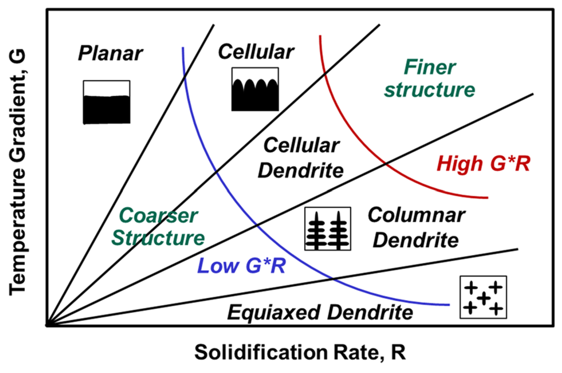
2.3. AM Material Behavior

In the aerospace industry, the most used metals are titanium and aluminum alloys, stainless steel and nickel alloys. Titanium alloys, especially Ti-6Al-4V, is known for its impressive ratio of strength/mass, however, a trade-off between ductility and strength is required. On the one hand, the as-built parts tend to have higher strength but lower ductility. On the other hand, the heat-treated parts can provide more ductility at a strength cost. In some cases, these alloys show similar strength in the transverse and longitudinal directions, while, in other cases, a deviation of 7% was found, depending on the process parameters [16,65]. Furthermore, the size of the component (characteristic length) appears to be another variable. For instance, a component 1.7 mm in length showed 20% more strength and 80% less ductility when compared with a 7-mm part. The presence of large pores close to the surface was found to have a higher impact on the fatigue performance of these alloys [16,17].
AM aluminum parts are mainly produced with AlSi10Mg alloys. Their high content of silicon promotes low melting ranges, high hot tearing resistance and low shrinkage during solidification, without introducing brittleness and reducing void generation (porosity). In general, the resulting mechanical properties are better or equal to those obtained in casting processes due to the obtained fine microstructures [66], with no notable anisotropy being present [16]. However, high cycle fatigue of AlSi10Mg AM parts still requires unreasonably high factors of safety, being highly susceptible to local defects [67]. Regarding Al6061 alloys, these are widely used by industry (aerospace included) due to their weldability, corrosion resistance and suitability for critical safety applications. However, the low silicon content presence results in unacceptable levels of cracking, anisotropy and porosity, making Al6061 alloy unattractive for AM applications [66].
Austenitic stainless-steel AM parts, in as-built condition, exhibit higher strength, hardness, and anisotropy as well as lower ductility when compared with their traditionally processed counterparts. This is attributed to refined microstructure (due to rapid solidification), its structure (dendritic and cellular), higher dislocation density and residual stress (around 60–90% of yield strength). The fatigue performance of AM parts (PBF-L AISI316L) is negatively affected by the surface roughness. However, roughness reduction using machining increased the strength limit by 25% (from 200 to 250 MPa) [16].
Ni-based alloys obtained from AM require a trade-off between strength and ductility, having considerable levels of anisotropy [16,68]. Lack of fusion defects was reported to have a relevant impact in the fatigue life of AM parts in as-built condition (DED-SLM IN718), reducing its life by a factor of 2/3. On the contrary, these alloys when heat treated have shown fatigue life similar to their conventionally casted or wrought counterparts (DED-SLM IN718) [69,70] and higher creep resistance. This increase in resistance is attributed to a higher density of precipitates in their microstructure. Other Ni-based alloys, e.g., Haynes 230 (PBF-SLM), have also shown meaningful improvement of mechanical properties (yield and tensile strength) when compared to cast and wrought material. However, ductility is negatively affected due to the evident element segregation on the microstructure (cellular and dendritic structures) [71]. In short, metal-based AM parts show as good or even better mechanical properties when compared with a conventional cast or wrought parts [72].

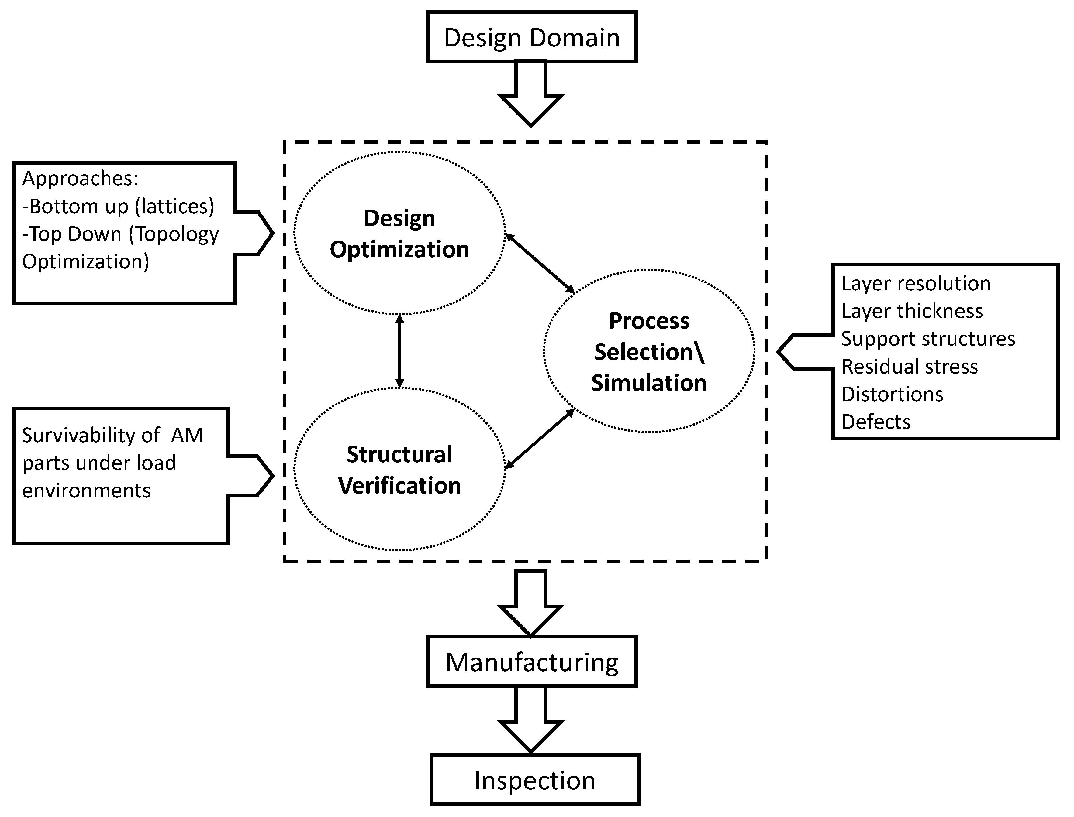
3. AM Design Optimization

AM has the potential to reduce mass since the complexity of the part can be raised without drastically raising its cost. The AM engineering cycle requires several steps, namely design optimization, manufacturing and inspection. Recently, Walton and Moztarzadeh [73] presented a classic case study, where the design optimization cycle was performed using Topology Optimization (TO), compliance minimization was the goal and mass and stress were the constraints. Moreover, a member size limitation of 6 mm (min.) and 12 mm (max.) was used. Figure 6a presents the design domain as well as the boundary conditions, while Figure 6b represents the density maps of TO, considering a threshold of 0.25. Taking into consideration the results of TO, the part was redesigned and manufactured.
Figure 6c depicts the AM part in its as-built condition, where the considerable amount of support structures is visible. Figure 6d depicts the AM part post-treated and Figure 6e depicts its X-Ray inspection, where an inclusion defect was found. Despite the relevant advantages of AM technologies, the reliability of the part still faces many challenges [4,74] and their success is still dependent on the minimization of certain threats and limitations.

3.1. Threats

Current design approaches are changing to take full advantage of AM technology. Particularly, to make AM economically viable, highly optimized designs are needed, representing a challenging task. Currently, three mains approaches can be indicated: bottom-up, top-down and mixed.
  • The bottom-up approach is based on unit cells (lattices) that are uniformly repeated in every direction. The apparent simplicity of this approach is betrayed by its uncertainties on its analysis and the CPU cost.
  • The top-down approach is based on topological optimization for both continuum and discrete domains. Nonetheless, TO provides great opportunities due to its ability to produce lightweight structures. However, this methodology sometimes produces “unfriendly” AM structures (e.g., overhangs), associated to high computational costs of optimization and analysis. Moreover, the output of these methodologies is density maps that need to be translated into geometrical forms, requiring another non-trivial step [14].
  • A mixed approach can be defined, being a combination of the previous ones. Instead of a uniform distribution of the unit cells, a multiscale algorithm can be used, where the densities from the topology optimization define the level of robustness of the unit cell (e.g., diameter of truss bars) [75,76,77]. However, the translation of the referred densities into a final 3D model raises several computational challenges.
Current design tools (sketch based) are optimized for conventional technology (e.g., the “add hole” typical command). Thus, the edition of 3D shape using current software is complex and requires extensive training, being difficult to use and disseminate. Bottom-up approaches have some integrated software to guide the user from the beginning to the end of the design process. Software packages such as Netfabb (Autodesk), Creo 4.0 (PTC), Meshup (Uformia), and Magics (Materialise) are examples. In the same way, top-down approaches use software that combines topological optimization methods with design tools. Moreover, there are many general propose topological optimization solvers, which are summarized in Table 5 due to their extensive list.
The structural verification of AM parts and the prediction of its failure mechanisms raise serious challenges with high-level uncertainty due to defects, anisotropy and residual stress. Moreover, other parameters (such as the surface finishing) affect the part performance. To anticipate possible issues, some companies created software for the building process simulation (also generates the necessary support structures). Thus, it is allegedly possible to predict residual stress and distortions on a part and compensate distortions on the design in order to improve final dimensional accuracy. The higher is the accuracy the less overbuild is necessary, therefore improving its economic competitiveness. Netfabb Simulation (Autodesk—former Pan computing), Simufact (MSC), Amphyon (Additive Works—Partner Alliance with Altair), Virfac (Geonx) and ExaSIM (Ansys) are examples of software packages specialized in building simulation of AM process. An alternative software solution could be FAME (Swerea), which has a general public license, but numerous limitations. In general, these software packages use multiple scales combined with other techniques in order to reduce computation time. In fact, if the simulation takes longer than the process, it will have little use.

3.2. Design Limitations

AM processes have limitations in their build time and allowable dimensions. Moreover, the cycle time of these technologies is significantly higher when compared with conventional technologies. However, this drawback can be suppressed by the opportunity of reducing material waste, increasing functionally, highly geometrical customization or reducing the difficulty to process materials (i.e., inconel or titanium). From the scalability point of view, the AM processes are limited by their nature, since the layer resolution is limited to a specific range (0.2–2.5 mm) and the scalability is also limited. On the other side, small layer thickness is also wanted, since it improves surface finish. Thus, this compromise is a recurrent problem in AM processes [14]. Additionally, its repeatability is questionable, since two identical parts on the same machine may or may not produce parts with the same structural robustness [48].
Design optimization shall be performed taking into consideration the manufacturing process and its constraints. The main constraints are the member size, cavity and support structures constraints:
  • Member size constraints improve manufacturability and reduce post-processing operations, being an important and fundamental constraint.
  • Cavity constraints intend to avoid enclosed voids of powder (PBF process), which can be difficult to remove in a later stage. However, cavities do not necessarily appear and their industrial relevance is limited. When they appear, their structural benefits should overcome the work of introducing a hole in the design in order to vacuum the unmelted powder.
  • Overhang constraints intend to minimize (or ideally eliminate) the appearance of overhanging structures and, therefore, the need for support structures (cost reduction). Thus, it is a relevant topic and represents a strong design restriction [79].
The optimization of the build direction can (sometimes) reduce the need for support structures. The study in Ref. [80] proposes a method for searching the optimal build orientation which minimizes their use. The study in Ref. [81] proposes a TO methodology that brings the AM overhang constraints into the TO methodology, where a maximum angle of 45 degrees is considered in order to avoid support structures.
Figure 7a,b illustrates the TO results (for 2D only) without and with overhang constraints, respectively. However, this gain in eliminating support structures comes with a stiffness cost, increasing its compliance by 16%.
For instance, a study in Ref. [82] proposes another method of introducing overhang constraints into the TO methodology, resulting in a different design philosophy. Figure 7d,e presents the TO results (for 2D only) without and with overhang constraints, respectively. Recently, a study in Ref. [83] suggests another method for introducing overhang constraints into the TO methodology for the 3D domain. Other studies (e.g., [84,85,86]) have also addressed this issue.
The application of the previous methodologies to reduce the number of support structures is pertinent since costs are reduced. However, such heavy restrictions might steer the solution away from the optimal solution. In addition, support structures might be necessary, even if the structure is self-supporting, r to prevent excessive distortion and/or cracking. In addition, excessive distortion can lead to recoater interference and, therefore, a failed build. If the top-down approach produces hollow structures, internal support structures might be required, which can be challenging to remove in a later stage. Finally, it is necessary to have exit points for the non-melted powder extraction [81,87]. In a bottom-up approach, the internal support structures can be avoided, with a careful selection of the unit cell and the print direction. However, the extraction of the unmelted powder and the smoothing of surfaces becomes a challenge. In short, a compromise between cost and performance is generally made.

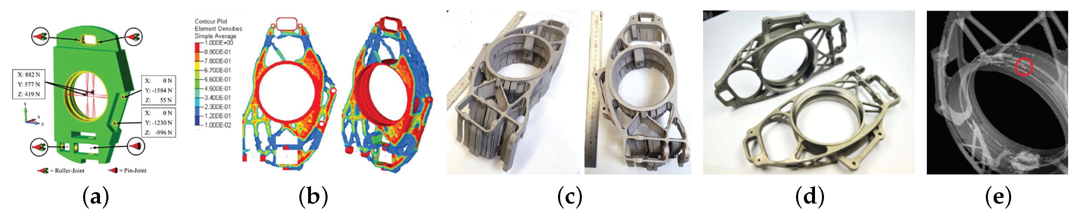
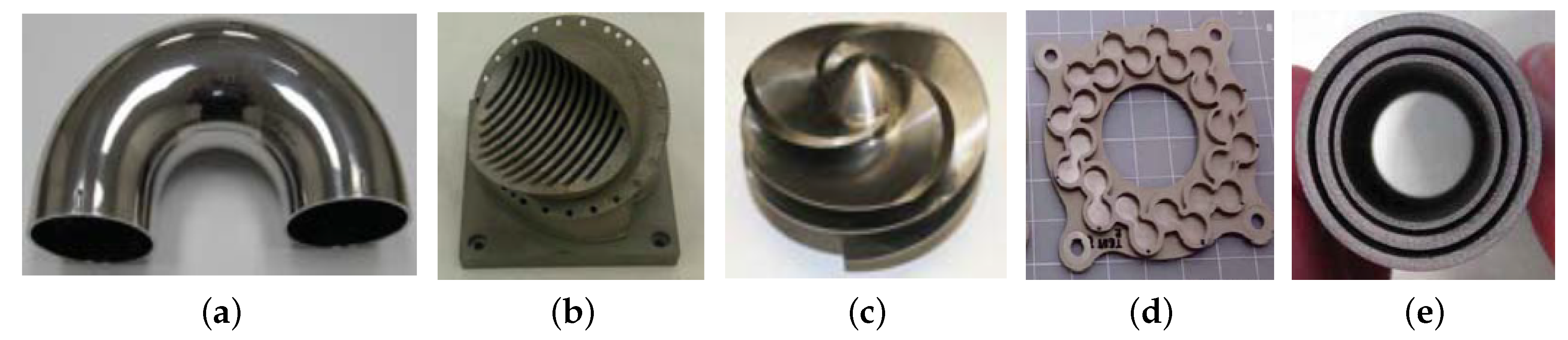
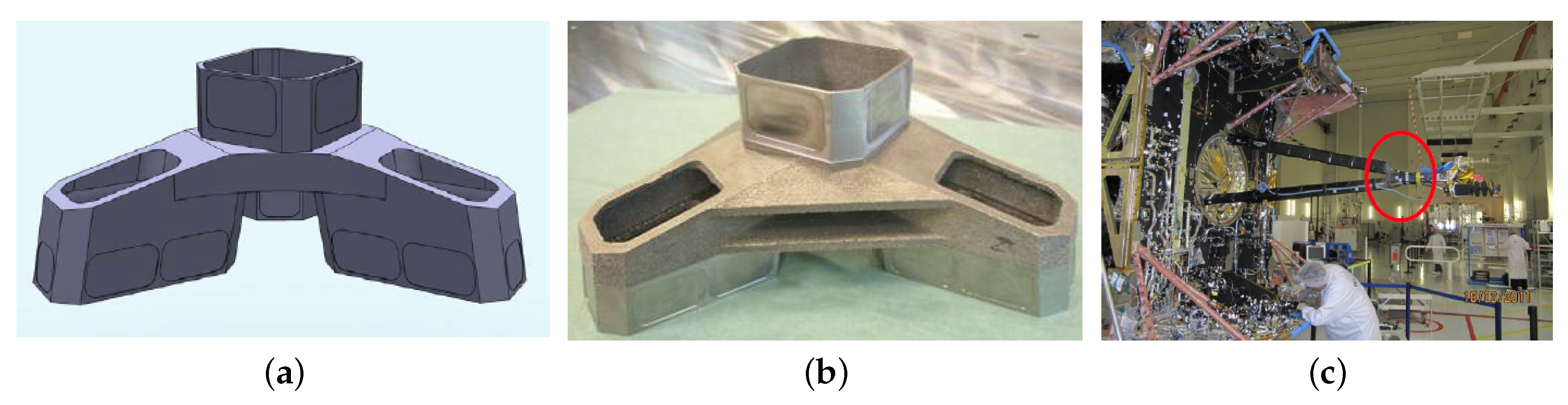
4. Case Studies From Aerospace Industry

The metal AM in the Aerospace Industry will succeed if it enables overall cost, lead-time and risk reduction. For instance, this can be achieved by reducing the number of parts, joints (welds are causes for long term failures) and/or increasing the added value of the final part (increased functionality per part). Moreover, these technologies still need efforts towards its qualification and standardization [61,88,89]. Recently, the European Space Agency (ESA) has opened calls to explore these opportunities. For instance, the development of embedded thermal functions in structural parts using 3D printing, or the development of one single part integrating waveguide filter, bends, coupler and supporting structures by AM, projects that could be financed by ESA within the ITT (Invitation To Tender) (e.g., [90,91]). The material behavior and its structural response limit the widespread use of metal-based AM since they still represent challenges [92]. One of the recent projects from ESA consists in the development of supply chains, capable of producing high-end parts made of titanium, aluminum, Inconel and Invar. The mechanical characterization and post-processing (blasting, stress relief and HIP) are also included [93]. Another project consists in the development and characterization of new high strength aluminum alloys including their mechanical performance and common defects [94].
The current main space applications of metal AM is limited to a few applications. The first main application is rocket propulsion, namely components such as injectors, gas generator duct, pogo z-baffle, turbo pump inducer, flex joint, monolithic thrusters, chambers and nozzles [95,96]. Figure 8a–c illustrates a J-2X Gas Generator Duct, a Pogo Z-Baffle and a Turbopump Inducer, respectively. Gains of 70% in costs and 50% in time were reported for the Duct. In the Pogo part, gains of 64% in costs and 75% in time were disclosed. Regarding the inducer, 50% cost and 80% time reductions were declared, where the comparison term for these gains was their conventional manufacturing [96].
Others applications are auxiliary structures such as thermoelastic mounts (Optic instruments need extremely stable structures, i.e., a thermal strain can misalign lenses or focal distances), wave guides filters, heat switches, structural components with embedded thermal functions (heat pipes) and components with tailored properties. On suborbital sounding rocket mission, there is a battery case (FY13), which was successfully built by AM [96], as shown in Figure 8d. For instance, an instrument prototype of thermal heat switch based on concentric titanium tubes was built by AM. The complexity of this component comes from the small gaps between tubes and the difficulties and price of processing titanium [96], as shown in Figure 8e.
On the Atlantic Bird mission (ESA 2011), a structural bracket made of titanium was built by AM (EBM) with a TRL (Technology Readiness Level) of 9 (flight model), having a mass reduction of 30% [97] (Figure 9a,c).
According to T. Ghidini [95], another AM structural bracket was designed and successfully validated, where 46% mass reduction was achieved. Figure 10a,d describes the old design and the new AM design, respectively. Moreover, the number of interfaces was reduced, maintaining the structural robustness.
A supplementary space application of an AM bracket is given by Figure 10b,e, depicting their conventional and AM designs, respectively. Reductions of 25% in cost and 50% in weight were projected [98,99,100]. The antenna bracket of sentinel I weighs 1.626 kg and, thus, a potential for improvements was identified. From a partnership between RUAG and EOS, a new bracket was redesigned for AM. The final design margins of static loads, strength and stiffness were positive and a 26% mass reduction was obtained [99,100]. Figure 10c,f depicts the conventional and AM designs, respectively.

5. Conclusions

The AM market is rapidly growing and many AM machines suppliers are already available. Sometimes, the mechanical properties of the resultant parts show better properties than the brought counterparts, but its repeatability is still a challenge as is its standardization. Either raw material or process-induced, micro-structural defects are the cause for the questionable repeatability and their identification can be performed with different methods.
The AM engineering cycle has to be rethought to reach its full potential. Its stages (Design Optimization and Process Simulation) have many tools already available, but it still lacks the proper unification and maturity. Moreover, the integration of manufacturing constraints in the design methodologies is still in its infancy, although some methodologies have already been published already. Regarding the strength analysis stage, this represents a major challenge due to a number of phenomena such as anisotropy, porosity and residual stress.
In the aerospace industry, a number of cost-effective examples are available, where cost and weight reductions were verified. Project calls are being opened to finance its further development (i.e., ESA Projects), since its potential is widely accepted. Nonetheless, their field of application is restricted to complex parts (weight, materials and/or shape).

Author Contributions

Conceptualization, B.B., A.A.-C., R.A.F.V. and V.N.; methodology, B.B., A.A.-C., R.A.F.V. and V.N.; validation and formal analysis, B.B., A.A.-C., R.A.F.V. and V.N.; investigation, B.B.; writing—original draft preparation, B.B.; writing—review and editing, B.B., A.A.-C., R.A.F.V. and V.N.; project administration, A.A.-C.; funding acquisition, A.A.-C. and R.A.F.V.

Funding

This research was funded by the Portuguese Foundation for Science and Technology (FCT) under the projects CENTRO-01-0145-FEDER-029713 by UE/FEDER through the programs CENTRO 2020 and COMPETE 2020, and UID/EMS/ 00481/2013-FCT under CENTRO-01-0145-FEDER-022083. Additional funding was provided by program CENTRO 2020 and UE/FEDER through the project CENTRO-01-0247-FEDER-024039, designated as ADVANSS. Finally, the Portuguese Foundation for Science and Technology (FCT) provided additional funding via the scholarship SFRH/BD/120779/2016.

Acknowledgments

The authors gratefully acknowledge the financial support of the Portuguese Foundation for Science and Technology (FCT), program CENTRO 2020 and UE/FEDER.

Conflicts of Interest

The authors declare no conflict of interest.

References

  1. Hertenberger, S. (Ed.) Market Report ID: 44670015/Global. Available online: www.maschinenmarkt.international/english/global/articles/604851/ (accessed on 18 November 2017).
  2. Dutta, B.; Froes, F.H. Additive Manufacturing of Titanium Alloys; Butterworth-Heinemann: Oxford, UK, 2016. [Google Scholar]
  3. Tao, F.; Cheng, Y.; Zhang, L.; Nee, A.Y.C. Advanced manufacturing systems: Socialization characteristics and trends. J. Intell. Manuf. 2017, 28, 1079–1094. [Google Scholar] [CrossRef]
  4. Ustundag, A.; Cevikcan, E. Industry 4.0: Managing The Digital Transformation; Springer International Publishing: Cham, Switzerland, 2018. [Google Scholar]
  5. Bremen, S.; Meiners, W.; Diatlov, A. Selective Laser Melting: A manufacturing technology for the future? Laser Tech. J. 2012, 9, 33–38. [Google Scholar] [CrossRef]
  6. Murr, L.E.; Gaytan, S.M.; Ramirez, D.A.; Martinez, E.; Hernandez, J.; Amato, K.N.; Shindo, P.W.; Medina, F.R.; Wicker, R.B. Metal Fabrication by Additive Manufacturing Using Laser and Electron Beam Melting Technologies. J. Mater. Sci. Technol. 2012, 28, 1–14. [Google Scholar] [CrossRef]
  7. Wikening, C.; Lohner, A. Aparatus for Producing a Three-Dimensional Object. U.S. Patent 5753274, 19 May 1998. [Google Scholar]
  8. Russell, D.B.; Anderson, T.; Bredt, J.F.; Vogel, M.J.; Seymor, M.; Bornhorst, W.J.; Hatsopoulus, M.I. Aparatus for Producing a Three-Dimensional Object. U.S. Patent 6007318, 19 May 1999. [Google Scholar]
  9. Batchelder, J.S.; Crump, S.S. Method for Rapid Prototyping of Solid Models. U.S. Patent 5866058, 2 February 1999. [Google Scholar]
  10. Manning, G.L. End-of-Vector Laser Power Control in a Selective Laser Sintering System. U.S. Patent 08866600, 4 July 1997. [Google Scholar]
  11. Meiners, W.; Wissenbach, K.; Gasser, A. Selective Laser Sintering at Melting Temperature. U.S. Patent 09319132, 10 April 1997. [Google Scholar]
  12. Swanson, W.J.; Hopkins, P.E. Thin-Wall Tube Liquifier. U.S. Patent 09013388, 21 December 1998. [Google Scholar]
  13. Hornick, J.; Bhushan, A. More 3D Printing Patents Are Expiring Soon: Here’s a Roundup. Available online: 3dprintingindustry.com (accessed on 12 October 2018).
  14. Gao, W.; Zhang, Y.; Ramanujan, D.; Ramani, K.; Chen, Y.; Williams, C.B.; Wang, C.C.; Shin, Y.C.; Zhang, S.; Zavattieri, P.D. The status, challenges, and future of additive manufacturing in engineering. Comput. Aided Des. 2015, 69, 65–89. [Google Scholar] [CrossRef]
  15. Nickels, L. AM and aerospace: An ideal combination. Met. Powder Rep. 2015, 70, 300–303. [Google Scholar] [CrossRef]
  16. DebRoy, T.; Wei, H.L.; Zuback, J.S.; Mukherjee, T.; Elmer, J.W.; Milewski, J.O.; Beese, A.M.; Wilson-Heid, A.; De, A.; Zhang, W. Additive manufacturing of metallic components—Process, structure and properties. Prog. Mater. Sci. 2018, 92, 112–224. [Google Scholar] [CrossRef]
  17. Gorsse, S.; Hutchinson, C.; Goune, M.; Banerjee, R. Additive manufacturing of metals: A brief review of the characteristic microstructures and properties of steels, Ti-6Al-4V and high-entropy alloys. Sci. Technol. Adv. Mater. 2017, 18, 584–610. [Google Scholar] [CrossRef] [PubMed]
  18. Machine Supplier Website. Available online: http://www.twi-global.com (accessed on 26 October 2017).
  19. Machine Supplier Website. Available online: http://www.hermle-generativ-fertigen.de (accessed on 26 October 2017).
  20. Sun, W.; Tan, A.W.; Bhowmik, A.; Marinescu, J.; Huong, Y.; Liu, E. Additive manufacturing of inconel 625 superalloy parts via high pressure cold spray. In Proceedings of the 3rd International Conference on Progress in Additive Manufacturing, Nanyang Technological University, Singapore, 14–17 May 2018. [Google Scholar]
  21. Pathak, S.; Saha, G.C. Development of Sustainable Cold Spray Coatings and 3D Additive Manufacturing Components for Repair/Manufacturing Applications: A Critical Review. Coatings 2017, 7, 122. [Google Scholar] [CrossRef]
  22. Wang, X.; Feng, F.; Klecka, M.A.; Mordasky, M.D.; Garofano, J.K.; El-Wardany, T.; Nardi, A.; Champagne, V.K. Characterization and modeling of the bonding process in cold spray additive manufacturing. Addit. Manuf. 2015, 8, 149–162. [Google Scholar] [CrossRef]
  23. Wu, L. Method and System for Additive Manufacturing of Complex Metal Part by Sheet Lamination. U.S. Patent 0207924 A1, 26 July 2018. [Google Scholar]
  24. Tofail, S.A.; Koumoulos, E.P.; Bandyopadhyay, A.; Bose, S.; O’Donoghue, L.; Charitidis, C. Additive manufacturing: Scientific and technological challenges, market uptake and opportunities. Mater. Today 2018, 21, 22–37. [Google Scholar] [CrossRef]
  25. Machine Supplier Website. Available online: http://www.3dprintingkorea.co.kr/default.asp (accessed on 17 December 2018).
  26. Dutta, B.; Froes, F.S. The Additive Manufacturing (AM) of titanium alloys. Met. Powder Rep. 2017, 72, 96–106. [Google Scholar] [CrossRef]
  27. Körner, C. Additive manufacturing of metallic components by selective electron beam melting—A review. Int. Mater. Rev. 2016, 61, 361–377. [Google Scholar] [CrossRef]
  28. Sames, W.J.; List, F.A.; Pannala, S.; Dehoff, R.R.; Babu, S.S. The metallurgy and processing science of metal additive manufacturing. Int. Mater. Rev. 2016, 61, 315–360. [Google Scholar] [CrossRef]
  29. Yap, C.Y.; Chua, C.K.; Dong, Z.L.; Liu, Z.H.; Zhang, D.Q.; Loh, L.E.; Sing, S.L. Review of selective laser melting: Materials and applications. Appl. Phys. Rev. 2015, 2, 041101. [Google Scholar] [CrossRef]
  30. Zhang, B.; Li, Y.; Bai, Q. Defect Formation Mechanisms in Selective Laser Melting: A Review. Chin. J. Mech. Eng. 2017, 30, 515–527. [Google Scholar] [CrossRef] [Green Version]
  31. Kruth, J.; Wang, X.; Laoui, T.; Froyen, L. Lasers and materials in selective laser sintering. Assem. Autom. 2003, 23, 357–371. [Google Scholar] [CrossRef]
  32. Gibson, I.; Rosen, D.; Stucker, B. Additive Manufacturing Technologies; Springer: New York, NY, USA, 2015; pp. 107–145. [Google Scholar]
  33. Bunnell, D.E.; Das, S.; Bourell, D.L.; Beaman, J.B.; Marcus, H.L. Fundamentals of Liquid Phase Sintering During Selective Laser Sintering. Assem. Autom. 2003, 24, 440–447. [Google Scholar]
  34. Shamsaei, N.; Yadollahi, A.; Bian, L.; Thompson, S.M. An overview of Direct Laser Deposition for additive manufacturing; Part II: Mechanical behavior, process parameter optimization and control. Addit. Manuf. 2015, 8, 12–35. [Google Scholar] [CrossRef]
  35. Machine Supplier Website. Available online: http://www.sciaky.com (accessed on 26 October 2017).
  36. Service Supplier Website. Available online: http://www.ramlab.com (accessed on 26 October 2017).
  37. Szost, B.A.; Terzi, S.; Martina, F.; Boisselier, D.; Prytuliak, A.; Pirling, T.; Hofmann, M.; Jarvis, D.J. A comparative study of additive manufacturing techniques: Residual stress and microstructural analysis of CLAD and WAAM printed Ti–6Al–4V components. Mater. Des. 2016, 89, 559–567. [Google Scholar] [CrossRef]
  38. Flynn, J.M.; Shokrani, A.; Newman, S.T.; Dhokia, V. Hybrid additive and subtractive machine tools—Research and industrial developments. Int. J. Mach. Tools Manuf. 2016, 101, 79–101. [Google Scholar] [CrossRef]
  39. Du, W.; Bai, Q.; Zhang, B. A Novel Method for Additive/Subtractive Hybrid Manufacturing of Metallic Parts. Procedia Manuf. 2016, 5, 1018–1030. [Google Scholar] [CrossRef] [Green Version]
  40. Manogharan, G.; Wysk, R.A.; Harrysson, O.L. Additive Manufacturing—Integrated Hybrid Manufacturing and Subtractive Processes: Economic Model and Analysis. Int. J. Comput. Integr. Manuf. 2015, 29, 473–488. [Google Scholar] [CrossRef]
  41. Yamazaki, T. Development of A Hybrid Multi-tasking Machine Tool: Integration of Additive Manufacturing Technology with CNC Machining. Procedia CIRP 2016, 42, 81–86. [Google Scholar] [CrossRef]
  42. Merklein, M.; Junker, D.; Schaub, A.; Neubauer, F. Hybrid Additive Manufacturing Technologies—An Analysis Regarding Potentials and Applications. Phys. Procedia 2016, 83, 549–559. [Google Scholar] [CrossRef]
  43. Machine Supplier Website. Available online: http://www.hybridmanutech.com/ (accessed on 26 October 2017).
  44. Jones, J.B. Hybrid CNC + Additive: Two Heads Are Better Than One; Wohlers Talk: SME’s RAPID; Wohlers: Long Beach, CA, USA, 2015. [Google Scholar]
  45. Lee, Y.; Nordin, M.; Babu, S.S.; Farson, D.F. Effect of Fluid Convection on Dendrite Arm Spacing in Laser Deposition. Metall. Mater. Trans. B 2014, 45, 1520–1529. [Google Scholar] [CrossRef]
  46. Li, R.; Shi, Y.; Wang, Z.; Wang, L.; Liu, J.; Jiang, W. Densification behavior of gas and water atomized 316L stainless steel powder during selective laser melting. Appl. Surf. Sci. 2010, 256, 4350–4356. [Google Scholar] [CrossRef]
  47. Gu, D.; Shen, Y. Balling phenomena in direct laser sintering of stainless steel powder: Metallurgical mechanisms and control methods. Mater. Des. 2009, 30, 2903–2910. [Google Scholar] [CrossRef]
  48. Addispace. Diagonosis and Study of Oportunities of Metallic Additive Manufacturing on SUDOE Aerospatial Sector; Technical Report for Sudoe and Interreg: Santander, Spain, December 2016. [Google Scholar]
  49. Hadadzadeh, A.; Baxter, C.; Amirkhiz, B.S.; Mohammadi, M. Strengthening mechanisms in direct metal laser sintered AlSi10Mg: Comparison between virgin and recycled powders. Addit. Manuf. 2018, 23, 108–120. [Google Scholar] [CrossRef]
  50. Du Plessis, A.; le Roux, S.G. Standardized X-ray tomography testing of additively manufactured parts: A round robin test. Addit. Manuf. 2018, 24, 125–136. [Google Scholar] [CrossRef]
  51. Townsend, A.; Racasan, R.; Leach, R.; Senin, N.; Thompson, A.; Ramsey, A.; Bate, D.; Woolliams, P.; Brown, S.; Blunt, L. An interlaboratory comparison of X-ray computed tomography measurement for texture and dimensional characterisation of additively manufactured parts. Addit. Manuf. 2018, 23, 422–432. [Google Scholar] [CrossRef]
  52. Wits, W.W.; Carmignato, S.; Zanini, F.; Vaneker, T.H. Porosity testing methods for the quality assessment of selective laser melted parts. CIRP Ann. 2016, 65, 201–204. [Google Scholar] [CrossRef]
  53. Fieres, J.; Schumann, P.; Reinhart, C. Predicting failure in additively manufactured parts using X-ray computed tomography and simulation. Procedia Eng. 2018, 213, 69–78. [Google Scholar] [CrossRef]
  54. Gong, H.; Rafi, K.; Gu, H.; Starr, T.; Stucker, B. Analysis of defect generation in Ti–6Al–4V parts made using powder bed fusion additive manufacturing processes. Addit. Manuf. 2014, 1–4, 87–98. [Google Scholar] [CrossRef]
  55. Aboulkhair, N.T.; Everitt, N.M.; Ashcroft, I.; Tuck, C. Reducing porosity in AlSi10Mg parts processed by selective laser melting. Addit. Manuf. 2014, 1–4, 77–86. [Google Scholar] [CrossRef]
  56. Chen, Z.; Wu, X.; Tomus, D.; Davies, C.H. Surface roughness of Selective Laser Melted Ti-6Al-4V alloy components. Addit. Manuf. 2018, 21, 91–103. [Google Scholar] [CrossRef]
  57. Tian, Y.; Tomus, D.; Rometsch, P.; Wu, X. Influences of processing parameters on surface roughness of Hastelloy X produced by selective laser melting. Addit. Manuf. 2017, 13, 103–112. [Google Scholar] [CrossRef]
  58. Safdar, A.; He, H.; Wei, L.; Snis, A.; de Paz, L.E.C. Effect of process parameters settings and thickness on surface roughness of EBM produced Ti-6Al-4V. Rapid Prototyp. J. 2012, 18, 401–408. [Google Scholar] [CrossRef]
  59. Robinson, J.; Ashton, I.; Fox, P.; Jones, E.; Sutcliffe, C. Determination of the effect of scan strategy on residual stress in laser powder bed fusion additive manufacturing. Addit. Manuf. 2018, 23, 13–24. [Google Scholar] [CrossRef]
  60. Salmi, A.; Atzeni, E.; Iuliano, L.; Galati, M. Experimental Analysis of Residual Stresses on AlSi10Mg Parts Produced by Means of Selective Laser Melting (SLM). Procedia CIRP 2017, 62, 458–463. [Google Scholar] [CrossRef]
  61. Seifi, M.; Gorelik, M.; Waller, J.; Hrabe, N.; Shamsaei, N.; Daniewicz, S.; Lewandowski, J.J. Progress Towards Metal Additive Manufacturing Standardization to Support Qualification and Certification. JOM 2017, 69, 439–455. [Google Scholar] [CrossRef]
  62. Teng, C.; Pal, D.; Gong, H.; Zeng, K.; Briggs, K.; Patil, N.; Stucker, B. A review of defect modeling in laser material processing. Addit. Manuf. 2017, 14, 137–147. [Google Scholar] [CrossRef]
  63. Choi, H.; Byun, J.M.; Lee, W.; Bang, S.R.; Kim, Y.D. Research Trend of Additive Manufacturing Technology— A = B + C + D + E, add Innovative Concept to Current Additive Manufacturing Technology: Four Conceptual Factors for Building Additive Manufacturing Technology. J. Korean Powder Metall. Inst. 2016, 23, 149–169. [Google Scholar] [CrossRef]
  64. Joshi, S.C.; Sheikh, A.A. 3D printing in aerospace and its long-term sustainability. Virtual Phys. Prototyp. 2015, 10, 175–185. [Google Scholar] [CrossRef]
  65. Baufeld, B.; Brandl, E.; van der Biest, O. Wire based additive layer manufacturing: Comparison of microstructure and mechanical properties of Ti–6Al–4V components fabricated by laser-beam deposition and shaped metal deposition. J. Mater. Process. Technol. 2011, 211, 1146–1158. [Google Scholar] [CrossRef]
  66. Roberts, C.E.; Bourell, D.; Watt, T.; Cohen, J. A Novel Processing Approach for Additive Manufacturing of Commercial Aluminum Alloys. Phys. Procedia 2016, 83, 909–917. [Google Scholar] [CrossRef] [Green Version]
  67. Romano, S.; Bruckner-Foit, A.; Brandao, A.; Gumpinger, J.; Ghidini, T.; Beretta, S. Fatigue properties of AlSi10Mg obtained by additive manufacturing: Defect-based modelling and prediction of fatigue strength. Eng. Fract. Mech. 2018, 187, 165–189. [Google Scholar] [CrossRef]
  68. Kelly, S.M. Volume 1: Development and Measurement Analysis of Design Data for Laser Powder Bed Fusion Additive Manufacturing of Nickel Alloy 625; Deliverable under Cooperative Agreement No. 70NANB12H26. EWI Technical Report; National Institute of Standards and Technology, United States Department of Commerce: Gaithersburg, MD, USA, 2014.
  69. Johnson, A.S.; Shuai, S.; Shamsaei, N.; Thompson, S.M.; Bian, L. Fatigue behaviour and failure mechanisms of direct laser deposited inconel 718. In Proceedings of the Solid Freeform Fabrication Symposium—An Additive Manufacturing Conference: University of Texas in Austin, Austin, TX, USA, 8–10 August 2016; pp. 499–511. [Google Scholar]
  70. Amsterdam, E.; Kool, G.A. High Cycle Fatigue of Laser Beam Deposited Ti-6Al-4V and Inconel 718. In ICAF 2009, Bridging the Gap between Theory and Operational Practice; Springer: Dordrecht, The Netherlands, 2009; pp. 1261–1274. [Google Scholar]
  71. Bauer, T.; Dawson, K.; Spierings, A.B.; Wegener, K. Microstructure and Mechanical Characterisation of SLM Processed Haynes ® 230 ®; Technical Report; Laboratory for Freeform Fabrication, University of Texas: Austin, TX, USA, 2011. [Google Scholar]
  72. Murr, L. Metallurgy of additive manufacturing: Examples from electron beam melting. Addit. Manuf. 2015, 5, 40–53. [Google Scholar] [CrossRef]
  73. Walton, D.; Moztarzadeh, H. Design and Development of an Additive Manufactured Component by Topology Optimisation. Procedia CIRP 2017, 60, 205–210. [Google Scholar] [CrossRef]
  74. Uriondo, A.; Esperon-Miguez, M.; Perinpanayagam, S. The present and future of additive manufacturing in the aerospace sector: A review of important aspects. Proc. Inst. Mech. Eng. Part G J. Aerosp. Eng. 2015, 229, 2132–2147. [Google Scholar] [CrossRef]
  75. Liu, C.; Du, Z.; Zhang, W.; Zhu, Y.; Guo, X. Additive Manufacturing-Oriented Design of Graded Lattice Structures Through Explicit Topology Optimization. J. Appl. Mech. 2017, 84, 081008. [Google Scholar] [CrossRef]
  76. Brackett, D.; Ashcroft, I.; Hague, R. Topology Optimization for Additive Manufacturing. Available online: https://sffsymposium.engr.utexas.edu/Manuscripts/2011/2011-27-Brackett.pdf (accessed on 25 June 2019).
  77. Maskery, I.; Aboulkhair, N.; Aremu, A.; Tuck, C.; Ashcroft, I.; Wildman, R.; Hague, R. A mechanical property evaluation of graded density Al-Si10-Mg lattice structures manufactured by selective laser melting. Mater. Sci. Eng. A 2016, 670, 264–274. [Google Scholar] [CrossRef] [Green Version]
  78. Ferguson, I.; Frecker, M.; Simpson, T.W.; Dickman, C.J. Topology Optimization Software for Additive Manufacturing: A Review of Current Capabilities and a Real-World Example. In Volume 2A: 42nd Design Automation Conference; ASME: Charlotte, NC, USA, 2016. [Google Scholar]
  79. Clausen, A. Topology Optimization for Additive Manufacturing. Ph.D. Thesis, DTU Mechanical Engineering, Technical University of Denmark, Lyngby, Denmark, 2016. [Google Scholar]
  80. Das, P.; Chandran, R.; Samant, R.; Anand, S. Optimum Part Build Orientation in Additive Manufacturing for Minimizing Part Errors and Support Structures. Procedia Manuf. 2015, 1, 343–354. [Google Scholar] [CrossRef] [Green Version]
  81. Gaynor, A.T.; Guest, J.K. Topology optimization considering overhang constraints: Eliminating sacrificial support material in additive manufacturing through design. Struct. Multidiscip. Optim. 2016, 54, 1157–1172. [Google Scholar] [CrossRef]
  82. Guo, X.; Zhou, J.; Zhang, W.; Du, Z.; Liu, C.; Liu, Y. Self-supporting structure design in additive manufacturing through explicit topology optimization. Comput. Methods Appl. Mech. Eng. 2017, 323, 27–63. [Google Scholar] [CrossRef] [Green Version]
  83. Zhao, D.; Li, M.; Liu, Y. Self-supporting Topology Optimization for Additive Manufacturing. CoRR 2017, arXiv:1708.07364. [Google Scholar]
  84. Allaire, G.; Dapogny, C.; Estevez, R.; Faure, A.; Michailidis, G. Structural optimization under overhang constraints imposed by additive manufacturing technologies. J. Comput. Phys. 2017, 351, 295–328. [Google Scholar] [CrossRef] [Green Version]
  85. Mirzendehdel, A.M.; Suresh, K. Support structure constrained topology optimization for additive manufacturing. Comput. Aided Des. 2016, 81, 1–13. [Google Scholar] [CrossRef] [Green Version]
  86. Langelaar, M. Topology optimization of 3D self-supporting structures for additive manufacturing. Addit. Manuf. 2016, 12, 60–70. [Google Scholar] [CrossRef] [Green Version]
  87. Gaynor, A.T. Topology Optimization Algorithms for Additive Manufacturing. Ph.D. Thesis, The Johns Hopkins University, Baltimore, MD, USA, 2015. [Google Scholar]
  88. Frazier, W.E. Metal Additive Manufacturing: A Review. J. Mater. Eng. Perform. 2014, 23, 1917–1928. [Google Scholar] [CrossRef]
  89. Seifi, M.; Salem, A.; Beuth, J.; Harrysson, O.; Lewandowski, J.J. Overview of Materials Qualification Needs for Metal Additive Manufacturing. JOM 2016, 68, 747–764. [Google Scholar] [CrossRef] [Green Version]
  90. ESA Open Invitation to Tender AO9085. Development of Embedded Thermal Functions in Structural Parts Using 3D Printing. Available online: http://www2.rosa.ro/index.php/en/esa/oferte-furnizori/2318-development-of-embedded-thermal-functions-in-structural-parts-using-3d-printing (accessed on 25 June 2019).
  91. ESA Open Invitation to Tender AO9112. Development of One Single Part Integrating Waveguide Filter, Bends, Coupler, Supporting Structures by Additive Manufacturing. Available online: http://www2.rosa.ro/index.php/en/esa/oferte-furnizori/2378-development-of-one-single-part-integrating-waveguide-filter-bends-coupler-supporting-structures-by-additive-manufacturing (accessed on 25 June 2019).
  92. Energetics Incorporated. Measurement Science Roadmap for Metal-Based Additive Manufacturing: Workshop Summary Report; Technical Report; NIST: Maryland, DC, USA, 2013.
  93. ESA Open Invitation to Tender AO9094. Advanced Aluminium Alloys Tailored for Additive Manufacturing Space Applications, Targeting High End Structural Spacecraft Parts. Available online: http://www2.rosa.ro/index.php/en/esa/oferte-furnizori/2359-advanced-aluminum-alloys-tailored-for-additive-manufacturing-space-applications-targeting-high-end-structural-spacecraft-parts (accessed on 25 June 2019).
  94. ESA Open Invitation to Tender AO 9032. Additive Manufacturing Powder Material Supply Chain: Verification and Validation. Available online: http://www2.rosa.ro/index.php/en/esa/oferte-furnizori/2337-additive-manufacturing-powder-material-supply-chain-verification-and-validation (accessed on 25 June 2019).
  95. Ghidini, T. An Overview of Current AM Activities at the European Space Agency: 3D Printing Additive Manufacturing—Industrial Applications; 3D Printing & Additive Manufacturing; Industrial Applications Global Summit: London, UK, 2013. [Google Scholar]
  96. Werkheiser, N. Overview of NASA Initiatives in 3D Printing and Additive Manufacturing; DoD Maintenance Symposium: Birmingham, UK, 2014. [Google Scholar]
  97. Ghidini, T. European Space Agency Perspective on Additive Manufacturing (AM): 3D Printing Additive Manufacturing—Industrial Applications; 3D Printing & Additive Manufacturing; Industrial Applications Global Summit: London, UK, 2013. [Google Scholar]
  98. Oerlikon. RUAG Deepens Cooperation With Oerlikon to Achieve Serial Production of 3D Printed Components for Space. Available online: additivemanufacturing.com (accessed on 12 October 2018).
  99. Bromberger, M. Technology Symbiosis Additive Manufacturing & Topology Optimization. In Additive Manufacturing Design & Engineering Symposium; Altair Engineering, Inc.: Troy, MI, USA, 2014. [Google Scholar]
  100. Aerospace: RUAG—Additive Manufacturing of Satellite Components. Available online: www.eos.info (accessed on 11 October 2018).
Figure 1. Overview of AM engineering cycle.
Jmmp 03 00052 g001
Figure 2. General working principle of PBF and DED categories [25,26].
Jmmp 03 00052 g002
Figure 3. Effect of R and G in the solidification process [45].
Jmmp 03 00052 g003
Figure 4. SEM images showing characteristic morphologies of powders produced: (a) using gas atomization; and (b) water atomization [46]. (c) SEM image depicts solid powders on build surface [47].
Jmmp 03 00052 g004
Figure 5. AM defects: (a) keyhole induced porosity; (b) cracks; and (c) delamination [16].
Jmmp 03 00052 g005
Figure 6. Engineering cycle of an AM part: (a) presentation of the design domain and boundary conditions; (b) density maps of TO, considering the threshold at 0.25; (c) AM part still with the support structures; (d) machined AM part; and (e) its X-Ray inspection [73].
Jmmp 03 00052 g006
Figure 7. Comparison of TO results (a) without and (b) with overhang constraints using a simplified fabrication model [81]. TO results (d) without and (e) with overhang constraints using moving morphable components [82]. TO results (c) without and (f) with overhang constraints using convolution methodology [83].
Jmmp 03 00052 g007
Figure 8. Cost-effective examples of additive manufactured parts: (a) a J-2X Gas Generator Duct; (b) a Pogo Z-Baffle; (c) a Turbopump Inducer; (d) a battery case; and (e) heat switch prototype [96].
Jmmp 03 00052 g008
Figure 9. Flight AM part [97]: (a) the CAD model; (b) the manufactured part; and (c) its location the satellite.
Jmmp 03 00052 g009
Figure 10. AM optimized structural brackets [95,98]: (a,d), (b,e) and (c,f) examples of optimized brackets from their conventional design to their AM design.
Jmmp 03 00052 g010
Table 1. General comparison of PBF and DED processes.
CriteriaPowder Bed Fusion (PBF)Direct Energy Deposition (DED )
Build speed [cm 3 /h]up to 170up to 2000
Max. build size ( X ; Y ; Z ) [mm](0.8; 0.4; 0.5)(4.0; 2.0; 1.0)
Accuracy0.05/250.25/25
Min. thickness [mm]0.21.0
Surface quality [ μ m]Ra 10Ra 20
Design FreedomHighLow
ApplicationsRapid prototypingRepairing parts
High end partsAdding features (i.e., ribs and lugs)
The values presented on this table are merely references and were based on manufacturers information and press research. Depending on the part, process and material, these values can change.
Table 2. PBF process comparison.
TechnologyAdvantagesDisadvantagesMachines Companies
Shared specsCost effectivePowder exit pointsArcan (Sweden)
Geometrical complexityQuality powder dependentEOS (Germany)
High resolutionPowder quantityConcept laser Cusing (Germany)
EBMMinimal residual stressBuild rateMTT (Germany)
No thermal treatmentsPowder varietyPhoenix System Group (France)
Mechanical strengthVacuum atmosphereRenishaw (UK)
MalleabilitySurface finishRealizer (Germany)
Cost3D Systems (USA)
SLMMechanical strengthBuild rateMatsuura (Japan)
Surface finishResidual stressTrumf (Germany)
Stress relief/HIPVoxeljet (Germany)
MalleabilityExOne (USA)
Inert atmosphere
SLSBuild ratePolymeric binder
Foot printThermal treatments
Mechanical strength
DMLSBuild rateMechanical strength
Low density
EBM, Electron Beam Melting; SLM, Selective Laser Melting; SLS, Selective Laser Sintering; DMLS, Direct Metal Laser Sintering.
Table 3. DED process comparison.
TechnologyAdvantagesDisadvantagesMachines Companies
LENS/DLF/DMDBuild rateSurface finishOptomec (USA)
LBDM/LFFFoot printGeometrical complexityInssTek (USA)
Microstructure controlResolutionIrepa Laser (France)
Mechanical strengthControlled atmosphereTrumpf (Germany)
Repair toolMetal varietySciaky (USA)
Coating toolResidual stressBeAM (USA)
Stress relief/HIP
EBAMHigh build rateSurface finish
Foot printGeometrical complexity
Microstructure controlPoor resolution
Mechanical strengthVacuum atmosphere
Residual stressMetal variety
No thermal treatments
PlasmaVery high build rateMicrostructure controlRamlab (Netherlands)
CostGeometrical complexity
Resolution
Thermal treatments
Accuracy
Surface finish
LENS, Laser Engineered Net Shaping; DLF, Direct Light Fabrication; DMD, Direct Metal Deposition; LBMD, Laser Based Metal Deposition; LFF, Laser Free Form Fabrication.
Table 4. AM common defects and its inspection methods [16,61,62].
DefectProcess PBF/DEDDescriptionInspection Methods
Vaporization of Alloy ElementsBothLoss of alloy elements due to vaporization compromises mechanical strengthX-Ray EDS (NDI)
EPMA (NDI)
ICP mass spectrometry (DI)
Porosity and voidsBothQuality Powder: Hollow powder (gas entrapment)X-Ray CT (NDI)
Process instabilities (keyhole voids, lack of penetration, …)SEM (NDI)
Surface RoughnessBoth“Stair step effect”, humping effect and powder poor meltingProfilometer (NDI)
SEM (NDI)
CrackingBothUneven contraction of deposited material builds up stress until strength limit originating fractureVickers micro-indentation (Indirect measure and DI)
Hole drilling combined laser holography and/or strain gauges (DI)
X-Ray and Neutron diffraction (NDI)
DelaminationPBF ECT (NDI)
DistortionBothResidual stress leads to strains → Out of toleranceConventional Metrology (NDI)
Trapped PowderPBFHollow Structures needs powder extraction pointsCT ( NDI)
RT (NDI)
NDI, Non-Destructive Inspection; DI, Destructive Inspection; EDS, Energy Dispersive Spectroscopy; EPMA, Electron Probe MicroAnalysis; ICP, Inductively Coupled; CT, Computed Tomography; SEM, Scanning Electron Microscopy; ECT, Edge Current Testing; RT, Resonance Testing.
Table 5. Overview of Topology Optimization (TO) software: commercial and educational [78]. Its developer, Finite Element Analysis (FEA) solver, analysis regimes (S—Static; E—Eigenvalues; and D—Dynamic Loading) and the existence of post-processing tools (smoothing and export) are also presented.
Commercial SoftwareDeveloperFEA SolverAnalysis RegimeSmoothing/Export
DreamcatcherAutodeskStandaloneS,EYes/Yes
Within EnhanceAutodeskStandaloneS,EYes/Yes
ToscaDassault SystemesAnsys/Abaqus /NastranS,E,DYes/Yes
ATOMDassault SystemesAbaqusS,EYes/Yes
Ansys StandaloneS,E,DYes/Yes
Sol200MSCStandaloneS,E,DYes/Yes
OptistructAltairStandaloneS,E,DYes/Yes
Vanderplaats GenesisVRandAnsysS,E,DYes/Yes
Solid Thinking InspireSolid ThinkingOptisttructS,E,DYes/Yes
PERMAS-TOPOIntesStandaloneS,E,DYes/Yes
FEMtools OptimizationDynamic Design SolutionsAnsys/Abaqus /NastranS,E,DNo/No
OPTISHAPE-TSQuint CorporationAnsysS,E,DYes/Yes
ParetoWorksSciart Rethinking DesignStandaloneSNo/Yes
ProTopCAESSStandaloneS,EYes/Yes
Educational Tools
BESO 3DRMIT UniversityAbaqusSNo/No
TopostructSawapanStandaloneSNo/No
ToPyWilliam HunterStandaloneSNo/No
TRINITASLinköping UniversityStandaloneSNo/No
TopOptTopOpt Research GroupStandaloneSNo/No

