1. Introduction
Innovative production technologies such as sheet-bulk metal forming, a process which is developed and investigated in the Collaborative Research Centre Transregio 73 (DFG SFB/TR 73), often require dies with complex geometries and tailored surfaces made of hard and wear-resistant materials. This increases the need for suitable machining processes to efficiently produce complex dies with secondary shape elements, such as tooth cavities, with relatively high accuracy [
1,
2]. Micromilling generally meets these requirements due to its flexibility and achievable accuracy, in combination with high productivity due to its high removal rates compared to other micro production technologies. Furthermore, it offers the possibility to achieve high surface qualities without subsequent processing. Therefore, micromilling offers advantages compared with other micro production technologies like electro discharge machining (EDM), laser ablation processes or photolithography-based methods [
3]. However, especially in forming processes, dies and moulds are made of hardened tool steel that can withstand high thermal and mechanical loads [
4]. Difficult-to-machine materials reduce the potential of micromilling with regard to process forces and tool wear, which can lead to poor machining quality and efficiency [
5,
6,
7].
One approach to increase the process performance in terms of tool life and material removal rates, as well as the achievable surface quality, are hybrid machining processes. In general, hybrid manufacturing processes are based on the simultaneous and controlled interaction of process mechanisms and/or energy sources or tools to increase the process performance [
8]. With regard to machining, a variety of research has been carried out on advanced process strategies. Chen et al. investigated the vibration-assisted machining of magnesium alloys. It could be shown by a finite element simulation and machining experiments that, in addition to an observed influence on the shearing angle, the increased occurrence of material cracks in the cutting area with a higher vibration frequency led to a reduction in the cutting force [
9]. The approach of electrophoresis-assisted ultrasonic micromilling, first introduced by He et al., uses an electric field to attract abrasive particles into the machining gap through the ultrasonic vibrations of the workpiece (AL6061), thus achieving grinding effects. In comparison to ultrasonic micromilling, a reduction in the burr length by 93.5% and in the arithmetic mean roughness Ra of the microstructure from 0.61 µm to 0.33 µm was observed [
10]. A further investigation focused on the EDM drilling of Ti6Al4V using spiral electrodes, which showed an increase of up to 26% in the drilling depth of high aspect ratio micro holes [
11]. Kim and Lee conducted research with the induction-assisted milling and laser-assisted milling of Inconel 718. In addition, a combination of those techniques has already been studied by Ha and Lee, who confirmed the high potential of these hybrid processes [
12,
13,
14].
Especially during cutting processes, the thermally enhanced machining showed a significant effect on tool load and the machining quality [
15]. By using an external source to heat the material, a temporary softening of the workpiece material can be achieved during the cutting process. Increasing the temperature of the workpiece material in front of the tool along the tool path leads to a temporary reduction in the yield strength and the hardness of the material [
16]. The resulting decrease in the resistance of deformation reduces the cutting force. Furthermore, positive effects on tool life and the surface finish during the thermally enhanced machining of difficult-to-machine materials was reported [
15,
16]. Due to the low rate of process-specific thermal softening of micromilling processes, caused by fast thermal conduction in the small dimensions and a reduced cutting temperature in the secondary shear zone, a high response to thermal assistance seems to be consistent in the literature [
17,
18].
Research has been carried out on thermally enhanced micromachining, especially in the laser-assisted micromilling (LAMM) of difficult-to-machine materials. Singh and Melkote showed, in the case of a ball-end micromilling process, a reduction in the cutting forces due to the lower strength of the workpiece material (A2 tool steel). The thermal softening of the workpiece material often leads to the workpiece material adhering to the tool. For this reason, lubrication and cooling methods were added to laser-assisted micromilling in the form of minimum quantity lubrication and vortex tube cooling, which led to a reduction in the built-up edges [
19,
20,
21]. Due to the high laser power and narrow focusing, the occurrence of heat-affected zones, local thermal distortions, increasing burr formation and the reduced flexibility of the process pose challenges for the LAMM [
22,
23,
24].
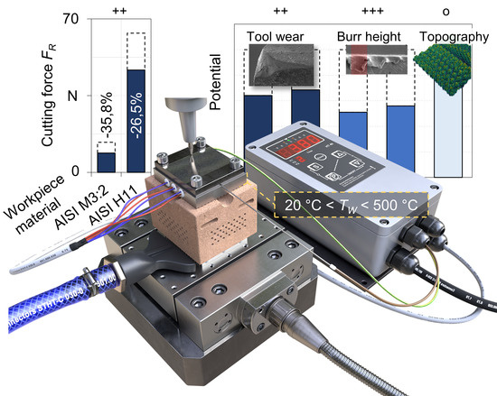
In this paper, the potential of a thermally assisted micromilling process using the principle of heat conduction was investigated. For this purpose, a prototype device was used in order to achieve the quasi-static homogeneous heating of the entire workpiece during the milling process. Experiments were carried out to analyse the influence of the workpiece temperature on the micromilling of hardened HSS AISI M3:2 (63 HRC). The focus lies on the cutting force, the resulting tool wear and the machined surface quality. Additionally, the results have been transferred to the thermally assisted micromilling of a HWS AISI H11 (52 HRC).
2. Materials and Methods
In the following sections, the experimental setup is described. The developed device for the thermally assisted micromilling process is explained in detail. Furthermore, the design of the experiments is introduced.
2.1. Experimental Setup
The investigation was conducted on a machine tool, KERN HSPC 2522. Due to the high working accuracy of 2.5 μm and the speed range of the spindle (VSC 4084 Precise), up to 50,000 rpm, the machine tool is highly suitable for micromilling processes. The acceleration of the axes is specified with a = 2000 mm/s² and a feed rate of vf = 6000 mm/min is available. In order to realise high accuracy, the machine tool was placed in a thermally controlled environment on a polymer concrete foundation to reduce the effects of heat and vibration.
In the course of the machining tests, end mills made of ultrafine grain carbide (grain size 0.5 μm) with a diameter of 1 mm were used for the process. Due to the cobalt content of 8% and the applied TiAlN-PVD coating, these tools are suitable for the machining task. The microgeometry of the cutting edge can be characterised by its average cutting edge rounding
= 1.1 ± 0.4 μm and a nominal corner radius of
rε = 50 μm. The workpiece material was a high-alloy HSS, AISI M3:2. In
Table 1, the specifications of the AISI M3:2 are listed. Due to the powder metallurgical production and a hardening to approximately 63 ± 1 HRC, this high-performance steel is suitable for the manufacture of components that can withstand high mechanical stress, such as dies and moulds [
25].
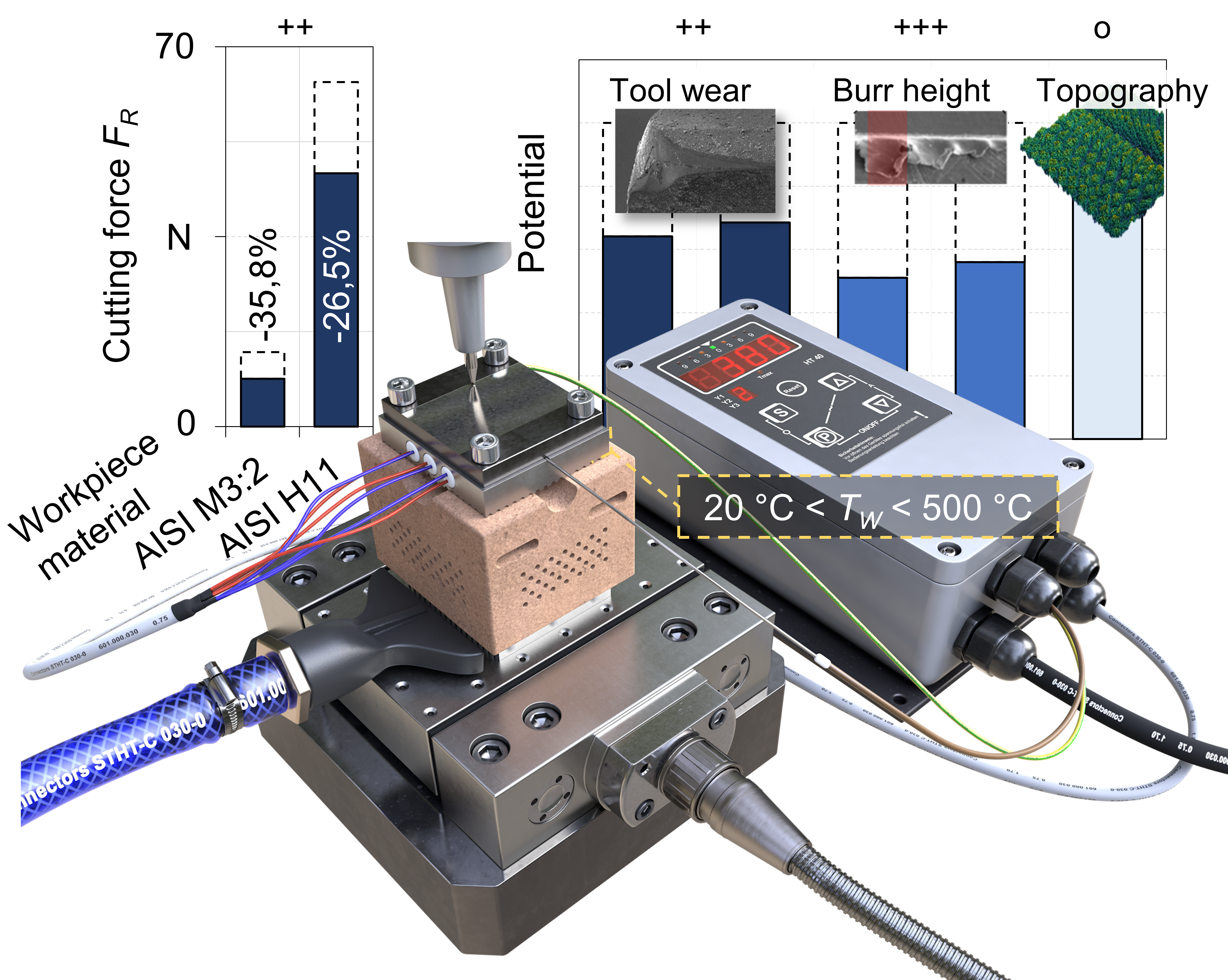
In order to achieve a defined workpiece temperature
TW, a device developed at the Institute of Machining Technology (ISF) for passive resistance heating was used; see
Figure 1. The device was constructed in three separate components, consisting of highly conductive aluminum and insulating ceramic parts. The process temperature is provided via a heating plate (a). Three cartridge heaters with a capacity of 200 W each were regulated by a HT40 Hillesheim temperature controller to realise a regulated and accurate workpiece temperature. The necessary isolation of the experimental setup was realised by the ceramic body (b). By inserting additional boreholes into the ceramic insulation body, the heat conduction path and the surface of the insulator could be increased to maximise the proportion of free convection. In addition to the passive insulator, an air nozzle dissipates the remaining heat from the system via a finned heat sink (c). Therefore, it was possible to generate a high thermal difference between the workpiece (up to 500 °C) and the connection to the machine tool (<30 °C). Convection-induced heat losses measured with thermocouples on the surface required a compensation of up to +20 °C. Furthermore, system tests showed a high homogeneity in the temperature field at the surface of the workpiece of Δ
T(
TW,500) < 20 °C. The thermal expansion in height during the machining process was in the range of Δ
h < 1 µm per minute, as soon as the appropriate heating time was exceeded. Accordingly, defined and constant machining conditions can be assumed during the entire machining process. A thermally assisted micromilling process could be realised with the shown experimental setup. Cutting forces were measured with the three-component dynamometer MiniDyn 9119AA2 (Kistler Group, Winterthur, Switzerland), with a sampling rate of 20 kHz. Using SEM and a digital light microscope, the wear of the tools was measured and analysed in iterative steps until the end of the machining process.
When evaluating the roughness of the workpiece, a white light microscope μsurf (NanoFocus AG, Oberhausen, Germany) was used to scan the machined surface. An additional point of investigation is the height of the top burr, which was measured with an Alicona Infinite Focus G5.
2.2. Design of Experiments
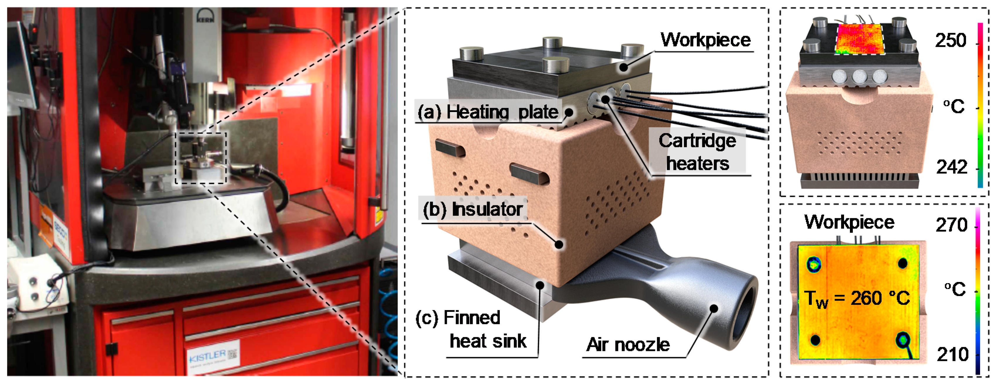
On the basis of previous investigations into the micromilling of the HSS AISI M3:2, suitable parameters have been defined in [
26]. This cutting parameter set was kept constant at a cutting speed of
vc = 120 m/min, depth of cut
ap = 0.025 mm, width of cut
ae = 0.4 mm and feed per tooth
fz = 0.025 mm. To analyse the influence of the thermal assistance on the micromilling process, the workpiece temperature was varied in the range
TW = 20–380 °C in steps of 120 °C. Each experiment was repeated three times with the respective parameter setting to ensure statistical verification within the limits of experimental accuracy. The process forces were measured with a single repetition after a tool path length of 72,990 and 1908 mm, whereby approximately 1600 tool engagements were analysed in each case. Tool wear and surface roughness were measured iteratively after tool path lengths of 2000, 3900, 5600, 7100, 8500 and 9700 mm and the burr height was analysed at
x = 8500 mm, with ten measured profiles per sample.
3. Results and Discussion
In this section, the results of the thermally assisted micro hard milling process by cutting the HSS are presented. In particular, the connection between cutting force and tool wear has been analysed and the aspects of surface quality and top burr are discussed. Finally, the transfer of the findings to a HWS AISI H11, which is commonly used in the hot forging industry, has been made.
3.1. Cutting Force
In the section that follows, the influence of a variation in the workpiece temperature on the resulting cutting force is presented.
Figure 2 depicts the determined cutting forces for three different temperatures
TW of the workpiece over the tool path length
x.
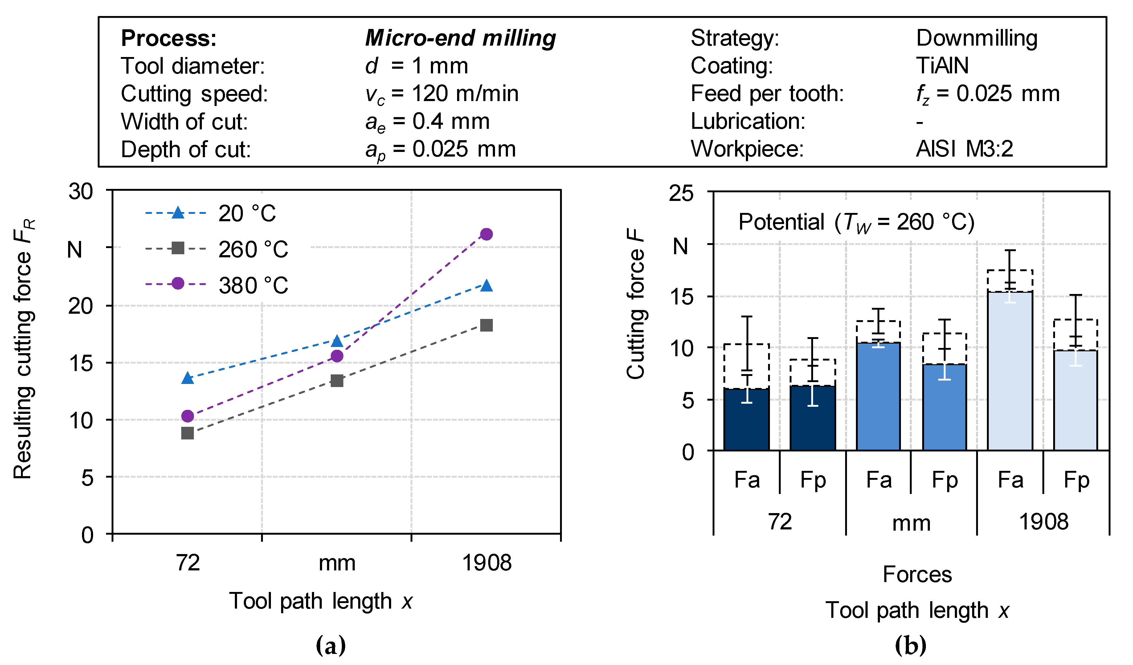
At the beginning of the machining process, a reduction in active Fa and passive Fp force components can be observed when increasing the workpiece temperature TW. Particularly, a workpiece temperature of TW = 260 °C led to a significant reduction in process forces compared to a machining at reference temperature TW,Ref = 20 °C. An overall reduction in the cutting forces from FR,20 °C = 13.7 N to FR,260 °C = 8.8 N (35.8%) at the beginning of the considered tool’s lifetime could be observed. This indicates a reduction in the yield strength by the induced process temperature, which lowers the shear resistance. For these processes, the additional process temperature and the heat generated during the machining process must be considered. As the tool path length x increases, the cutting forces rise due to the wear-related dulling of the cutting edge and the progression of wear. Compared to the process at room temperature, a high reduction in the axial component and a lower thermal effect on the active component of the cutting force can be measured. A consideration over the investigated tool path length of x = 1908 mm shows that the most significant reduction in the process forces could be achieved by regulating the temperature to TW = 260 °C. In contrast, a significant increase in process forces was determined for TW = 380 °C after a tool path length of x = 1908 mm, causing the cutting forces FR,380 °C to exceed those of the reference test FR,20 °C. This was related to the unfavourable constellation of the thermally induced ductility of the workpiece material and the wear-determined cutting edge of the milling tool becoming duller.
3.2. Tool Wear
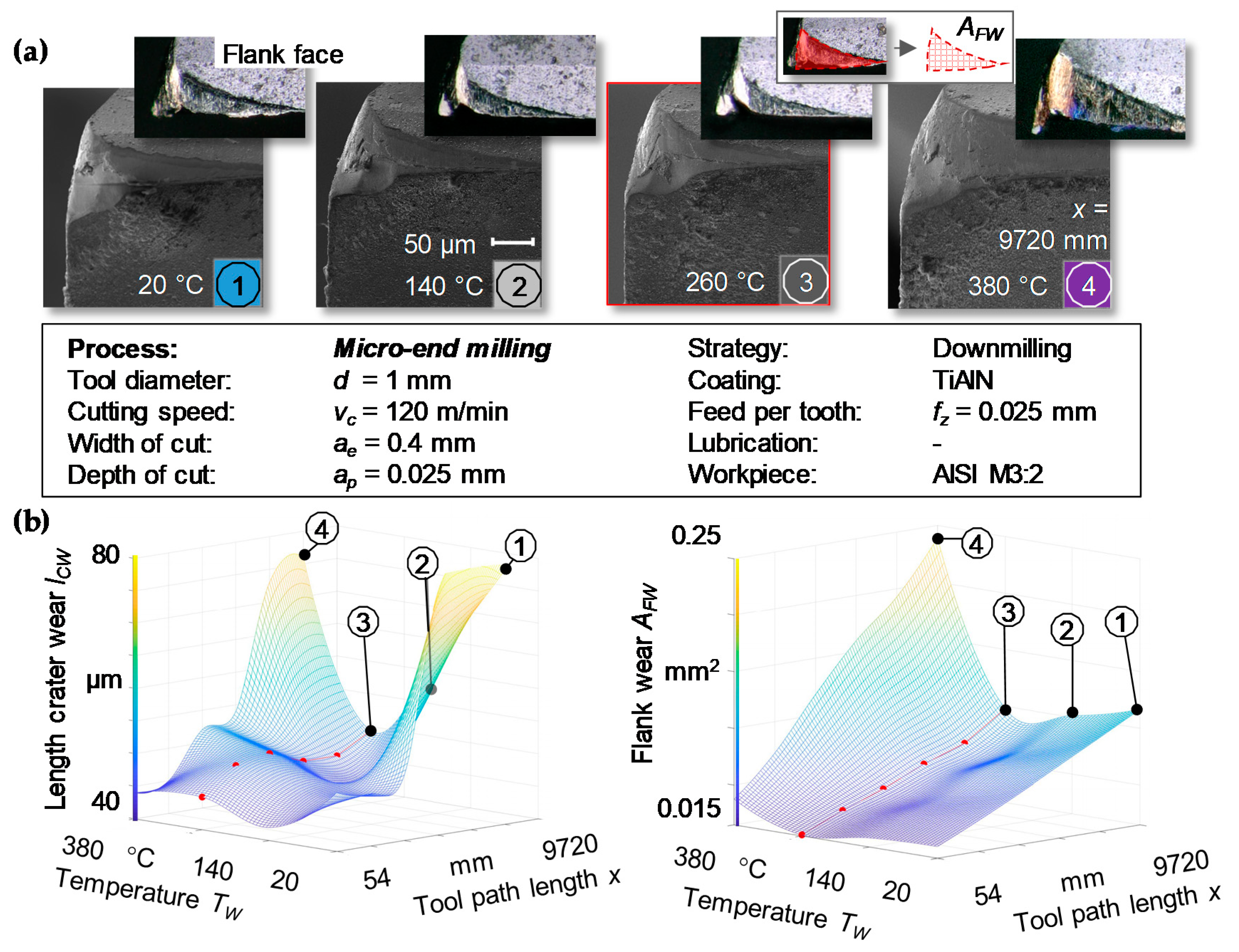
The machined HSS AISI M3:2 typically leads to extensive abrasive and adhesive effects that increase tool wear due to its high hardness and homogeneously dispersed carbides [
26]. This can also increase the occurrence of a flaking coating. Crater and flank wear are key indicators for assessing the stress of the tool during the machining process. As shown in
Figure 3, at a workpiece temperature of
TW = 260 °C, a reduction in the crater wear length from
lCW = 78 μm to
lCW = 50 μm (35.9%) occurs after a tool path length of
x = 5000 mm.
In addition, the thermal assistance of the machining process led, at the same temperature over the total tool path length x, to a lower rate of flank wear AFW. In particular, at the beginning of the considered tool life, these effects occur predominantly due to a reduction in the thermal softening of the workpiece material. As a result of a further increase in temperature, the colouring of the cutting edge of the tool gives us a reason to suspect oxidative effects. After a tool path length of x = 5508 mm at a workpiece temperature of TW = 380 °C, the strong wear of the coating and the increasing abrasive and adhesive wear of the substrate can be detected. However, a resultant dulling of the cutting edges and the removal of the edge at the cutting edge corner represent an adverse constellation in connection with the thermally ductile workpiece material. Due to the duller cutting edge, the proportion of plastic deformation increases.
The radical acceleration of the wear progression during tests with TW = 380 °C indicates that the increased process temperature represents the significant overstress of the coating system. Therefore, an adaptation of the coating system to a higher thermal resistance seems to be necessary to utilise the full potential of thermally assisted micromachining. Additionally, it can be assumed that the end mill tool geometry has a strong influence on the cutting fundamentals and wear progression. Further positive effects can be assumed at higher workpiece temperatures, as the material generally shows a reduction in material strength due to thermal softening at a temperature increase above 500 °C. Undesired changes in material properties, such as an increasing ductility, should be considered in order to achieve a suitable process.
3.3. Surface Roughness
Next, the results of the determined arithmetic mean roughness
Ra at varying process temperatures
TW are discussed. The surfaces machined were evaluated with a confocal white light microscope in combination with a 50× objective in order to analyse the influence of the thermal process assistance on the resulting surface quality.
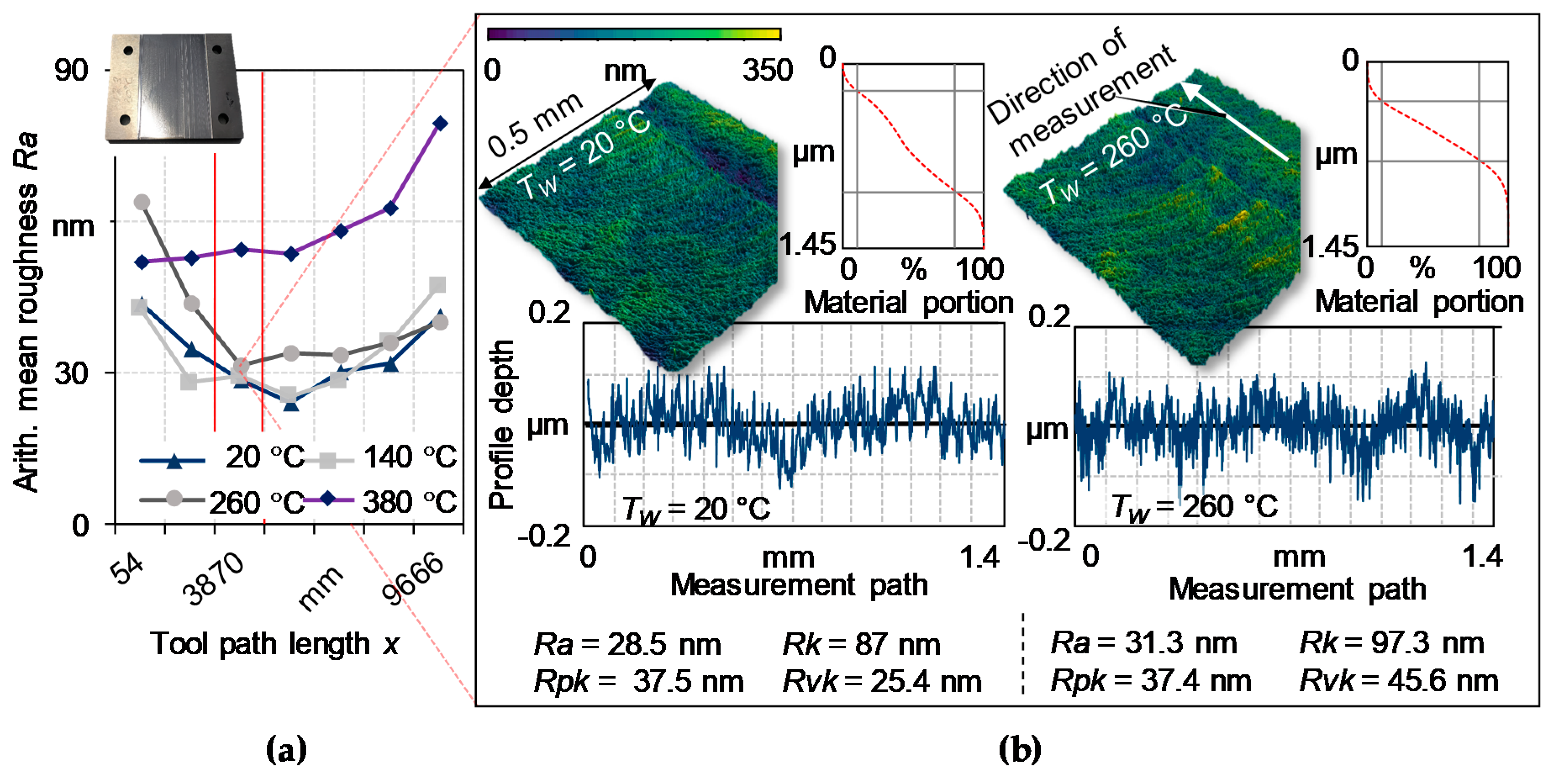
Figure 4 shows the detected surface roughness
Ra of the workpieces over the considered tool path length of
x = 9666 mm. In the experiments with process temperatures of
TW = 20–260 °C, the expected running-in of the tools can be observed at the beginning of the tool’s lifespan, which led to an improvement in the surface quality due to initial signs of wear. The roughness values determined in these experiments show a comparable profile and vary only marginally. However, due to the reduced wear progression with
TW = 260 °C and the minor increase in roughness after the initial wear, it can be assumed that this process design can ensure a high surface quality for a longer tool path length.
In the case of a workpiece temperature
TW = 380 °C, there are significantly higher values for the roughness
Ra in relation to the other tested temperatures. In particular, after a tool path length of
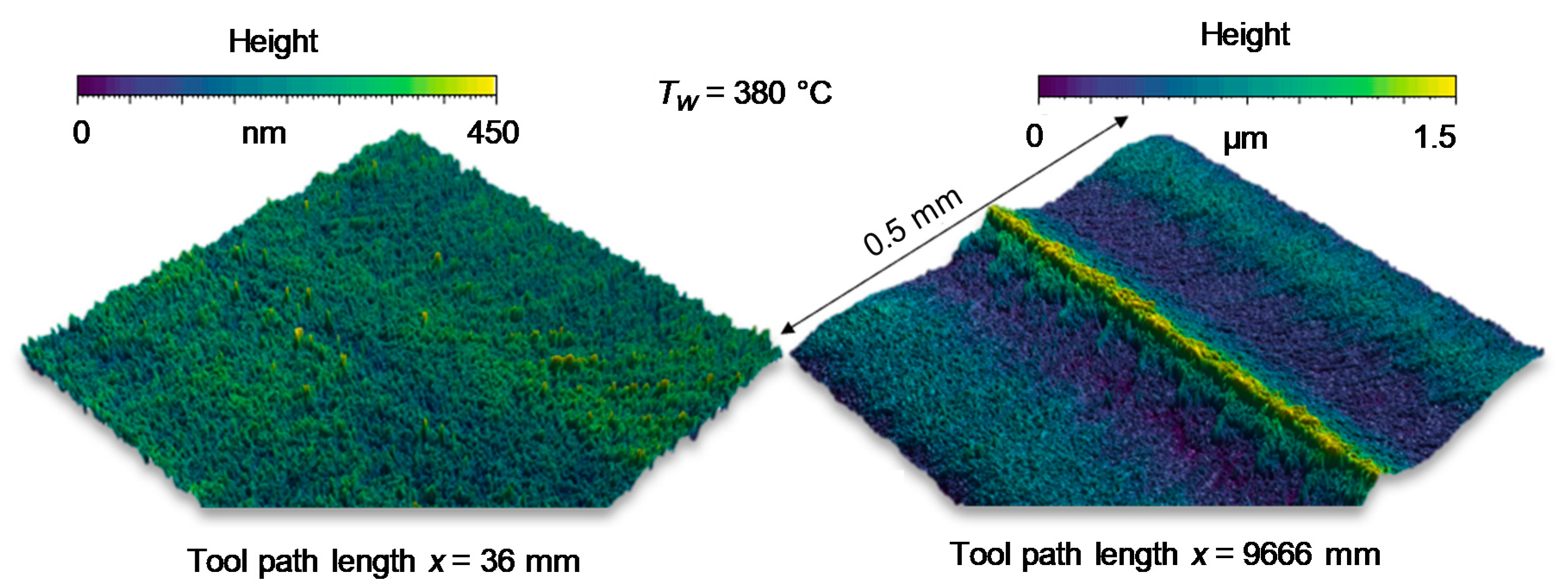
x = 7500 mm, due to the thermal impact, the accelerating wear rate favours an increase in roughness. A three-dimensional depiction of the topography at lower temperatures show characteristic cutting grooves that are related to the macro geometry of the engaging tool and the specific cutting parameters. In contrast, the machining grooves do not dominate the surface topography at higher temperatures, see
Figure 5. Instead, a fine roughness can be observed on the surface of the machining marks, which can be explained by the occurrence of oxidation processes. Oxidative effects can be assumed to build up oxide layers that lead to an increase in the surface roughness at higher temperatures. Future research can concentrate on preventing the thermally accelerated oxidation of the workpiece surface by means of additional inert gas assistance, thus reducing the roughness.
3.4. Burr Formation
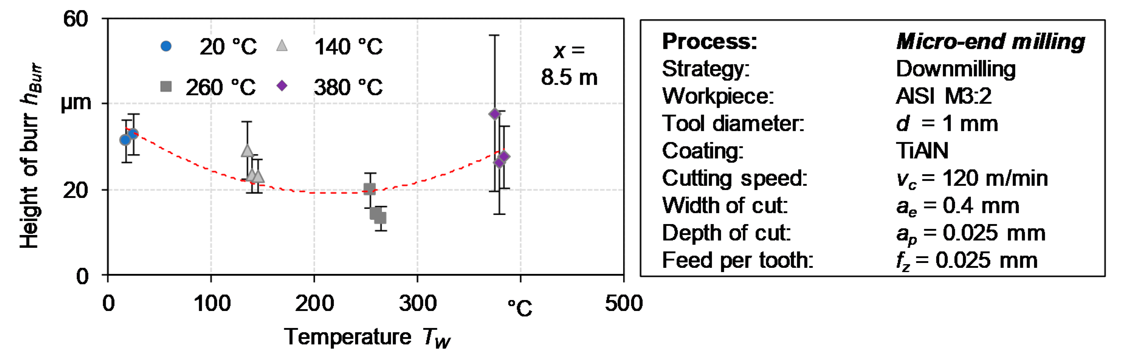
At the beginning of the machining process, the formation of the top burr is generally relatively low, as shown in
Figure 6. At
TW = 260 °C, no significant top burr could be detected on the workpiece. These findings may be confirmed by investigations on laser-induced oxidation-supported micromilling of the Ti6Al4V alloy, which showed a reduction in the top burr height by thermal process assistance [
27]. However, after a tool path length of
x = 8.5 m, both low workpiece temperatures and very high temperatures (
TW = 380 °C) resulted in the formation of top burrs and showed an increase in burr height.
Thermally assisted processing at TW = 260 °C led to the lowest increase and thus to a reduction in the burr height hBurr up to 15.8 μm, i.e., by 49% on average. In addition to thermal softening, which appears to have a positive effect on the upper burr height hBurr, the associated tool wear has a strong influence on burr formation due to the amount of plastic deformed material in front of the dulled cutting edge. A further increase in temperature to 380 °C therefore led to an increase in burr height hBurr to the maximum value due to the highest wear rate and the increasing ductility of the workpiece material.
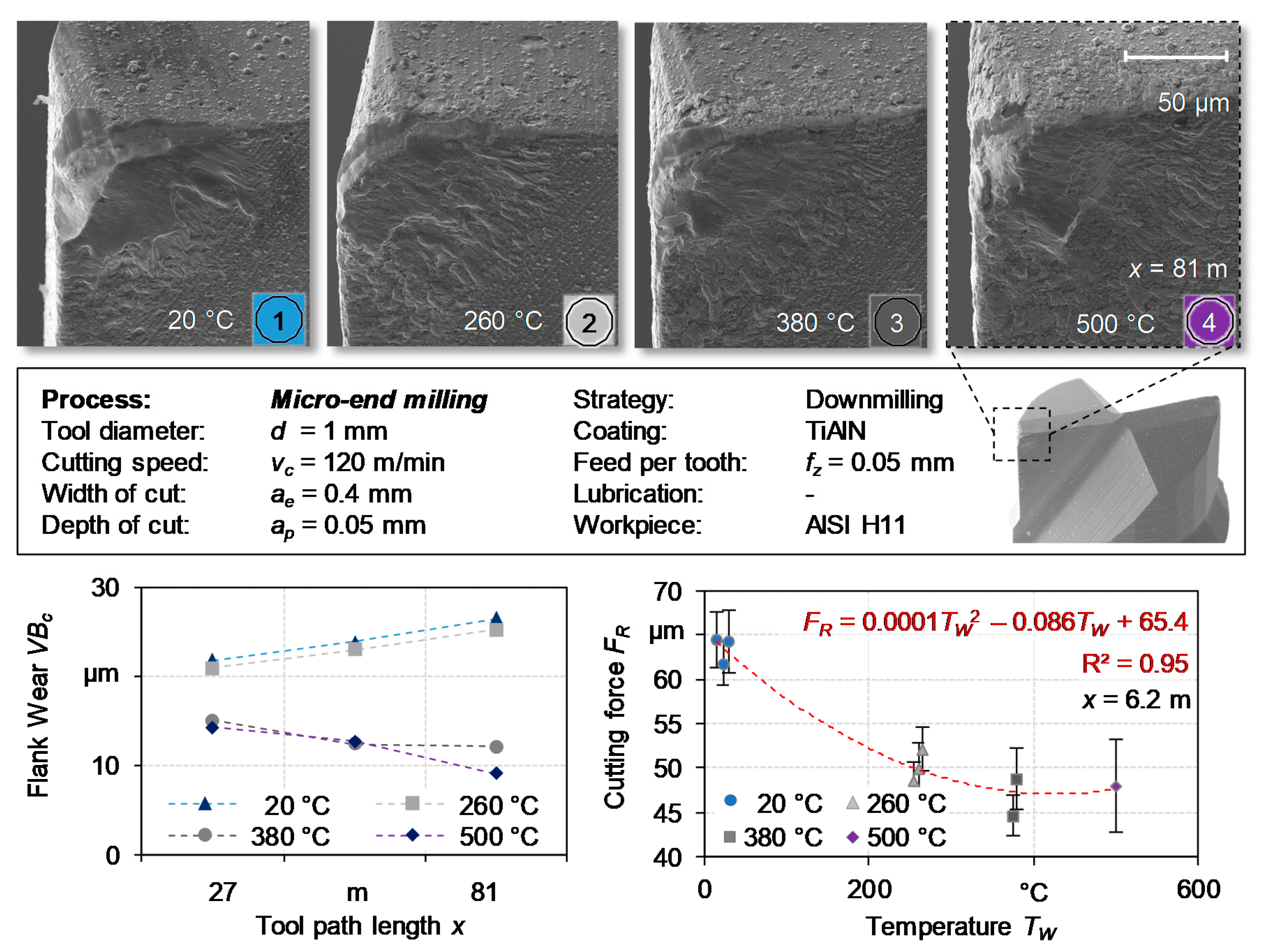
3.5. Transfer of the Thermally Assisted Micromilling to the HWS AISI H11
The relevance of thermally resistant materials for the forging industry gives us a reason to transfer these findings for the thermally assisted micromilling of HSS in order to evaluate the potential machining of HWS (AISI H11). Therefore, experiments have been carried out with the same micro-end milling tool and similar parameter settings. To investigate thermal effects near the limit of the process, the depth of cut
ap and the width of cut
ae were increased to 0.05 mm. The temperature was varied from
TW = 20–500 °C in steps of 120 °C. The machining process was repeated three times for each parameter setting, except for the temperature
TW = 500 °C, which was carried out once to confirm the tendency observed. The tool path length was set to 81 m for the investigation. The process forces were measured after a milling path of 6.2 m. The tool wear was recorded at the tool path length of 27, 54 and 81 m and the burr height was measured at
x = 61.15 m.
Figure 7 shows the results of the measured process forces and the analysed tool wear. Experiments at a reference workpiece temperature of
TW = 20 °C showed a significantly lower tool wear compared to the micromilling of HSS (AISI M3:2). The lower hardness of the workpiece material of 52 HRC (AISI M3:2, 63 HRC) lead to a better machinability. However, damage to the tool coating and crater wear of the carbide body can be detected, especially when machining at reference temperature. Compared to micromilling AISI H11 at a reference temperature, at temperatures up to
TW = 260 °C small differences in abrasive tool wear were observed.
Furthermore, a positive influence can be seen due to fewer chipping in the tool’s cutting edge. An increase in workpiece temperature to
TW = 380 and 500 °C showed a distinct reduction in the measured flank wear
VBc. Considering the images of the tools shown in
Figure 7, it can be stated that the proportion of adhesive effects rises with the increasing workpiece temperature. However, this reduces the possibility of sufficiently evaluating other wear mechanisms. Therefore, further investigations are necessary to discover the full potential of the thermally assisted micromilling. Due to the oxidative effects, further investigations of the surface topography have been waived.
An investigation into the determined process forces showed a strong correlation with the tool wear progression. Up to TW = 380 °C, the additionally induced process temperature seems to have a strong effect on the resulting process forces. A reduction in cutting forces up to 26.5% were observed. This correlated with the reduction in tool wear. Compared to the machinability of the investigated HSS AISI M3:2, the HWS showed the strongest effects on wear and cutting forces at a workpiece temperature of TW = 380 °C.
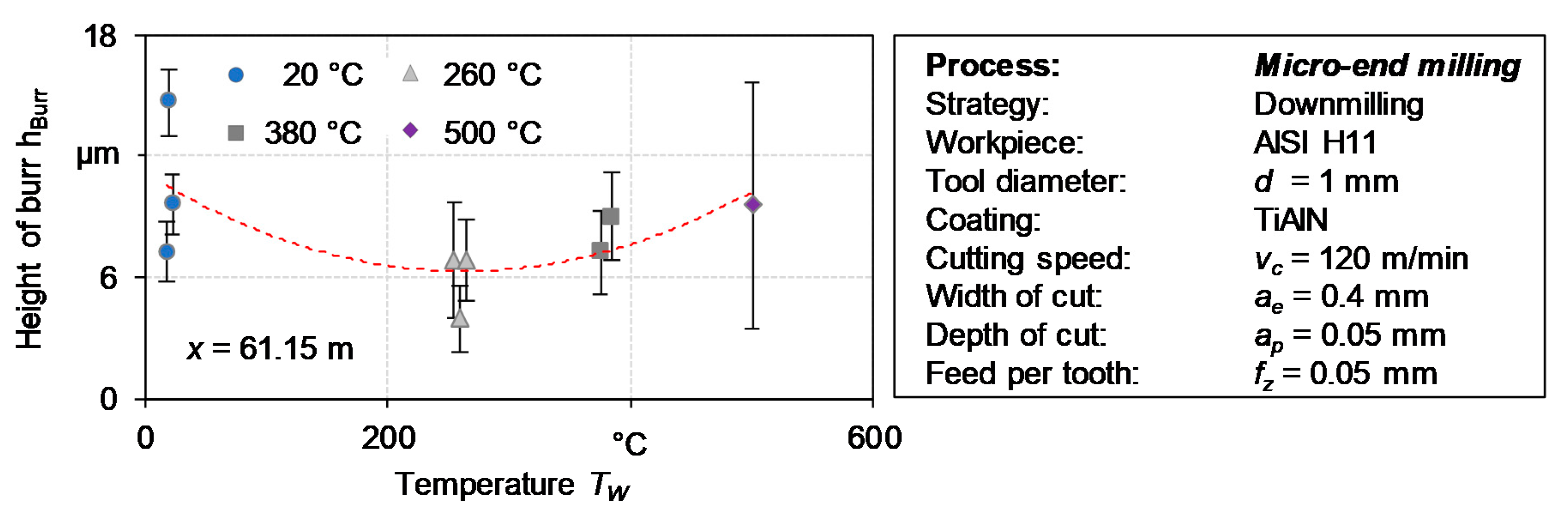
Similar effects can be seen in the formation of upper burrs, as shown in
Figure 8. With increasing tool path length, up to
x = 61.15 m, the upper burr height
hBurr was reduced from 10.7 to 6 μm (44%) due to thermal process assistance. The minimum burr formation was achieved by a workpiece temperature of
TW = 260 °C. A further increase in the workpiece temperature
TW resulted in a higher top burr formation, which may be connected to the higher ductility of the workpiece material. Compared to the investigated HSS, the high wear-related burr formation does not appear to the same extent due to the lower rate of tool wear. The previously measured extreme height of the top burr can therefore not be found here. As a result of the differences in tool wear, the comparability is low. Nevertheless, there is a tendency toward a similar potential.
4. Conclusions
The micromilling of difficult-to-machine materials like HSS requires new technologies to enable an efficient machining process and a high manufacturing quality. Hybrid processes like the thermally assisted micromilling offer great potential due to the temporary effect of the thermal softening of the workpiece material. For this reason, an innovative approach for thermal process assistance by heat conduction was developed with a prototype, which enables the precise control of the workpiece temperature and ensures constant cutting conditions. The significant impact of the thermal process assistance on the micromilling of AISI M3:2, as well as a comparison of these findings to the thermally assisted micromilling of the HWS AISI H11, were shown by the conducted investigations, as illustrated in the following.
Positive:
Regulating the workpiece temperature to TW = 260 °C led to a strong reduction in the resulting cutting force FR,260 °C up to 35.8% (AISI M3:2);
Elevating the workpiece temperature in the area of 380 to 500 °C led to a max. reduction in cutting forces FR up to 26.5% (AISI H11);
A decrease in tool wear can be achieved for a workpiece temperature TW = 260 °C/380 °C (AISI M3:2/AISI H11);
A significant reduction in the top burr height hBurr at TW = 260 °C (49/44%; AISI M3:2/AISI H11) was achieved.
Negative:
The undesired occurrence of oxidative layers hinders a correct analysis of the achievable surface topography;
A workpiece temperature of TW = 380 °C led to an increase in tool wear when HSS was machined (AISI M3:2);
The number of adhesive effects changes the wear pattern and therefore the significance of the results slightly (AISI H11).
In summary, it can be shown that this thermally assisted micromilling process with homogeneous workpiece heating has a high potential for machining difficult-to-machine materials. The new approach enables the supported machining of highly complex shapes with complicated machining motions, which is limited in laser-assisted processes by the accessibility of interfering contours. In addition, constant cutting conditions and a reduction in heat-affected zones offer great advantages in in terms of process stability and surface quality due to the comparatively low surface temperatures of the workpiece. The principle of heat conduction offers a simplified and cost-effective alternative for the precise temperature setting of the workpiece and, due to the high flexibility of the tool-related material removal rates, ideal conditions for basic research. Based on the detected wear progressions, the adjustment of the tool coatings regarding the thermal durability seems to be partially necessary and could further increase the potential of the presented approach.


