Design of Chatter-Resistant Damped Boring Bars Using a Receptance Coupling Approach


Machine Tool Dynamics Laboratory, Department of Mechanical Engineering, Indian Institute of Technology Kanpur, Kanpur 208016, Uttar Pradesh, India
*
Author to whom correspondence should be addressed.
J. Manuf. Mater. Process. 2020, 4(2), 53; https://0-doi-org.brum.beds.ac.uk/10.3390/jmmp4020053
Submission received: 18 April 2020
/
Revised: 25 May 2020
/
Accepted: 1 June 2020
/
Published: 3 June 2020
(This article belongs to the Special Issue Machine Tool Dynamics)
Abstract
:Deep hole boring using slender bars that have tuned mass dampers integrated within them make the boring process chatter vibration resistant. Dampers are usually designed using classical analytical solutions that presume the (un)damped boring bar which can be approximated by a single degree of freedom system, and the damper is placed at the free end. Since the free end is also the cutting end, analytical models may result in infeasible design solutions. To place optimally tuned dampers within boring bars, but away from the free end, this paper presents a receptance coupling approach in which the substructural receptances of the boring bar modelled as a cantilevered Euler–Bernoulli beam are combined with the substructural receptances of a damper modelled as a rigid mass integrated anywhere within the bar. The assembled and damped system response thus obtained is used to predict the chatter-free machining stability limit. Maximization of this limit is treated as the objective function to find the optimal mass, stiffness and damping of the absorber. Proposed solutions are first verified against other classical solutions for assumed placement of the absorber at the free end. Verified models then guide prototyping of a boring bar integrated with a damper placed away from its free end. Experiments demonstrate a ~100-fold improvement in chatter vibration free machining capability. The generalized methods presented herein can be easily extended to design and develop other damped and chatter-resistant tooling systems.
1. Introduction
Deep hole boring necessitates the use of long and slender cantilevered boring bars with length to diameter ratios typically being five and higher. On account of being long, slender, and cantilevered, and because of their inherently low structural damping, the boring bars tend to vibrate with large amplitudes under the action of cutting forces. Such process-induced large amplitude vibrations often result in chatter vibration related machining instabilities. Chatter deteriorates surface finish and results in high tool wear or breakage, thereby limiting productivity, precision, and material removal rates. To make boring processes chatter-resistant, boring bars must possess improved dynamic stiffness and damping behavior. This paper attempts to address this requirement by presenting a new method to optimally tune and integrate absorbers within boring bars to improve their damping behavior.
Since boring to enlarge and finish holes remains an important machining operation in the manufacture of several important industrial components, there has been substantial research and industrial effort at developing more stable and chatter-resistant damped boring bars. These efforts have centered on: the use of materials with higher strength and damping [1,2,3,4,5,6]; the use of passive dynamic vibration absorbers, including the methods of tuned mass dampers [7,8], impact dampers [9,10,11,12,13,14,15,16,17] and/or particle dampers [18,19,20]; and the use of (semi)active vibration control means using piezoelectric and/or electromagnetic actuators [21,22,23,24,25,26,27], and/or methods using electro-rheological fluid [28] and magneto-rheological fluids [29,30,31,32,33,34,35].
Even though active systems can sometimes outperform passive ones, in most cases, a well-designed passive dynamic vibration absorber is preferred due to its simplicity, ease of implementation, no need for external energy source, low costs, and industrial viability. For these reasons, tuned mass dampers are generally preferred over other passive damping methods. Industrial efforts too at making passively damped boring bars have followed the developments reported in patents filed as early as in the 1970s [36,37,38,39], with almost all major cutting tool manufacturers having their own version of a boring bar with a tuned mass damper; see, for instance Silent ToolsTM from SANDVIK Coromant [40] or KMTM Tunable Bars from Kennametal [41] or ISCAR’s Whisperline tools [42], or solutions from Mapal [43].
The central idea in tuned mass dampers (vibration absorbers) is to attach a carefully chosen secondary oscillator to a primary oscillator such that some vibratory energy of the primary system is transferred to the secondary system for dissipation. The design of tuned mass dampers hence concerns optimally selecting the mass, stiffness, and damping of the absorber (damper) such that it helps dissipate energy from the primary system.
Tuning is generally based on the classical analytical method proposed by Ormondroyd and Den Hartog [44,45] which seeks to minimize the magnitude of the frequency response function (FRF) of the combined system. Since this classical analytical method [44,45] was for the special case of the primary system being undamped, improvements considered the primary system being viscously damped [46,47,48], and/or viscoelastically damped [49,50]. Since the critical chatter-free cutting conditions for simple orthogonal cutting models and/or turning models are inversely proportional to the real part of the FRF [51], analytical methods proposed by Sims [52] are also oft-used since the method seeks to find optimal damper parameters by minimizing the negative real peak of the FRF. Sims [52] also reported results with the primary system being damped using numerical optimization schemes. All classical analytical methods of tuning the absorber [44,45,46,47,48,49,50,51,52] approximate the dynamics of the primary system by an (un)damped single degree of freedom system model. While this is a reasonable assumption for most long and slender cutting tools, this assumption always presumes attachment of the damper at the free end of the cantilevered tool, which is also the cutting end, and hence any design solution may not necessarily be feasible and/or practically realizable.
Since absorbers must be placed away from the free end, Moradi et al. [53], Miguelez et al. [54] and Rubio et al. [55] presented methods to integrate the absorber with the boring bar modelled as a continuous Euler–Bernoulli beam, and hence they were able to tune the absorber parameters for when it is placed anywhere on the beam. Though these methods [53,54,55] were able to position the damper anywhere on the boring bar, they modelled the boring bar as a solid beam. Since the absorber must be integrated within the beam, the beam must be modelled as locally hollow, and since the response of a solid beam and a locally hollow beam is undoubtedly different, and since tuning of the absorber’s parameters depends on the response of the primary system, even though earlier methods could account for tuning the absorber for placing it anywhere on the beam, design solutions resulting from them may also not be feasible.
To address the need for a generalized method to help develop optimally tuned and damped chatter-resistant boring bars that includes damping in the boring bars as well as optimizes parameters for placing the absorber away from the free end and anywhere within the boring bar, this paper presents a new receptance coupling (RC) based method. Methods presented herein build on our preliminary work [56,57]. Though our earlier work outlined the receptance coupling approach, the boring bar was modelled as a solid beam in earlier work, and not locally hollow—as it must be, and as is undertaken herein. Furthermore, our earlier reported work offered no experimental validation. This paper will overcome both shortcomings by presenting an expanded analytical treatment and will also discuss how the proposed model guides prototyping and experiments.
Receptance coupling is a structural modification tool and is used to couple two separate subsystems in the frequency domain [58] using their individual component level receptances, i.e., frequency response functions (FRFs). Receptance coupling methods have found much use in machine tool applications to predict tool point dynamics [59,60,61,62] under changing tool and tool-holder configurations, by treating the tool and tool-holder as separate individual subsystems whose receptances can be measured and/or modelled, and that can be coupled with the measured and/or modelled receptances of the machine’s spindle. Receptance coupling methods have also been used in recent works to design absorbers to damp machine tool structural vibrations [63,64]. A receptance coupling approach was also successfully used in [65] to rigidly couple a boring bar modelled as a free-free beam to a flexible holder to evaluate the influence of the holder’s stiffness and damping on the assembled system receptance to help tune the holder to improve the dynamic stiffness of the boring bar.
In the present work, receptances of two substructural systems, the boring bar (subsystem I), and the tuned mass damper (subsystem II) placed anywhere () within the boring bar of length , and diameter, as shown in Figure 1, are combined (damper of mass is coupled with a spring, and a damper, ) to obtain the optimized damped response at the free end of the tool.
The receptance coupling approach can work with modelled and/or measured receptances. Section 2 first presents the model-based approach, and Section 4 demonstrates the method with measured receptances. For the model-based approach, the boring bar is modelled as a damped cantilevered Euler–Bernoulli beam. The model accounts for the beam being locally hollow to account for the absorber being placed inside it, and hence also address the shortcomings of the methods in [53,54,55]. Substructural receptances of the boring bar are combined with the receptance of a rigid mass connected to the boring bar using a stiffness and damper to obtain the assembled system response. Since the chatter-free machining stability limit in boring processes is governed by the assembled response of the boring bar in the radial direction (the X direction in Figure 1) [66,67], the absorber to be integrated within the beam is also assumed to be connected to the beam only in the X direction using elastic elements as shown schematically in Figure 1, and maximization of the chatter-free stability limit is treated as the objective function to find the optimal mass, stiffness and damping of the absorber. To compare our findings with other classical methods [2,44,45,46,52,53], another objective function that minimizes the negative peak of the real part of the assembled receptance to find optimal absorber parameters is also discussed. We use a numerical optimization scheme based on the minimax method [68,69], and though we incorporate the influence of the cutting insert and nose radius, our focus during optimization is more on the structural design aspects. All analysis presented herein is for the case of a stationary boring bar with a rotating workpiece.
Section 3 contrasts predictions using the proposed receptance coupling approach with other classical methods of Rivin and Kang [2], Ormondroyd and Den Hartog [44,45], Asami et al. [46], and by Sims [52], and with results obtained with the method proposed in [53] that also model the boring bar as a continuous beam. These comparisons assume placement of the absorber at the free end to verify the newly proposed method. Section 3 also discusses how the optimized absorber parameters change with changing placement location of the absorber within the beam. This is followed by discussions on how, for assuming placement of the absorber at a fixed location inside of the bar, the chatter-free machining stability limit changes with absorber parameters.
Model-based investigations guide prototyping of a boring bar with an absorber placed inside it, and Section 4 presents experimental results with the prototyped bar. Section 4 also discusses the use of the measured receptances in an inverse manner to identify the absorber parameters and contrasts these results with model predictions. Section 5 discusses cutting experiments with and without a damper integrated within the prototyped boring bar and demonstrates how a damped boring bar can improve the chatter-free cutting ability. This is followed by the main conclusions of the paper.
2. Receptance Coupling Method for Boring Bars Integrated with an Absorber
This section first presents the receptance coupling formulations, which is followed by describing model-based methods to obtain receptances of the boring bar, and of the tuned mass. This is followed by describing the objective function to maximize the chatter-free machining stability limits, and to minimize the negative peak of the real part of the assembled receptance.
2.1. The Receptance Coupling Method
The boring bar modelled as a clamped-free Euler–Bernoulli beam is treated as subsystem I, and the tuned mass of the damper is treated as subsystem II, as shown in Figure 1 and Figure 2. Schematic coupling of the absorber to the boring bar is shown in Figure 2a, and a schematic of coupling two equivalent dynamical systems is shown in Figure 2b. Since the chatter-free machining stability limit in boring processes is governed by the assembled response of the boring bar only in the radial direction (the X direction in Figure 1 and Figure 2a), the absorber to be integrated within the beam is also assumed connected to the beam only in the X direction using a spring and damper connection as shown in Figure 1 and Figure 2a. Moreover, since the boundary conditions for the beam are assumed to be clamped-free, and since the beam is assumed to be flexible only in the radial direction, i.e., since we ignore the axial and torsional vibrations, we also ignore the influence of rotational degrees of freedom during the receptance coupling procedure, and instead couple the two subsystems using a linear spring and damper connection as shown in Figure 1 and Figure 2.
The coupling location where the mass of the absorber is attached using a spring and damper connection, as shown in Figure 1 and Figure 2a, is location 2a, which may correspond to any location along the length of the bar. Location 1 is the free end (cutting end) of the boring bar where the response is to be predicted and optimized by tuning the absorber. For locations, see Figure 1 and Figure 2a.
The absorber (subsystem II) integrated within the boring bar modelled as a cantilevered beam (subsystem I) is assumed connected along the central axis of the beam with a spring of stiffness N/m and a dashpot damper of damping N-s/m to form the assembly, III. The subsystems are coupled at coordinates and belonging to subsystems I and II, respectively. Our interest is in getting the assembled response at the location in III which is at the same physical location as in the subsystem I. Though there is relative motion between the absorber and the beam due to the flexible coupling between them, since the absorber is connected to the beam along the beam’s central axis, the assembly locations and appear to be the same in the schematic in Figure 2a, and the coupling between these locations is instead shown in Figure 2a by a representative spring and damper between the absorber’s mass and the boring bar. Since it is difficult to characterize the relative motion at the coupling location between the absorber and the beam, the procedure to obtain the synthesized response is better explained by way of coupling two equivalent dynamical systems as represented in Figure 2b, in which, subsystem I is still the beam, and the subsystem II is the absorber’s mass.
We assume that direct receptances and and the cross receptances and for I, and for II are known a priori. For such a system, component displacement for the subsystem I with two forces can be written as:
and, for subsystem II, we have,
To determine the direct response at location of the assembled structure, it is assumed that only one harmonic force is applied to the assembled system III and all other forces are zero. In this case, response can be simply written as: , which gives .
Force equilibrium conditions at the interface and free end are: and , respectively. Furthermore, displacement compatibility at the interface is:
The assumption of harmonic motion due to the application of a harmonic force , allows us to express velocity dependent damping forces in the form of . Equation (3) can hence be rewritten as:
Equation (4) is equivalent to , where . Substitution of component displacement and force equilibrium conditions in Equation (4) results in:
Applying the equilibrium condition, , we obtain:
This enables us to write the assembled receptance at the free end as [58]:
wherein is the receptance at the free end for the original boring bar, i.e., at location 1, is the receptance at the coupling location of the absorber for the original boring bar, and are the cross receptances between the free end and the coupling location of the absorber, again for the original boring bar, and since the structure is symmetric and assumed to be linear, these cross receptances are the same and equal, is the tunable receptance of the absorber, and is the effective complex stiffness. Though receptances in Equations (1) and (2), and in Equations (5)–(7) are frequency dependent, is omitted from all these equations for brevity. The subsystem level receptances for the original boring bar and the tuned mass damper are obtained as discussed below.
2.2. Obtaining Receptances of the Boring Bar
For the model-based investigations herein, the receptances of the boring bar are obtained by modelling it as a damped cantilevered Euler–Bernoulli beam that is cylindrical and symmetric. The assumed clamped-free boundary conditions for the boring bar modelled as a Euler–Bernoulli beam are consistent with other similar modelling approaches for slender boring bars [6,23,29,53,54,55,70,71,72,73], and though the tightening torque, number and size of clamping screws, and the order of tightening the screws in real holders supporting slender boring bars do influence their boundary conditions and their dynamics [74], for investigations herein, the clamped-free model is thought to be adequate.
The model presented below expands on the beam formulations presented in [53,54,55] by accommodating for the beam to be locally hollow to house the damper inside it. The boring bar with length , density , outer diameter , and with an elastic modulus , with one end fixed and the other end free can be thought to be made of three parts as shown in Figure 3, with part 2 being hollow to accommodate the absorber. The response of the bar is desired to be obtained for when it is subjected to a cutting force, acting at a location measured from the fixed end.
The governing equation of motion of a damped Euler–Bernoulli cantilevered beam with clamped-free boundary conditions describing the transverse motion in the radial direction while neglecting effects of rotary inertia and shear deformations, and ignoring the tangential, axial, and torsional vibrations of the slender boring bar, using the Hamilton’s principle, can be shown to be [75]:
wherein is the cross-section area of the beam, is the area moment of inertia of the beam, is the deflection of the beam in the -direction, is the damping coefficient of the boring bar, is a Dirac delta function, and the value of ‘’ depends on the part of the beam considered, i.e., 1, 2 or 3.
Consider a modal solution (for modes) for the undamped form of Equation (8) of the form of:
wherein represents the time component of the displacement, and are the undamped mode shapes that are different for every section of the beam, such that:
and, the corresponding undamped natural frequencies are [75]:
The boundary conditions for the beam are listed below, and show the slope and deflection at the clamped end to be zero, and that the shear force and bending moment at the free end are also zero:
Furthermore, the compatibility conditions at the interfaces ‘’ and ‘’ (see Figure 3) to ensure continuity are:
wherein the superscripts, ‘−’ and ‘+’ denote positions slightly before and after the interfacial point(s).
Modal solutions to Equation (8) require the twelve unknowns (, for to 3) in the mode shape equation (Equation (10)) to be satisfied by the twelve equations from the four boundary conditions in Equation (12) and the eight compatibility conditions in Equation (13) to result in a transcendental equation in β with infinite solutions. In the domain of ℝ+, the first solution corresponds to the first mode, and the second solution corresponds to the second mode, and so on.
To obtain the desired receptances, the orthogonality property of the mode shape is used, and the equation of motion is rewritten as [75]:
wherein
Assuming the excitation and response are both harmonic, i.e., and , Equation (14) can be re-written as:
Pre-multiplying Equation (15) with , the frequency response function matrix for the beam can be written as:
wherein, is response location and is the excitation location. The subscript 1 in Equations (14)–(16) corresponds to only the first mode being considered. Since the receptance coupling formulation requires the receptances at the free end of the boring bar, i.e., at location 1, and at the location where the damper is to be integrated within the boring bar, i.e., at location 2a, these can be easily obtained using Equation (16), by choosing and appropriately. Additionally, the cross receptance between locations 1 and 2a can also be accordingly obtained. Having described how to obtain four of the five receptances necessary to find the assembled receptance (see Equation (7)), the receptance of the tuned mass is obtained as described next.
2.3. Obtaining the Receptance of the Tuned Mass
The receptance of the tuned mass, is simply:
Having obtained receptances for both the boring bar (subsystem I), and the tuned mass (subsystem II), these can be combined as in Equation (7) with appropriate values of the complex stiffness , to predict the assembled system response at the free end of the boring bar.
2.4. Setting up the Optimization Problem
Since the damped boring bar is being designed to make possible chatter-free machining, maximization of the chatter-free stability limit is treated as the objective function. Since the slender boring bar is often more flexible than the workpiece it is used to bore, and since the depths of cut in boring are often of the order of the nose radius, the absolute minimum chatter vibration-free depth of cut can be estimated by the so-called ‘1D solution’ model in which the nose radius is accounted for and the flexibility of the boring bar in the radial direction (the X-direction in Figure 1 and Figure 3) is used to estimate the limiting speed-independent depth of cut, as [66,67]:
wherein is the real part of the eigenvalue, , i.e., , and the eigenvalue in turn is expressed as: , wherein is the assembled receptance at the free end. within Equation (18) is the ratio of the imaginary and real parts of the eigenvalue , i.e., . is the element height, assuming that the nose radius () on the cutting insert is divided into trapezoidal elements, such that , and , wherein is the equivalent side cutting edge angle. and within Equation (18) are elemental directional coefficients that are a function of , , and the radial cutting force coefficient , and are obtained as defined in [66,67].
Since Equation (18) clearly shows the limiting depth of cut in boring processes to be governed by the assembled system response at the free end, the optimization problem is setup such as to find the appropriate parameters of the stiffness, and damping, of the damper for a given mass, , that maximizes the chatter-free stability limit. The objective function is hence defined as:
wherein is the ratio of natural frequency of the absorber to the natural frequency of the dominant mode of the primary system, and is the damping ratio for the absorber.
Since we also verify our proposed receptance coupling approach with the other classical methods of tuning absorber parameters [52], to make such comparisons meaningful, we also setup an optimization problem as in the other studies [52], wherein the objective function minimizes the negative peak of the real part of the assembled receptance to find optimal absorber parameters. In which case the objective function in Equation (19) is replaced by:
wherein and are the same as described above.
3. Model-Based Results
This section first demonstrates the workings of the proposed receptance coupling method, followed by contrasting predictions using the proposed scheme with the results of other classical methods of optimally tuning the absorber, assuming that the absorber is placed at the free end. Having verified the proposed method, we then discuss how the optimized absorber parameters change with changing placement location of the absorber within the beam. This is followed by discussions on how, for assuming placement of the absorber at a fixed location inside of the bar, the chatter-free machining stability limit changes with absorber parameters.
3.1. Demonstrating the Workings of the Receptance Coupling Approach
As an example of how the substructural receptances can be combined to obtain the assembled receptance, and how both methods of optimization, i.e., maximization of the chatter-free depth of cut, and minimization of the negative peak of the real part of the assembled receptance result in potentially different damped responses of the assembled boring bar and correspondingly different optimal parameters of the tuned mass damper, consider a boring bar approximated as a cantilevered beam made of steel with a density of kg/m3, a modulus of GPa, a length of 200 mm, and a diameter of 25 mm (), with the hollow section placed at a distance of 90 mm from the fixed end. The cavity has a diameter of 16 mm, and a length of 55 mm. The structural damping coefficient of the boring bar is assumed to be 46.5 N-s/m. An absorber of mass 0.135 kg is assumed placed at length of ~120 mm from the fixed end (), and it is coupled to the boring bar using an arbitrarily chosen spring and damper with a stiffness of N/m and a damping coefficient of 78 N-s/m, respectively. For maximizing the chatter-free depth of cut, we assume cutting of Aluminium with a cutting insert that has a nose radius of 0.4 mm, and a side cutting edge angle of 3°, and the radial cutting force coefficient is assumed to be 580 N/mm2. The number of trapezoidal elements to adequately describe the nose are taken to be 1000.
The substructural receptances for the boring bar with the given specifications, and for the absorber with the given mass are shown in Figure 4, which also shows the assembly receptance at the free end of the boring bar. This assembly receptance is optimized using both methods to find the optimal stiffness and damping, and the resulting optimized receptances at the free end are also shown in Figure 4. Since all receptances are complex valued, Figure 4 shows their real and imaginary parts. Analysis herein is limited to discussing only the first fundamental bending mode of the boring bar, which is usually also the most flexible.
As is evident from Figure 4a that shows the receptances of the boring bar at the free end and at the absorber connection location, as well as the cross receptance between the free end and the absorber coupling location, the receptance at the free end is a lot more flexible than the receptance at the absorber mounting location. This already makes clear that any method that assumes placement of the absorber at the free end will naturally result in a different design of the absorber than the more realistic consideration of placing the absorber away from the free end and somewhere within the beam. The receptance of the tuned mass is shown in Figure 4b, and since it is assumed to be rigid, it has no imaginary part. The assembly receptances at the free end shown in Figure 4c make clear that the response with the tuned absorber is significantly damped (more than an order in magnitude) as compared to the case of the boring bar without an absorber as well as for the case of the absorber connected to the boring bar with an arbitrarily selected spring stiffness and damping coefficient.
Furthermore, as is also evident from Figure 4c, the real and imaginary parts of the assembled receptance obtained by tuning the absorber using the method of maximizing the chatter-free depth of cut are of similar amplitudes as that of the receptance obtained by tuning the absorber using the method of minimizing the negative real peak of the assembled receptance. Even though the peak-to-peak amplitudes of the real parts and/or the negative peaks in the imaginary parts of the receptances are similar for both methods of optimization, the natural frequencies of the resulting damped and assembled receptances are not, and this is due to the fact that the optimal spring stiffness and damping coefficient obtained using both methods of optimization are different. For the case of minimizing the negative peak of the real part of the assembled receptance, the optimal spring stiffness and damping coefficient are found to be N/m and 179 N-s/m, respectively. Whereas, for the case of maximizing the chatter-free depth of cut, the optimal spring stiffness and damping coefficient are found to be N/m and 134 N-s/m, respectively. Since the stiffness and damping in the latter case are lesser than in the former, the natural frequencies of the assembled system are also lesser in the latter case. However, in both cases, the absorber parameters settle at values significantly different than the arbitrarily assumed parameters, and in both cases, the response is significantly and comparably damped in contrast to the case of the boring bar without the absorber.
Having demonstrated the workings of the proposed scheme for placing the absorber with a fixed mass somewhere within the beam, similar procedures as discussed above were adopted to find optimized absorber parameters for placing different absorbers anywhere inside the beam—as discussed in Section 3.3 and Section 3.4. However, before doing so, we first verify our proposed method against other classical analytical methods, and to do so, we assume the beam to be solid and for the absorber to be placed at the free end—such as to make possible comparative analysis, as is discussed next.
3.2. Comparing Proposed Model Predictions with Other Classical Analytical Models
To verify our proposed receptance coupling based approach against other classical analytical methods, we assume that the boring bar approximated by the cantilevered beam can in turn be approximated by only its first and dominant mode, making it thus equivalent to a single degree of freedom system with a modal mass, stiffness, and damping of and respectively. To make comparisons furthermore meaningful, we assume that the absorber is placed at the free end of the boring bar, and as such the boring bar is solid, i.e., it has no hollow cavity within it to house the absorber. Besides being solid, the boring bar has the same size, material, and specifications as those discussed in Section 3.1. For the case of maximizing the chatter-free depth of cut, the insert geometry and material specifications are also kept the same as discussed in Section 3.1. Having made these approximations, results from our approach are contrastable with the classical methods of Rivin and Kang [2], Ormondroyd and Den Hartog [44,45], Asami et al. [46], Sims [52], and with those proposed in [53]—all of which assume the absorber to be placed at the free end.
The classic absorber model used for comparisons is shown in Figure 5. As shown, a vibration absorber is attached to an (un)damped primary system. The main structure’s mass, stiffness, damping, and displacement are denoted by , , , and respectively. Equivalent terms for the absorber, i.e., for the secondary system are assigned the subscript . is the effective modal mass for the first mode, and in the present case is identified from the analysis with the beam to be 0.197 kg. Similarly, is N/m, and is 42.5 N-s/m. is the harmonic load acting on the main structure.
Table 1 lists the solutions to the optimized frequency ratio () and the optimized damping ratio () as suggested in [44,45,46,52]. The mass ratio, in Table 1, is the ratio of the mass of the absorber to the modal mass of the primary system. Similarly, the frequency ratio, as articulated in Section 2.4 is the ratio of the natural frequency of the absorber to the natural frequency of the primary system, and the damping ratio is simply that of the secondary system.
For Ormondroyd and Den Hartog’s method [44,45], the primary system is undamped, and the optimized solutions are for the case of minimizing the absolute response of the system. For the two methods proposed by Asami et al. [46], we use the proposed series solution that minimizes the amplitude magnification factor of the primary system, and also use the proposed solution that is based on a closed-form algebraic solution to minimize the squared area under the response curve of the primary system. For both methods proposed by Asami et al. [46], the damping ratio of the primary system, is taken to be 1%. For Sims’s method [52], we only list the solutions proposed for the case of the real part of the receptance being negative, and for the primary system being undamped. Since the method of Rivin and Kang [2] is based on a numerical optimization approach and has a different definition for the optimized frequency ratio, we evaluate the optimum absorber design as suggested by them and directly report the results in Figure 6. For comparisons with the method reported in [53], we use their proposed analytical model that seeks to minimize the deflection at the free end, and, like we do for the case of the methods of Rivin and Kang [2], in this case too, we directly report the results obtained from using their methods in Figure 6.
The results from the proposed receptance coupling method are compared with the other classical methods in Figure 6. Four curves presented in Figure 6 are with the formulations reported in Table 1. Two more are generated using methods reported in the literature, i.e., the method reported in [2], and in [53]. And two more are obtained using the proposed receptance coupling approach that seeks to maximize the chatter-free depth of cut, and to minimize the negative peak of the real part of the assembled receptance. For the proposed approach, for fixed primary system parameters, the mass of the absorber is varied ( is varied in steps of 0.001), and for each case, optimal stiffness and damping parameters of the secondary system are found, and those in turn are used to evaluate the optimal frequency and damping ratios, and those results are reported in Figure 6. Since the optimization results from the presently proposed receptance coupling method result in discrete data points for every combination of primary and secondary system parameters (an example of such a discrete data point was discussed in Section 3.1), these are fitted with a fourth order polynomial, and only the fitted curves are reported in Figure 6. Figure 6a shows the optimum frequency ratio as a function of the mass ratio, and Figure 6b shows results for the optimum damping ratio again as a function of the mass ratio. As is evident, for each mass ratio, there exists an optimum combination of absorber frequency and damping ratio.
For the case of the optimal frequency ratios shown in Figure 6a, the results and trends with the proposed approach that finds optimal absorber parameters by minimizing the negative peak in the real part of the assembled receptance are consistent with findings reported in [52], which also seek to do the same. The offsets in the frequency ratios between the proposed approach and the methods reported in [2,44,45] are thought to be due to those methods neglecting damping in the primary system. These offsets were also reported by Sims in [52], and the differences between the proposed approach and the results obtained from methods reported in [46] are also consistent with what was reported by Sims in [52]. For the case of the optimum damping ratio shown in Figure 6b, results with the proposed method are consistent with almost all other classical analytical methods. Since results with the proposed method (at least for the case of finding absorber parameters by minimizing the negative real peak of the assembled receptance) are the same as other methods, the proposed methods are deemed to be verified.
However, as is also clear from Figure 6a, results for the frequency ratios obtained with the proposed approach that finds optimal absorber parameters by maximizing the chatter-free depth of cut are significantly different and lower than the other methods. Since the damped boring bar is being made to make possible chatter-free machining, and since the chatter-free machining stability limit in boring processes is not directly a function of the negative peak in the real part of the receptance, but depends on the dynamics as described by Equation (18), even if the absorber parameters that are found by maximizing the chatter-free depths of cut are different than the other methods, this paper advocates the selection and tuning of absorber parameters based on maximizing the chatter-free depth of cut. Hence, all subsequent investigations in this paper are presented for the case of absorber parameters that are obtained by maximizing the chatter-free depth of cut.
3.3. Influence of Absorber Position on Optimized Frequency and Damping Ratios
Having verified the efficacy of the proposed receptance coupling approach, the influence of placing the absorber at different locations within the beam on the optimized absorber parameters is presented herein. For investigations herein, the size, material, and specifications of the boring bar modelled as a beam are the same as those discussed in Section 3.1. Furthermore, for maximizing the chatter-free depth of cut, the insert geometry and material specifications are also kept the same as discussed in Section 3.1. To understand the influence of position, the absorber is placed at distances of , , and at , wherein is the distance of the absorber from the fixed end, and is the length of the boring bar (see Figure 1 for these dimensions). To accommodate the absorber within the boring bar, the cavity within the boring bar is assumed to be of a diameter of 16 mm, and a length of 55 mm. This precludes placing the absorber nearer to the free end. Placing the absorber nearer to the free end is also constrained by practical issues of boring bars with cartridges on which the cutting tool is mounted.
Receptances (cross and direct) thus obtained from the boring bar modelled as a beam for all three cases are combined with the receptance of the tuned mass, and the response of the assembled system is used as an input to maximize the chatter-free machining stability to find the optimal stiffness and damping of the absorber. Knowledge of these are used in conjunction with the modal mass, stiffness, and damping of the primary system to obtain the optimal frequency and damping ratios for a given value of the absorber’s mass. This procedure is repeated by varying the mass of the absorber to obtain different mass ratios for which the optimized frequency and damping ratios are found. The results thus obtained are summarized in Figure 7. Again, as before, i.e., as discussed in Section 3.2, since the optimization results in discrete parameters values, these are curve fit with a fourth order polynomial, and only the fitted curves are shown in Figure 7. Figure 7 also include for comparative purposes the case of the beam being solid, and the absorber being placed at the free end, as was presented in Section 3.2. All analysis herein too is limited to tuning the absorber to damp only the first fundamental bending mode of the boring bar, which is usually also the most flexible.
As is evident from Figure 7, the optimized frequency and damping ratios for the absorber being placed away from the free end are quite different than the absorber placed at the free end. From Figure 7a, it is further evident that for all mass ratios under consideration, as the absorber is placed away from the free end, the frequency ratios are consistently higher than the case(s) of placing the absorber nearer the free end. Furthermore, evident from Figure 7a is that for the absorber placed farther away from the free end, the change in frequency ratio with increasing mass ratios is lesser as compared to the absorbers being placed nearer the free end. As is observed for the frequency ratios, for the damping ratios too, as is evident from Figure 7b, there is a significant difference in the optimized parameters for placing the absorber away from the free end than placing it at, or nearer the free end. Interestingly, contrary to what is observed for the case of frequency ratios being higher for the absorber being placed farther from the free end, the damping ratios for placing the absorber farther from the free end are lower than the case of placing the absorber nearer the free end.
In general, the results from Figure 7 suggest that for a given mass ratio, the suggested optimized damping ratio is lower for lower length ratios (), whereas the suggested optimized frequency ratio is higher for lower length ratios in comparison to the case with the absorber placed at the free end. Since placing the absorber at the free end is not feasible (since the free end is also the cutting end) results from Figure 7 suggest that the absorber must be tuned depending on its placement location, and the generalized receptance coupling approach presented herein facilitates such analysis to guide the development of better tuned mass damped boring bars. This is indeed one of the stated goals of this paper, and these model-based investigations indeed help the prototyping of a damped boring bar, as discussed in Section 4. However, before doing so, we discuss how the maximized chatter-free depths of cut change with a change in the absorber’s parameters.
3.4. Dependence of the Maximized Chatter-Free Stability Limit on the Absorber’s Parameters
This section shows how the chatter-free stability limit changes with different absorber parameters for assumed placement of the absorber at a fixed length ratio of . These results in turn guide the prototyping of a damped boring bar discussed in Section 4. For investigations herein, the dynamics of the boring bar modelled as a beam are again approximated by only its first mode. The size, material, specifications, and the size of the hollow cavity within the boring bar are all the same as those listed in Section 3.1. Furthermore, the insert, and specifications of the material being cut are also the same as those listed in Section 3.1.
Results in Section 3.2 and in Section 3.3 have shown that for every combination of the mass ratio, there exists an optimized frequency and damping ratio, and, since, for each of these mass, frequency and damping ratios, there exists a corresponding maximized chatter-free depth of cut, how that chatter-free depth of cut changes with the absorber’s parameters is shown in Figure 8. The size of the circles shown in Figure 8 correspond to the possible chatter-free depth of cut.
As is very evident from Figure 8, for the case of assuming the absorber to be placed at a distance of ~120 mm from the fixed end (length ratio is ), the chatter-free depth of cut increases with an increase in the mass ratio and the damping ratio, and a corresponding decrease in the frequency ratio. Since the primary system parameters are fixed, these results suggest that an increase in the mass and damping of the absorber may significantly improve the chatter-free machining capability of the damped boring bar. These observations will guide the prototyping of damped boring bar, as is discussed next in Section 4.
4. Experimental Characterization of the Prototyped Damped Boring Bar
This section discusses experiments conducted on a damped boring bar that was developed using model-based recommendations. At first, constructional details of the boring bar are presented. These are followed by discussions about the measured receptances with and without the damper. These receptances are then used in an inverse sense to identify the stiffness and damping characteristics of the damper and to compare those with the model predictions.
4.1. Constructional Details of the Prototyped Boring Bar
A cylindrical boring bar made of stainless steel, and with a diameter of 25 mm and an overhang length of 200 mm, i.e., with a ratio of 8 was developed and mounted in a specially designed compression holder, as shown in Figure 9. The boring bar is made to be symmetric. Since model-based investigations presented in Section 3 suggest that the chatter-free depth of cut increase with an increase in the mass ratio, an absorber made of Tungsten carbide that has a high density is chosen. The equivalent mass of the absorber for the given geometry is 0.135 kg. This absorber is supported in two O-rings that are housed inside the plug and the slider, respectively. The slider is designed to slide inside the boring bar and is used to tune the stiffness and damping characteristics of the O-ring and the absorber. The mid position of the absorber is approximately ~120 mm away from the fixed end, making the length ratio . Clearly, placing the absorber anywhere nearer the free end is not practically realizable. The cartridge to mount the cutting insert is fastened to the end plug, which in turn is screwed into the body of the boring bar. A DCGT11T304FN-25PH210T cutting insert was mounted on the cartridge.
Though the analysis in Section 3 suggested that for a given mass ratio, the absorber should be supported in springs that result in optimal frequency and damping ratios, selection of viscoelastic materials that will help obtain optimal frequency and damping ratios is non-trivial and is beyond the present scope of the paper. Moreover, the aim of this paper is not to make commercial and industry-ready chatter-resistant boring bars, but instead guide their design using our proposed model. Hence, systematic dynamic characterization of different elastomeric materials as would be necessary to develop industry-ready boring bars is not performed herein, and instead simple O-rings are selected to support the mass of the damper within the boring bar. Since stiffness and damping characteristics of the O-rings selected are not known a priori, and since this information is necessary to know how effective our model-based suggestions are, we identify these characteristics using the inverse receptance coupling analysis approach as discussed in Section 4.3. Since measured receptances are necessary to extract the stiffness and damping characteristics of the absorber, these are first discussed in Section 4.2.
4.2. Measured Receptances With and Without the Absorber
The experimental setup to measure receptances of the prototyped damped boring bar is shown in Figure 10b, in which the boring bar is clamped inside a compression holder mounted on the cross-slide of a CNC turning machine. To make comparisons with the newly prototyped damped boring bar meaningful, receptances of a standard solid boring bar without the absorber were also measured—as shown in the setup in Figure 10a. The standard solid boring bar has the same diameter and ratio as that of the damped boring bar and is also made of the same material as that of the body of the damped boring bar. The solid boring bar also has an end plug and the same cartridge to mount the cutting insert (see Figure 9) as that of the damped boring bar.
To measure the dynamics of the damped and the solid boring bar(s), a dynamically calibrated modal hammer (Dytran make with model number 5800B4) was used to excite the tools and an accelerometer (Dytran make with model number 322F1) mounted at the location of interest was used to measure the response. CutPRO’s® MALTF measurement module [76] along with a four-channel data acquisition system (NI make with model number 9234) was used to measure all receptances.
Since stability of boring processes is governed by the dynamics of the tool in the radial direction [66,67], i.e., the X direction in Figure 10, only X-directional receptances are measured, and these are shown in Figure 11. For the case of the damped boring bar, all receptances at the free end are measured in two configurations of the boring bar, i.e., with the absorber integrated within the bar, and separately without the absorber inside the bar. For the case of the assembled receptance at the free end, the absorber is tuned (using the tuner shown in Figure 10b) to obtain the optimally damped response, which is also shown in Figure 11a. For the case of the solid boring bar, only the free end receptance was measured, which is compared with the optimally damped response in Figure 11b. All receptances in Figure 11 are shown in the logarithmic scale to make comparisons meaningful.
Since model-based tuning of the absorber parameters using the receptance coupling approach requires the direct receptances of the boring bar without the absorber at the free end (location 1 in Figure 10b) and at the location of the coupling the absorber (location 2 in Figure 10b), as well as the cross receptances in between the free end and the absorber mounting location, these are all measured separately, and these measurements are also shown in Figure 11a. Although the absorber is supported in two O-rings as shown in Figure 9, we assume that it can be approximated as supported at one location with an equivalent spring and damper, which we think to be a reasonable approximation since the absorber does not have a flexible body motion, but moves only as a rigid body supported on a spring and a damper. Furthermore, since O-rings are complex elastomers that may have different stiffness and damping characteristics in tension/compression, in torsion, and in shear, and since modelling these direction-dependent elastomeric characteristics is non-trivial and is beyond the present scope of the paper, we simply approximate the absorber supported in a linear spring and damper in the X direction.
As is evident from Figure 11, there appears a single dominant mode of the boring bar in the frequency range of interest. Though there are other higher frequency modes, those are dynamically stiffer than the dominant mode shown in Figure 11, and hence those are neglected. As is also amply clear from Figure 11a, for the boring bar without the absorber, the receptance at the free end is significantly more flexible than the receptances at the absorber connection location, and/or the cross receptance between the free end and the absorber connection location. These are consistent with the model-based investigations shown in Figure 4a. These observations further support the argument that the absorber must be tuned for where it is placed. Since the measured cross responses were observed to be symmetric, i.e., since , is not shown in Figure 11a. Furthermore, evident from Figure 11 is how the damped response at the free end is significantly stiffer (almost an order of magnitude) than the response without the absorber. These observations are also consistent with those seen in the case of model-based investigations in Figure 4c.
Figure 11a also shows the assembled receptance that was reconstructed using measured substructural receptances of the boring bar without the absorber, and the modelled receptance of the absorber using Equation (17). Furthermore, as is evident, though the trend of both receptances compare reasonably well, the reconstructed receptance appears to be more damped, and its peak appears at a higher frequency than the peak in the measured assembled receptance. Interestingly, the peak in the reconstructed receptance appears around the natural frequency of the substructural boring bar without the absorber. This peak is likely due to the nature of the coupling procedure that approximates the O-rings supporting the absorber as an equivalent spring and damper. Furthermore, since the parameters of the effective complex stiffness of the absorber are not known a priori, those parameters are identified in an inverse sense as discussed in Section 4.3, and any potential errors in identification will naturally influence the coupling procedure, and the reconstructed receptance.
Since the main objective of this paper is not so much to have the reconstructed receptance match the measured assembled receptance as is it to demonstrate the use of the receptance coupling procedure to tune an absorber integrated anywhere within a boring bar modelled as a beam to improve the bar’s chatter-resistance (as was characterized in Section 3), and to use those model-based results in turn to guide prototyping of a boring bar, if a better match between the measured and the reconstructed receptance is so desired, higher-fidelity modelling methods that better approximate the coupling of the absorber to the boring bar may well be considered in future studies.
However, if this reconstructed receptance was to be used to predict machining stability limits to guide cutting, since its peak magnitudes and frequencies are different than the measured assembled receptance, stability limits and pockets would undoubtedly be different for both cases, as is indeed shown in Section 5 that discusses cutting experiments.
Furthermore, comparisons shown in Figure 11b of the damped response at the free end with that of the solid boring bar at the free end, clearly show that the solid boring bar is almost as flexible as the locally hollow boring bar without the absorber (see Figure 11a), and, that the magnitude of the damped response remains an order of magnitude stiffer than the response of the solid boring bar. However, the natural frequency of the solid boring bar is significantly lower than the boring bar with/without an absorber, and this is thought to be due to the higher mass of the solid boring bar in comparison to the boring bar with a locally hollow cavity. These receptances of the standard solid boring bar, and the prototyped damped boring bar are used in Section 5 to predict the stability behavior for cutting with both types of boring bars.
4.3. Inverse Receptance Coupling Analysis to Experimentally Identify Absorber Parameters
Since the stiffness and damping characteristics of the O-rings supporting the absorber are not known a priori, these are identified from the measured receptances presented above in Section 4.2. Assuming that the absorber can be thought to be supported in an equivalent complex spring ( in Equation (7)), it is easy to show that, if the assembled response and corresponding substructural responses are known a priori, the expression for the complex spring can be rewritten using Equation (7) as:
wherein ; i.e., the absorber’s equivalent stiffness and damping are: . As is evident from Equation (21), and are identified using the measured assembled response at the free end (), measured direct and cross receptances of the original boring bar (), and the modelled response of the damper mass ().
Though the identified parameters are frequency dependent, since damping is only relevant around the natural frequency, we average the values of and around the natural frequency of the original beam. The stiffness and damping thus identified are tabulated in Table 2. Furthermore, since the substructural receptances of the boring bar are already known (they have been measured and presented in Section 4.2), and since the modelled receptance of the tuned mass for the given absorber mass of 0.135 kg is also known from Equation (17), these are synthesized with the receptance coupling approach using Equation (7), and used to maximize the chatter-free depth of cut (using Equation (18)) to find the optimal stiffness and damping parameters for the absorber. These optimized parameters are listed in Table 2 to compare them with parameters identified using the inverse receptance coupling approach.
As is evident from Table 2, the absorber’s stiffness identified from the inverse receptance coupling scheme is ~1/4th that estimated by maximizing the chatter-free stability limit using the traditional receptance coupling approach (which uses a combination of measured and modelled receptances). The damping coefficients on the other hand are found to be in closer agreement. The differences between the stiffness identified from the inverse receptance coupling scheme and that estimated by maximizing the chatter-free stability limit using the traditional receptance coupling approach can be attributed to approximation errors due to averaging around the natural frequency, and due to approximating the absorber to be supported only in one spring-damper combination when in reality the absorber is supported in two O-rings as shown in Figure 9. Despite these differences, it is clear that the inverse receptance coupling method can be used to identify stiffness and damping characteristics of the absorber, and these in turn can be used to guide the selection of elastomers that have similar desired characteristics, which can come handy in developing commercial and industry-ready chatter-resistant boring bars.
Having described the constructional details of the prototyped boring bar, and having characterized its damped behaviour, these dynamics are used to predict the machining stability limits which are then experimentally validated as discussed next in Section 5.
5. Experimental Characterization of Chatter
Improvement in chatter-resistance with the damped boring bar is discussed in this section, and results for the damped boring are benchmarked against experiments with a standard solid boring bar. Measured dynamics are used to predict stability using the ‘1D solution’ model [66,67] described in Section 2.4. Since Equation (18) only accounts for limiting depth of cut, influence of speed is accounted for as described in [66,67]. The geometric specifications of the cutting insert and the radial cutting coefficient for cutting Aluminium are the same as described in Section 3.1. Experiments with the solid boring bar and with the damped boring bar to validate model predictions were conducted with the setups shown in Figure 12.
Experiments with the prototyped damped boring bar as well as with the solid boring bar without the absorber were conducted at three speeds, at a feed of 0.1 mm/rev, and the depth of cut was increased incrementally at these three speeds until chatter vibrations were detected. A tri-axial accelerometer and a microphone were used to record signals during cutting with the damped boring bar, and for cutting with the solid boring bar, only the microphone was used as shown in Figure 12a. Cutting parameters with increasing amplitudes of sound and/or accelerations were flagged as potential cases of chatter. Spectra of these signals were observed to be dominated by frequencies near the natural frequencies of the boring bar(s), further confirming the presence of chatter. Visual inspection of the machined surface quality was also used to confirm the presence of chatter.
Model predictions of stability limits for the case of the solid boring bar and for the case of the damped boring bar are shown in Figure 13. For the case of the damped boring bar, stability predictions are made using the measured damped receptance, as well as with the receptance that was reconstructed using measured substructural receptances shown in Figure 11a. The regions below the stability lobes in Figure 13 correspond to chatter-free stable zones, and those above correspond to the case of unstable cutting conditions. Experimental data points for cutting with both boring bars are superimposed on the predictions in Figure 13. Since the stability limit for cutting with the solid boring bar is less than the nose radius, a modified form of Equation (18) as suggested in [66,67] was used to predict the boundaries shown in Figure 13. Figure 13 also shows microphone signals and their corresponding frequency content along with photos of machined surface characteristics for representative stable and unstable cutting conditions.
For the case of cutting with the solid boring bar, the predicted stability limit was found to be less than 5 µm, and predictions were observed to be sensitive to the number of trapezoidal elements used to discretize the nose radius, with lesser elements resulting in higher boundaries. To keep comparisons meaningful, the number of elements to discretize the nose radius were kept the same as for predictions with the damped boring bar (). Experiments were conducted at depths of cuts of 20, 30 and 50 µm, and all experiments for cutting with the solid boring bar were found to be unstable. The growing tendency of the measured microphone signals shown for representative cutting conditions clearly suggest the occurrence of chatter vibrations, with the chatter frequency of ~405 Hz being higher than the natural frequency of the solid boring bar, measured to be ~385 Hz. A representative image of the machined workpiece also confirms the presence of chatter.
For the case of cutting with the damped boring bar, transition from stable to unstable (chatter) cutting conditions were more obvious, and as is evident from the Figure 13, experimental observations agree with model predictions made using the measured assembled receptance, and not with predictions made with the reconstructed receptance. Since the reconstructed receptance was observed to be more damped than the actual measured assembly receptance (see Figure 11a), the predicted stability boundary with it is naturally higher than the boundary predicted with the actual measured receptance. Moreover, since the peak frequencies were also different for both receptances, the locations of the stability pockets are also different.
For the case of cutting with the damped boring bar, the microphone signal corresponding to cutting at a speed of 1200 RPM with a depth of cut of 2.5 mm, which lies just above the stability boundary, clearly shows a growing tendency of the signal, and the frequency spectra of this signal shows a peak around ~432 Hz, which is higher than the measured natural frequency of the damped boring bar being ~420 Hz, confirming the occurrence of chatter vibrations. Similar observations were made from the measured accelerations and its spectra, but for brevity, those are not reported herein. The image of the machined workpiece surface for cutting with the damped boring bar at a speed of 1200 RPM with a depth of cut of 2.5 mm shows chatter marks on the surface. Whereas, for the case of cutting at a speed of 1600 RPM at a depth of cut of 2 mm, which lies just below the stability limit, the microphone signal does not exhibit a growing tendency, and the frequency spectra of this signal does not show any dominant peak anywhere near the natural frequency of the damped boring bar, suggesting that this data point indeed corresponds to the case of stable cutting. This is indeed confirmed by the image of the machined workpiece for this cutting condition.
Also evident from Figure 13 is that the absolute chatter-free stability limit for cutting with a solid boring bar without the absorber is less than ~20 µm, and for cutting with a boring bar with an optimally tuned absorber integrated within it is ~2.2 mm. This ~100-fold increase in the chatter-free stability limit is significant and will correspondingly increase the productivity. The damped boring bar that was prototyped based on the proposed receptance coupling model-based recommendations can clearly enable chatter-free machining, which was the stated objective of the paper.
6. Conclusions
This paper presented a receptance coupling based approach to design chatter-resistant damped boring bars. The boring bar, modelled as a clamped-free Euler–Bernoulli beam, and the absorber modelled as lumped mass, were treated as separate substructures whose receptances were combined to obtain the assembled response at the free end of the boring bar. The assembled response was used to predict the chatter limit, which in turn was maximized to find the optimal stiffness and damping characteristics of the absorber. The proposed methods were shown capable of integrating the absorber anywhere within the boring bar, thus overcoming the limitations of earlier approaches to design damped tooling systems. Results with proposed methods were contrasted and verified with the results from other classical methods.
For placing the absorber anywhere within the boring bar, the proposed method recommended selection of an absorber with a high mass, high damping, and relatively low stiffness such as to increase the chatter-free machining capability of the damped boring bar. These recommendations guided prototyping of a damped boring bar. Measurements with the prototyped damped boring bar showed the damped response to be an order of magnitude dynamically stiffer than the response of a standard boring bar as well as the response of the locally hollow boring bar without the absorber. These observations were consistent with model predictions. Measured receptances were also used in an inverse sense to identify the stiffness and damping characteristics of the absorber, which can be used to guide the selection of elastomers that have similar desired characteristics. This can further aid in developing commercial and industry-ready chatter-resistant boring bars.
Experiments with the prototyped damped boring bar demonstrated a ~100-fold improvement in chatter vibration free machining capability. Generalized methods presented herein can be easily extended to design and develop other damped and chatter-resistant tooling systems.
Furthermore, though the trend of the measured damped response was found to agree with the receptance reconstructed using measured substructural receptances of the boring bar without the absorber, the use of still higher-fidelity modelling methods that better approximate the coupling of the absorber to the boring bar may well result in a better match between the measured and the reconstructed receptance. Moreover, though investigations in this paper assumed that a single-directional linear elastic element supporting the absorber within the tool can sufficiently approximate the elastomer’s behaviour, since elastomers may have different stiffness and damping characteristics in tension/compression, in torsion, and in shear, how those characteristics influence tuning of the absorber remains unaddressed, and can be investigated in future studies. Future investigations may also consider incorporating high-fidelity joint models to account for how macro/micro translational and/or rotational slip in the joint between the tooling system and the holder may influence the primary system’s response and in turn influence the optimal tuning of the absorber.
Author Contributions
Conceptualization, M.L.; methodology, M.L., A.Y., A.B. and D.T.; software, A.Y., D.T., and A.B.; validation, A.Y.; formal analysis, A.B., A.Y. and D.T.; investigation, A.B., A.Y., and D.T.; resources, M.L.; data curation, A.B., A.Y. and D.T.; writing—original draft preparation, M.L.; writing—review and editing, M.L., A.Y. and D.T.; visualization, A.Y., D.T.; supervision, M.L. All authors have read and agreed to the published version of the manuscript.
Funding
This research received no external funding.
Acknowledgments
The authors acknowledge Somaskanda Shivananda, former engineer who worked in the Machine Tool Dynamics Laboratory at the IIT Kanpur, for his help in design conceptualization and prototyping the damped boring bar.
Conflicts of Interest
The authors declare no conflict of interest.
References
- Lee, D.; Suh, N. Manufacturing and testing of chatter free boring bars. CIRP Ann. 1988, 37, 365–368. [Google Scholar] [CrossRef]
- Rivin, E.I.; Kang, H. Enhancement of dynamic stability of cantilever tooling structures. Int. J. Mach. Tools Manuf. 1992, 32, 539–561. [Google Scholar] [CrossRef]
- Takeyama, H.; Iijima, N.; Nishiwaki, N.; Komoto, K. Improvement of dynamic rigidity of tool holder by applying high-damping material. CIRP Ann. 1984, 33, 249–252. [Google Scholar] [CrossRef]
- Nagano, S.; Koizumi, T.; Fujii, T.; Tsujiuchi, N.; Ueda, H.; Steel, K. Development of a composite boring bar. Compos. Struct. 1997, 38, 531–539. [Google Scholar] [CrossRef]
- Gil Lee, D.; Hwang, H.Y.; Kim, J.K. Design and manufacture of a carbon fiber epoxy rotating boring bar. Compos. Struct. 2003, 60, 115–124. [Google Scholar] [CrossRef]
- Sortino, M.; Totis, G.; Prosperi, F. Modeling the dynamic properties of conventional and high-damping boring bars. Mech. Syst. Signal Process. 2013, 34, 340–352. [Google Scholar] [CrossRef]
- Tarng, Y.S.; Kao, J.; Lee, E. Chatter suppression in turning operations with a tuned vibration absorber. J. Mater. Process. Technol. 2000, 105, 55–60. [Google Scholar] [CrossRef]
- Lee, E.; Nian, C.; Tarng, Y.S. Design of a dynamic vibration absorber against vibrations in turning operations. J. Mater. Process. Technol. 2001, 108, 278–285. [Google Scholar] [CrossRef]
- Popplewell, N.; Liao, M. A simple design procedure for optimum impact dampers. J. Sound Vib. 1991, 146, 519–526. [Google Scholar] [CrossRef]
- Ema, S.; Marui, E. A fundamental study on impact dampers. Int. J. Mach. Tools Manuf. 1994, 34, 407–421. [Google Scholar] [CrossRef]
- Ema, S.; Marui, E. Damping characteristics of an impact damper and its application. Int. J. Mach. Tools Manuf. 1996, 36, 293–306. [Google Scholar] [CrossRef]
- Ema, S.; Marui, E. Suppression of chatter vibration of boring tools using impact dampers. Int. J. Mach. Tools Manuf. 2000, 40, 1141–1156. [Google Scholar] [CrossRef]
- Cheng, C.; Wang, J. Free vibration analysis of a resilient impact damper. Int. J. Mech. Sci. 2003, 45, 589–604. [Google Scholar] [CrossRef]
- Asfar, K.R.; Akour, S.N. Optimization analysis of impact viscous damper for controlling self-excited vibrations. J. Vib. Control 2005, 11, 103–120. [Google Scholar] [CrossRef]
- Chatterjee, S. On the principle of impulse damper: A concept derived from impact damper. J. Sound Vib. 2008, 312, 584–605. [Google Scholar] [CrossRef]
- Vinayaravi, R.; Kumaresan, D.; Jayaraj, K.; Asraff, A.K.; Muthukumar, R. Experimental investigation and theoretical modelling of an impact damper. J. Sound Vib. 2013, 332, 1324–1334. [Google Scholar] [CrossRef]
- Lawrance, G.; Paul, P.S.; Varadarajan, A.S.; Praveen, A.P.; Vasanth, A. Attenuation of vibration in boring tool using spring controlled impact damper. Int. J. Interact. Des. Manuf. (IJIDeM) 2015, 11, 903–915. [Google Scholar] [CrossRef]
- Suyama, D.; Diniz, A.E.; Pederiva, R. The use of carbide and particle-damped bars to increase tool overhang in the internal turning of hardened steel. Int. J. Adv. Manuf. Technol. 2016, 86, 2083–2092. [Google Scholar] [CrossRef]
- Biju, C.V.; Shunmugam, M.S. Investigation into effect of particle impact damping (PID) on surface topography in boring operation. Int. J. Adv. Manuf. Technol. 2014, 75, 1219–1231. [Google Scholar] [CrossRef]
- Paul, P.S.; Raja, P.; Aruldhas, P.; Pringle, S.; Shaji, E. Effectiveness of particle and mass impact damping on tool vibration during hard turning process. Proc. Inst. Mech. Eng. Part B J. Eng. Manuf. 2016, 232, 776–786. [Google Scholar] [CrossRef]
- Tanaka, H.; Obata, F.; Matsubara, T.; Mizumoto, H. Active chatter suppression of slender boring bar using piezoelectric actuators. JSME Int. J. Ser. Dyn. Control Robot. Des. Manuf. 1994, 37, 601–606. [Google Scholar] [CrossRef]
- Andrén, L.; Håkansson, L. Active Vibration Control of Boring Bar Vibrations; Research Report No 2004:07; Blekinge Institute of Technology: Karlskrona, Sweden, 2004. [Google Scholar]
- Tewani, S.G.; Rouch, K.E.; Walcott, B.L. A study of cutting process stability of a boring bar with active dynamic absorber. Int. J. Mach. Tools Manuf. 1995, 35, 91–108. [Google Scholar] [CrossRef]
- Matsubara, A.; Maeda, M.; Yamaji, I. Vibration suppression of boring bar by piezoelectric actuators and LR circuit. CIRP Ann. 2014, 63, 373–376. [Google Scholar] [CrossRef]
- Lu, X.; Chen, F.; Altintas, Y. Magnetic actuator for active damping of boring bars. CIRP Ann. 2014, 63, 369–372. [Google Scholar] [CrossRef]
- Fallah, M.; Moetakef-Imani, B. Adaptive inverse control of chatter vibrations in internal turning operations. Mech. Syst. Signal Process. 2019, 129, 91–111. [Google Scholar] [CrossRef]
- Grossi, N.; Croppi, L.; Scippa, A.; Campatelli, G. A dedicated design strategy for active boring bar. Appl. Sci. 2019, 9, 3541. [Google Scholar] [CrossRef] [Green Version]
- Wang, M.; Fei, R. On-line chatter detection and control in boring based on an electrorheological fluid. Mechatronics 2001, 11, 779–792. [Google Scholar] [CrossRef]
- Mei, D.; Kong, T.; Shih, A.J.; Chen, Z. Magnetorheological fluid-controlled boring bar for chatter suppression. J. Mater. Process. Technol. 2009, 209, 1861–1870. [Google Scholar] [CrossRef]
- Sathianarayanan, D.; Karunamoorthy, L.; Srinivasan, J.; Kandasami, G.S.; Palanikumar, K.; Kumar, K.P. Chatter suppression in boring operation using magnetorheological fluid damper. Mater. Manuf. Process. 2008, 23, 329–335. [Google Scholar] [CrossRef]
- Paul, P.S.; Varadarajan, A.S.; Vasanth, A.; Lawrance, G. Effect of magnetic field on damping ability of magnetorheological damper during hard turning. Arch. Civ. Mech. Eng. 2014, 14, 433–443. [Google Scholar] [CrossRef]
- Mohan, E.; Natarajan, U. Experimental investigation on boring tool vibration control using MR fluid damper. J. Adv. Manuf. Syst. 2016, 15, 13–25. [Google Scholar] [CrossRef]
- Biju, C.; Shunmugam, M. Development of a boring bar with magneto rheological fluid damping and assessment of its dynamic characteristics. J. Vib. Control 2017, 24, 3094–3106. [Google Scholar] [CrossRef]
- Kishore, R.; Choudhury, S.K.; Orra, K. On-line control of machine tool vibration in turning operation using electro-magneto rheological damper. J. Manuf. Process 2018, 31, 187–198. [Google Scholar] [CrossRef]
- Biju, C.; Shunmugam, M. Performance of magnetorheological fluid based tunable frequency boring bar in chatter control. Measurement 2019, 140, 407–415. [Google Scholar] [CrossRef]
- Holmen, H.K. Adjustable Device for Damping Vibrations in Tool-Holding Rods, in Particular Boring Bars, in Machine Tools. U.S. Patent 3598498, 10 August 1971. [Google Scholar]
- Andreassen, L. Means for Damping Vibrations, for Example Self-Generated Oscillations in Boring Bars and Similar. U.S. Patent 5413318, 9 May 1995. [Google Scholar]
- Digernes, A. Damping Apparatus for the Damping of Vibrations. U.S. Patent 7681869B2, 23 March 2010. [Google Scholar]
- Sørby, K. Development and optimization of vibration-damped tool holders for high length-to-diameter boring operations. High Speed Mach. 2016, 2, 51–58. [Google Scholar] [CrossRef] [Green Version]
- Silent Tools Damped Machining Tools. Available online: https://www.sandvik.coromant.com/en-gb/products/silent_tools/pages/default.aspx (accessed on 16 April 2020).
- Vibration-Free Boring Bars. Available online: https://www.kennametal.com/in/en/products/metalworking-tools/turning/od-and-id-turning/vibration-free-boring-bars.html (accessed on 16 April 2020).
- ISCAR Tooling Product Lines. Available online: https://www.iscar.com/Products.aspx/CountryID/1/ProductId/4900 (accessed on 16 April 2020).
- MAPAL: Vibration Damping. Available online: https://www.mapal.com/us/news/press/vibration-damping/ (accessed on 16 April 2020).
- Den Hartog, J.P.; Ormondroyd, J. The theory of the dynamic vibration absorbers. ASME J. Appl. Mech. 1928, 50, 11–22. [Google Scholar]
- Den Hartog, J.P. Mechanical Vibrations; Courier Corporation: North Chelmsford, MA, USA, 1985. [Google Scholar]
- Asami, T.; Nishihara, O.; Baz, A. Analytical solutions to H∞ and H2 optimization of dynamic vibration absorbers attached to damped linear systems. J. Vib. Acoust. 2002, 124, 284–295. [Google Scholar] [CrossRef]
- Yang, Y.; Muñoa, J.; Altintas, Y. Optimization of multiple tuned mass dampers to suppress machine tool chatter. Int. J. Mach. Tools Manuf. 2010, 50, 834–842. [Google Scholar] [CrossRef]
- Yang, Y.; Wang, Y.; Liu, Q. Design of a milling cutter with large length-diameter ratio based on embedded passive damper. J. Vib. Control 2018, 25, 506–516. [Google Scholar] [CrossRef]
- Bavastri, C.; Polli, M.L.; Voltolini, D.R.; Presezniak, F.A. A methodology to mitigate chatter through optimal viscoelastic absorber. Proc. Inst. Mech. Eng. Part B J. Eng. Manuf. 2014, 229, 1348–1356. [Google Scholar] [CrossRef]
- Batou, A.; Adhikari, S. Optimal parameters of viscoelastic tuned-mass dampers. J. Sound Vib. 2019, 445, 17–28. [Google Scholar] [CrossRef] [Green Version]
- Tlusty, J. The stability of machine tools against self-excited vibrations in machining. Int. Res. Prod. Eng. ASME 1963, 1, 465–474. [Google Scholar]
- Sims, N. Vibration absorbers for chatter suppression: A new analytical tuning methodology. J. Sound Vib. 2007, 301, 592–607. [Google Scholar] [CrossRef] [Green Version]
- Moradi, H.; Bakhtiari-Nejad, F.; Movahhedy, M. Tuneable vibration absorber design to suppress vibrations: An application in boring manufacturing process. J. Sound Vib. 2008, 318, 93–108. [Google Scholar] [CrossRef]
- Miguélez, M.; Rubio, M.L.; Loya, J.; Fernández-Sáez, J. Improvement of chatter stability in boring operations with passive vibration absorbers. Int. J. Mech. Sci. 2010, 52, 1376–1384. [Google Scholar] [CrossRef] [Green Version]
- Rubio, L.; Loya, J.A.; Miguélez, M.; Fernández-Sáez, J.; Rubio, M.L. Optimization of passive vibration absorbers to reduce chatter in boring. Mech. Syst. Signal Process. 2013, 41, 691–704. [Google Scholar] [CrossRef] [Green Version]
- Bansal, A.; Law, M. A receptance coupling approach to design damped boring bars. In Proceedings of the Conference on Precision Engineering (COPEN-2017), Chennai, India, 7–9 December 2017. [Google Scholar]
- Bansal, A.; Law, M. A receptance coupling approach to optimally tune and place absorbers on boring bars for chatter suppression. Procedia CIRP 2018, 77, 167–170. [Google Scholar] [CrossRef]
- Schmitz, T.L.; Smith, K.S. Machining Dynamics: Frequency Response to Improved Productivity; Springer Science & Business Media: Berlin, Germany, 2008. [Google Scholar]
- Schmitz, T.; Donalson, R. Predicting high-speed machining dynamics by substructure analysis. CIRP Ann. 2000, 49, 303–308. [Google Scholar] [CrossRef]
- Park, S.S.; Altintas, Y.; Movahhedy, M. Receptance coupling for end mills. Int. J. Mach. Tools Manuf. 2003, 43, 889–896. [Google Scholar] [CrossRef]
- Albertelli, P.; Goletti, M.; Monno, M. A new receptance coupling substructure analysis methodology to improve chatter free cutting conditions prediction. Int. J. Mach. Tools Manuf. 2013, 72, 16–24. [Google Scholar] [CrossRef]
- Law, M.; Rentzsch, H.; Ihlenfeldt, S. Predicting mobile machine tool dynamics by experimental dynamic substructuring. Int. J. Mach. Tools Manuf. 2016, 108, 127–134. [Google Scholar] [CrossRef]
- Brecher, C.; Fey, M.; Daniels, M. Substructure coupling approach to parameterization of passive dynamic auxiliary systems. Prod. Eng. 2016, 10, 351–360. [Google Scholar] [CrossRef]
- Nagesh, S.; Law, M. Machine tool design with preferentially asymmetrical structures to improve dynamics and productivity. Procedia CIRP 2019, 79, 592–595. [Google Scholar] [CrossRef]
- Houck, L.; Schmitz, T.; Smith, K. A tuned holder for increased boring bar dynamic stiffness. J. Manuf. Process. 2011, 13, 24–29. [Google Scholar] [CrossRef]
- Ozlu, E.; Budak, E. Analytical modeling of chatter stability in turning and boring operations—Part I: Model development. J. Manuf. Sci. Eng. 2007, 129, 726–732. [Google Scholar] [CrossRef]
- Budak, E.; Ozlu, E. Analytical modeling of chatter stability in turning and boring operations: A multi-dimensional approach. CIRP Ann. 2007, 56, 401–404. [Google Scholar] [CrossRef]
- Dem’yanov, V.F.; Malozemov, V.N. Introduction to Minimax; Courier Corporation: North Chelmsford, MA, USA, 1990. [Google Scholar]
- Zuo, L.; Nayfeh, S.A. Minimax optimization of multi-degree-of-freedom tuned-mass dampers. J. Sound Vib. 2004, 272, 893–908. [Google Scholar] [CrossRef]
- Rao, P.; Rao, U.; Rao, J. Towards improved design of boring bars part 1: Dynamic cutting force model with continuous system analysis for the boring bar performance. Int. J. Mach. Tools Manuf. 1988, 28, 33–44. [Google Scholar] [CrossRef]
- Andren, L.; Hakansson, L.; Brandt, A.; Claesson, I. Identification of dynamic properties of boring bar vibrations in a continuous boring operation. Mech. Syst. Signal Process. 2004, 18, 869–901. [Google Scholar] [CrossRef] [Green Version]
- Moetakef-Imani, B.; Yussefian, N. Dynamic simulation of boring process. Int. J. Mach. Tools Manuf. 2009, 49, 1096–1103. [Google Scholar] [CrossRef]
- Zhang, C.; Ren, Y.; Ji, S.; Zhang, J. Analysis of the composite boring bar dynamic characteristics considering shear deformation and rotational inertia. Appl. Sci. 2020, 10, 1533. [Google Scholar] [CrossRef] [Green Version]
- Akesson, H.; Smirnova, T.; Hakansson, L. Analysis of dynamic properties of boring bars concerning different clamping conditions. Mech. Syst. Signal Process. 2009, 23, 2629–2647. [Google Scholar] [CrossRef] [Green Version]
- Hagedorn, P.; Dasgupta, A. Vibrations and Waves in Continuous Mechanical Systems; Wiley: Hoboken, NJ, USA, 2007. [Google Scholar]
- CutPro Simulation Software—MAL Inc. Available online: https://www.malinc.com/products/cutpro (accessed on 16 April 2020).
Figure 1.
Schematic showing a tuned mass damper integrated within a slender boring bar.

Figure 2.
Two component flexible coupling of subsystems I and II to form assembly III. (a) Schematic showing coupling of the absorber to the clamped-free beam, and (b) schematic of coupling two equivalent dynamical systems.
Figure 2.
Two component flexible coupling of subsystems I and II to form assembly III. (a) Schematic showing coupling of the absorber to the clamped-free beam, and (b) schematic of coupling two equivalent dynamical systems.

Figure 3.
Schematic of the boring bar modelled as a cantilevered Euler–Bernoulli beam divided into three sections, with Section 2 being hollow to accommodate the absorber.
Figure 3.
Schematic of the boring bar modelled as a cantilevered Euler–Bernoulli beam divided into three sections, with Section 2 being hollow to accommodate the absorber.

Figure 4.
Real and imaginary parts of the substructural and assembled receptances. (a) Receptances of the boring bar (subsystem I), (b) receptance of the tuned mass (subsystem II), and (c) assembly receptances (III) without the absorber, and with untuned and optimally tuned absorber parameters.
Figure 4.
Real and imaginary parts of the substructural and assembled receptances. (a) Receptances of the boring bar (subsystem I), (b) receptance of the tuned mass (subsystem II), and (c) assembly receptances (III) without the absorber, and with untuned and optimally tuned absorber parameters.

Figure 5.
Classical dynamic absorber model for a single degree of freedom primary system.

Figure 6.
Comparison of optimized absorber frequency ratio (a), and damping ratio (b) as a function of mass ratio, obtained with the proposed receptance coupling method, and with that of other classical analytical and numerical methods.
Figure 6.
Comparison of optimized absorber frequency ratio (a), and damping ratio (b) as a function of mass ratio, obtained with the proposed receptance coupling method, and with that of other classical analytical and numerical methods.

Figure 7.
Influence of absorber position on the (a) optimized frequency ratio changing with mass ratios, and (b) optimized damping ratios changing with mass ratios.
Figure 7.
Influence of absorber position on the (a) optimized frequency ratio changing with mass ratios, and (b) optimized damping ratios changing with mass ratios.

Figure 8.
Maximized chatter-free depth of cut changing with mass, frequency, and damping ratios.

Figure 9.
Constructional details of the prototyped damped boring bar, 1—body of the boring bar, 2—slider to tune the damper, 3—the absorber, 4—end plug, 5—cartridge to mount the cutting insert, 6—O-rings, 7—tuner.
Figure 9.
Constructional details of the prototyped damped boring bar, 1—body of the boring bar, 2—slider to tune the damper, 3—the absorber, 4—end plug, 5—cartridge to mount the cutting insert, 6—O-rings, 7—tuner.

Figure 10.
Experimental setup to measure receptances of: (a) a standard solid boring bar with the same material and ratio as that of the damped bar, and (b) the prototyped damped boring bar.
Figure 10.
Experimental setup to measure receptances of: (a) a standard solid boring bar with the same material and ratio as that of the damped bar, and (b) the prototyped damped boring bar.

Figure 11.
(a) Measured receptances of the boring bar with and without the absorber wherein , , and are the receptances of the boring bar without the absorber, is the assembled optimally tuned receptance at the free end for the boring bar with the absorber, and from receptance coupling (RC) is the assembled receptance reconstructed using measured substructural receptances; (b) Comparison of the measured assembled optimally tuned receptance at the free end for the boring bar with the absorber () with that of the receptance of the solid standard boring bar at the free end ().

Figure 12.
Setups to validate cutting stability with the solid (a) and the damped boring bar (b).

Figure 13.
Experimental validation of stability behavior for cutting with the solid boring bar (column on the left) and for cutting with the damped boring bar (column on the right).
Figure 13.
Experimental validation of stability behavior for cutting with the solid boring bar (column on the left) and for cutting with the damped boring bar (column on the right).


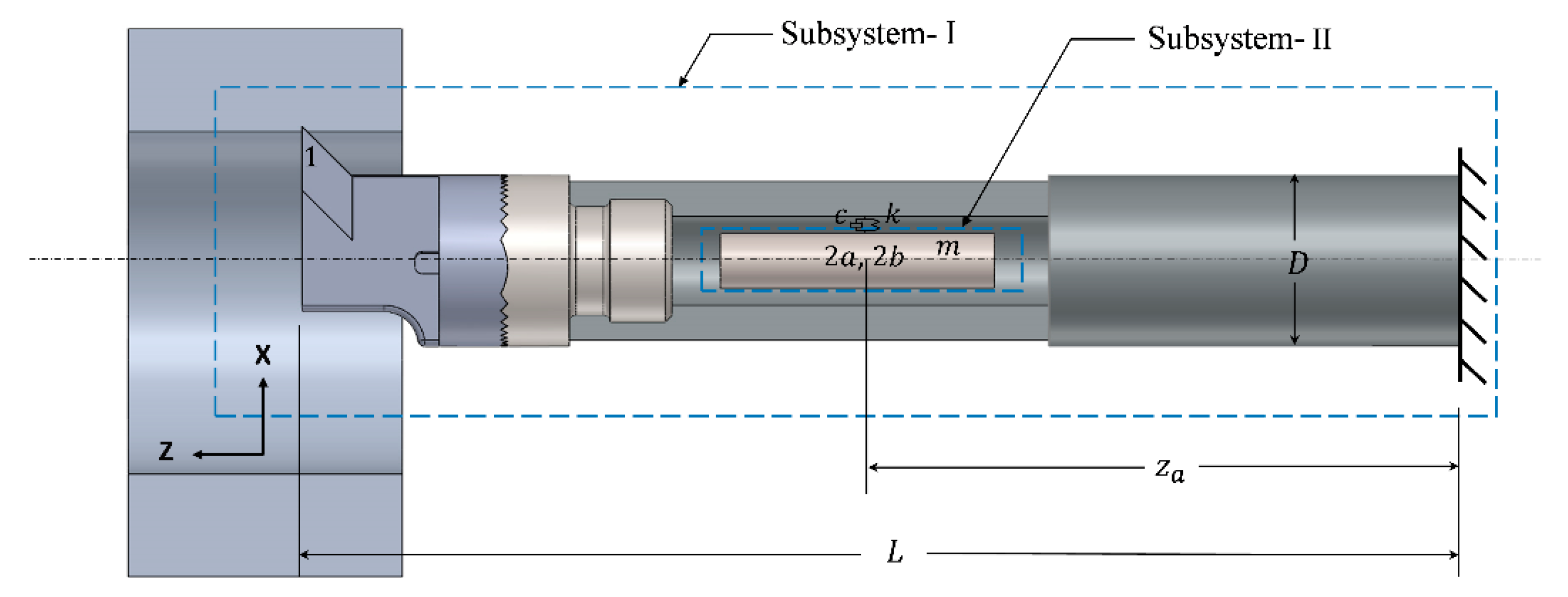
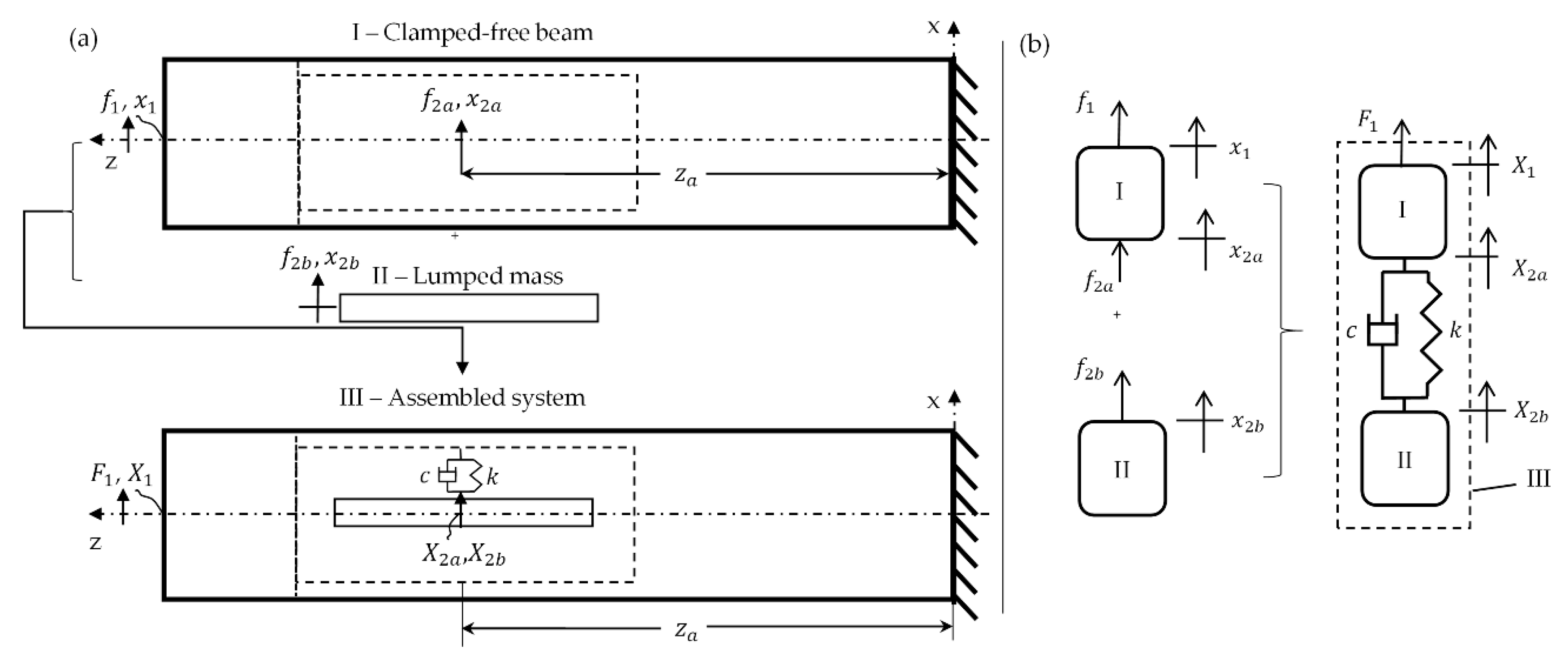
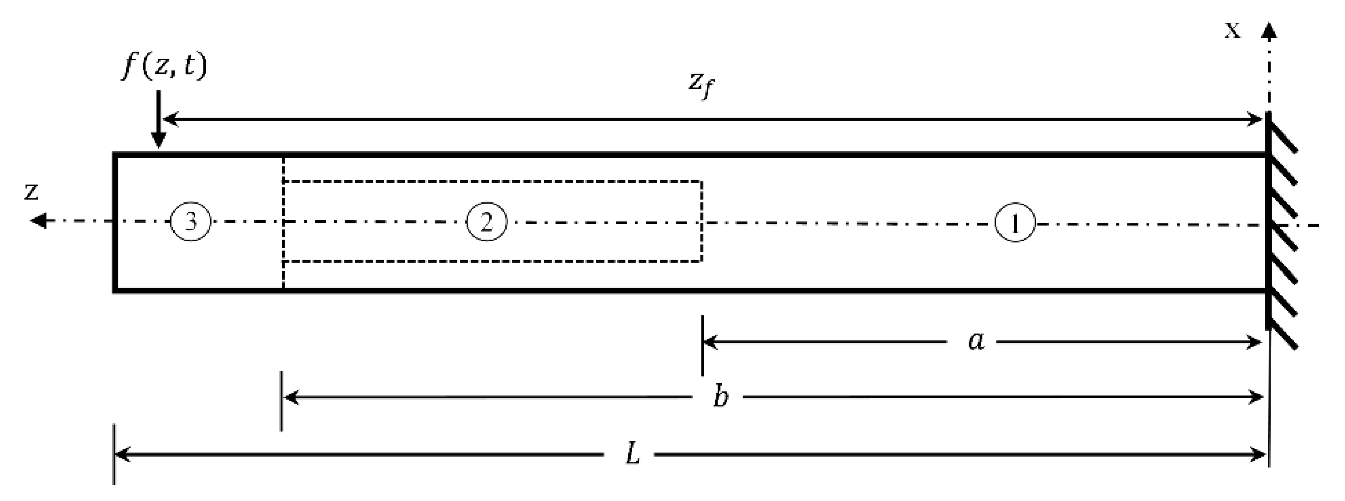
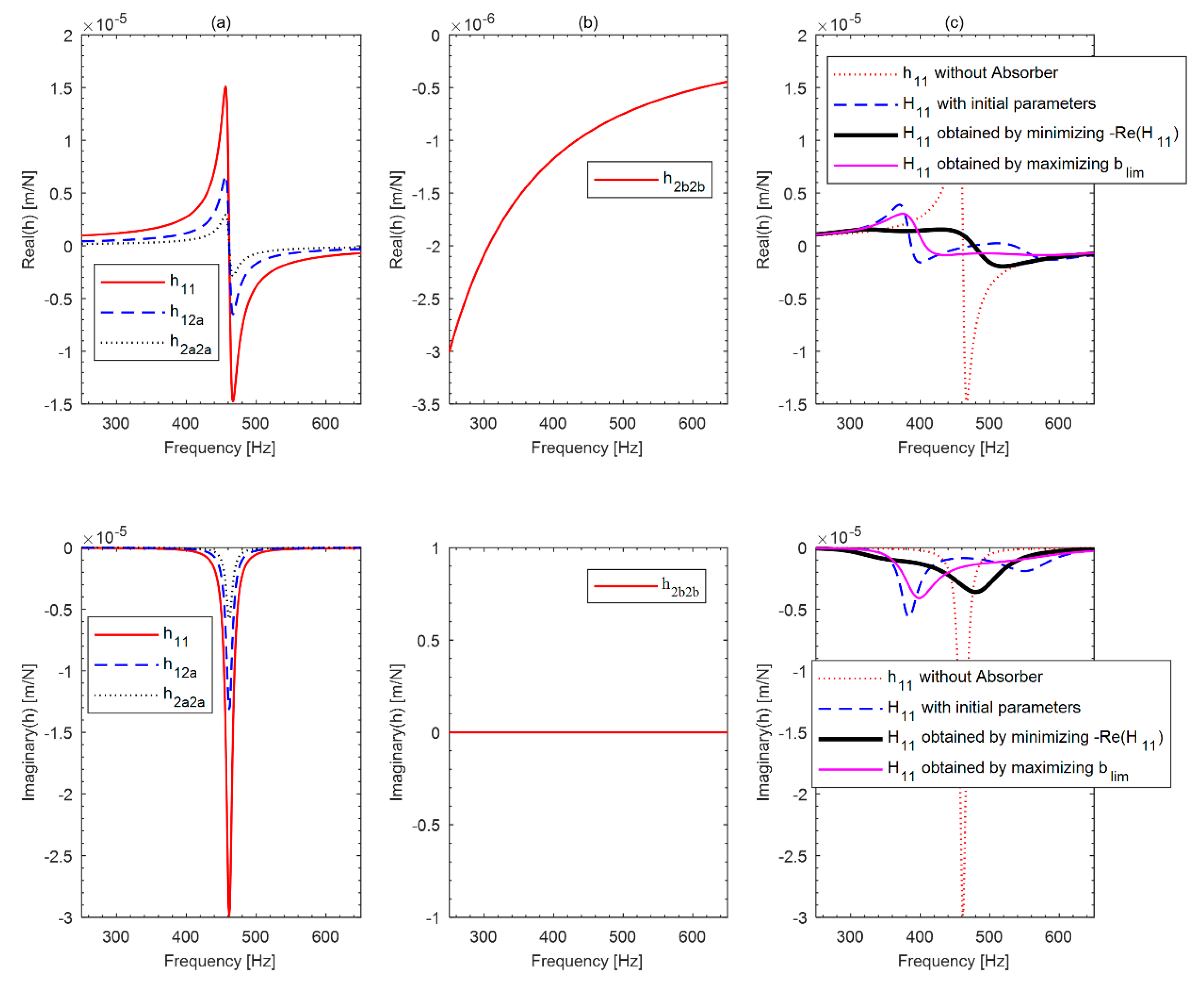
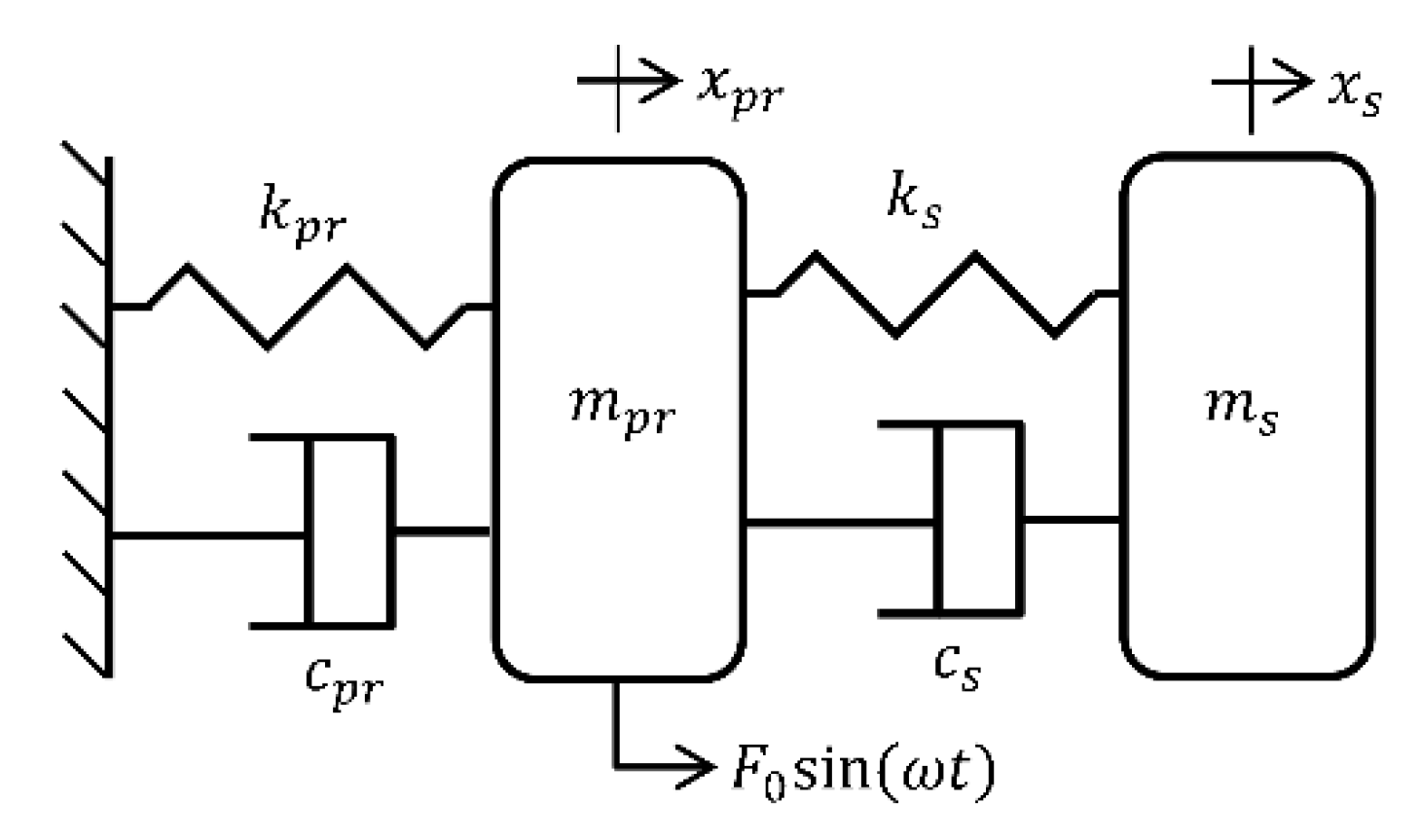
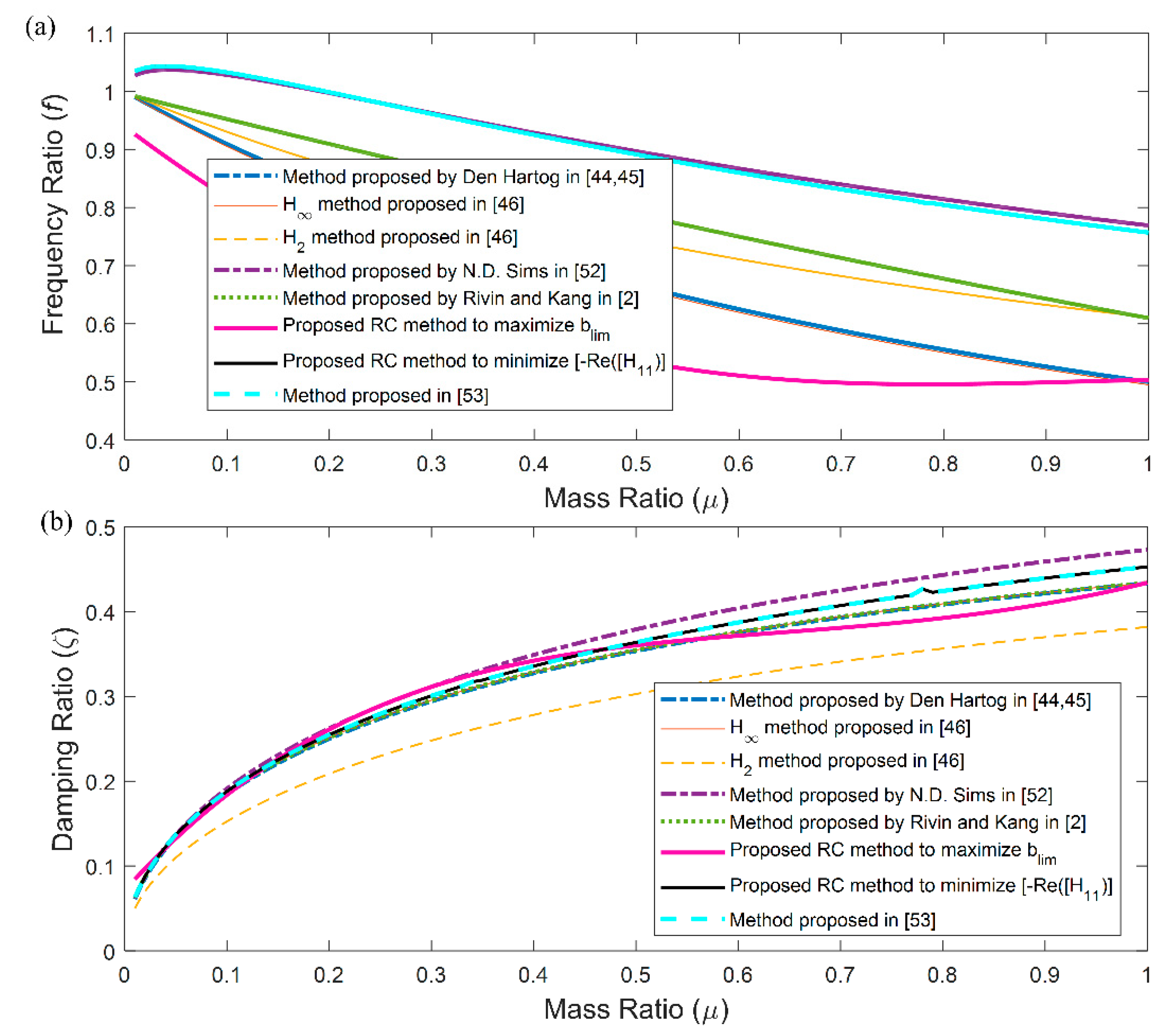
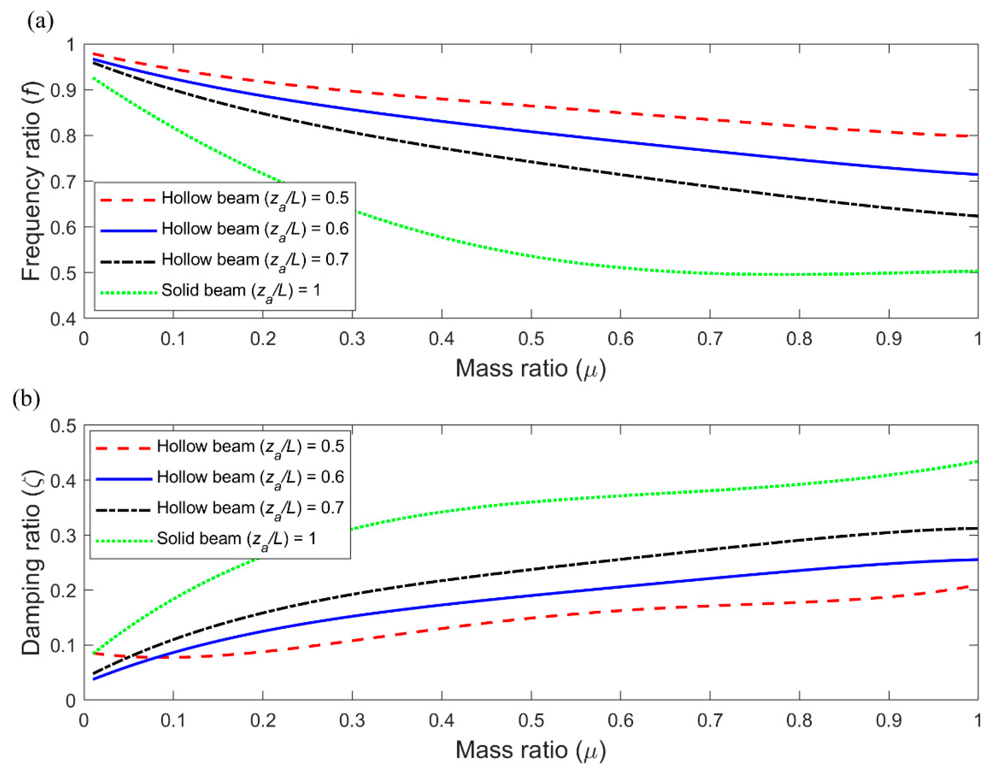
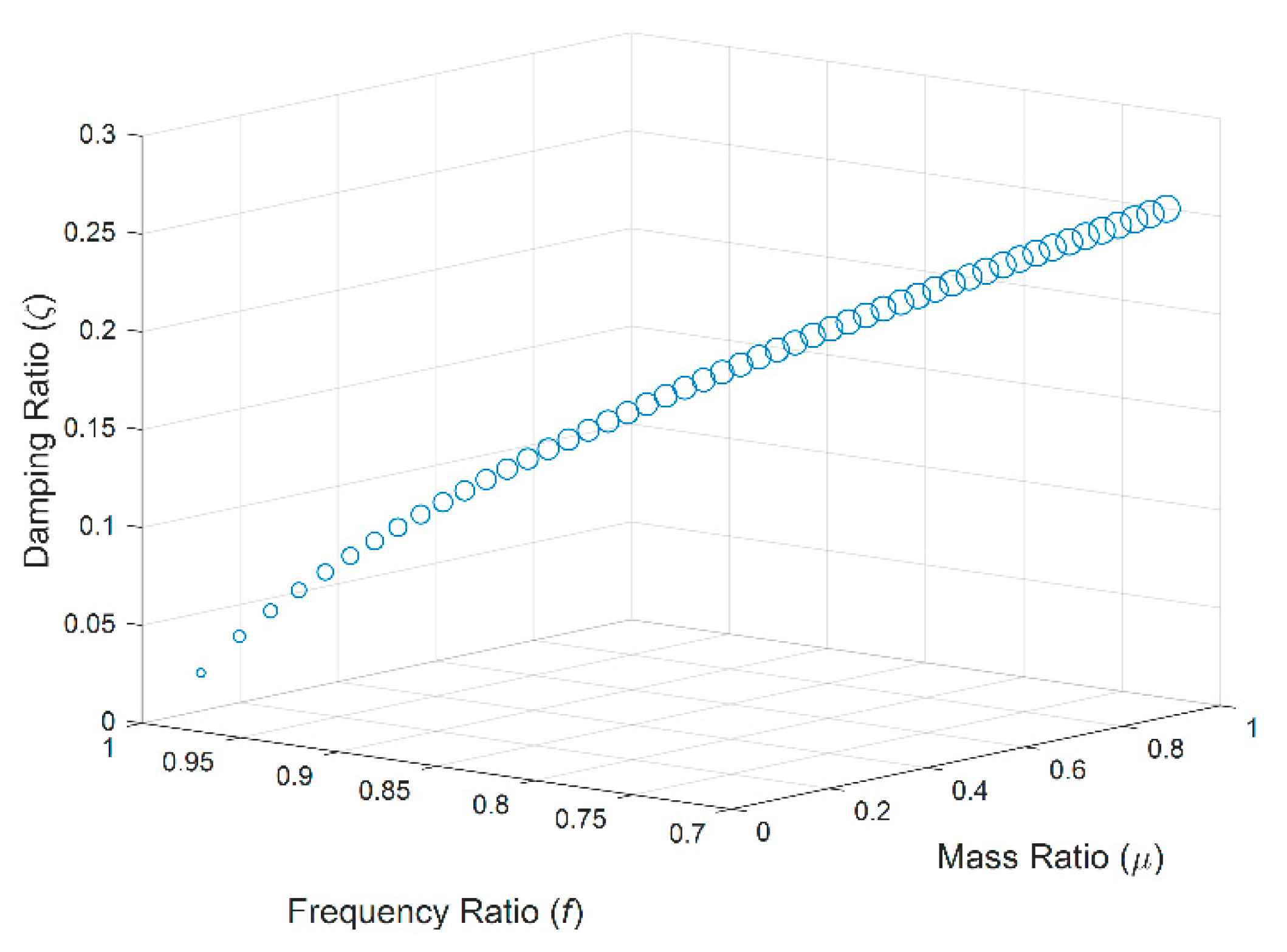
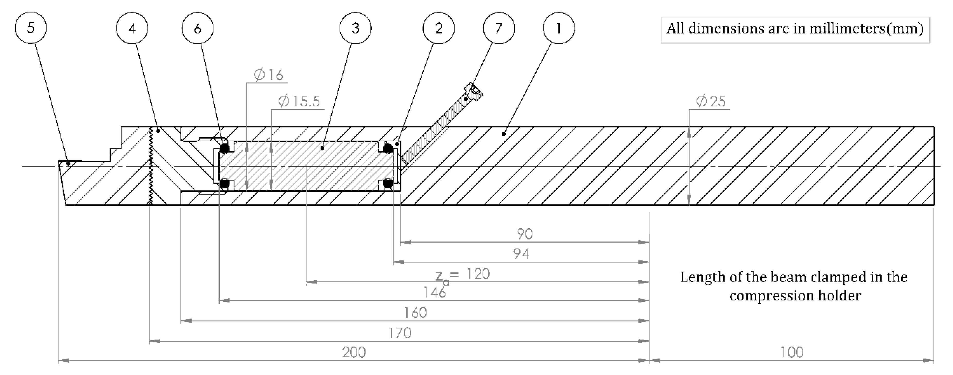
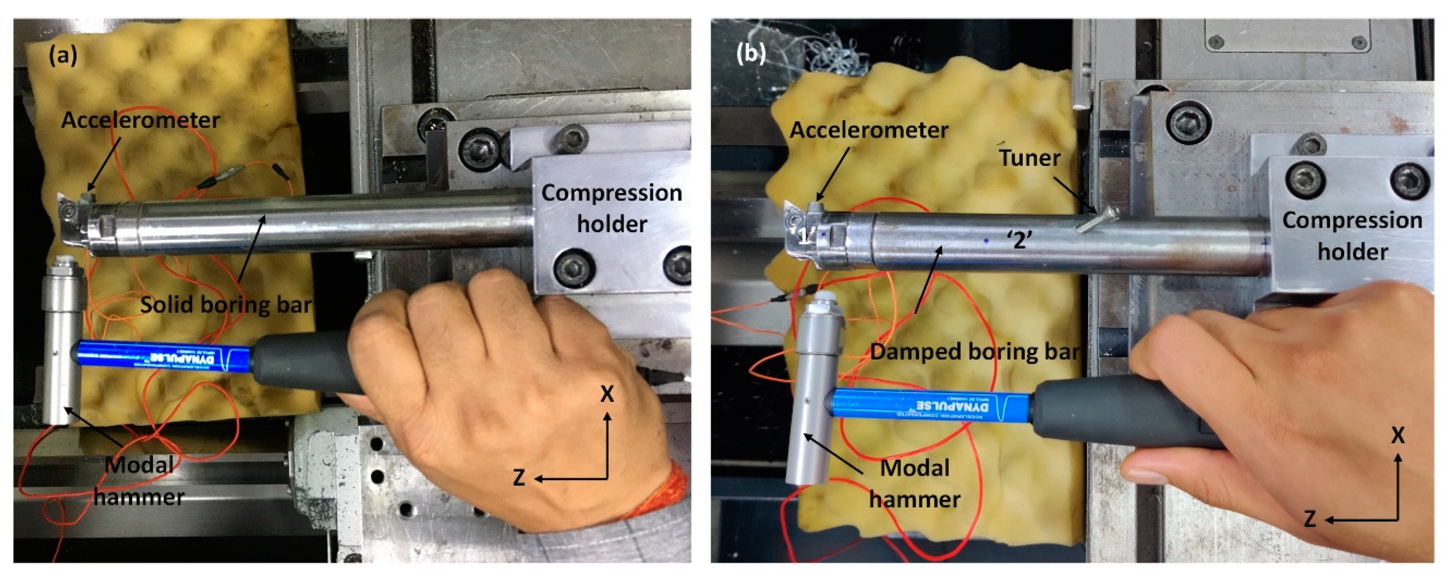
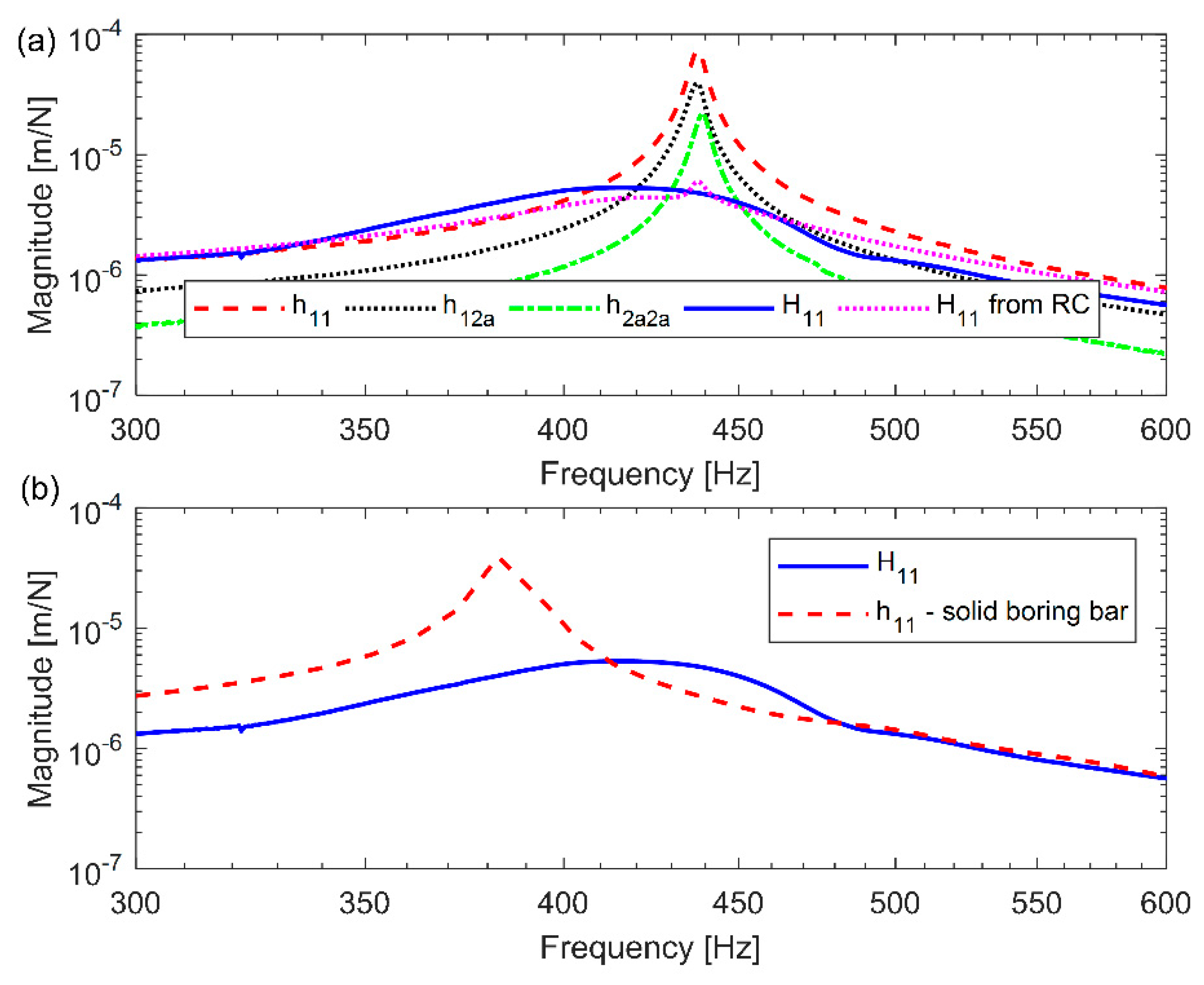
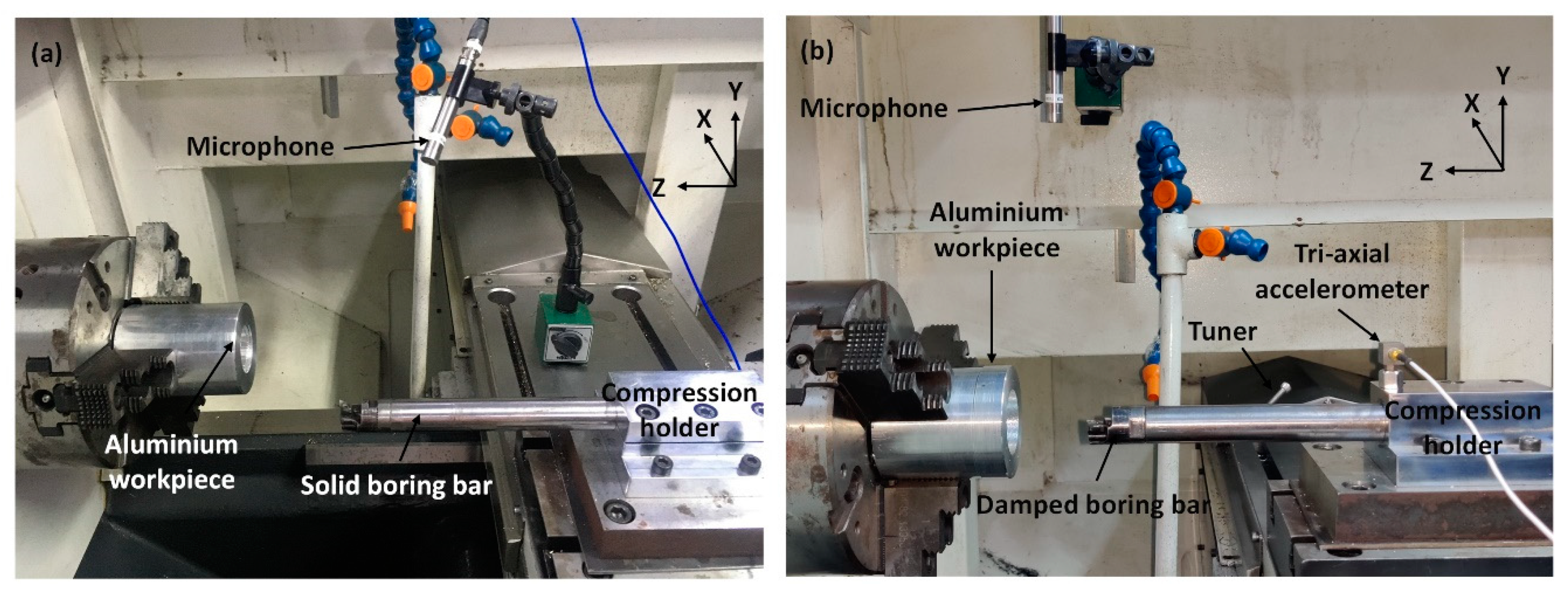
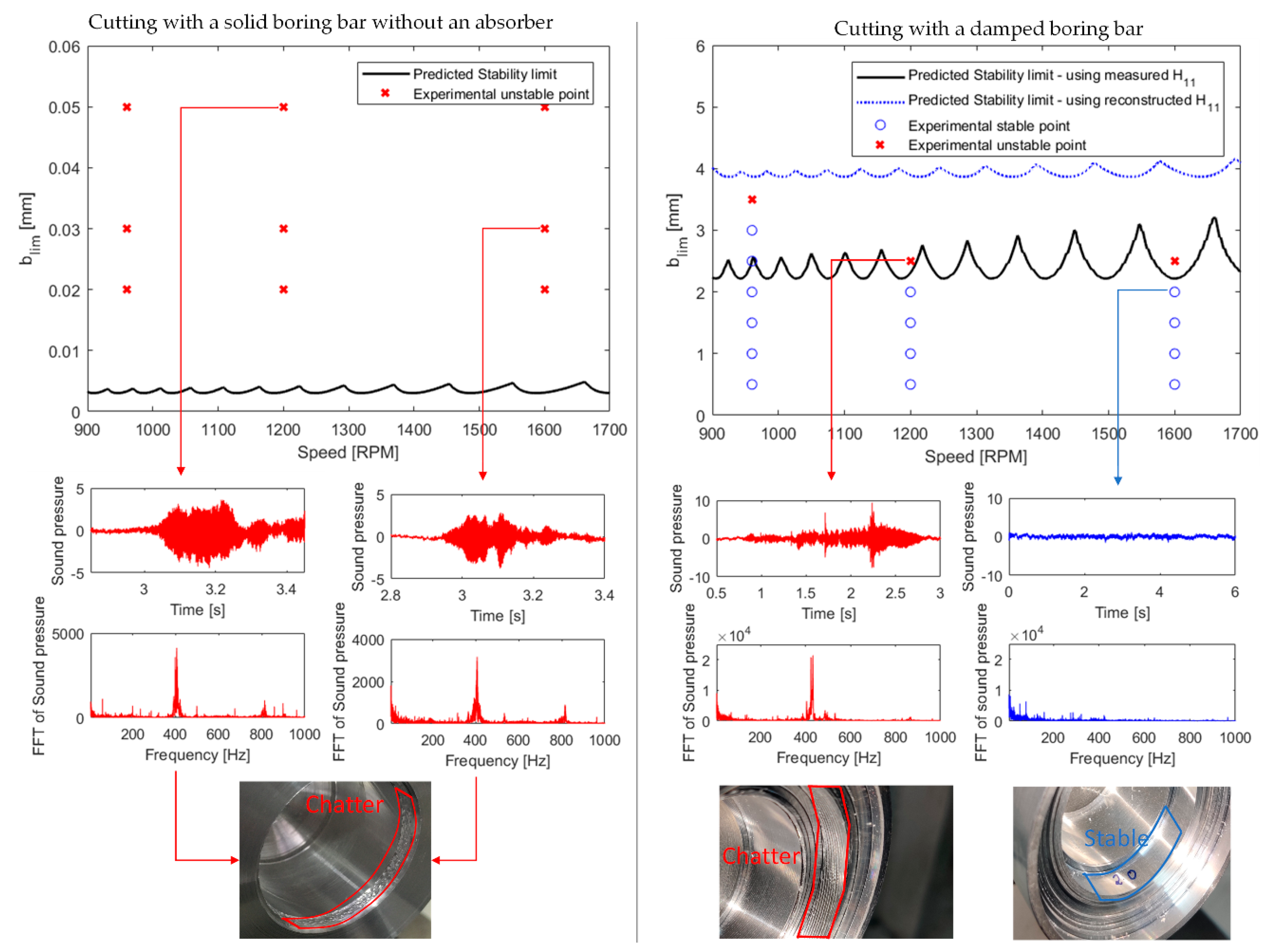
Table 2.
Comparison of absorber’s stiffness and damping parameters identified using an inverse receptance coupling approach and estimated using the proposed receptance coupling approach.
Table 2.
Comparison of absorber’s stiffness and damping parameters identified using an inverse receptance coupling approach and estimated using the proposed receptance coupling approach.
| Absorber’s Stiffness [N/m] | Absorber’s Damping [N-s/m] | Method of Estimation |
|---|---|---|
| 238.8 | Inverse receptance coupling approach | |
| 190.2 | Obtained by maximizing chatter-free |
© 2020 by the authors. Licensee MDPI, Basel, Switzerland. This article is an open access article distributed under the terms and conditions of the Creative Commons Attribution (CC BY) license (http://creativecommons.org/licenses/by/4.0/).
Share and Cite
MDPI and ACS Style
Yadav, A.; Talaviya, D.; Bansal, A.; Law, M. Design of Chatter-Resistant Damped Boring Bars Using a Receptance Coupling Approach. J. Manuf. Mater. Process. 2020, 4, 53. https://0-doi-org.brum.beds.ac.uk/10.3390/jmmp4020053
AMA Style
Yadav A, Talaviya D, Bansal A, Law M. Design of Chatter-Resistant Damped Boring Bars Using a Receptance Coupling Approach. Journal of Manufacturing and Materials Processing. 2020; 4(2):53. https://0-doi-org.brum.beds.ac.uk/10.3390/jmmp4020053
Chicago/Turabian StyleYadav, Ajay, Devangkumar Talaviya, Ankit Bansal, and Mohit Law. 2020. "Design of Chatter-Resistant Damped Boring Bars Using a Receptance Coupling Approach" Journal of Manufacturing and Materials Processing 4, no. 2: 53. https://0-doi-org.brum.beds.ac.uk/10.3390/jmmp4020053