1. Introduction
The consumption of aluminum alloys is growing in many industries, as they are lightweight and easy to recycle. This growth creates the need for better ways of welding aluminum alloys with satisfactory mechanical and metallurgical properties [
1]. Aluminum alloys welded with conventional fusion welding techniques exhibit the formation of brittle intermetallic compounds that usually cause severe intermetallic cracking [
2]. It is difficult or almost impossible to weld high-strength aluminum alloys with conventional fusion welding techniques. Hence, solid-state welding techniques, such as ultrasonic welding and friction stir welding, are better alternatives to welding aluminum alloys. Zhang et al. [
3] reported their research findings on the segregation and intermetallic precipitation of alloying elements at the material interface during the dissimilar ultrasonic welding of AA6111 and Ti6Al4V. Macwan et al. [
4] characterized the mechanical and microstructural properties of ultrasonic spot welds of a rare earth-containing ZEK100 magnesium alloy and AA5754.
Iwashita et al. [
5] and Fujimoto et al. [
6] documented a friction stir spot welding method for joining aluminum alloys for automotive applications. Friction Stir Spot Welding (FSSW) is a solid-state welding technique that is a variant of friction stir welding (FSW) invented by The Welding Institute in 1991 [
7]. Li et al. [
8] documented the current status and the research progress of Al-Cu FSSW in terms of weld tool features, mechanical and microstructural properties, and weld defects. Su et al. [
9] demonstrated FSSW of dissimilar AA5754 and a magnesium alloy. FSSW leaves behind a keyhole, which is a tool exit hole at the center of the spot weld. A keyhole causes stress concentrations that degrade the structural integrity of the assembly. Additionally, a keyhole is susceptible to corrosion, as its inner surfaces are hard to reach during painting. Therefore, refilling strategies for FSSW have been explored by numerous researchers, including Schilling and Dos Santos [
10] as well as Okada et al. [
11,
12].
Refill friction stir spot welding (RFSSW) is an emerging technology for joining aerospace aluminum alloys. Currently, aerospace industries use riveting to assemble aircraft components, as riveting bears well-established standards and specifications. Unlike riveting, RFSSW does not require any filler or foreign materials for joining and, hence, no additional weight is added to the assembly. RFSSW thermo-mechanically produces a molecular level bond between workpieces. There is no lack of fusion or material deterioration exhibited by RFSSW, as it does not involve major phase transitions during the welding process. Unlike FSSW, RFSSW produces a spot joint with a near-flush surface finish that is free from a key or exit hole. Schmal et al. [
13] explored the influences of the RFSSW process parameters on the joint formation and load-bearing capacities. Okada et al. [
11,
12] and Boldsaikhan et al. [
14] successfully demonstrated the use of RFSSW for joining high-strength aerospace aluminum alloys.
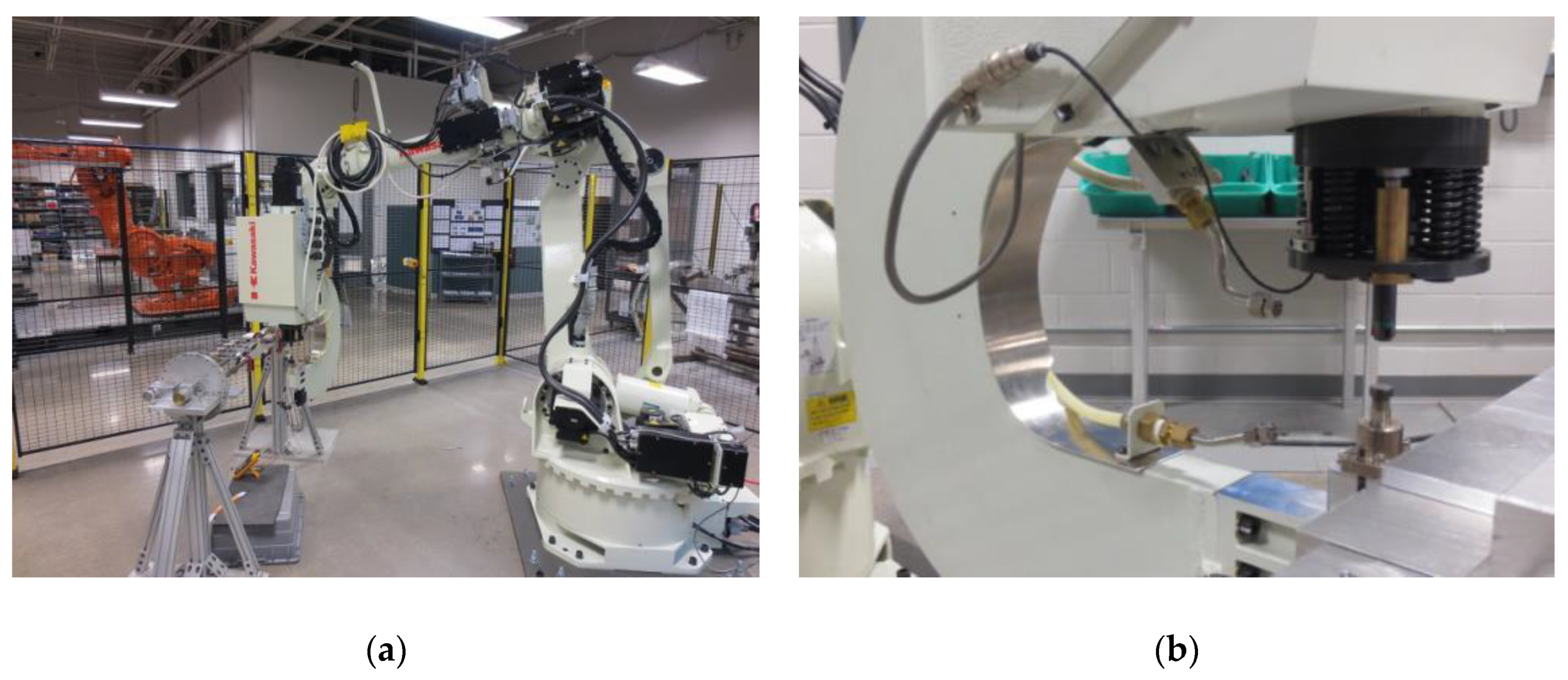
The robotic RFSSW system used in this study is shown in
Figure 1. This innovative robotic RFSSW system was designed and developed by Kawasaki Heavy Industries (KHI) [
11,
12]. The C-frame RFSSW end effector in
Figure 1b is equipped with a clamp tip, a backing anvil, and a retractable weld tool. The weld tool consists of a retractable probe enclosed in a cylindrical shoulder. The sizes of the refill spot weld are defined by the tool shoulder diameter and the tool plunge depth. During the RFSSW process, the weld tool goes through five different stages [
12,
15].
Stage 1: Stage 1 involves workpiece clamping and preheating. The workpieces are firmly clamped between the backing anvil and the clamp tip. Then, the rotating weld tool touches down and resides on the top surface of the workpiece for a certain time period to preheat the material via friction.
Stage 2: In this stage, the shoulder plunges into the workpiece and the probe retracts. The retraction of the probe opens a cavity to accommodate the material displaced by the plunging shoulder. When the targeted plunge depth is reached, the weld tool dwells in that position for a certain time period. The shoulder-plunging process requires a higher plunge force to stir a higher volume of material to achieve a stronger weld [
12,
15]. This study employed the shoulder-plunging process.
Stage 3: In the third stage, the rotating probe and the shoulder move in the reverse directions to re-inject the displaced material back into the weld chamber. Furthermore, to improve the flushness of the surface, the probe and the shoulder continue to move in the reverse directions until they slightly exceed their aligned position.
Stage 4: In Stage 4, the probe and the shoulder are aligned with each other right on the top surface of the workpiece to leave behind a near-flush surface finish.
Stage 5: In the fifth stage, the weld tool is removed.
The RFSSW process leaves behind three distinct weld zones in the workpiece, which are a heat-affected zone (HAZ), a Thermo-Mechanically-Affected Zone (TMAZ), and a weld nugget. HAZ is a region in the heat-treatable base metal that spans around the weld as its outermost shell. It is affected by the process heat but not the mechanical stirring. TMAZ is an interlayer shell between the HAZ and the weld nugget. It is affected by the process heat as well as the mechanical stirring involved in the weld nugget. The weld nugget is the core of the weld, where the tool forges and stirs the plasticized material together during the welding process. It experiences the greatest heat and plastic deformations that lead to significant grain refinement and re-precipitation. The size of the RFSSW weld nugget is defined by the outer diameter of the weld tool shoulder and its plunge depth. The metal grain size usually coarsens in TMAZ and HAZ during and after the welding process. However, the grain size becomes fine and equiaxed in the weld nugget due to grain refinement and re-precipitation involved in the weld nugget.
As RFSSW and FSSW are variants of FSW, they demonstrate similar weld properties. Fonda and Bingert [
16] investigated TMAZ and HAZ produced by FSW of AA2519 to determine their effects on the mechanical properties of the weld. A micrographic map revealed that the location of the fracture was at the boundary between TMAZ and HAZ, where the metal grains are coarser [
16]. According to Paglia and Buchheit [
17], the sensitization in HAZ of friction-stir-welded aluminum alloys is responsible for the corrosion susceptibility. Khodir and Shibayanagi [
18] studied the microstructure and the mechanical properties of friction-stir-welded dissimilar AA2024-T3 and AA7075-T6. They found that the hardness values of FSW increase with the increasing tool travel speed [
18]. Zhao et al. [
19], Arul et al. [
20], Freeney et al. [
21], and Tozaki et al. [
22] documented that FSSW produced higher weld strengths with the decreasing tool spindle speed. However, low spindle speeds may induce an insufficient heat input that leads to the formation of lack-of-consolidation defects and/or weld tool failures. Tran et al. [
23] demonstrated that the failure loads of friction stir spot welds grow with the increasing process time.
The literature on FSW, FSSW, and RFSSW mostly addresses relationships between the process parameters and the resultant weld properties. The novel contribution of this study is the investigation into the effects of the RFSSW design parameters, such as the spot weld spacing and the edge margin, on the mechanical properties of multi-spot-welded aircraft structures. A spot weld spacing refers to a center-to-center distance between two adjacent spot welds. An edge margin is an edge-to-center distance between the material edge and a refill spot weld. A refill spot weld usually starts to fail in TMAZ / HAZ, where the metal grains are coarser due to the thermo-mechanical processing of the welding process. Therefore, the extent of HAZ/TMAZ of the refill spot weld is critical to properly arranging the design parameters of RFSSW.
The aim of the study is to investigate the effects of the refill friction stir spot weld spacing and edge margin on mechanical properties of multi-spot-welded panels with an emphasis on aerospace applications. The study uses a baseline aerospace aluminum alloy, AA7075-T6, used in aircraft structures [
24]. A spot weld spacing (pitch) is a center-to-center distance between two adjacent spot welds in the same row. An edge margin (EM) is a center-to-edge distance between a spot weld and the material edge. The experimental strategy uses Design of Experiments (DoE) to characterize the failure loads of multi-spot-welded AA7075-T6 panels in terms of the spot weld spacing, the edge margin, and the spot weld HAZ. The multi-spot-welded panels are subjected to static lap-shear pull tests and Vickers microhardness tests to identify their failure loads and the spot weld HAZ patterns, respectively. The spot weld spacing (pitch) and the edge margin are studied in relation to the size of the HAZ. As mentioned earlier, the RFSSW process leaves behind a thermal “imprint” as HAZ in heat-treatable aluminum alloys.
The remaining sections of this article are organized as follows.
Section 2 presents the workpiece materials, experimental conditions, and research methods used in this study.
Section 3 contains the test results and a discussion of the analysis results.
Section 4 summarizes the conclusions supported by the research findings.
2. Materials and Methods
Sheet metals of bare 1.6 mm-thick AA7075-T6 were refill friction stir spot welded in a lap joint configuration to produce multi-spotwelded panels. AA7075-T6 is a baseline aerospace aluminum alloy used in aircraft structures [
24]. The properties of AA7075-T6 are shown in
Table 1. The RFSSW tool consists of a retractable probe with a diameter of 4 mm and a sleeve shoulder with an outer diameter of 7 mm. The RFSSW process employed the shoulder-plunging method. The outer diameter of the sleeve shoulder defines the diameter of the refill spot weld. The study used the following RFSSW process parameters to produce all the multi-spot-welded AA7075-T6 panels.
Plunge depth: 1.9 mm.
Probe speed: 4 mm/s.
Spindle speed: 1400 rpm.
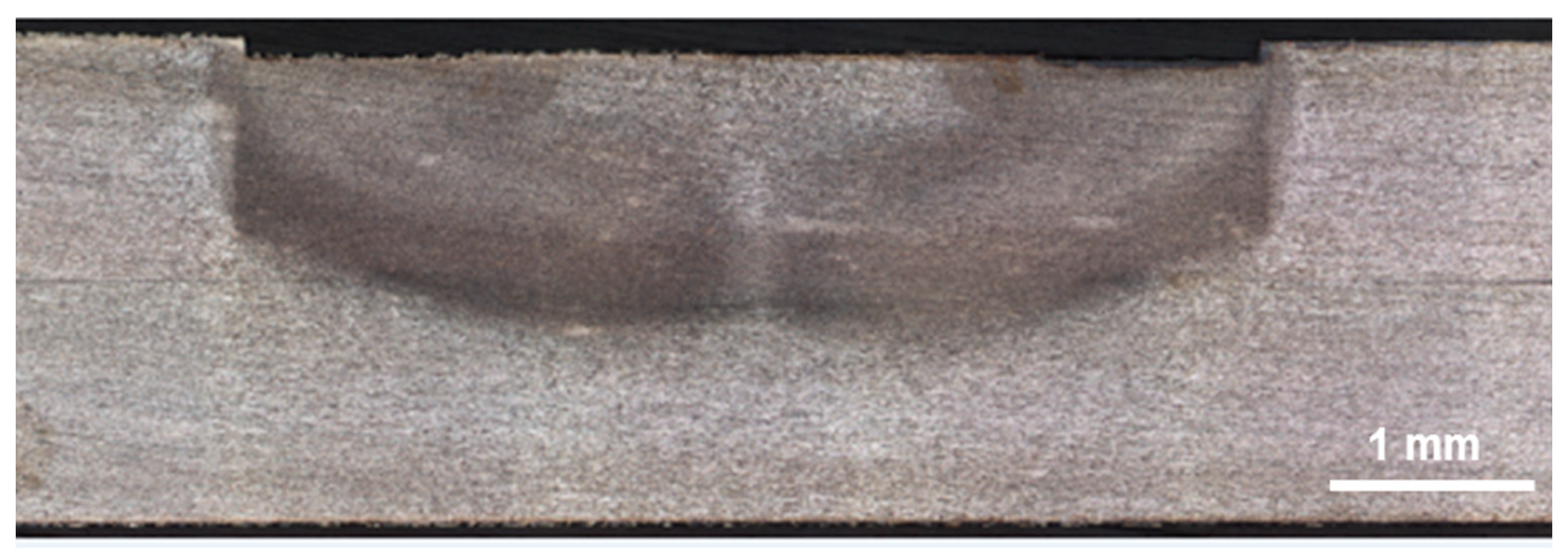
It is assumed that the HAZ geometry of a refill spot weld is radial. To identify the diameter of the HAZ, a single spot weld coupon was produced with bare 1.6 mm-thick AA7075-T6 sheets using the same RFSSW tool and the same process parameters.
Figure 2 depicts a cross-section image of the single spot weld coupon, where the top and bottom sheets are 1.6 mm-thick AA7075-T6 sheets.
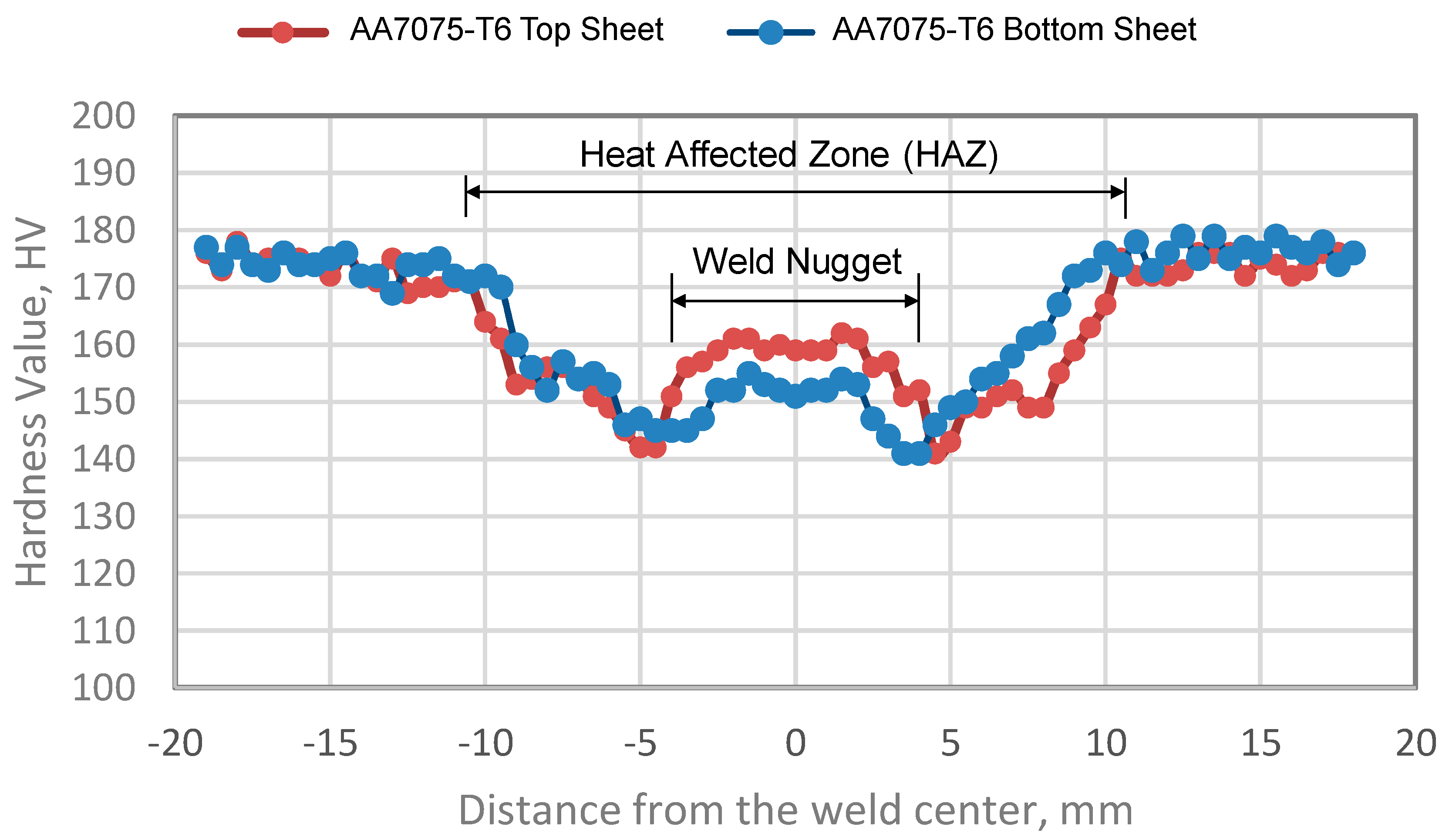
Figure 3 exhibits a cross-sectional microhardness map of the single spot weld coupon.
Figure 3 suggests that the diameter of HAZ is about 3 times the diameter of the refill spot weld. The diameter of the refill spot weld is 7 mm, which is the outer diameter of the tool shoulder.
The experimental method of this study was based on Design of Experiments (DoE). A 3
2 full factorial design was employed with two design factors, which are the spot weld spacing (pitch) and the edge margin (EM). The DoE response variable was the ultimate lap-shear load (the failure load) of a refill spot weld. A spot weld spacing (pitch) is a center-to-center distance between two adjacent spot welds within the same row. An edge margin is a center-to-edge distance between a spot weld and the material edge. The 3
2 full factorial design consists of nine DoE runs with the configurations listed in
Table 2. Nine DoE runs produced nine 9-spot-welded panels, whereas the pitch and the edge margin were systematically varied according to
Table 2. D (=7 mm) is the spot weld diameter. The edge margin was varied between 1D, 1.5D, and 2D. The pitch (the spot weld spacing) was varied between 2D, 3D, and 4D. These variations were studied in relation to the size of the HAZ.
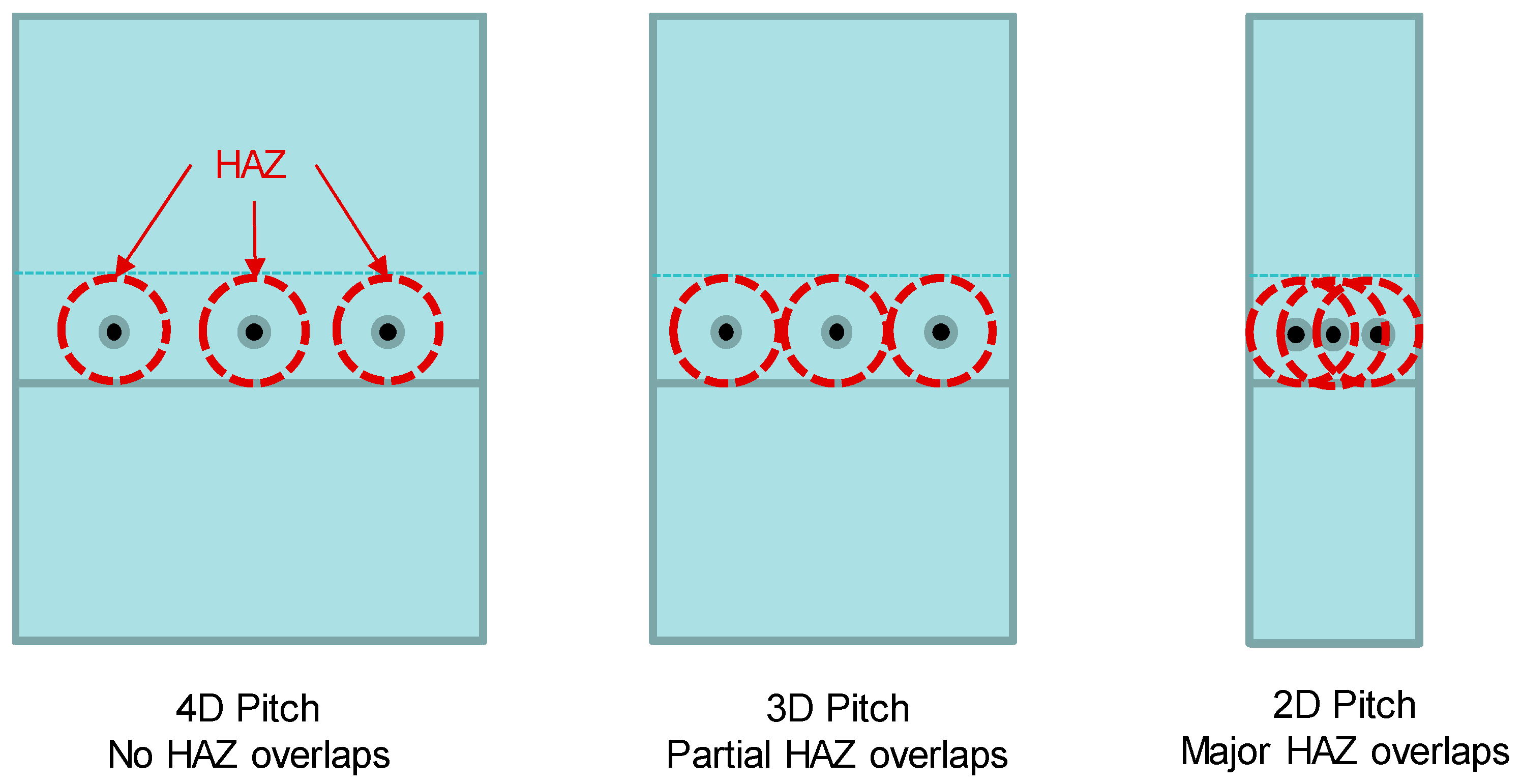
It is assumed that the HAZs of the 9-spot-welded panels should look similar to the HAZ in
Figure 3. With that being said, the 1D-pitch allows the HAZs of adjacent spot welds to overlap, as the diameter of the HAZ is about 3D. The 2D-pitch allows the HAZs of adjacent spot welds to barely touch each other. The 4D-pitch allows no HAZ overlaps. The spot weld HAZs and the spot weld spacings are illustrated in
Figure 4.
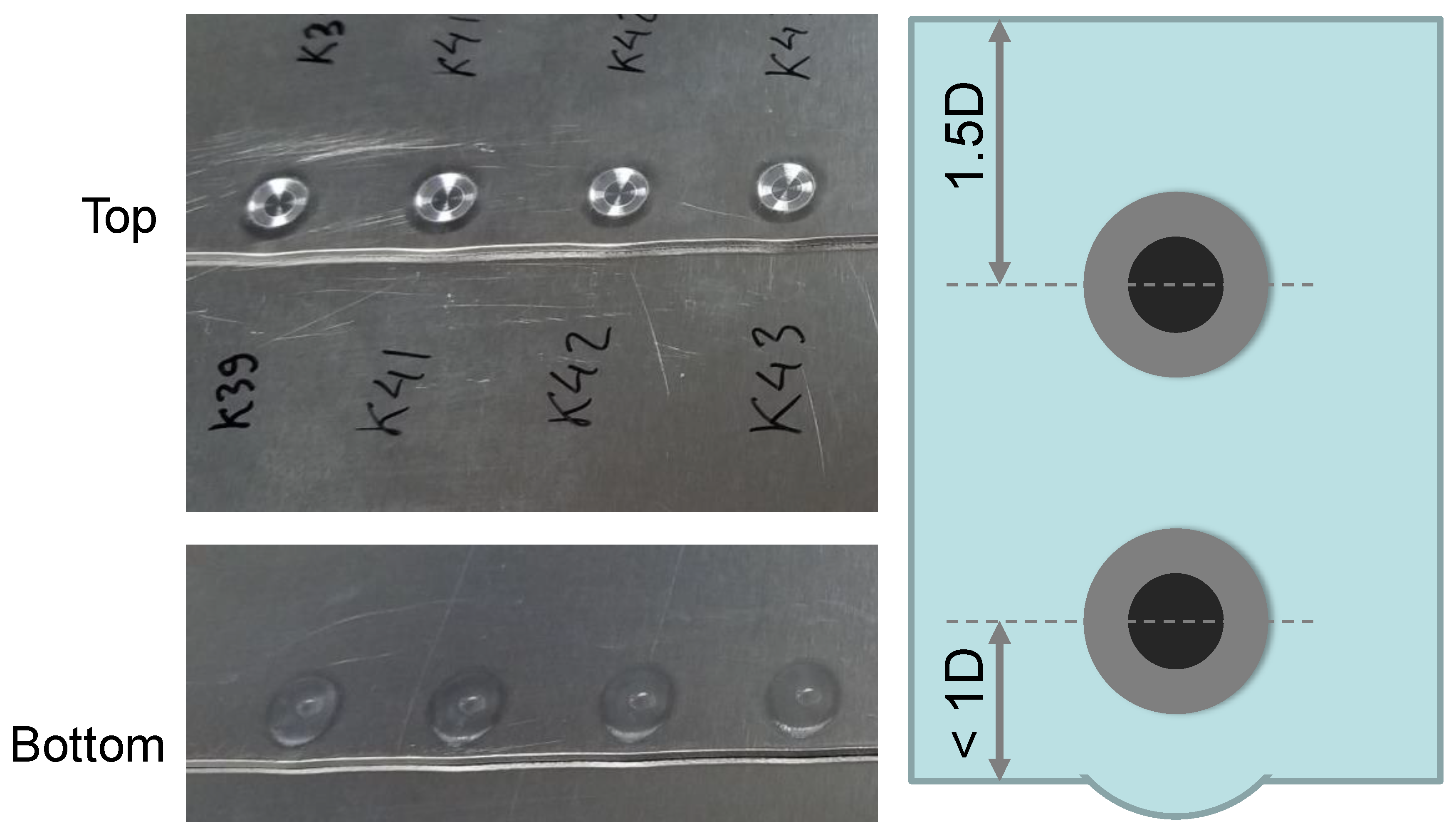
The 1D edge margin puts the workpiece edge inside the HAZ. The 1.5D edge margin puts the workpiece edge on the edge of the HAZ. The 2D edge margin puts the workpiece edge outside of the HAZ. The spot weld HAZs and the edge margins are illustrated in
Figure 5.
Sheets of metal were welded in a lap joint configuration, as specified in
Figure 6. Each welded panel had nine spot welds. The spot welds were numbered from left to right, as shown in
Figure 6. The 1-9-5-3-7-2-8-4-6 welding sequence was used for producing every welded panel. During the welding process, in order to avoid heat accumulation in the weld tool and the workpieces the weld tool was cooled down with compressed air for at least 90 s after every weld run. This 90 s delay between two successive weld runs was enough for bringing the tool temperature and the workpiece temperature down to their normal levels at room temperature. Therefore, it was assumed that HAZs of refill spot welds in a 9-spot-welded panel should look similar to the HAZ in
Figure 3.
After producing all the welded panels, they were naturally aged for at least two weeks. After natural aging, three single-spot-welded coupons including Spot Weld 3, Spot Weld 4, and Spot Weld 5 were extracted from each panel according to
Figure 6. The width of a single-spot-welded coupon was the spot weld spacing. Unguided static lap-shear pull tests were carried out on the single-spot-welded coupons to identify their ultimate lap-shear loads (the failure loads). The pull rate of the static test was 1.27 mm/min.
In addition to the single-spot-welded coupons, Spot Weld 6 and Spot Weld 7 were extracted from each panel as two-spot-welded specimens for cross-sectional microhardness measurements according to
Figure 6.
Figure 7 depicts the microhardness measurement lines of the cross-section specimen. The microhardness values were taken from the midplane lines of the top sheet and the bottom sheet of the cross-section specimen. A diamond indenter with a 0.5 kg load was used for Vickers hardness measurements.
Spot Weld 1 and Spot Weld 9 in
Figure 6 have only one neighboring spot each, but the rest of the spots have two symmetric neighboring spots each. Hence, the thermal “imprints” of Spot Weld 1 and Spot Weld 9 can be asymmetric. Therefore, Spot Weld 1 and Spot Weld 9 were excluded from this study so that they can be studied in the future work.
3. Results and Discussion
The DoE runs produced nine nine-spot-welded panels with systematically varied spot weld spacings and edge margins.
Figure 8 depicts some of the welded panels. All the welded panels were naturally aged for at least two weeks. After natural aging, single-spot coupons and two-spot specimens were extracted from every welded panel according to the cut plan shown in
Figure 6. Each DoE run had three single-spot coupons and one two-spot specimen. Static lap-shear pull tests were carried out on the single-spot coupons to identify their failure loads as the DoE response. Vickers microhardness tests were carried out on the two-spot specimens to identify their HAZ patterns.
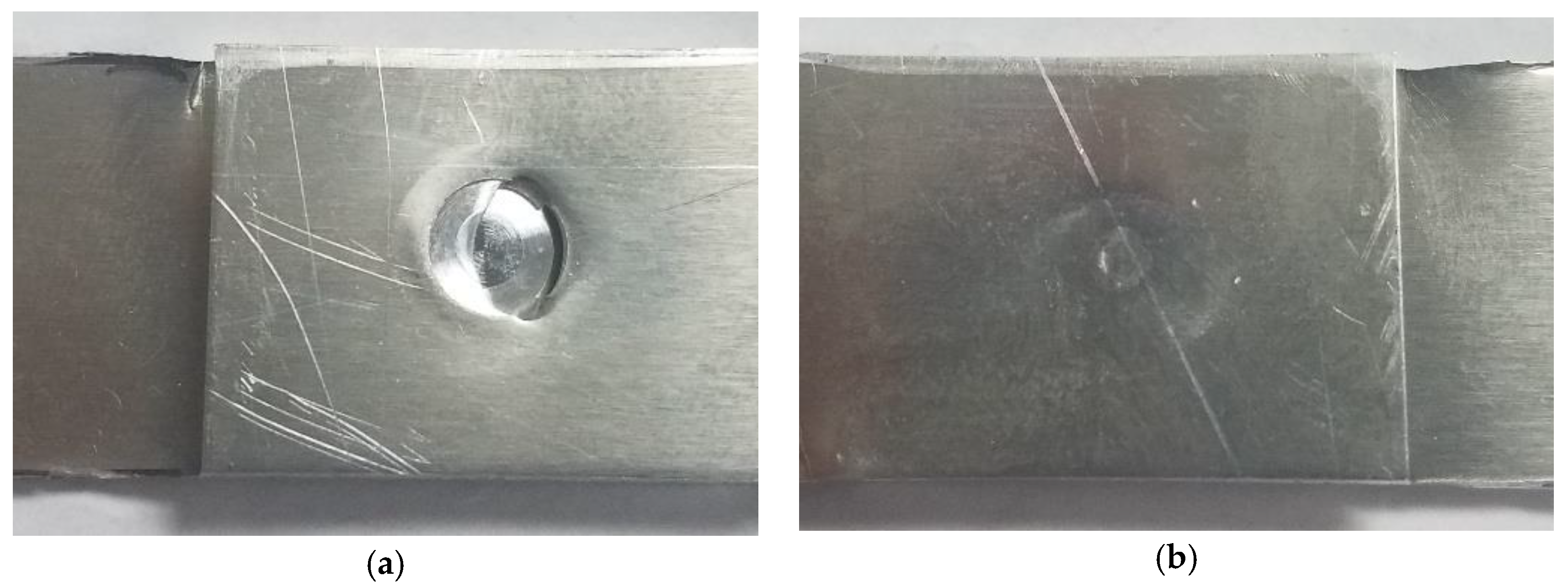
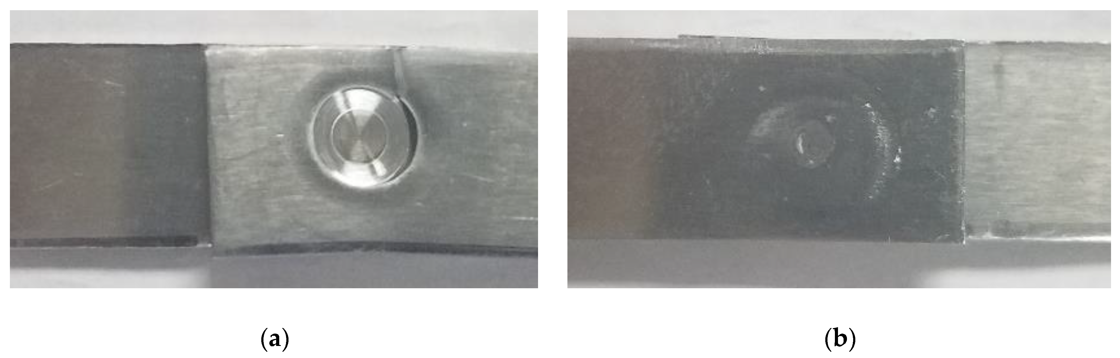
The thermo-mechanical processing of RFSSW produced edge swelling and noticeable dents in the weld crowns of the 1D-edge-margin panels, where D (=7 mm) is the spot weld diameter.
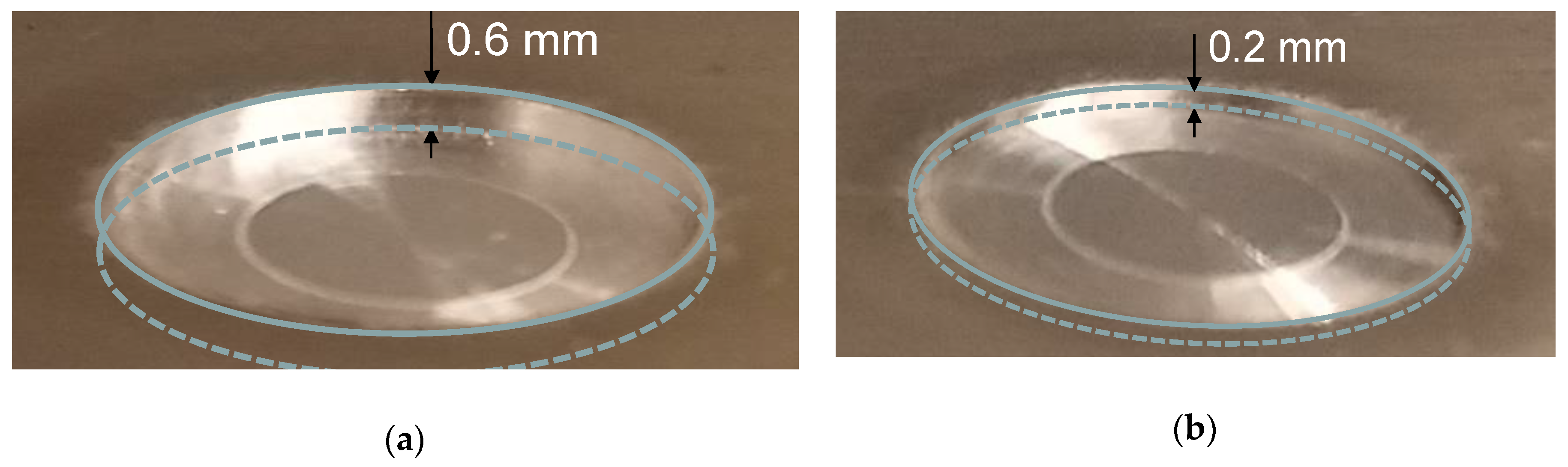
Figure 9 depicts the edge swelling of the 1D edge margin (EM). None of the panels with 1.5D EM and 2D EM exhibited edge swelling. Edge swelling was observed when the workpiece edge was exposed to the heat-affected zone (HAZ) during the welding process. Furthermore, edge swelling caused a noticeable dent in the weld crown, as depicted in
Figure 10. The panels with 1D EM exhibited 0.6 mm-deep dents in the weld crowns. However, the panels with 1.5D EM and 2D EM exhibited 0.2 mm-deep dents in the weld crowns.
Researchers [
9,
25,
26,
27] explain possible causes of the mechanical failures of friction stir spot welds under external loads. Su et al. [
9] observed that the energy input of the welding process influences the failure mode of the friction stir spot weld. Badarinarayan et al. [
25] documented that factors such as the stress distributions, material properties, and joint geometry determined the crack initiation and propagation in friction stir spot-welded assemblies. Mitlin et al. [
26] studied friction stir spot-welded aluminum alloys and found that the tool plunge depth has a significant effect on the failure mode of the spot weld.
In this study, during the unguided static lap-shear pull tests single spot-welded coupons demonstrated rotational deformation [
27] due to the asymmetric pull loads applied to the top and bottom sheets. The pull rate was 1.27 mm/min. The failure load was measured in the pull load direction. Single-spot-welded coupons demonstrated different mechanical failures during the unguided static lap-shear pull tests. The spot weld failures observed in this study were as follows.
The nugget pullout (NP) failure involves the weld nugget that is pulled out of the parent metal [
27]. Such failures usually occur in TMAZ/HAZ around the weld nugget, where the metal grain is coarser. A metal region with a coarser grain demonstrates a weaker mechanical strength.
The top sheet breakdown (TSB) failure is a through-thickness transverse crack that occurs across the top sheet [
27]. The failure originates in TMAZ/HAZ and propagates into the parent metal.
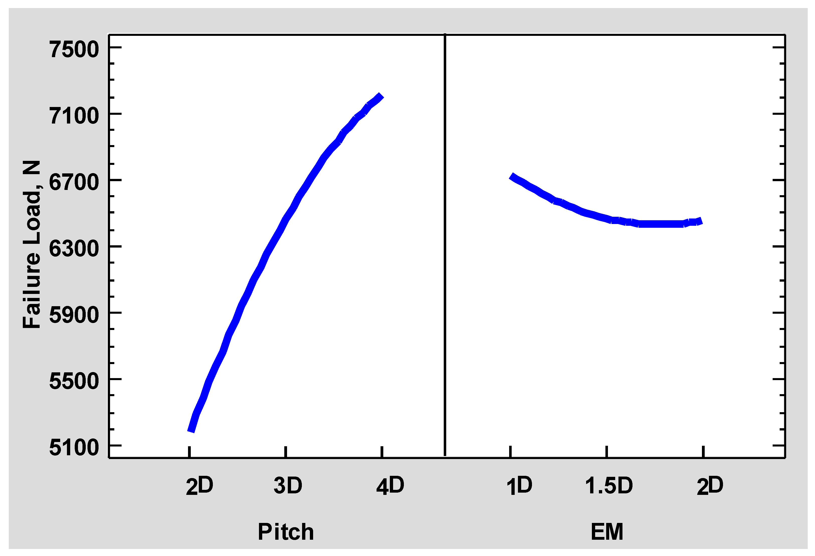
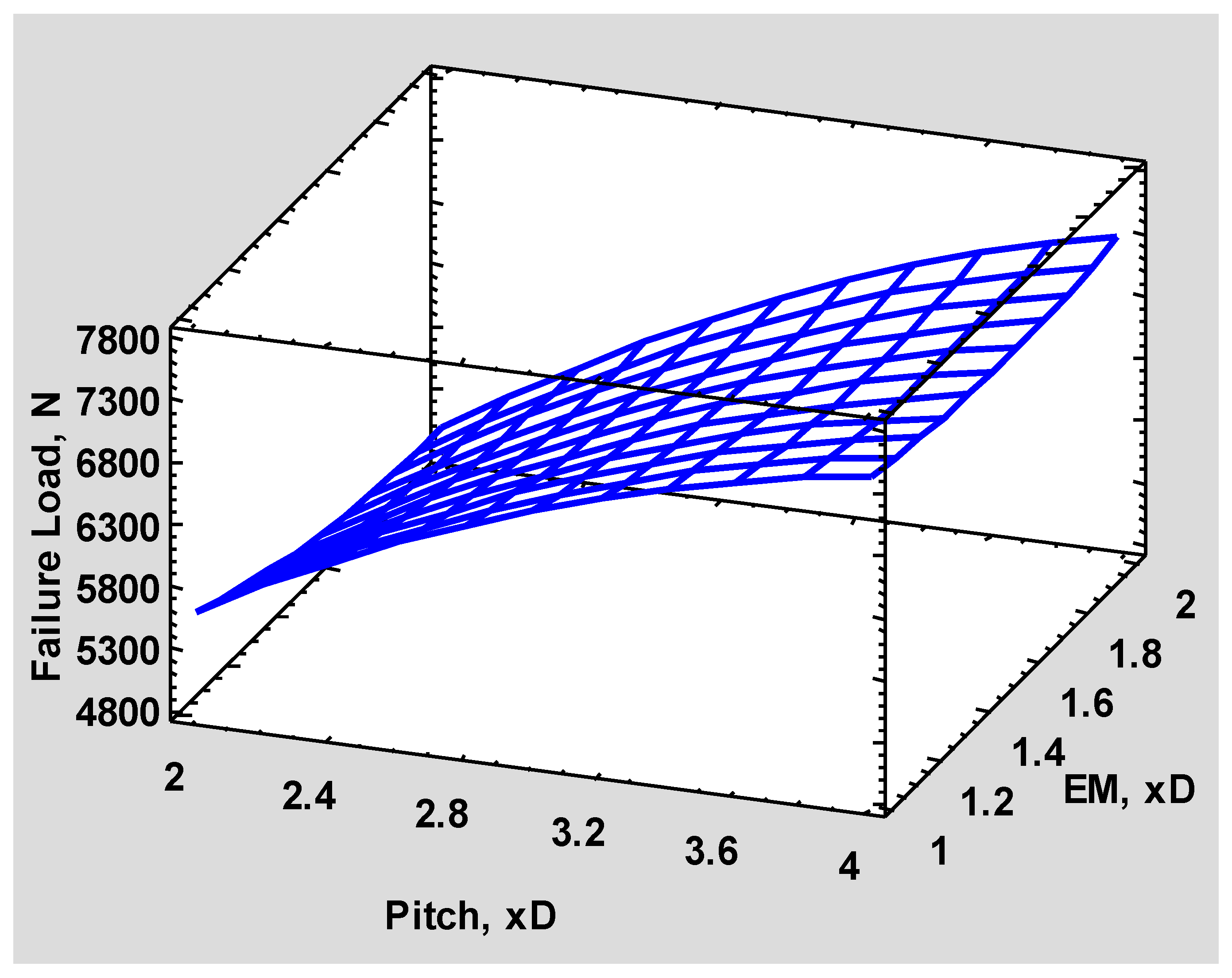
Figure 11 displays the DoE main effects plot and
Figure 12 displays the DoE response surface for the failure load. Each DoE run produced three coupon repetitions. All the coupons, except the coupons of DoE Run 2 and DoE Run 3, demonstrated nugget pullouts during the unguided static lap-shear pull tests.
Figure 13 depicts a nugget pullout failure. The coupons of DoE Run 2 and DoE Run 3 demonstrated top sheet breakdown failures during the mechanical tests.
Figure 14 depicts a top sheet breakdown failure. The failure loads of the DoE coupons were used as the DoE response. A response surface analysis [
28] was performed with the use of the Statgraphic
® software. The statistics of the response surface analysis are as follows.
The R-squared statistic of 94.5595% indicates that the response surface as fitted explains 94.5595% of the variability in the failure load. The standard error of the estimate shows the standard deviation of the residuals to be 244.139 N. The mean absolute error (MAE) of 169.568 N is the average value of the residuals. A p-value of 0.002 implies that the estimated response surface is statistically significant, as it is less than 0.05.
Unlike the 1.5D-EM panels and the 2D-EM panels, the 1D-EM panels produced edge swelling and surface dents in the weld crown during the welding process. In
Figure 11, the edge margin exhibits an insignificant effect on the failure load, as the material edge was transverse to the loading direction. If the material edge is parallel to the loading direction, it is intuitive to assume that larger side edge margins would offer a better strength, which could be a good topic for the future work. In addition, the main effects plotted in
Figure 11 suggest that the panels with larger spot weld spacings were stronger than the panels with smaller spot weld spacings. Perhaps a smaller spot weld spacing induces a higher heat input, as a higher or excess heat input usually degrades metal properties. Overall, the spot weld spacing (pitch) had an inverse relationship with the failure load of the multi-spot-welded panel.
During the welding process, in order to avoid heat accumulation in the weld tool and the workpieces, the weld tool was cooled down with compressed air for at least 90 s after every weld run. This 90 s delay between two successive weld runs was enough to bring the tool temperature and the workpiece temperature down to their normal levels at room temperature. Therefore, it was assumed that the HAZs of refill spot welds in a nine-spot-welded panel should look similar to the HAZ in
Figure 3. These findings can be verified with cross-sectional microhardness maps.
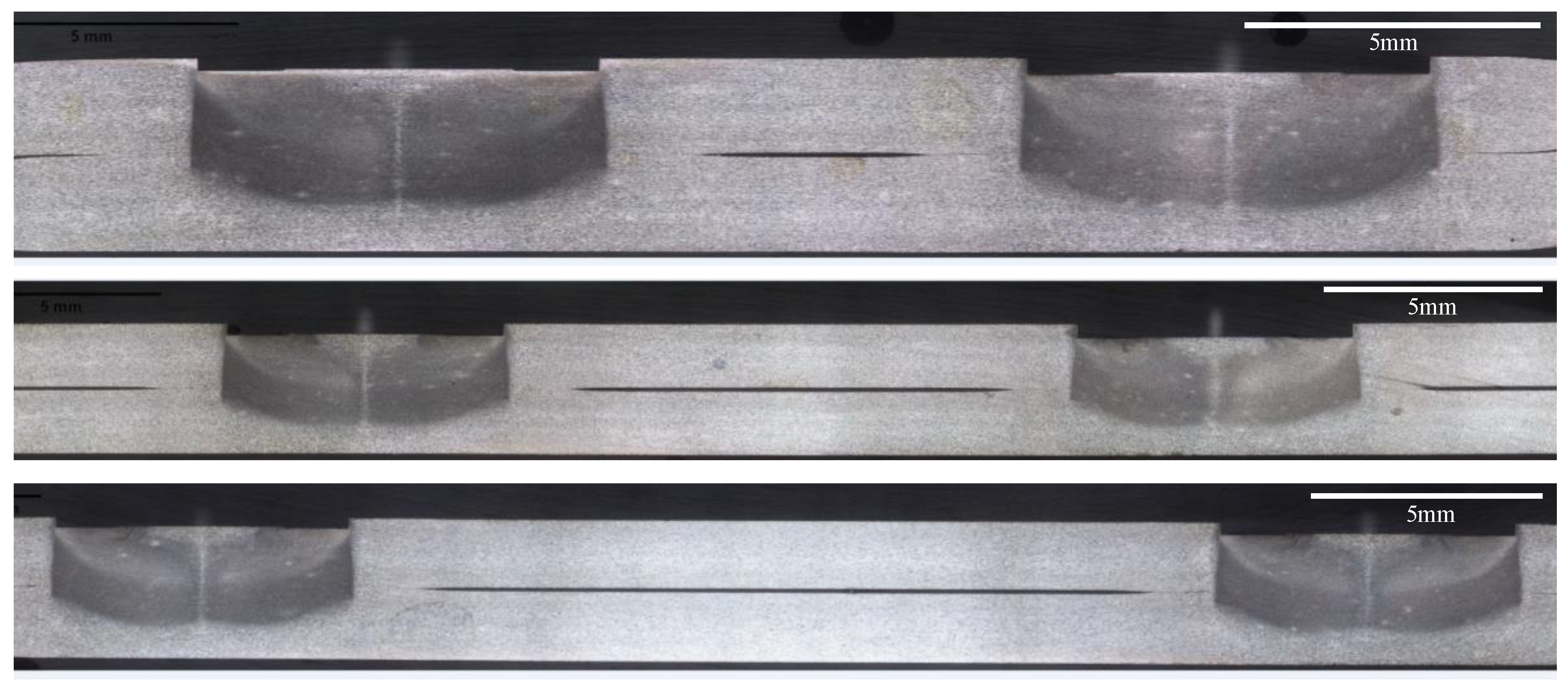
Figure 15 displays two-spot cross-section specimens extracted from nine-spot-welded panels according to the cut plan in
Figure 6. The cross-section specimens were polished and then etched with a chemical reagent. The hardness values of a cross-section specimen were measured along the midplane lines of the top sheet and the bottom sheet according to
Figure 7. The measurement line indents were spaced 0.5 mm apart.
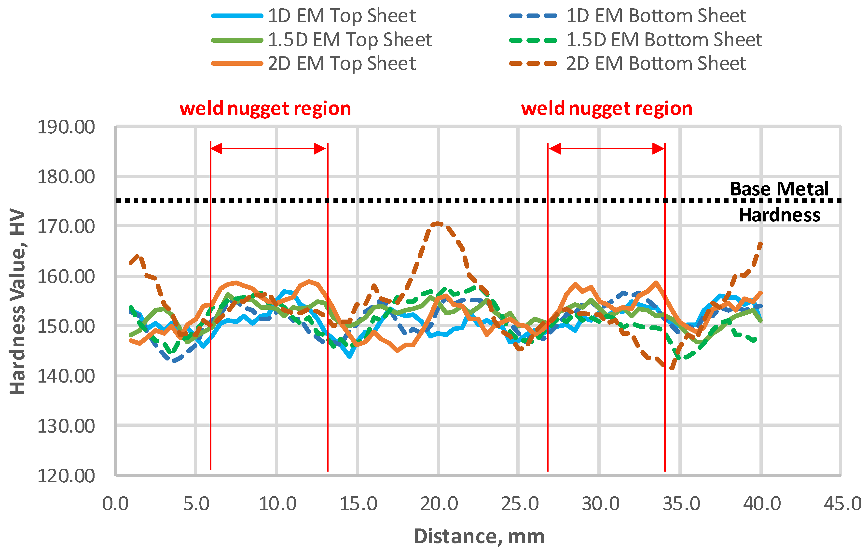
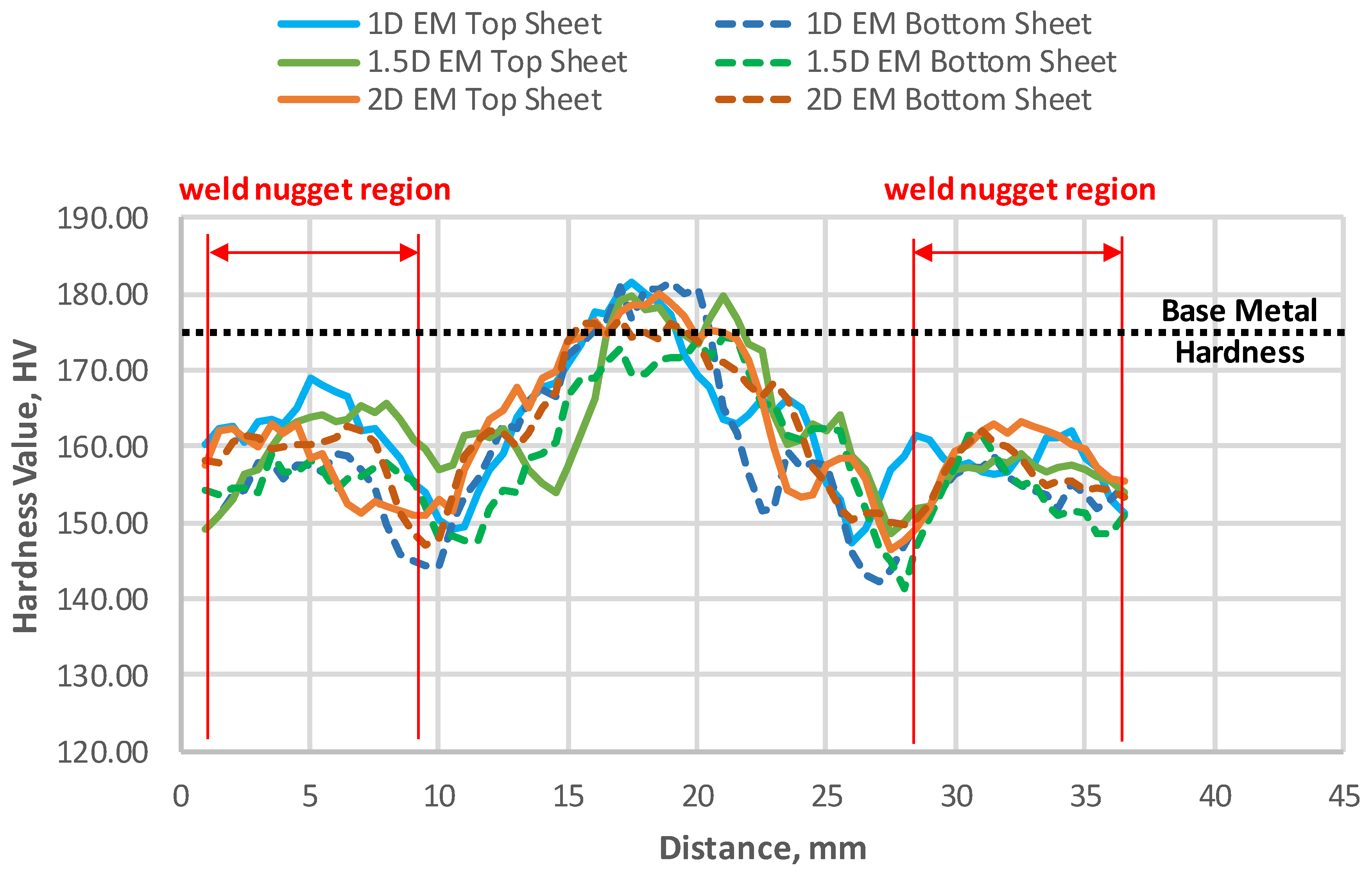
Figure 16,
Figure 17 and
Figure 18 display the microhardness maps of the cross-section specimens.
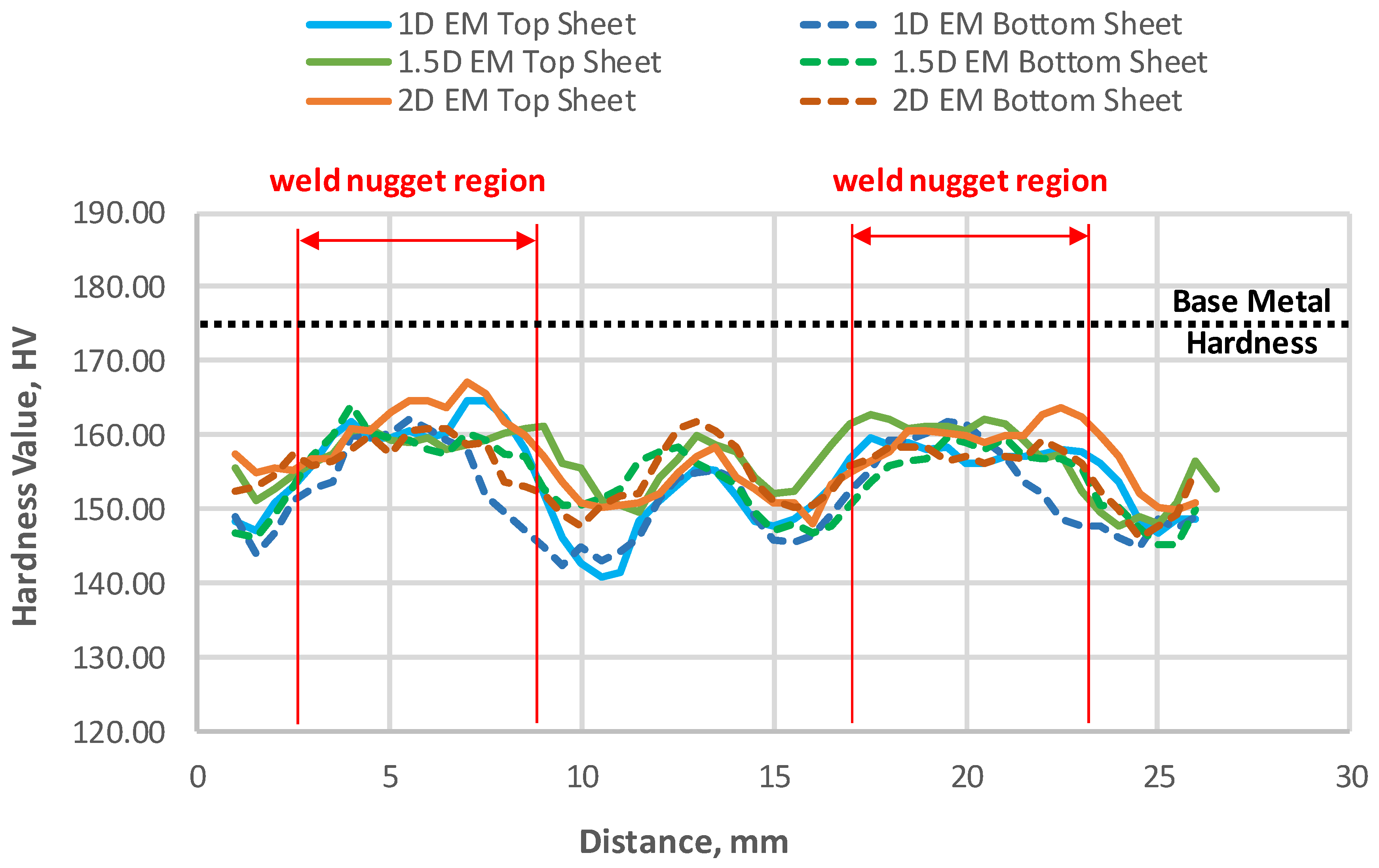
According to the microhardness maps, the hardness values of the 2D-pitch specimens and the 3D-pitch specimens are about 30 HV lower than the base metal hardness value between the two spot welds. However, the bottom sheet hardness values of the 3D-pitch and 2D-EM specimen in
Figure 17 are elevated in the midsection between the two spot welds. Perhaps the larger edge margin contributed to the heat dissipation in the 3D-pitch and 2D-EM panel during the welding process so that the bottom sheet hardness values are elevated in the midsection between the two adjacent spot welds. Both the top and bottom sheets of all the 4D-pitch specimens retained the base metal hardness value in the midsection between the two adjacent spot welds. This verifies that the 4D-pitch can prevent HAZ overlaps between two adjacent spot welds, as anticipated. The microhardness test results indicate that the 4D-pitch panels were able to retain the base metal hardness in the midsection between two adjacent spot welds, whereas the smaller pitch panels could not.
For riveted structures, a rule-of-thumb spacing between two rivet joints must be at least three times the rivet shaft diameter [
24]. In contrast, for refill-spot-welded structures there is no lower limit for the spot weld spacing, as refill spot welds can be made right next to each other. However, a smaller spot weld spacing causes HAZ overlaps that weaken the material’s strength. In addition, the edge margin for RFSSW should not be less than 1.5D, as a smaller edge margin is susceptible to edge swelling.
The research findings suggested that the 4D-pitch and the 1.5D edge margin can offer an acceptable performance for welding 1.6 mm-thick AA7075-T6 sheet metals with the 7 mm RFSSW tool. The microhardness test results supported the fact that the 4D-pitch panels demonstrate higher failure loads than those of the smaller pitch panels, as the 4D spot weld spacing allowed the 4D-pitch panels to partially retain the base metal hardness along the row of spot welds. The smaller pitch panels could not retain the base metal hardness along the row of spot welds as well as the 4D-pitch panels did. Hence, the smaller pitch panels demonstrated lower failure loads than those of the 4D-pitch panels.
4. Conclusions
The aim of this article is to chronicle an investigation into the design parameters of RFSSW for producing multi-spot-welded AA7075-T6 panels. The design parameters are the refill spot weld spacing (pitch) and the edge margin. The spot spacing or pitch is the center-to-center distance between two adjacent spot welds within the same row. An edge margin is the center-to-edge distance between the spot weld and the material edge. AA7075 is a baseline aerospace aluminum alloy used in aircraft structures. RFSSW produces three distinct weld zones in the workpiece, which are the heat-affected zone (HAZ), the Thermo-Mechanically Affected Zone (TMAZ), and the weld nugget. A refill spot weld usually starts to fail in TMAZ/HAZ, where the metal grains are coarser. Therefore, the extent of HAZ/TMAZ must be considered for finding appropriate design parameters for producing multi-refill-spot-welded structures. The experimental strategy used a DoE method to characterize the failure loads of multi-spot-welded panels in terms of the spot weld spacing, edge margin, and spot weld HAZ. According to the DoE results, the larger spot weld spacings with no HAZ overlap produced higher failure loads in multi-spot-welded panels. On the other hand, the 1D edge margin demonstrated abnormal plastic deformations, such as workpiece edge swelling and weld crown dents, during the RFSSW process. The larger edge margins did not exhibit such abnormal deformations during the welding process. All the refill spot welds demonstrated two types of mechanical failures, including nugget pullouts and top sheet breakdowns, during the static lap-shear pull tests. The larger spot weld spacings were mostly associated with nugget pullouts, and the smaller spot weld spacings were mostly associated with top sheet breakdowns.
The research findings suggested that the 4D-pitch and 1.5D edge margin can offer an acceptable performance for welding 1.6 mm-thick AA7075-T6 sheet metals with the 7 mm RFSSW tool. The microhardness test results supported the fact that the 4D-pitch panels demonstrated higher failure loads than those of the smaller pitch panels, as the 4D spot weld spacing allowed the 4D-pitch panels to partially retain the base metal hardness along the row of spot welds. The smaller pitch panels could not retain the base metal hardness along the row of spot welds as well as the 4D-pitch panels had. Hence, the smaller pitch panels demonstrated lower failure loads than those of the 4D-pitch panels.

 ,
, 


