
A Task Allocation Method for Multi-AUV Search and Rescue with Possible Target Area

School of Marine Science and Technology, Northwestern Polytechnical University, Xi’an 710072, China
*
Author to whom correspondence should be addressed.
J. Mar. Sci. Eng. 2023, 11(4), 804; https://0-doi-org.brum.beds.ac.uk/10.3390/jmse11040804
Submission received: 14 February 2023
/
Revised: 19 March 2023
/
Accepted: 7 April 2023
/
Published: 10 April 2023
(This article belongs to the Special Issue Autonomous Underwater Vehicle Technology Advances in Ocean Observation)
Abstract
:Task allocation is crucial for autonomous underwater vehicle (AUV) collaboration in multi-AUV maritime search and rescue missions. In real projects, there are possible target areas existing in task areas, which are not expected to be divided. Motivated by such a special situation, this paper proposes an area partitioning method to allocate the task to multiple AUVs and maintain the possible target area as a whole. First, the spatial structure of the task area is defined by the spiked Morse decomposition, which divides the task area according to a set of angles. Then, we perform a variational transformation to determine the optimal angles using the AUV order. Next, a customized backtracking method is introduced to determine the optimal AUV order which divides the task area among the multiple AUVs without disturbing the possible target areas. The proposed methodology is validated under various challenging scenarios using a different number of AUVs. The empirical results show that the divided possible target areas and workload variance were superior to the comparison methods. This indicates that the proposed method can generate stable solutions that effectively reduce the segmentation of possible target areas and keep the workload of the multiple AUVs balanced.
1. Introduction
Search and rescue missions are a vital application for autonomous underwater vehicles (AUV), which can cover the task area and acquire sonar data [1,2,3]. During the task, sonar images are collected by sonars installed aboard each AUV for further target identification. To reduce the operation time and increase reliability [4], multi-AUV (MAUV) systems are extensively utilized for search and rescue missions [5,6]. Furthermore, the resulting task allocation directly influences the effectiveness of the multi-AUV operation.
Among all multi-robot task allocation methods, the area partitioning method is effective and suitable for search and rescue missions to decompose the whole task for the MAUV systems [7,8] due to sonic interference from different sonars. Hence, the multi-AUV task allocation in this study is performed by an area partitioning method, which divides the task area into small sections for parallel coverage [9]. Most existing area partitioning methods are based on geometry partitioning and focus on the constraints of the multi-robot systems, such as workload balancing, managing robots based on different energy capabilities, and the complex shape of task areas [10]. Additionally, most of these methods treat the whole task area similarly without any internal distinction.
1.1. Motivation
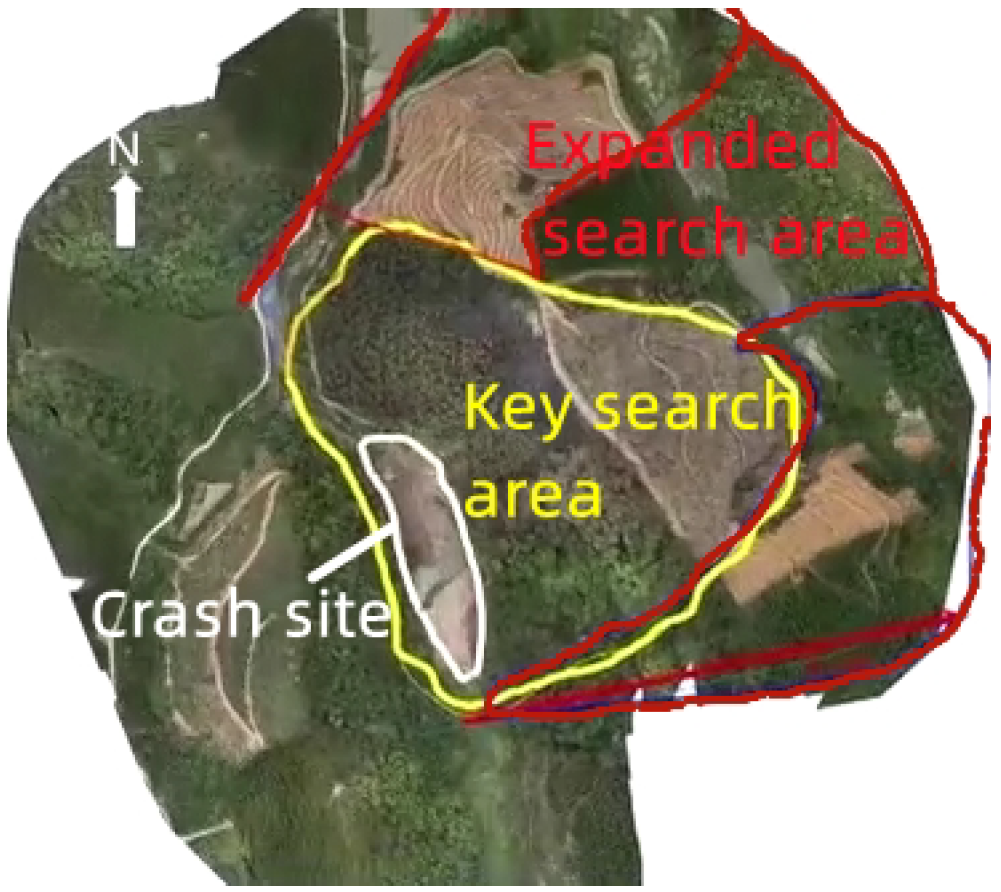
When analyzing search and rescue missions, we noticed that there are always possible target areas in the task area. For example, Figure 1 shows the real search scope of the air disaster that occurred in March 2022 in China. It can be seen that there is a crash site and a key search area, which are more likely to find the target successfully. For maritime search and rescue, concentrating the possible target area on fewer AUVs aids in the efficient detection of the target during the sonar image interpretation process. More similar examples include dangerous areas in adversarial coverage missions [11] and areas with carpets in cleaning floor tasks. For these scenarios, there are small sections in the task area, which are essential parts of the whole task and should be processed separately. However, prior area partitioning methods paid no attention to such special zones.
In this study, we look into the task allocation problem in multi-AUV search and rescue missions, which is conducted by partitioning the task area in the presence of a possible target area that should not be divided. It is also applicable for some applications; for instance, in the adversarial coverage task [11], assigning the dangerous area to fewer robots helps to guarantee the safety of the robots.
1.2. Contributions
A novel area partitioning method is presented in this study to address the task allocation problem in multi-AUV search and rescue missions with possible target areas that should be unpartitioned as much as possible. Since the deployment of AUVs is not considered in this study, it is assumed all AUVs start from the same position on the edge of the task area. The Morse decomposition in the spiked pattern is proposed to define the structure of the beehive-based task area, and the area partitioning result is determined by a set of split-line angles. Then, a variable transformation is performed, and the optimal angles are obtained by the AUV order. Considering different energy capacities, the backtracking method is customized to determine the AUV order with the purpose of keeping the workload balanced and avoiding the segmentation of the possible target areas. Simulations considering two scenarios with different numbers of AUVs are employed to verify the performance of the proposed method. From the simulation results, it can be seen that the task area is effectively decomposed, taking into account the possible target areas and workload balancing.
The main contributions of this study can be summarized as follows:
- This study first addresses the area partition problem with possible target areas in the multi-AUV area coverage task. The possible target areas are assigned to a minimum number of AUVs, which is beneficial to the performance of the mission.
- The traditional Morse decomposition is extended to discrete task areas. The Morse decomposition in the spike pattern is adopted to define the discrete spatial structure of the workspace, as all AUVs started from the same initial position.
- A customized backtracking method is developed to determine the AUV order properly in order to balance the workload of the AUVs and reduce the number of AUVs covering the possible target areas. The generated solution employing the customized backtracking method is stable and globally optimal.
This paper is organized as follows. In Section 2, the existing relevant studies of the multi-robot area coverage task allocation are summarized. In Section 3, we define the structure of the MAUV task allocation problem considering the possible target area. Section 4 presents the proposed area partitioning method. Its performance is verified via a series of computational simulations in Section 5. Finally, we give the conclusion and highlight potential future works in Section 6.
2. Related Work
Concerning generalized area coverage tasks, an exhaustive investigation of applications and approaches was provided in [5,12]. In general, existing task allocation studies have two categories: online and offline approaches. The online approaches determine the real-time motion when performing tasks, such as methods in [13,14,15,16,17]. Online approaches usually require reliable communication to share working information. However, in many cases such as underwater or large-scale environments, reliable communication is hard to guarantee. In order to reduce the requirements for working conditions, offline approaches generate dependent subtasks for robots. Most offline approaches attribute the problem to the arc routing problem (ARP) and the area partitioning problem.
As for the ARP approaches, an global path is determined in advance and then allocated to robots. Considering the energy constraints, the capacitated arc routing problem (CARP) was raised based on the ARP, which optimally selected the weighted edges of a graph-based environment. Various modified Ulusoy’s algorithms [18], such as [19,20], were put forward aiming at different scenarios and constraints. In [21], the authors provided coverage path planning for multiple Dubins robots, which first obtained the shortest Dubins coverage path and then divided the path using a tree partition strategy. Approaches in this category are suitable for a static environment due to the fixed initial route. An obvious drawback of approaches in this category is that all planned routes need to be adjusted once the task environment changes.
As for the area partitioning approaches, the task area (which might be composed of multiple unconnected areas) is divided and appropriately allocated into partitioned areas to member robots. Compared with solutions in other categories, area partitioning approaches are relatively flexible and have fewer limits on the environment and equipment. Moreover, the area partitioning approaches can reduce interference among sensor beams and collisions among robots due to spatial partitioning.
Among all area partitioning solutions, the Voronoi partitioning method [22,23,24], optimal polygon decomposition [25], and the Delaunay triangulation method [26] are the most common methods. The work [22] proposed a Voronoi-based area partitioning and allocation algorithm considering the different capabilities of robots and unstructured environments. However, the resulting overlapping area increased the workload. Another area partitioning approach named the divide areas based on robot’s initial positions (DARP) algorithm [27] decomposed the task area before area partitioning and then assigned grids according to the initial positions. The DARP algorithm has also been used to cover areas of complex shapes in many remote sensing applications [28]. However, an inevitable drawback is the heavy computational burden. Considering discontinuities (e.g., no-fly zones) in the task area, a Lloyd’s algorithm-based area partitioning method was provided for monitoring non-convex areas using multi-robots [29]. Unfortunately, the battery capacity of the robots was ignored, which decreased the reliability of the proposed method. Considering the complex land cover types in outdoor environments, a hierarchical quadtree and binary operations were employed to assign the whole task to multi-robots [30]. Nevertheless, the time complexity was still high due to the three non-parallel steps. In order to reduce task time, an optimal polygon decomposition method was put forward [25] considering the influence of wind on unmanned aerial vehicles. In this method, moving slice lines were used to divide the complex region, which is a type of Morse decomposition. A constrained Delaunay triangulation method proposed by Balampanis et al. [26] mainly dealt with complex geometries and workload balancing. It can be deduced that workload balancing, different energy capabilities, and complex shapes of task areas were highlighted in most existing studies.
Based on the existing methods, we develop a novel method for partitioning task areas considering the possible target areas to allocate the coverage task to multi-AUV systems. In real-world applications, examples of special zones include highly possible target areas in search and rescue missions [3], dangerous areas in adversarial coverage [11], carpet areas in floor cleaning, and so on. Moreover, workload balancing is essential for multi-AUV tasks, which is considered in this study.
3. Problem Definition and Assumptions
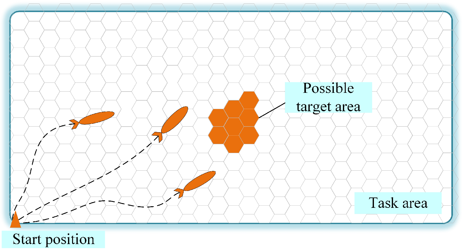
A multi-AUV system equipped with side-scan sonar is assigned for the search and rescue mission with a possible target area. Side-scan sonar scans the seabed and generates sonar images for interpretation of targets. The search and rescue mission is spatially divisible and parallelizable to allow each AUV to independently perform its subtasks. Figure 2 describes the overview of the area coverage task, including the beehive-based task area, the possible target areas, the multiple AUVs, and their start position. The discrete task area consists of multiple hexagonal grids, referred to as ‘grids’ in the following.
Let A be a convex task area, which is open and flat without obstacles. From [27], it is assumed that the task area has been decomposed into grids denoted by . This assumption is reasonable since a common way to completely cover an area is to visit all waypoints distributed in the area. The size of each of the grids is determined by the range of the sensors. Moreover, there are possible target areas represented as . It is required that a fewer number of AUVs are employed for covering these special areas.
Assume homogenous AUVs denoted as are cooperatively covering the task area, where . The AUVs’ identifiers are the serial numbers assigned beforehand. It is assumed that the energy consumption of each of the AUVs is different. Let denote the energy capacity of each AUV. The ranges from 1 to 0, where 1 denotes a full battery and 0 denotes a completely depleted battery. Certainly, the AUV with a stronger energy capacity should be assigned more workload, i.e., more grids. Hence, according to the energy capacity, the expected number of grids for AUV , denoted as , is formulated as
It is assumed the energy capacity is enough to cover the corresponding number of grids. Moreover, as mentioned, all the AUVs start from the same start position since this study does not discuss the selection of the initial positions of the AUVs. Hence, subareas for each AUV should be continuous and close to the start position to reduce energy consumption.
Based on these assumptions and considerations, the final goal is to partition the beehive-based workspace with possible target areas for AUVs with different energy capacities. Let denote the partitioned subareas; the area partitioning problem is formulated as follows:
where is the number of possible target areas after area partitioning and is the real number of grids assigned to after partitioning. The minimum represents the minimum number of divisions of the possible target areas. The minimum stands for the most optimal assignment of workload to each of the AUVs.
4. Morse-Decomposition-Based Discrete Area Partitioning Method
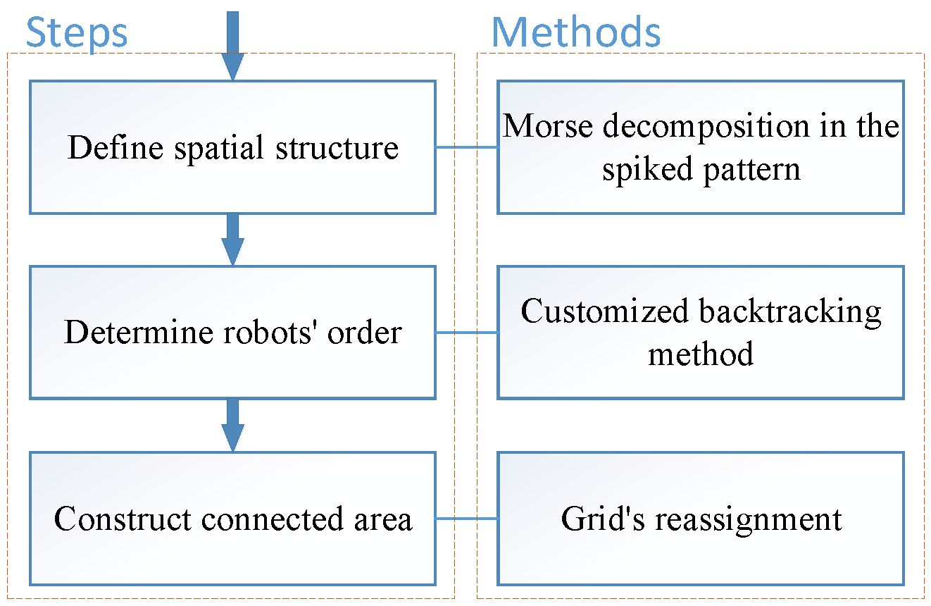
This section presents the technical details of the proposed Morse-decomposition-based discrete area partitioning method for area coverage in task allocation. The Morse decomposition in the spike pattern defines the spatial structure of the discrete task area. Subsequently, a customized backtracking method is proposed to adjust the sequence of AUVs and determine the optimal split lines. Finally, we add an operation to guarantee the continuity of the segmented subareas. The details of the above steps are illustrated in the following sections. The whole process of the proposed method includes three steps, which are depicted in Figure 3.
4.1. Define the Structure of the Discrete Task Area
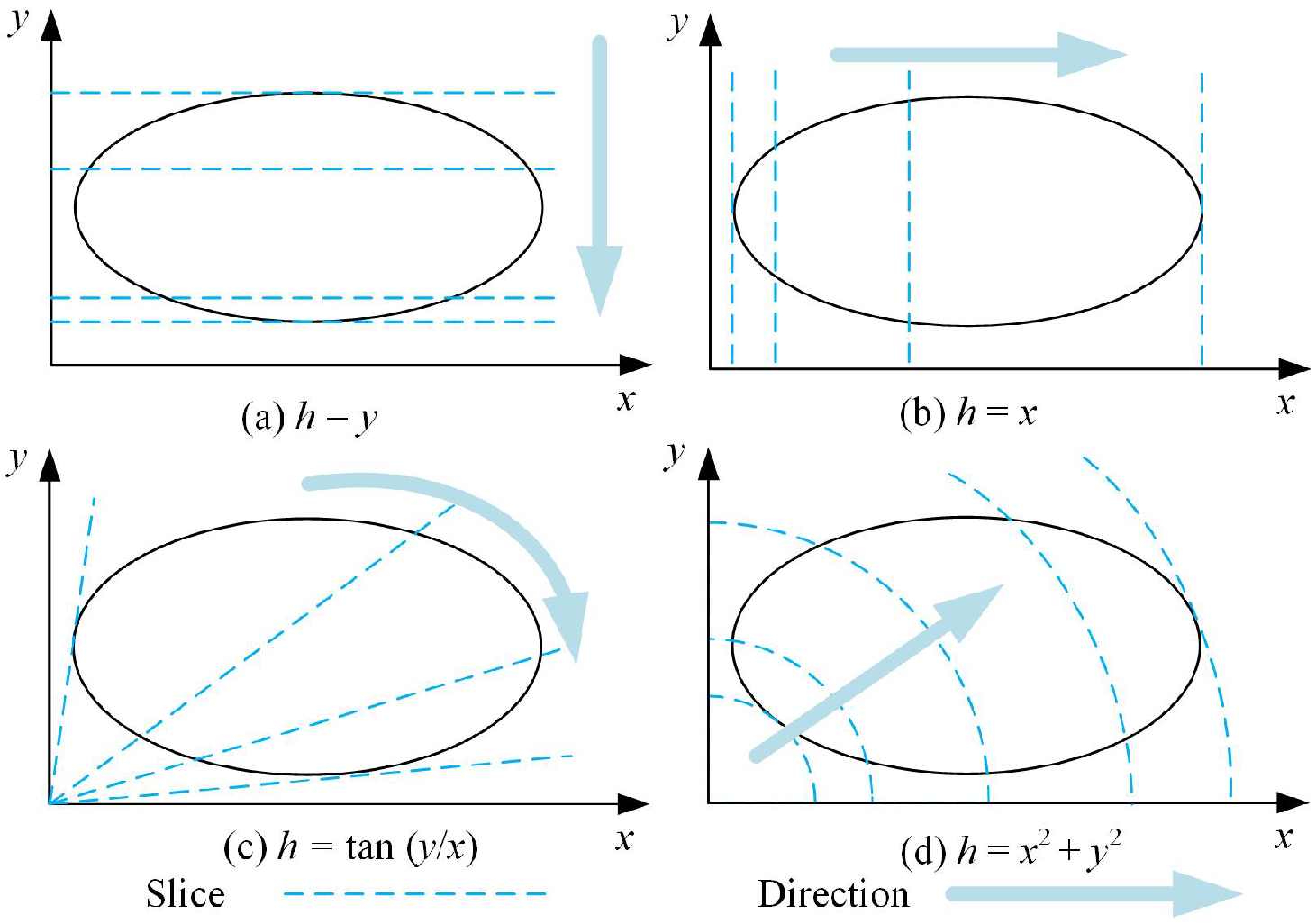
A Morse decomposition in the spike pattern is developed to define the spatial structure of the discrete task area. This lays the foundation for optimally generating the subareas. As is known, the classical Morse decomposition method provides simple and generalized decomposition structures [31,32,33]. The main idea is to use a slice to sweep the region and focus on connectivity fluctuations. Figure 4 shows four Morse decomposition patterns with different slices and directions.
The decomposition shown in Figure 4c, known as the Morse decomposition in the spike pattern, is used to outline the spatial structure of the task area. The main reason for selecting the spike pattern is that all AUVs start from the same position. The spike pattern reduces the distance between the start position and the subarea, which is impossible for other patterns of Morse decomposition.
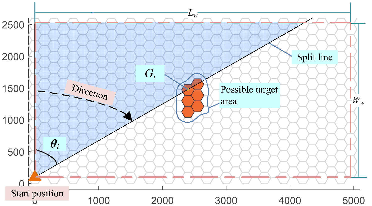
In this study, the traditional Morse decomposition in the spike pattern is extended to the discrete space. Figure 5 gives the related definitions, including the start position, the possible target area, and the split line decided by the grid . Incidentally, the hexagonal grid in this scenario can be replaced with any other polygon as long as it seamlessly covers the task area.
From Figure 5, the slice is defined as the line joining the center of the first grid and the center of the grid . A set of slices can be treated as split lines to divide the task area. Then, we give the definition of the angle .
Definition 1.
The angle between the y-axis and the slice of grid is defined as
where and are coordinates of the grid , , and is the start position.
According to Definition 1, split lines are determined by the start position and angles (see an example of the split line in Figure 5). When all the angles and split lines are estimated, the task area can be partitioned.
Let be the collection of all the angles . Thus, the area partitioning problem is transformed to find elements from .
4.2. Determine the Optimal Split Lines
In this part, we find the optimized split lines by three steps. Initially, we cater for the conditions of to optimize and in Equation (2). Then, the variable is further transformed based on the order of the AUVs. Finally, the customized backtracking method is proposed to solve the optimal order of the AUVs.
4.2.1. Objective Functions of
Let denote the solution required in this study. Next, we deduce the conditions of to optimize and in Equation (2).
In terms of in Equation (2), i.e., the workload balancing, the number of grids assigned to AUV , i.e., the , is regarded as the workload. For a given , let denote the number of grids that satisfies , i.e.,
In Figure 5, the is the number of grids in the blue area. Furthermore, the workloads determined by are
Given the definitions of and W, from Equation (2) can be transformed into: Hence, to minimize , should satisfy
While dealing with in Equation (2), i.e., avoiding the partitioning of possible target areas, it should be ensured that split lines should avoid falling into any possible target area. Let denote the of the grids in each possible target area . Then, we can define as
If the of split lines belongs to , the possible target area must be divided. Thus, to guarantee no split line passes the possible target areas, should satisfy
4.2.2. Find the Optimal
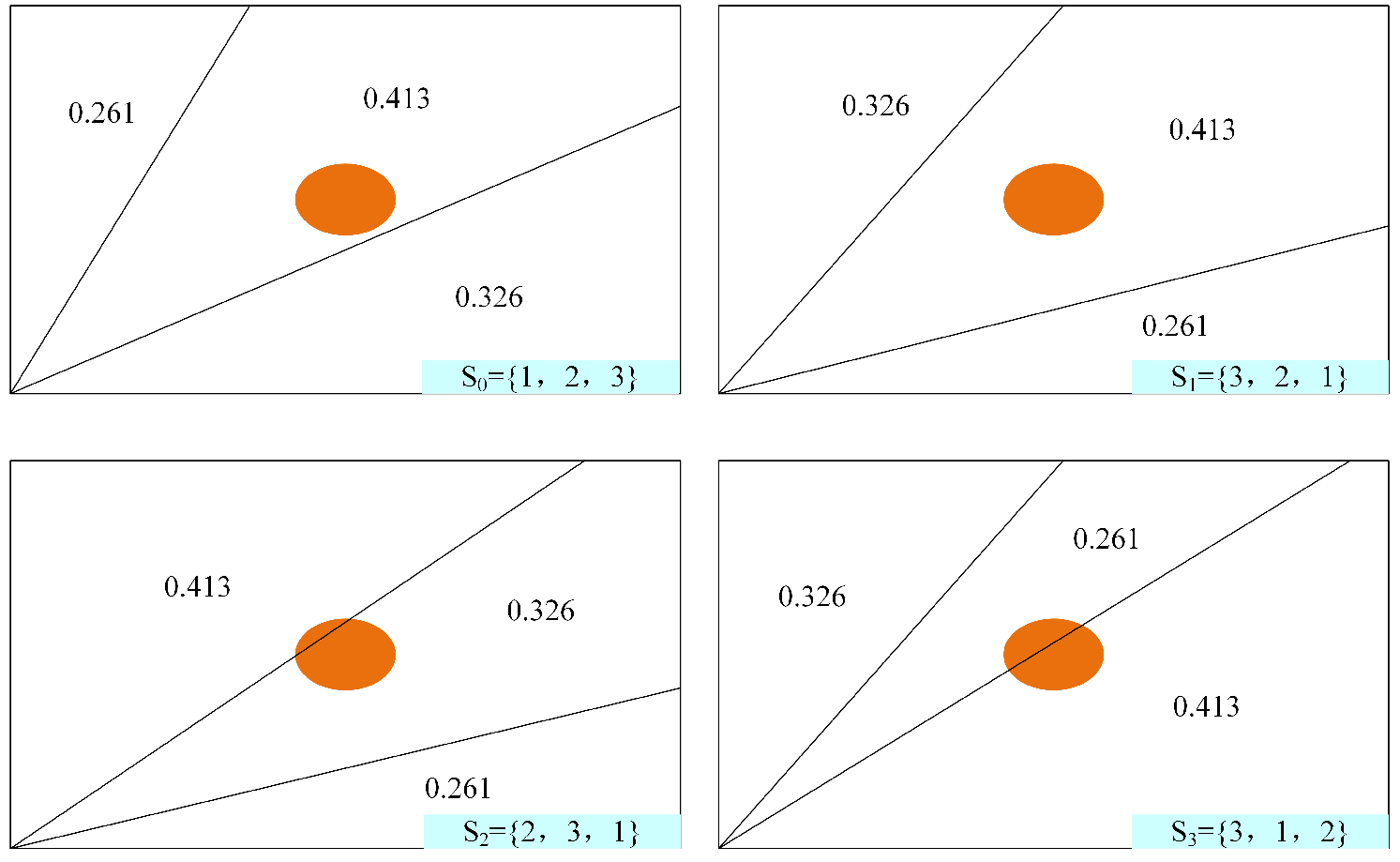
This section elaborates the customized backtracking method to determine the satisfying by adjusting the order of the AUVs. The proposed customized backtracking method assigns workloads according to the results of Equation (1). Then, it adjusts the order of the AUVs to avoid the split lines passing the possible target areas. The variable conversion guarantees the minimization of and reduces the computational complexity. Take Figure 6 as an example. The segmentation of the possible target areas can be avoided by changing the order of the AUVs. Simultaneously, the workload balancing can also be made optimal.
The AUVs’ identifiers are expressed as , which are in the order of the energy capacity of each of the AUVs. The order of the AUVs is represented as , where indicates the identifier of the AUV that is placed in the i-th position. For instance, indicates that the AUV whose identifier is ‘5’ will be the second AUV in the predefined direction.
The backtracking method is customized to determine the order of the AUVs inspired by the N-Queen problem [34]. Similar to finding the proper positions for Queens, this study aims to find the proper position for the AUVs. The backtracking method is a depth-first search algorithm. Based on the traditional position selection strategy for the N-Queen problem, the customized backtracking method neglects diagonal attacks and adds the process of checking if the is included in and is incorporated.
The detailed procedure of the customized backtracking method is illustrated in Algorithm 1. The most important steps (Lines 3–11) are the iterative selection of the most suitable AUV order until all AUVs are optimally arranged. For each position, is calculated. If satisfies Equation (8), we continue to find the AUV for the next position, or else we try other candidate AUVs. If all candidate AUVs are unavailable, the robot in the last position is changed. If possible target areas must be partitioned, i.e., there is no solution without partitioning possible target areas, the order S with minimum is chosen as the optimal solution.
| Algorithm 1 Customized backtracking method in Morse decomposition. |
| Input: Output: , , S 1: Initialize: , 2: while do 3: while do 4: if is available then 5: ←j 6: break 7: else 8: j←j +1 9: ← 10: compare and record 11: 12: end if 13: end while 14: if then 15: , j← 1 16: else 17: BACKTRACKING 18: end if 19: if all elements in are settled then 20: calculate 21: , 22: end if 23: end while 24: if S is ∅ then 25: ← 26: 27: calculate 28: end if |
4.3. Construct Connected Subareas
The generated subareas by the aforementioned processes can roughly assign the task area into subareas. However, the continuity of subareas cannot be guaranteed, especially in case the difference between two adjacent is small. To address this problem, an additional procedure is introduced for constructing spatial connected areas.
Algorithm 2 describes the main procedure. Let expresses the all grids assigned to AUV . After computing the allocation matrix according to the current assignment, the body region P and the rest regions Q of each subarea are obtained. Then, for AUV , all grids connecting and , denoted as , are calculated. In addition, the expresses the boundary grids assigned to two adjacent AUVs. All grids in and are assessed and reallocated. Thus, the continuity of the partitioned areas is ensured, and the number of grids for the AUVs is adjusted to be as close as possible to in Equation (1).
| Algorithm 2 Constructing connected areas. |
| Input: ,, Output: ,, 1: for to do 2: Calculate , 3: Calculate and 4: while do 5: 6: 7: if then 8: 9: else 10: 11: end if 12: Update , , , and 13: end while 14: end for |
5. Simulation Results
In this section, simulations considering two different scenarios are implemented to assess the performance of the proposed area partitioning method. The simulations and analysis of the results were performed using MATLAB. The simulation results give the area partitioning result for different numbers of AUVs and the comparison to two existing area partitioning methods. Finally, results and discussions are given to thoroughly analyze the proposed method and verify its ability to handle different cases.
5.1. Scenarios and Performance Metrics
During analysis, AUVs were assigned the coverage task in a 5000 m by 2500 m rectangular area for . The task area had a small area as the start position. The radius of the hexagon grids was set as 100 m, which can be adjusted according to the range of the equipped sensor. The whole area was required to be partitioned into subareas based on area partitioning methods. Furthermore, the energy capacities of AUVs were randomly set as . The value of determines the number of values taken from ; for instance, if , then . For clarity of presentation, Table 1 summarizes the basic parameters of the task scenario in the simulation.
Under these configurations, two cases were analyzed to validate the proposed method for different environments. The basic task area of the two cases was the same. The difference between the two scenarios was the number and location of possible target areas. In Case 1, we considered the scenario as shown in Figure 5, while in Case 2, the scenario with scattered possible target areas was considered.
To validate the effectiveness of our method, we compare our method with two existing approaches, i.e., the generalized Voronoi diagram (GVD) [23] and the boustrophedon and backtracking (BoB) method [15]. The GVD is a common area partitioning method, while the BoB method is based on the boustrophedon coverage method, which also considers the workload balancing. As the possible target area partitioning method is proposed, we compare two related methods that can be applied in our context.
For analyzing the performance, two metrics are employed, including the ability to keep the possible target areas undivided and workload balancing. This is in correspondence with the objective functions and . A smaller value of indicates less partitioning of the possible target areas, while a smaller indicates that the square difference between the practical number of assigned grids and the expected number of assigned grids is small, and hence, the workload is optimally balanced.
5.2. Case 1: One Special Zone
This case study aims to verify the proposed method with one possible target area in the whole area. The beehive-based workspace and the possible target area are shown in Figure 5.
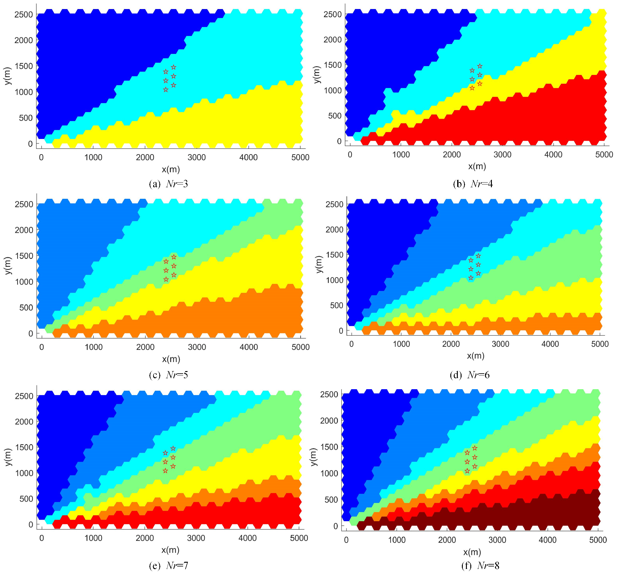
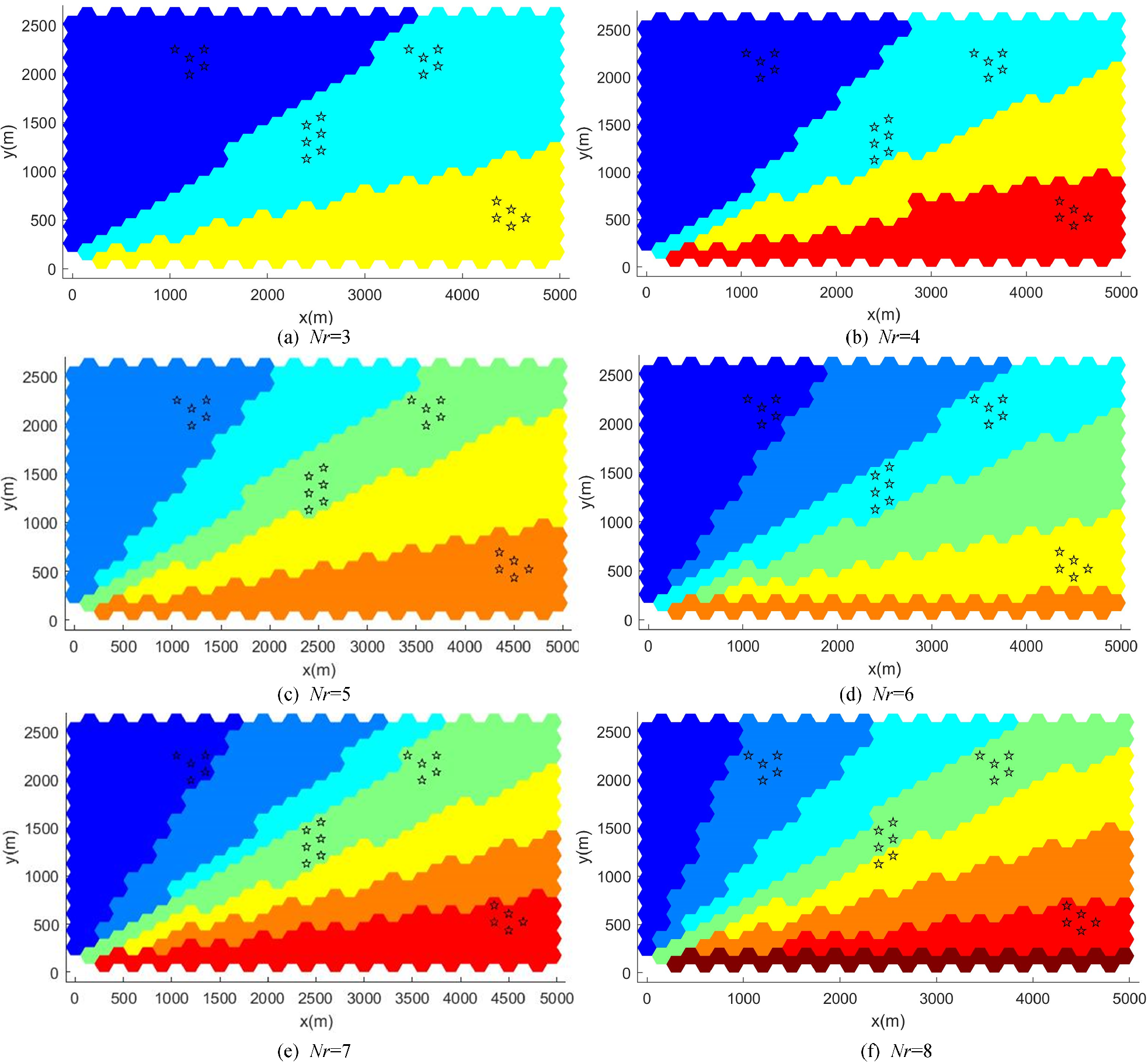
Table 2 lists the numerical results using the proposed method, including the order S and angles of split lines for . Figure 7 shows the resultant area partitioning according to Table 2. Grids in the possible target area are marked with red stars, and grids assigned to different AUVs are shown with different colors. From the graph, it is clear that the possible target area is unpartitioned for . In the other two cases, the possible target area is divided into only two parts. Hence, the proposed method can generate continuous subareas and ensure less division of the possible target areas.
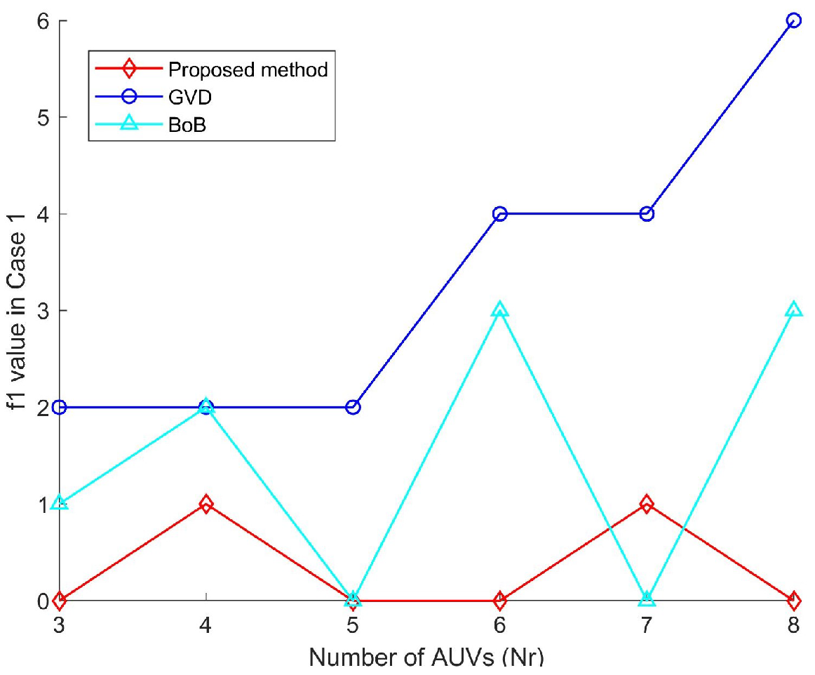
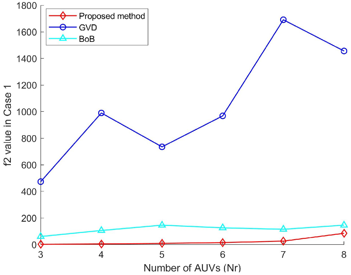
The comparison of for the proposed method, the GVD method, and the BoB method are summarized in Figure 8. The values of the proposed method (red line) stay lower than the other two compared methods and do not increase with the number of AUVs. The maximum of the proposed method is 1; that is, there is at most one extra partitioned possible target area using the proposed method. The BoB method has a higher fluctuation and shows a slight growth with the number of AUVs, while the of GVD method (blue line) also rises with the number of AUVs. This indicates that the proposed method can better protect the area from partitioning.
Figure 9 shows the comparison of the value of the three compared methods, which measures the difference between the expected and practical number of grids assigned to each AUV. It can be seen that the of the proposed method remains stable and maintains a small increase with the number of AUVs. However, the of the BoB method (cyan line) is slightly higher than the proposed method. The GVD method has a worse performance regarding workload balancing. Therefore, the proposed method has a better ability for workload balancing compared to the other two approaches.
In summary, for Case 1, the proposed method shows a significant increase in the ability to keep the completeness of the possible target areas and assign grids reasonably for .
5.3. Case 2: Scattered Special Zones
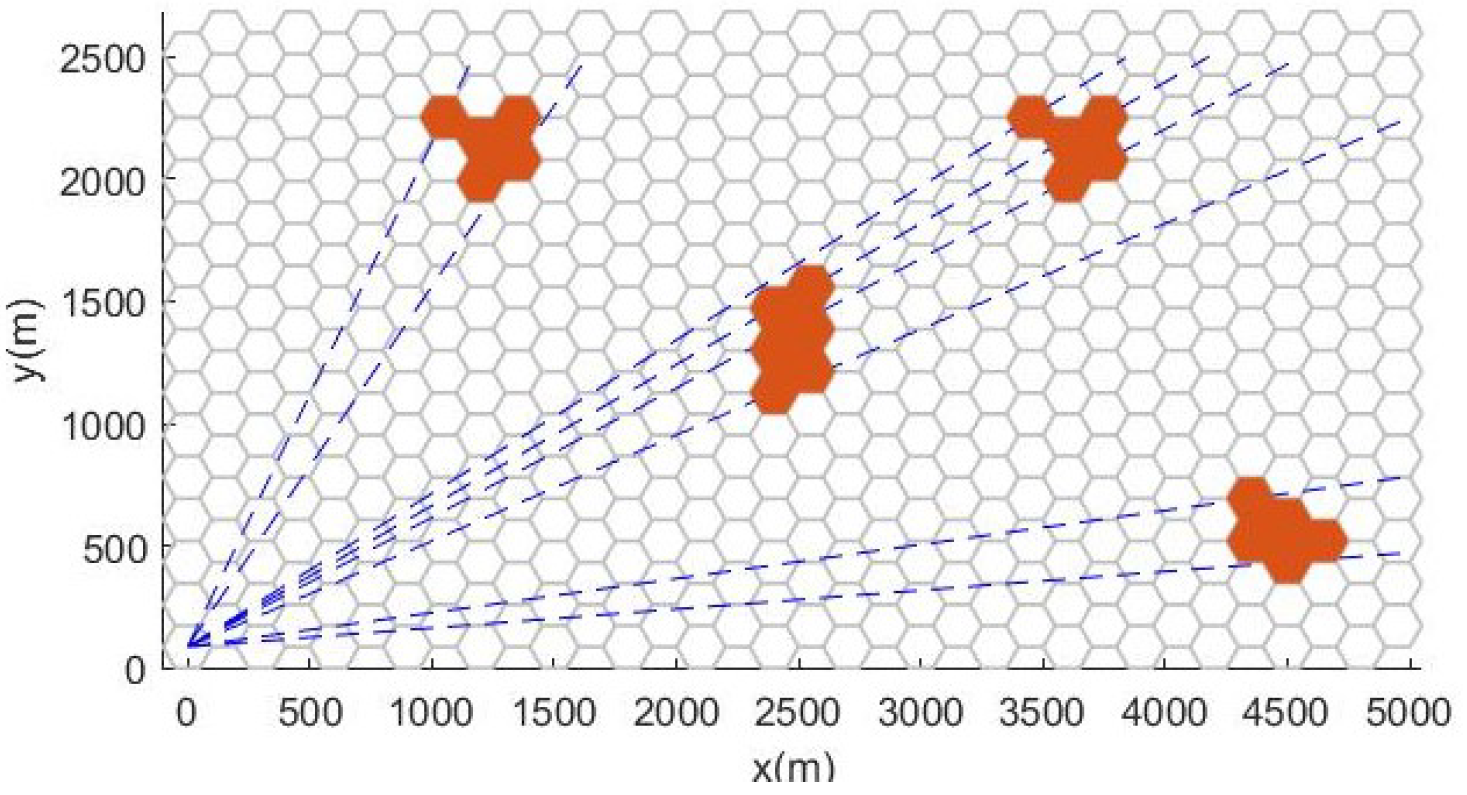
In this analysis, a new workspace with several small possible target areas was designed as depicted in Figure 10. The area partitioning result using the proposed method is given. Furthermore, the performance of the proposed method in comparison to the BoB and GVD approach is analyzed on the defined area.
The numerical results of the proposed method are summarized in Table 3, while the area decomposition results are represented in Figure 11. Grids in possible target areas are marked with black stars, and grids assigned to different AUVs are filled using different colors. It is clear that the subareas assigned to different AUVs were continuous and started from the grids closer to the start position. For , the possible target areas were not divided, while for , there was only one additional possible target area caused by the area partitioning.
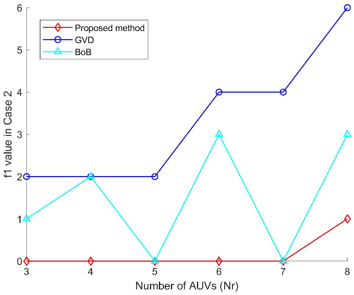
Similarly, the performance of the proposed method in avoiding segmentation of the possible target area is shown in Figure 12. In most cases, the values of the proposed method stay zero except for . The maximum value of for the proposed method is 1, which indicates only a single subzone is added, which is considered acceptable. However, the of the other two approaches has large fluctuations and significantly increases with the number of AUVs. Hence, even though the workload balancing was considered in the BoB method, the proposed method is still more conducive to protecting the division of the possible target areas.
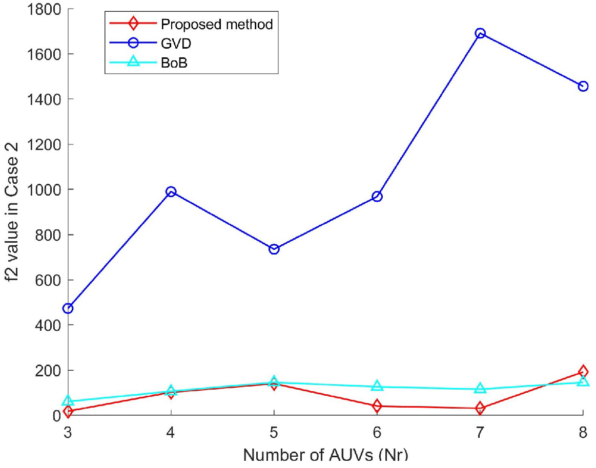
In case 2, the comparison of is shown in Figure 13. As is indicated in the figure, the of the proposed method keeps close but is lower than the BoB method. However, the GVD method is significantly higher than the other two methods and increases with the number of AUVs. This indicates that the proposed method is effective in balancing the workload. Furthermore, smaller grids result in better workload balancing.
Based on the aforementioned results, the proposed method’s area partitioning results have the following characteristics: (1) possible target areas are rarely partitioned, (2) the numbers of grids assigned to each AUV are close to the expected numbers, and (3) partitioned subareas are continuous and close to the start position. Hence, it can be concluded that the proposed method is more effective in avoiding the partitioning of the possible target areas and provides optimal workload balancing.
6. Conclusions
Considering the possible target areas in multi-AUV area coverage tasks, this study provided a task allocation method that partitions the beehive-based task area and assigns subareas to AUVs. Simulation results in different scenarios reveal that the proposed method can avoid the partitioning of the possible target areas and keep the workload balanced among the AUVs. The exemption of dividing the possible target area is essential in many area coverage tasks, such as adversarial coverage and search and rescue missions. The proposed approach is ideally suited for such applications. In the proposed method, the area partition problem with possible target areas in the multi-AUV area coverage task was first addressed. Furthermore, Morse decomposition was applied in the discrete task area. The proposed method is suggested for convex task areas limited by Morse decomposition. As a future work, a tailored path planner will be studied for covering the task area with possible target areas. Moreover, the practical factors that have an effect on operational performance will be taken into account, such as the unevenness of the seabed and underwater currents.
Author Contributions
Conceptualization, C.C. and J.C.; methodology, C.C.; validation, C.C. and F.L.; writing—original draft preparation, C.C.; writing—review and editing, J.C. and M.S.A.; supervision, J.C.; funding acquisition, F.L. All authors have read and agreed to the published version of the manuscript.
Funding
This research was funded by National Natural Science Foundation of China grant number 62071383.
Institutional Review Board Statement
Not applicable.
Informed Consent Statement
Not applicable.
Data Availability Statement
Data is contained within the article.
Acknowledgments
The authors acknowledge editors and reviewers for their comments and suggestions.
Conflicts of Interest
The authors declare no conflict of interest.
References
- Parker, G.; Zbeda, R. Learning Area Coverage for a Self-sufficient Hexapod Robot Using a Cyclic Genetic Algorithm. IEEE Syst. J. 2014, 8, 778–790. [Google Scholar] [CrossRef]
- Cho, S.W.; Park, H.J.; Lee, H.; Shim, D.H.; Kim, S.Y. Coverage Path Planning for Multiple Unmanned Aerial Vehicles in Maritime Search and Rescue Operations. Comput. Ind. Eng. 2021, 161, 107612. [Google Scholar] [CrossRef]
- Ai, B.; Jia, M.; Xu, H.; Xu, J.; Wen, Z.; Li, B.; Zhang, D. Coverage Path Planning for Maritime Search and Rescue Using Reinforcement Learning. Ocean Eng. 2021, 241, 110098. [Google Scholar] [CrossRef]
- Nair, V.G.; Guruprasad, K. MR-SimExCoverage: Multi-robot Simultaneous Exploration and Coverage. Comput. Electr. Eng. 2020, 85, 106680. [Google Scholar] [CrossRef]
- Almadhoun, R.; Taha, T.; Seneviratne, L.; Zweiri, Y. A Survey on Multi-robot Coverage Path Planning for Model Reconstruction and Mapping. SN Appl. Sci. 2019, 1, 847. [Google Scholar] [CrossRef] [Green Version]
- Savkin, A.V.; Huang, H. Asymptotically Optimal Path Planning for Ground Surveillance by a Team of UAVs. IEEE Syst. J. 2022, 16, 3446–3449. [Google Scholar] [CrossRef]
- Alitappeh, R.J.; Jeddisaravi, K. Multi-robot Exploration in Task Allocation Problem. Appl. Intell. 2021, 52, 2189–2211. [Google Scholar] [CrossRef]
- Seenu, N.; Kuppan Chetty, R.M.; Ramya, M.M.; Janardhanan, M.N. Review on State-of-the-art Dynamic Task Allocation Strategies for Multiple-robot Systems. Ind. Robot 2020, 47, 929–942. [Google Scholar] [CrossRef]
- Acevedo, J.J.; Arrue, B.C.; Maza, I.; Ollero, A. A Distributed Algorithm for Area Partitioning in Grid-shape and Vector-shape Configurations with Multiple Aerial Robots. J. Intell. Robot. Syst. 2015, 84, 543–557. [Google Scholar] [CrossRef]
- Tang, Y.; Zhou, R.; Sun, G.; Di, B.; Xiong, R. A Novel Cooperative Path Planning for Multirobot Persistent Coverage in Complex Environments. IEEE Sens. J. 2020, 20, 4485–4495. [Google Scholar] [CrossRef]
- Yehoshua, R.; Agmon, N.; Kaminka, G.A. Robotic Adversarial Coverage of Known Environments. Int. J. Rob. Res. 2016, 35, 1419–1444. [Google Scholar] [CrossRef]
- Galceran, E.; Carreras, M. A Survey on Coverage Path Planning for Robotics. Robot. Auton. Syst. 2013, 61, 1258–1276. [Google Scholar] [CrossRef] [Green Version]
- Zhu, D.; Tian, C.; Jiang, X.; Luo, C. Multi-AUVs Cooperative Complete Coverage Path Planning Based on GBNN Algorithm. In Proceedings of the Undefined2017 29th Chinese Control And Decision Conference (CCDC), Chongqing, China, 28–30 May 2017; IEEE: Piscataway, NJ, USA, 2017. [Google Scholar] [CrossRef]
- Tsiogkas, N.; Lane, D.M. An Evolutionary Algorithm for Online, Resource-constrained, Multivehicle Sensing Mission Planning. IEEE Robot. Autom. Lett. 2018, 3, 1199–1206. [Google Scholar] [CrossRef] [Green Version]
- Viet, H.H.; Dang, V.H.; Choi, S.; Chung, T.C. BoB: An Online Coverage Approach for Multi-robot Systems. Appl. Intell. 2014, 42, 157–173. [Google Scholar] [CrossRef]
- Zhong, J.; Cheng, H.; He, L.; Ouyang, F. Decentralized Full Coverage of Unknown Areas by Multiple Robots with Limited Visibility Sensing. IEEE Robot. Autom. Lett. 2019, 4, 338–345. [Google Scholar] [CrossRef]
- Zhou, B.; Xu, H.; Shen, S. RACER: Rapid Collaborative Exploration With a Decentralized Multi-UAV System. IEEE Trans. Robot. 2023, 1–20. [Google Scholar] [CrossRef]
- Ulusoy, G. The Fleet Size and Mix Problem for Capacitated Arc Routing. Eur. J. Oper. Res. 1985, 22, 329–337. [Google Scholar] [CrossRef]
- Sipahioglu, A.; Kirlik, G.; Parlaktuna, O.; Yazici, A. Energy Constrained Multi-robot Sensor-based Coverage Path Planning Using Capacitated Arc Routing Approach. Robot. Auton. Syst. 2010, 58, 529–538. [Google Scholar] [CrossRef]
- Yazici, A.; Kirlik, G.; Parlaktuna, O.; Sipahioglu, A. A Dynamic Path Planning Approach for Multirobot Sensor-Based Coverage Considering Energy Constraints. IEEE Trans. Cybern. 2014, 44, 305–314. [Google Scholar] [CrossRef]
- Li, L.; Shi, D.; Jin, S.; Yang, S.; Zhou, C.; Lian, Y.; Liu, H. Exact and Heuristic Multi-Robot Dubins Coverage Path Planning for Known Environments. Sensors 2023, 23, 2560. [Google Scholar] [CrossRef]
- Hassan, M.; Liu, D. Simultaneous Area Partitioning and Allocation for Complete Coverage by Multiple Autonomous Industrial Robots. Auton. Robot. 2017, 41, 1609–1628. [Google Scholar] [CrossRef]
- Nair, V.G.; Guruprasad, K.R. GM-VPC: An Algorithm for Multi-robot Coverage of Known Spaces Using Generalized Voronoi Partition. Robotica 2019, 38, 845–860. [Google Scholar] [CrossRef]
- Zhao, Z.; Zhu, B.; Zhou, Y.; Yao, P.; Yu, J. Cooperative Path Planning of Multiple Unmanned Surface Vehicles for Search and Coverage Task. Drones 2023, 7, 21. [Google Scholar] [CrossRef]
- Coombes, M.; Fletcher, T.; Chen, W.H.; Liu, C. Optimal Polygon Decomposition for UAV Survey Coverage Path Planning in Wind. Sensors 2018, 18, 2132. [Google Scholar] [CrossRef] [PubMed] [Green Version]
- Balampanis, F.; Maza, I.; Ollero, A. Area Partition for Coastal Regions with Multiple UAS. J. Intell. Robot. Syst. 2017, 88, 751–766. [Google Scholar] [CrossRef]
- Kapoutsis, A.C.; Chatzichristofis, S.A.; Kosmatopoulos, E.B. DARP: Divide Areas Algorithm for Optimal Multi-robot Coverage Path Planning. J. Intell. Robot. Syst. 2017, 86, 663–680. [Google Scholar] [CrossRef] [Green Version]
- Apostolidis, S.D.; Kapoutsis, P.C.; Kapoutsis, A.C.; Kosmatopoulos, E.B. Cooperative Multi-UAV Coverage Mission Planning Platform for Remote Sensing Applications. Auton. Robot. 2022, 46, 373–400. [Google Scholar] [CrossRef]
- Collins, L.; Ghassemi, P.; Esfahani, E.T.; Doermann, D.; Dantu, K.; Chowdhury, S. Scalable Coverage Path Planning of Multi-Robot Teams for Monitoring Non-Convex Areas. In Proceedings of the Undefined2021 IEEE International Conference on Robotics and Automation (ICRA), Xi’an, China, 30 May–5 June 2021; IEEE: Piscataway, NJ, USA, 2021. [Google Scholar] [CrossRef]
- Huang, X.; Sun, M.; Zhou, H.; Liu, S. A Multi-Robot Coverage Path Planning Algorithm for the Environment with Multiple Land Cover Types. IEEE Access 2020, 8, 198101–198117. [Google Scholar] [CrossRef]
- Acar, E.U.; Choset, H.; Rizzi, A.A.; Atkar, P.N.; Hull, D. Morse Decompositions for Coverage Tasks. Int. J. Robot. Res. 2002, 21, 331–344. [Google Scholar] [CrossRef]
- Guastella, D.C.; Cantelli, L.; Giammello, G.; Melita, C.D.; Spatino, G.; Muscato, G. Complete Coverage Path Planning for Aerial Vehicle Flocks Deployed in Outdoor Environments. Comput. Electr. Eng. 2019, 75, 189–201. [Google Scholar] [CrossRef]
- Balampanis, F.; Maza, I.; Ollero, A. Area Decomposition, Partition and Coverage with Multiple Remotely Piloted Aircraft Systems Operating in Coastal Regions. In Proceedings of the Undefined 2016 International Conference on Unmanned Aircraft Systems (ICUAS), Arlington, VA, USA, 7–10 June 2016; IEEE: Piscataway, NJ, USA, 2016. [Google Scholar] [CrossRef]
- Guldal, S.; Baugh, V.; Allehaibi, S. N-queens Solving Algorithm by Sets and Backtracking. In Proceedings of the UndefinedSoutheastCon 2016, Norfolk, VA, USA, 30 March–3 April 2016; IEEE: Piscataway, NJ, USA, 2016. [Google Scholar] [CrossRef]
Figure 1.
The search area for finding the airplane that crashed in China in March 2022. The whole task area includes the crash site, the key search area, and the expanded search area. The three types of subareas are of different importance.
Figure 1.
The search area for finding the airplane that crashed in China in March 2022. The whole task area includes the crash site, the key search area, and the expanded search area. The three types of subareas are of different importance.

Figure 2.
The general scenario of the coverage task. A multi-AUV system equipped with sensors is employed to cover the beehive-based task area with a possible target area.
Figure 2.
The general scenario of the coverage task. A multi-AUV system equipped with sensors is employed to cover the beehive-based task area with a possible target area.

Figure 3.
The whole process of the proposed area partitioning method from building structure of the area partitioning problem using Morse decomposition, roughly assigning grids by customized backtracking method, to fine adjusting to construct connected subareas.
Figure 3.
The whole process of the proposed area partitioning method from building structure of the area partitioning problem using Morse decomposition, roughly assigning grids by customized backtracking method, to fine adjusting to construct connected subareas.

Figure 4.
Four examples of Morse decomposition in different patterns.

Figure 5.
Definitions of the Morse decomposition in the spike pattern for the discrete task area.

Figure 6.
The split lines with different orders of AUVs. The workloads of AUVs are 0.261, 0.413, and 0.326, respectively. By changing the AUVs’ order, the split lines can be prevented from passing through the possible target area.
Figure 6.
The split lines with different orders of AUVs. The workloads of AUVs are 0.261, 0.413, and 0.326, respectively. By changing the AUVs’ order, the split lines can be prevented from passing through the possible target area.

Figure 7.
The workspace is partitioned into subareas using the proposed method for . Grids assigned to different AUVs are shown with different colors. Red stars denote the grids in possible target areas.
Figure 7.
The workspace is partitioned into subareas using the proposed method for . Grids assigned to different AUVs are shown with different colors. Red stars denote the grids in possible target areas.

Figure 8.
The value of the proposed method, the BoB method, and the GVD approach in Case 1 where is from 3 to 8. The smaller value indicates fewer divisions of the possible target areas.
Figure 8.
The value of the proposed method, the BoB method, and the GVD approach in Case 1 where is from 3 to 8. The smaller value indicates fewer divisions of the possible target areas.

Figure 9.
The comparison of the value of the three methods for . The smaller value indicates better ability of workload balancing.
Figure 9.
The comparison of the value of the three methods for . The smaller value indicates better ability of workload balancing.

Figure 10.
The scenario to be partitioned in Case 2. The scattered possible target areas (red zones) are distributed in the workspace. The broken blue lines show the boundaries of possible target area.
Figure 10.
The scenario to be partitioned in Case 2. The scattered possible target areas (red zones) are distributed in the workspace. The broken blue lines show the boundaries of possible target area.

Figure 11.
The workspace is partitioned according to the energy capability of AUVs using the proposed method. Grids assigned to different AUVs are shown with different colors. The black stars are possible target areas.
Figure 11.
The workspace is partitioned according to the energy capability of AUVs using the proposed method. Grids assigned to different AUVs are shown with different colors. The black stars are possible target areas.

Figure 12.
The comparison of value between the proposed method and the other two approaches in Case 2. The smaller value indicates fewer divisions of the possible target areas.
Figure 12.
The comparison of value between the proposed method and the other two approaches in Case 2. The smaller value indicates fewer divisions of the possible target areas.

Figure 13.
The comparison of the value among the proposed method, the GVD method, and the BoB method in Case 2. The smaller value indicates better ability of workload balancing.
Figure 13.
The comparison of the value among the proposed method, the GVD method, and the BoB method in Case 2. The smaller value indicates better ability of workload balancing.


Table 1.
Simulation parameters.
| Category | Item | Value |
|---|---|---|
| Task area | Length (m) | 5000 |
| Width (m) | 2500 | |
| Hexagonal grid | Radius (m) | 100 |
| AUV | Number | 3∼8 |
| Energy capacity | 0.93, 0.98, 0.65, 0.97, 0.85, 0.4, 0.7, 0.9 |
Table 2.
Numerical results of the proposed method in Case 1.
| S | ||
|---|---|---|
| 3 | 1 2 3 | 54.79 75.82 |
| 4 | 1 3 4 2 | 45.29 60 74.56 |
| 5 | 1 4 3 2 5 | 38.64 58.20 67.05 79.11 |
| 6 | 1 2 5 4 3 6 | 35.82 57.69 66.89 77.99 85.87 |
| 7 | 1 2 3 4 5 6 7 | 32.204 53.69 60 70.33 79.10 83.02 |
| 8 | 2 4 5 8 7 6 3 1 | 28.26 49.84 58.20 66.89 72.89 76.39 82.17 |
Table 3.
Numerical results of the proposed method in Case 2.
| S | ||
|---|---|---|
| 3 | 1 2 3 | 54.79 75.82 |
| 4 | 1 2 4 3 | 46.58 65.81 81.30 |
| 5 | 4 3 5 2 1 | 40.74 56.02 66.93 79.70 |
| 6 | 1 4 5 2 3 6 | 37.52 57.64 67.45 78.90 87.59 |
| 7 | 1 5 6 2 7 3 4 | 34.21 52.65 57.82 67.73 74.76 81.64 |
| 8 | 3 1 5 2 4 8 7 6 | 21.96 44.66 56.867 65.35 73.58 82.06 88.91 |
Disclaimer/Publisher’s Note: The statements, opinions and data contained in all publications are solely those of the individual author(s) and contributor(s) and not of MDPI and/or the editor(s). MDPI and/or the editor(s) disclaim responsibility for any injury to people or property resulting from any ideas, methods, instructions or products referred to in the content. |
© 2023 by the authors. Licensee MDPI, Basel, Switzerland. This article is an open access article distributed under the terms and conditions of the Creative Commons Attribution (CC BY) license (https://creativecommons.org/licenses/by/4.0/).
Share and Cite
MDPI and ACS Style
Cai , C.; Chen, J.; Ayub, M.S.; Liu, F. A Task Allocation Method for Multi-AUV Search and Rescue with Possible Target Area. J. Mar. Sci. Eng. 2023, 11, 804. https://0-doi-org.brum.beds.ac.uk/10.3390/jmse11040804
AMA Style
Cai C, Chen J, Ayub MS, Liu F. A Task Allocation Method for Multi-AUV Search and Rescue with Possible Target Area. Journal of Marine Science and Engineering. 2023; 11(4):804. https://0-doi-org.brum.beds.ac.uk/10.3390/jmse11040804
Chicago/Turabian StyleCai , Chang, Jianfeng Chen, Muhammad Saad Ayub, and Fen Liu. 2023. "A Task Allocation Method for Multi-AUV Search and Rescue with Possible Target Area" Journal of Marine Science and Engineering 11, no. 4: 804. https://0-doi-org.brum.beds.ac.uk/10.3390/jmse11040804
Note that from the first issue of 2016, this journal uses article numbers instead of page numbers. See further details here.