Free Surface Characteristics of Flow around Two Side-by-Side Circular Cylinders


1
State Key Laboratory of Hydraulics and Mountain River Engineering, Sichuan University, Chengdu 610065, China
2
College of Water Resource & Hydropower, Sichuan University, Chengdu 610065, China
*
Author to whom correspondence should be addressed.
J. Mar. Sci. Eng. 2018, 6(3), 75; https://0-doi-org.brum.beds.ac.uk/10.3390/jmse6030075
Submission received: 23 May 2018
/
Revised: 18 June 2018
/
Accepted: 18 June 2018
/
Published: 25 June 2018
(This article belongs to the Section Ocean Engineering)
Abstract
:The three-dimensional free surface characteristics of flow around two equal diameter cylinders in a side-by-side arrangement were studied numerically. The flow fields were simulated with a three-dimensional finite volume method based on the RNG k-ɛ model for Reynolds number Re = 1.0 × 10⁴. The volume-of-fluid method was applied to track air–water interfaces. Computations were performed for gap ratios of 1.25, 1.5, and 1.75 to examine the influence of the gap between two cylinders, and for distance to diameter ratios of 8.0 and 1.0 to study the wall proximity effects. The model was verified by comparing it with the other numerical and experimental results. The results indicated that the evolution of the free surface was periodic in time scale. A weak hydraulic jump occurs in the wake flow. Moreover, a significant difference between upstream and downstream free surface elevations exists in the vicinity of the cylinder. A runup in front of the cylinder and a ‘depression’ around the side edge were also observed. Computational results showed that the flow near the two cylinders was pushed outwards, and the flow between the cylinder and the wall was deflected inwards by the wall. The vortex structures on and near the free surface were closely correlated with the free surface. The shedding vortex far from the free surface was not affected.
1. Introduction
The flow around an isolated or group of cylinders is a classical fluid mechanics phenomenon and has great engineering significance. It widely exists in rivers and marine engineering, including in bridge piers, marine pipelines, and drilling platforms, etc. Many experimental and numerical studies on hydraulic characteristics, such as vertex shedding and flow patterns, have been performed [1,2]. The flow around a cylinder becomes more complicated when there is free surface interference. However, the three-dimensional characteristics of free surface are rarely reported. The purpose of this study is to explore, by means of numerical experiments, the characteristics of the free surface and flow field around the two side-by-side cylinders.
Some previous studies of the free surface provide useful references for the present study [3,4,5]. Chaplin et al. [6] investigated the steady flow past a vertical surface-piercing circular cylinder. The run-up of the free surface on the front of the cylinder and the depth of the depression at the back were measured. Reichl et al. [7] numerically investigated two-dimensional flow around a cylinder close to a free surface at a Reynolds number (Re) of 180 for Froude numbers between 0.0 and 0.7 and gap ratios between 0.1 and 5.0. These simulations revealed that the surface deformation was minimal at low Froude numbers of 0.0–0.3 and became substantial at Froude numbers in excess of 0.3–0.4. Kawamura et al. [8] investigated the flow past a free surface piercing circular cylinder by large eddy simulation (LES) to demonstrate the interactions between the surface waves and underlying viscous wake. They found that structures of the underlying vortex flow were closely related to the free surface, and the periodic vortex shedding near the free surface at a high Froude number was attenuated.
The studies on the flow around a cylinder also provide an important reference for this present study. When an isolated cylinder is placed between two parallel fixed walls and the flow is confined by the walls, vortex shedding from the wall boundary layer and the wake flow behind the cylinder interfere with each other [9,10,11]. When the side wall moves, the distance between the wall and the cylinder changed to further investigate the proximity effect of the wall to a cylinder. James et al. [12] simulated the flow around the tandem cylinders at Re = 200 when the gap ratio between the moving wall and the cylinder was 0.5. They observed a parallel double-row of vortices during early transition from reattachment to co-shedding, which was caused by wake interference and wall proximity effects. Sanjay et al. [13] performed the flow around a half cylinder at the critical gap between the moving wall and the cylinder and showed that vorticity of opposite intensity was induced on the wall, and its intensity depended on the kinematic condition.
When multiple cylinders are arranged in side-by-side (parallel) or tandem manner, the flow characteristic is susceptible to the influence of the gap flow between two cylinders [14,15,16]. For example, Li Chen et al. [17] carried out a (LES to examine turbulent wake flows behind two side-by-side cylinders for two different gap ratios. The results revealed that there were symmetrical wakes behind the cylinders for T/D = 3.0 which formed one narrow and one wide wake behind the cylinders for T/D = 1.7. Williamson et al. [18] used a finite element method with a deforming grid to investigate flow behind a pair of bluff bodies placed side-by-side in a stream. They found that the vortex shedding synchronization occurred either in phase or in antiphase above a critical gap size between the bluff bodies. The shedding frequency on one side of the wake was a multiple of the other, a large-scale vortex formed downstream, and the flow became asymmetrical below this size. Sumner et al. [19] further observed three basic flow patterns: single bluff body vortex shedding at a small spacing ratio, biased flow at an intermediate spacing ratio, and symmetric flow with synchronized vortex shedding at a larger spacing ratio for two cylinders, in flow around two cylinders arranged in side by side at center-to-center spacing ratios from T/D = 1.0 to 6.0, with Reynolds numbers from 500 to 3000.
As described above, flow around cylinder in proximity to a wall boundary is affected by the wall, and the gap flow between multiple cylinders also interferes with the flow field. The aim of this study was to understand the effect of the cylinder’s wall proximity on the free surface at distance G/D = 1.0 and 8.0 between the wall and a cylinder, and demonstrate the characteristics of flow around two side-by-side cylinders at subcritical Re = 1.0 × 10⁴. The main emphasis was to provide a fuller understanding of the free surface characteristics of multi-cylinder arrays in a cross flow at different gap ratios between two cylinders. The volume-of-fluid (VOF) method was used to track the free surface as proposed by Hirt and Nichols [20]. It is the most popular method at present [12,20,21,22]. In the next section, we introduce the problem and numerical model. The present model was carefully validated; the results and discussion are given in Section 3. The conclusions are presented in Section 4.
2. Problem Description and Numerical Scheme
2.1. Problem Description
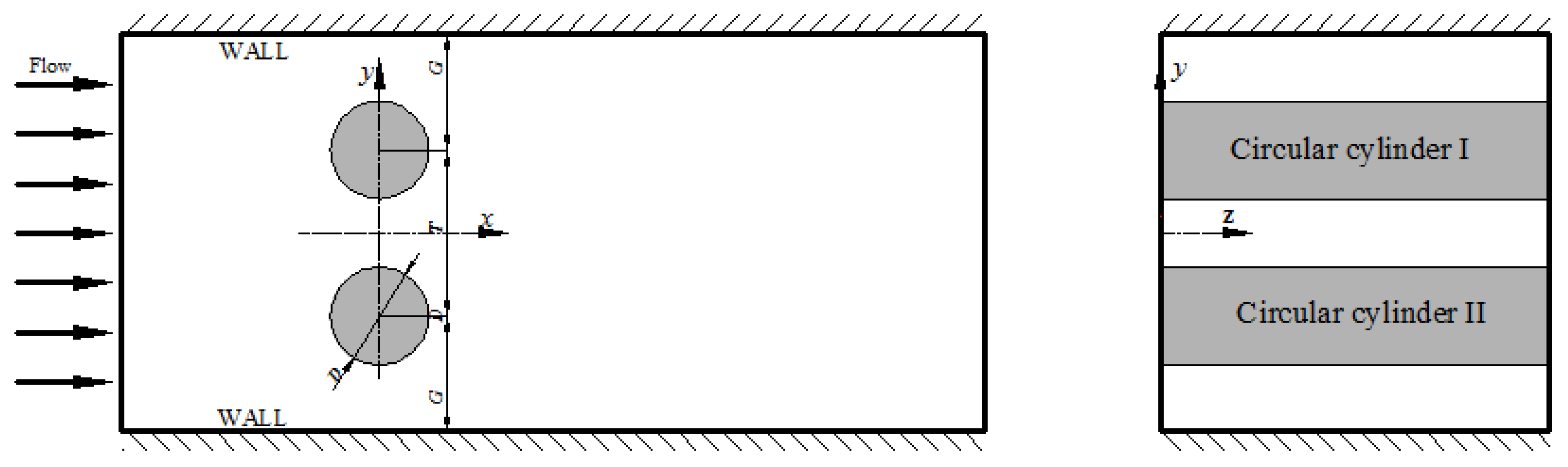
As shown in Figure 1, two side-by-side cylinders of equal diameter were placed between two parallel walls. The origin of the Cartesian coordinate system was located at the connection of two cylindrical centers at the still water level, and the x, y, and z axes were in the longitudinal, transverse and vertical directions, respectively. The non-dimensional cylindrical diameter is D; T represents the gap between the two cylindrical centers; the distance between the cylinder and the wall is defined as G. The computational domain extended 20D upstream and 40D downstream from the center of the cylinder; this ensured that the boundary had no effect on the flow field [13,23]. The height of the cylinder was 7D, and the water depth H was slightly lower than this height, so that the free surface was sufficiently developed.
The fluid is assumed to be incompressible and Newtonian, with density ρ and kinematic viscosity ν, flowing with a uniform inlet velocity U parallel to the channel wall. To investigate the wall proximity effects on flow field and the free surface characteristics, the distance between the cylinder and the wall was fixed to G/D = 8.0 for the first time; Meng et al. [24] used the size of G/D = 8.0 to simulate flow around a smooth circular cylinder for Re = 1.31 × 10⁴, which was sufficient to obtain results unaffected by the wall. Then, G/D was reduced to 1.0. The influence of gap flow between the two cylinders was also investigated for the gap-to-diameter ratios T/D = 1.25, 1.5, and 1.75. All cases were carried out at Re = 1.0 × 10⁴ as shown in Table 1; the non-dimensional parameter of Reynolds number Re is defined as in Equation (1).
2.2. Governing Equation and Solution Method
The continuity equation and three-dimensional unsteady Reynolds-averaged Navier–Stokes (URANS) equations were used as the governing equations.
where the operation is ensemble averaging; ui denotes the fluid velocity component in the streamwise (x) direction; along the centers of the two cylinders (y) and the depth of water (z), respectively. xi represents the different axes of the Cartesian coordinate system and p here is pressure. represents the kinematic viscosity coefficient.
The Reynolds stresses in Equation (3) are solved by Boussinesq’s formula (see Equation (4))
where and denote eddy viscosity and the Kronecker sign, respectively. Turbulence kinetic energy K and energy dissipation ɛ were solved by the RNG k-ɛ model.
The tracking of the free surface was accomplished by the volume-of-fluid method and complies with the mass conserving method. The volume fraction of the water was obtained from conservation Equation (5). The function F in Equation (5) is defined so that its value is in unity at any point occupied by the water and zero otherwise. The average value of F in a cell represents the volume fraction of water in the cell. In particular, a zero value of F corresponds to a cell with no fluid, and a unit value indicates that the cell is full of water. The value of F in a cell between zero and one must contain a portion of the free surface [20]. The isosurface of F = 0.5 is defined as the free surface location.
The spatial discretization of governing equations was based on the finite volume method (FVM), and all of the flow variables’ value is stored in cell centers. Its solution was obtained using the semi-implicit method for pressure-linked equations consistent (SIMPLEC), which was implemented by ANSYS Fluent (version 16.0, ANSYS Inc., Canonsburg, PA, USA). The second-order windward was used for computing convective flux, and the temporal discretization scheme was second-order implicit. The geometry reconstruction method was used to reconstruct the air–water interface. The RNG k-ɛ turbulence model was adapted to simulate the Reynolds stresses [25,26].
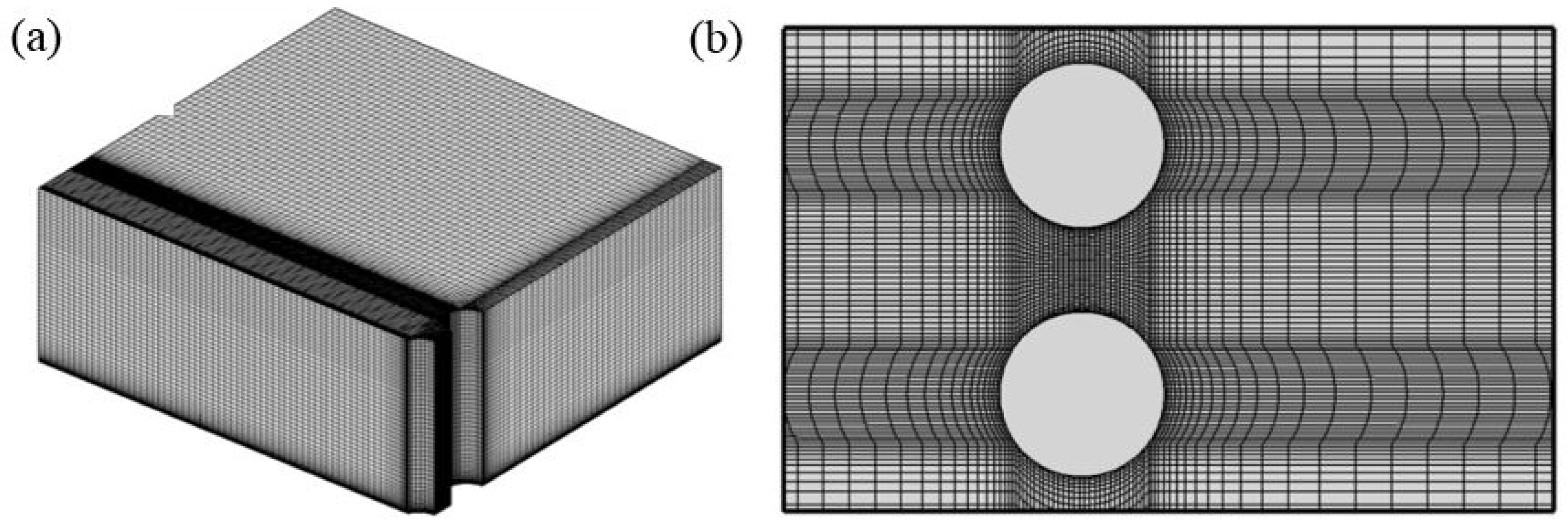
The mesh type and boundary conditions for all cases were the same. The hexahedral grid was adopted in the whole fluid region, as shown in Figure 2. The turbulent boundary layer region of wall contains a number of grid nodes, and the dimensionless distance y+ between the first layer of the grid node and the wall in boundary layer region meets the following requirements:
where y is the first cell center distance from the wall; ut denotes friction velocity.
The boundary conditions were defined as follows: (1) the inlet boundary is defined by a uniform flow velocity (ux = 0.45, uy = 0, uz = 0); turbulent intensity I is defined as in Equation (7), and was set to 0.4%; (2) the outlet boundary adopted a pressure outlet, which ensured the flow in upstream was not affected by the backflow; (3) the no-slip boundary condition was applied at the wall and the cylinder surface, respectively, where the pressure gradient is, n is the outward unit normal vector, and the velocity of flow is; and (4) the symmetrical boundary condition was applied to the top of the computational domain.
The computational domain was initially filled with water at rest, and then gradually accelerated. A steady state was achieved at about t = 3, which corresponded to about five vortex-shedding periods. The computations were continued until t = 200, with the time increment being 0.0005.
3. Results and Discussion
3.1. Validation of Numerical Model
The flow fields are not affected by the channel walls at G/D = 8.0. Thus, the cases where G/D = 8.0 were comparative to study the wall effects, and several numerical cases were carried out to verify the model at Re = 1.0 × 10⁴ for G = 8.0D, T/D = 1.75. Three types of values were used for comparison with the experimental and numerical results from the previous studies: (1) streamlines; (2) instantaneous span-wise vorticity distribution; and (3) the drag coefficient.
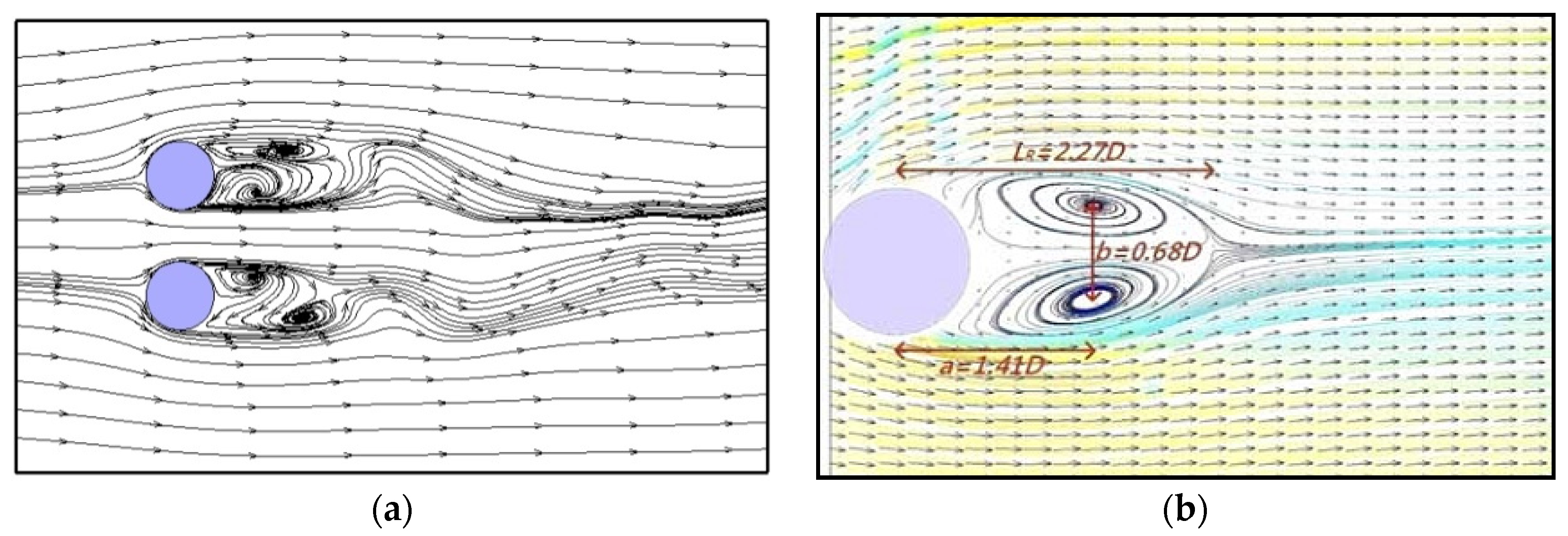
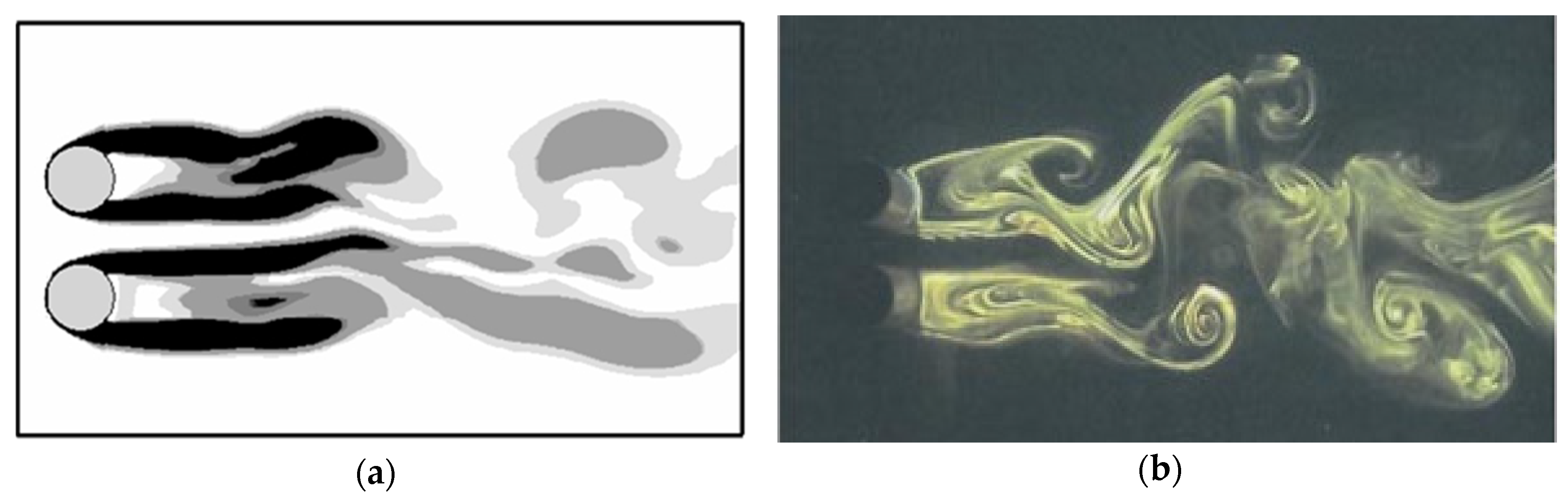
Figure 3 compares the streamline distribution obtained from the present model with that from Zhou’s experiments [27], where data was measured by particle image velocimetry (PIV) technology. It can be seen that the flow field away from the free surface was not disturbed by the gap flow, and a pair of vortexes in the wake of the two cylinders was observed, similar to the flow behind a cylinder. Figure 4 shows the instantaneous span-wise vorticity distribution, which was in accordance with the experimental results by Zhou et al. [28]. Therefore, the model could accurately simulate flow field characteristics of flow around two side-by-side circular cylinders.
In Table 2, the Strouhal number St, and mean drag coefficient CD obtained by the present model are presented; their dimensionless definitions are given in Equations (8) and (9). The table indicates that the CD and St values of the present numerical results were in good agreement with the experimental data by Earman et al. [29] and the numerical results from Jun et al. [30]. Furthermore, the errors of CD were less than 3% for G/D = 8.0, T/D = 1.5, and the Strouhal number was close to the constant value 0.2. To the best of our knowledge, no values of CD for T/D = 1.25 and 1.75 were numerically or experimentally presented in the previous works, and only our values are given.
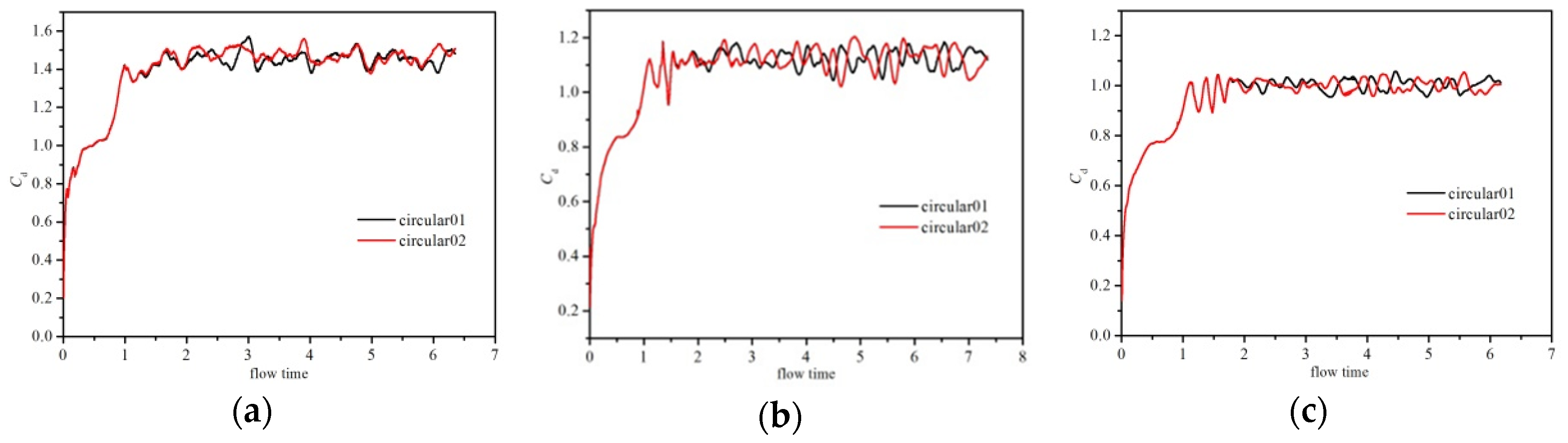
Table 2 also shows the calculated CD and St at G/D = 1.0 for various ratios T/D = 1.25, 1.5, and 1.75. The CD values of cylinder I and II were basically the same, and these values were smaller than at G/D = 8.0. Figure 5 displays the variation of the drag coefficient, their phases are opposite at distinct moments, resulting in drag force offset by each other.
where is along the x axis of drag force; is the undisturbed flow velocity; and is vortex shedding frequency.
3.2. Free Surface Characteristics
3.2.1. Free Surface Periodicity
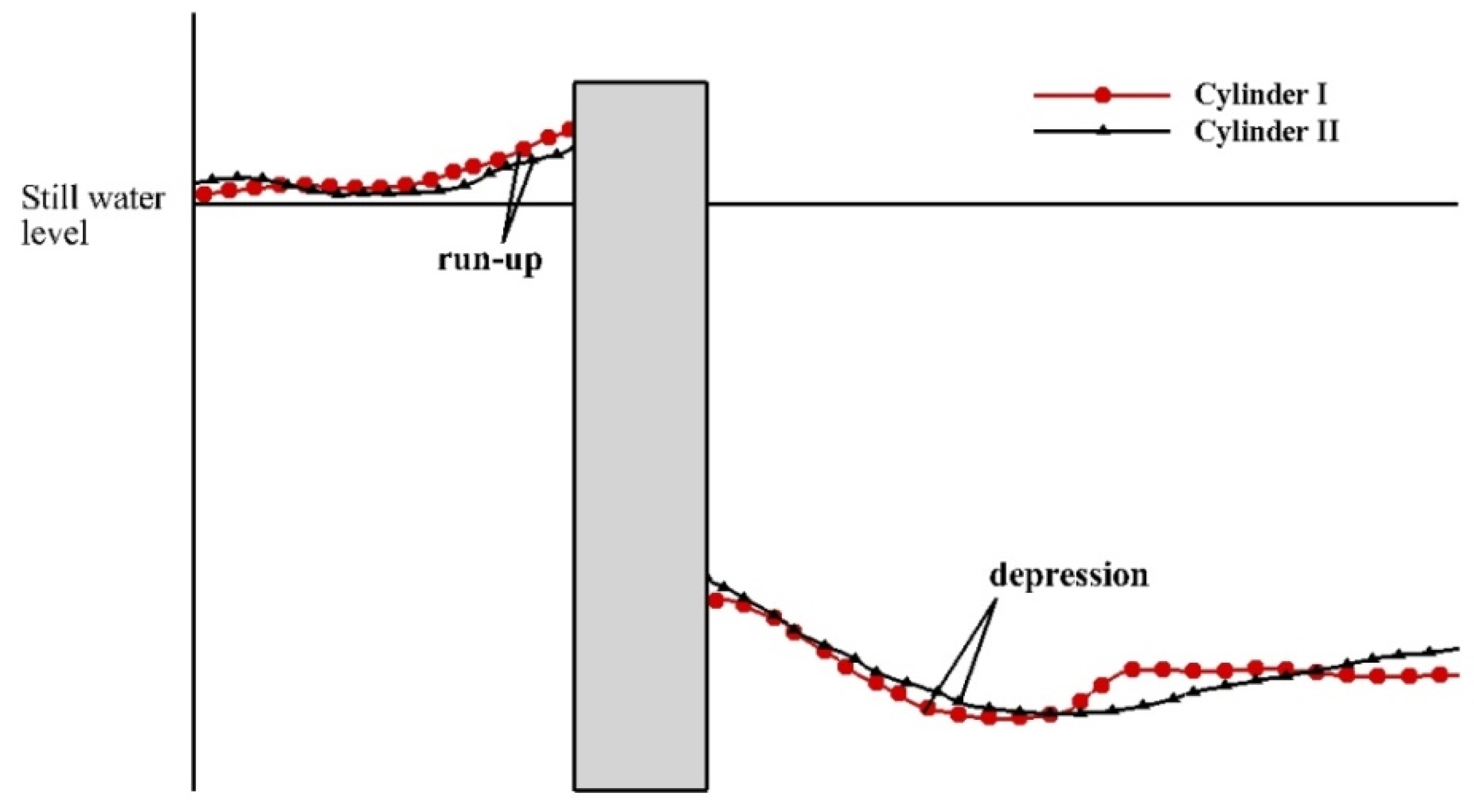
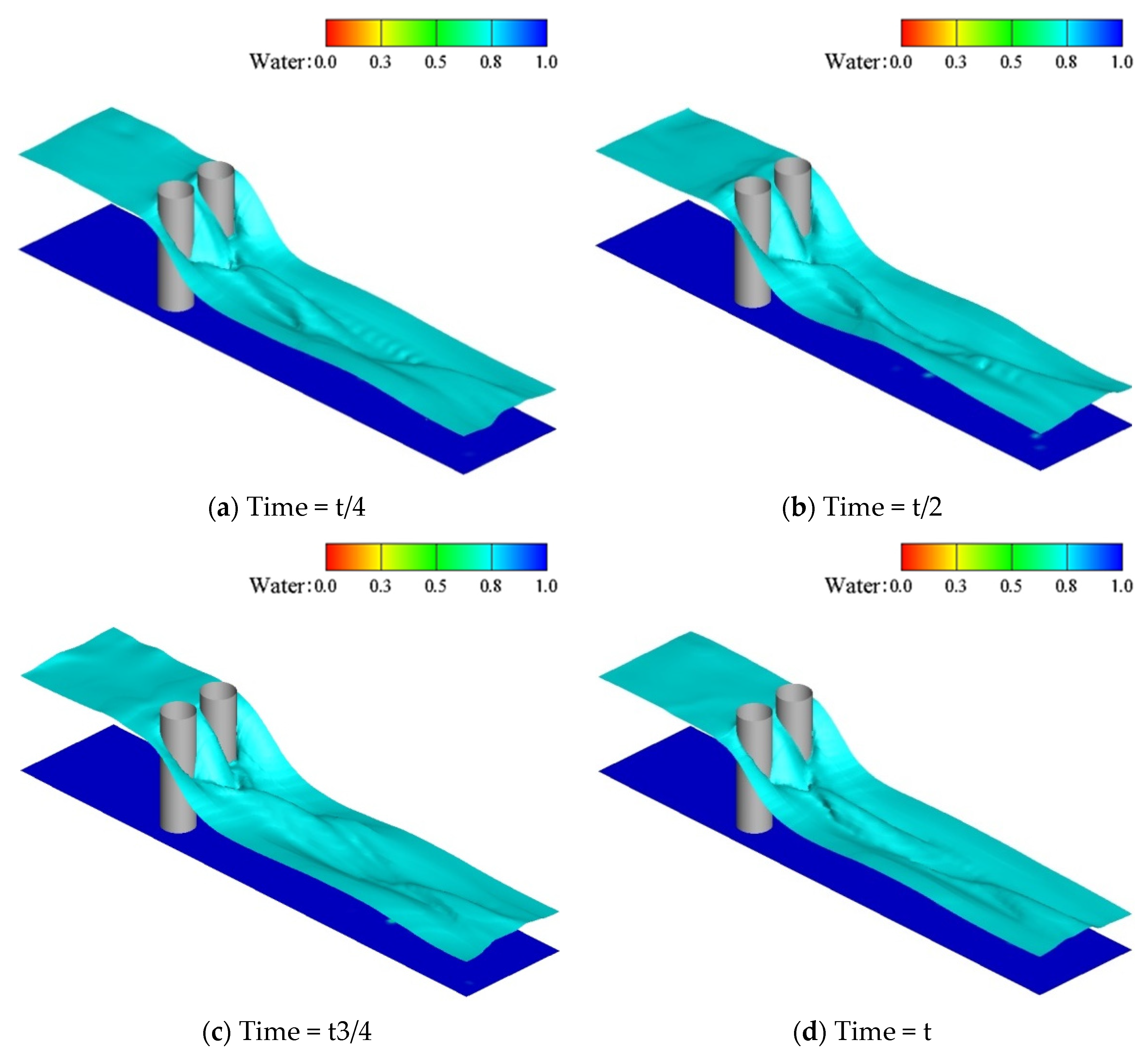
Through numerical simulations, it was found that the free surface is periodic in time scale. The evolution of the free surface in one period for G/D = 1.0 and T/D = 1.5 is discussed as a representative case; as shown in Figure 6 and Figure 7. Figure 6 is a schematic of the water level, showing the runup to the waterline in front of cylinders I and II, and the ‘depression’ of the maximum drawdown at the back of the cylinder. These features were also well observed in Hay’s experiment [31].
It can be seen from Figure 7 that the width of the flow area was reduced due to the cylinders, resulting in the difference between the surface elevation in the downstream and the upstream. The difference ΔH may, as an approximation, be defined as Equation (10).
where V, B, and H represent the velocity of the flow passing through the section, the width, and water depth of the channel without the cylinder, respectively; and denote the velocity and the width with the cylinder, respectively.
The free surface exhibits other variations in the vicinity of either of the two cylinders in Figure 7. There was also a ‘depression’ around the side edge of the cylinder, accompanied by a significant weak hydraulic jump. The two shares of weak jump and the gap flow rapidly converged within a short distance and formed a new single-strand hydraulic jump. The new hydraulic jump was deflected to the left or right wall within one period.
The characteristics of the free surface were similar within one period. Therefore, for the other cases, the free surface evolution of any specific time within one period was taken as the research object in the following section.
3.2.2. Effect of Gap Ratio on Free Surface
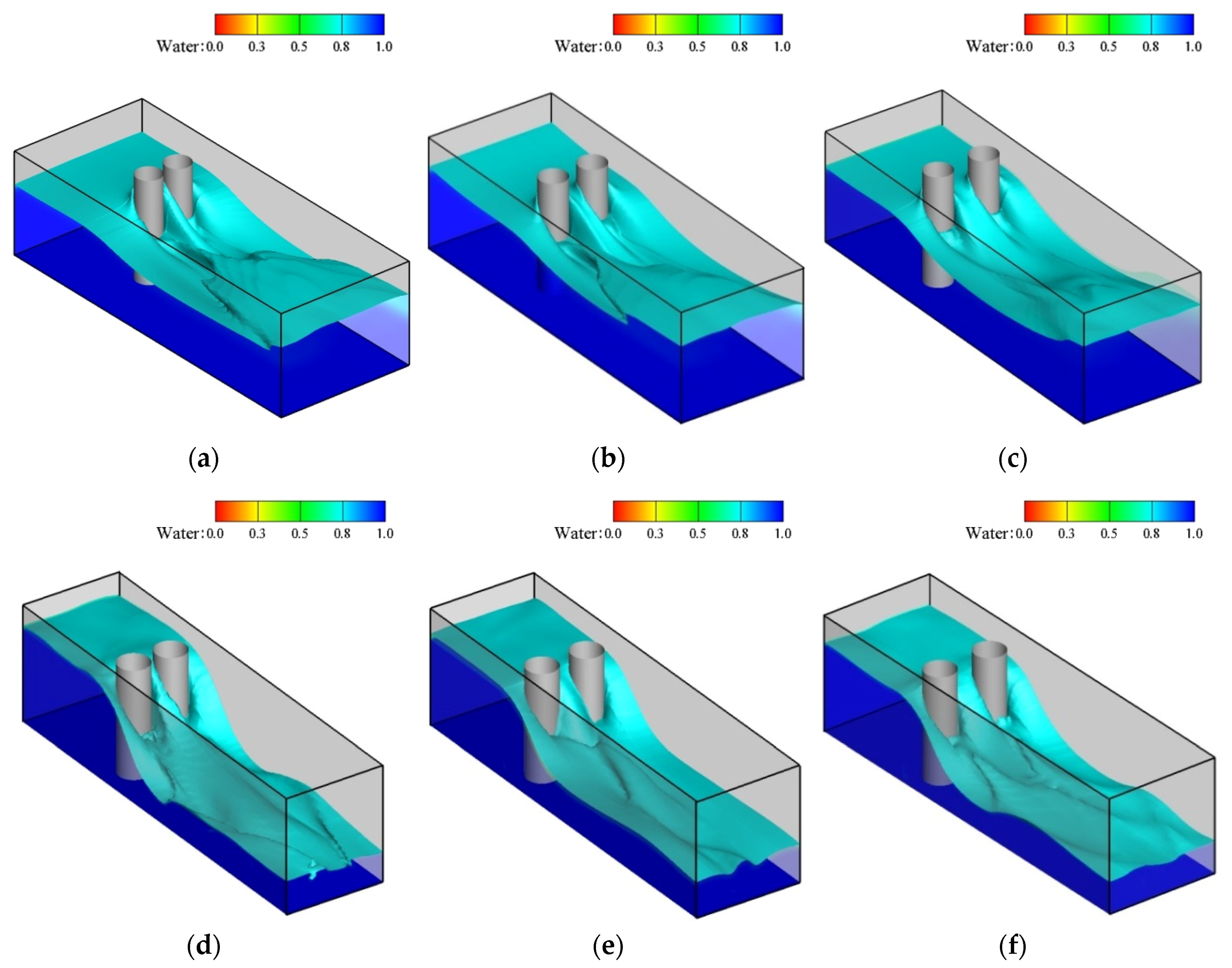
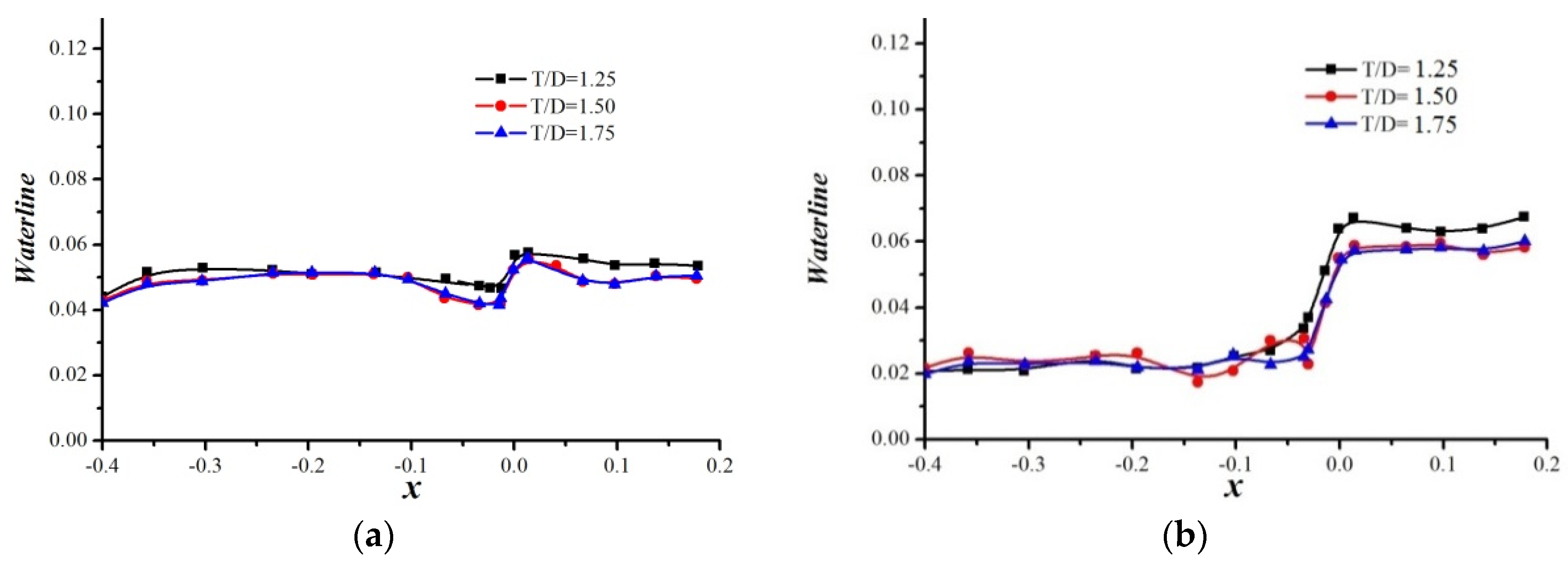
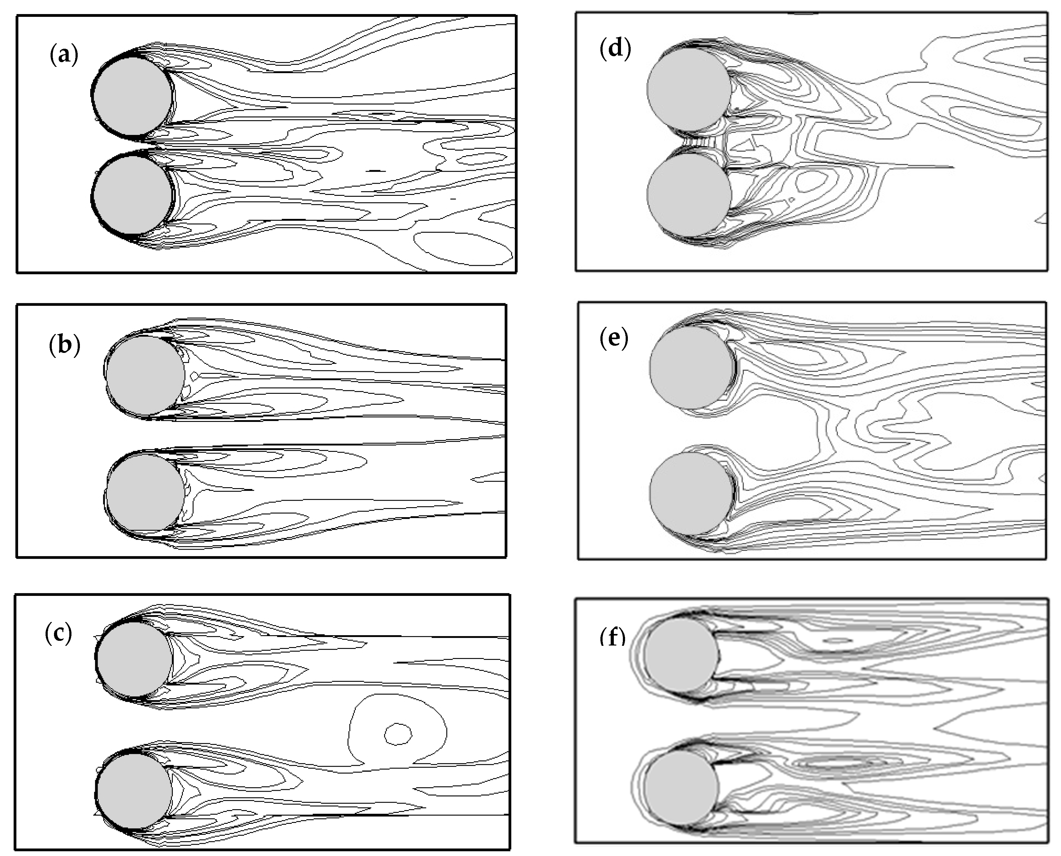
Figure 8a–c shows the characteristics of the free surface in the characteristic region for G/D = 8.0 at different gap ratios. It is clear from Figure 8a that the walls had no significant effect on the free surface. The following features were observed: there was a water level difference between the upstream and downstream; a depression was produced downstream, for which the distance from the center line of two cylinders was roughly equal as seen in Figure 9a; and a single strand weak hydraulic jump at the rear of a cylinder gradually spread downstream and was pushed outward by the gap flow between the two cylinders.
According to the evolution of weak hydraulic jump, the free surface in the wake flow could be defined in two patterns: in the cases of T/D = 1.25 and 1.5 (cases 4 and 5), the weak hydraulic jump independently developed and was deflected outwards by the gap flow, and then converged together when the jump was far away from the two cylinders; in the case of T/D = 1.75 (case 6), the jump developed independently.
The walls were then moved closer to the cylinders so that G/D = 1.0 to observe the effects of wall proximity, as shown in Figure 8d–f. A closer examination of the free surface near the two cylinders indicated that the flow between the wall and the cylinder was inwards deflected by the wall and interfered with the weak hydraulic jump in the wake flow. On the other hand, the interference of the wall and the extrapolation of the gap flow between the two cylinders made the profile of the free surface at T/D = 1.5 (case 2) different from T/D = 1.25 and 1.75 (cases 1 and 3). As the extrapolation effect was stronger than the wall effect for cases 1 and 3, the hydraulic jump developed independently, but the jump soon converged for case 2. In addition, the change in the water line and the depression behind the cylinder were also different than in the other cases, as seen in Figure 9b. Some common phenomena were also observed, such as a higher water level upstream, and a depression downstream.
The foregoing analysis showed that the influences of the gap decreased with increasing gap when the characteristics of the free surface were not affected by the wall. The gap and the wall influence the free surface when affected by the wall, depending on which of them was dominant.
3.3. Flow Characteristics
3.3.1. Vortex Shedding along the Water Depth
The variation in the vortex shedding pattern along the water depth is presented in Figure 10 to investigate the influence of the free surface on the vortex shedding from side-by-side cylinders at G/D = 8.0 and T/D = 1.75. The solution for flow past two side-by-side cylinders at T/D = 1.8 by Liu et al. [32] is provided for comparison.
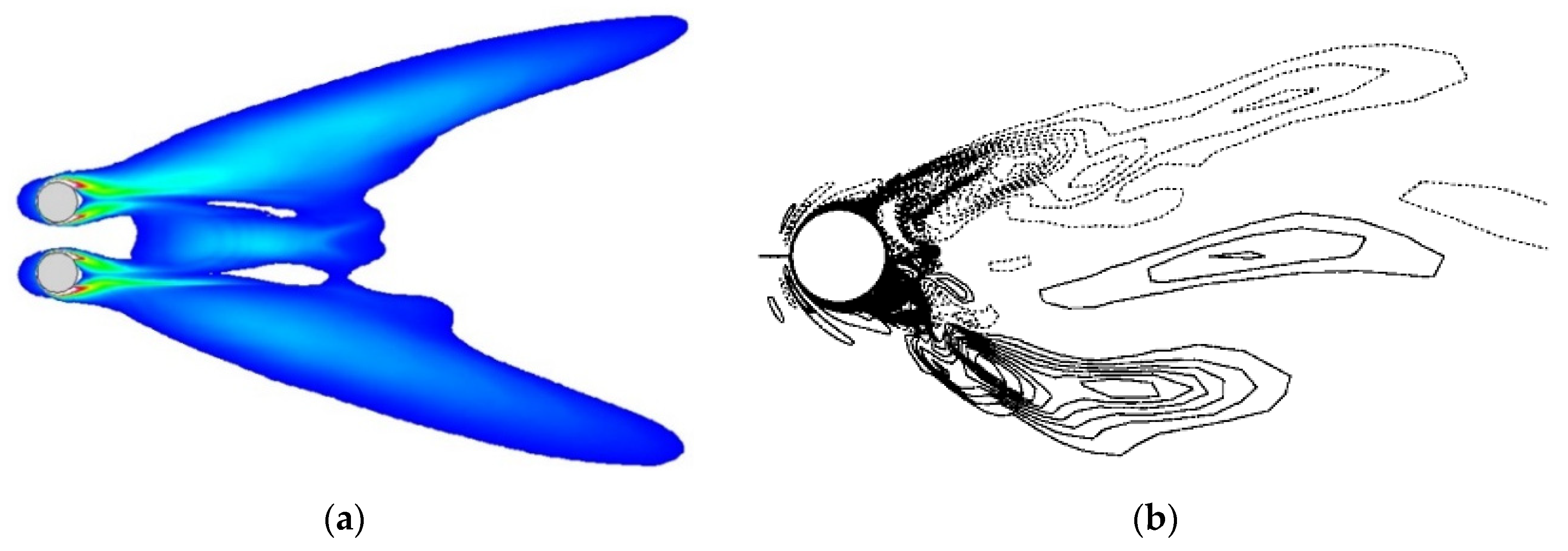
In Figure 10a, an instantaneous vorticity on the free surface was compared to the result of a single cylinder, which was obtained by Kawamura et al. [8] in a large eddy simulation. It can be seen that the gap flow suppressed the shedding vortex on the free surface near the cylinder. In addition, the vortices shed from the inner side of the two cylinders were taken away by the gap flow and constituted a new large vortex in the downstream. The vortices from the outer side of the cylinders were deflected outward.
Figure 10c–e show that the instantaneous vortex was affected by the free surface at different depths. At Z = 0.031 and Z = 0.03, the new large vortex near the gap became weakened, and the deflection of the gap flow disappeared. Near the bottom at Z = 0.022, the vortex shedding was not disturbed by the free surface, and a Karman vortex street, as in the flow around a single cylinder, was observed [17,33].
3.3.2. Flow Structures
It is well known that gap ratios have a significant impact on the flow characteristics. Chen et al. [17] and Senlin et al. [34] divided the gap ratio between two cylinders into three categories: (1) the small spacing ratio; (2) the intermediate spacing ratio; and (3) the large spacing ratio. In the present paper, a similar classification was adopted to describe the relationship between the flow characteristics and spacing ratios. The spacing ratios used in this paper all belong under small gap ratios.
Combined with the results and discussion of the free surface and vortex shedding above, the flow pattern was defined into two types at different ratios: (1) the single bluff-body behavior, and (2) the asymmetric or symmetric biased flow. To discuss the effect of the free surface on vorticity patterns in the wake flow region, Figure 11 shows the contours of instantaneous spanwise vorticity near the free surface for G/D = 8.0 and 1.0.
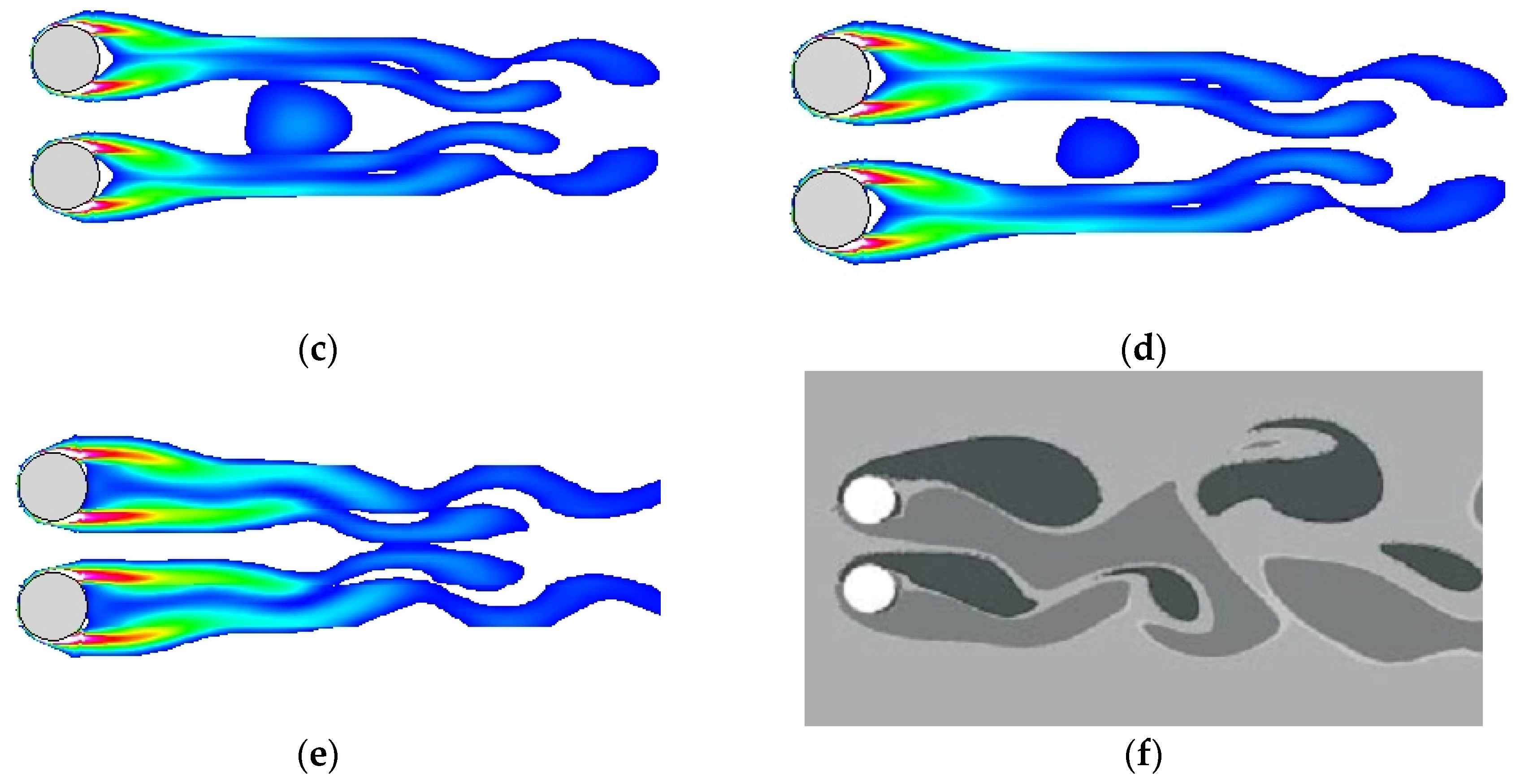
We first focused on flow structures at G/D = 8.0 with varying longitudinal separation between the two cylinders. It can be seen from Figure 10 that the wall had no significant effect on the vorticity field near the cylinder. The boundary layer began to separate from the upper half of the cylinder, which is consistent with the boundary layer separation law. The vortex shedding behind the cylinder occurred in pairs. The wake patterns showed a single bluff body behavior. Due to the gap flow’s interference, the vortex shedding from the side near the cylindrical wall was pushed outwards at different gap ratios T/D. At the large ratio T/D = 1.75, the effect of pushing outward was more obvious.
In the case of G/D = 1.0, the vortex shedding from the outer side of the cylinder was strongly deflected to the other side due to the influence of the wall. Moreover, the outer push of the gap flow caused the vortex shedding from the side near the cylindrical wall to be suppressed at T/D = 1.25 and 1.5 (cases 1 and 2) and was taken away by the vortex formed by the gap flow. In particular, for the case T/D = 1.5 (case 2), the phenomenon was more pronounced. However, the deflection of the gap flow decreased at T/D = 1.75 (case 3); when G/D = 1.0, the vortex shedding pattern also manifested itself as single bluff body behavior.
4. Conclusions
Turbulent flow around two side-by-side equal diameter cylinders at Re = 1.0 × 10⁴ was investigated by solving the URANS equations together with the RNG k-ɛ model and the VOF method for free surface modeling. Previous research of the free surface has seldom provided three-dimensional characteristics in two side-by-side cylinder cases. Here, a deeper understanding of the characteristics of the free surface and the computational method was proven through a comparison with other experimental data and numerical results.
The computational results were generally in good agreement with the experimental results of Hay and Kawamura with respect to the free surface characteristics [8,31]. The shape of the free surface was characterized by the runup on the upstream side of a cylinder and the water level difference between the downstream and upstream. There was a ‘depression’ around the side edge and at the back of the cylinder. On the other hand, the maximum drawdown of the water level was located behind the cylinder. In addition, the variation of free surface was periodicity. The weak hydraulic jump was captured in the downstream.
The flow near the two cylinders was pushed outwards and the flow between the cylinder and the wall was pushed inwards, which affected the evolution of the weak hydraulic jump in the wake flow. For the cases of G/D = 1.0, the extrapolation effect of the gap flow at T/D = 1.25 and 1.75 was stronger than the wall proximity effects, resulting in the jump being independently developed. In contrast, they quickly converged at G/D = 1.0 and T/D = 1.5. However, the flow was not affected by the wall (G/D = 8.0); the extrapolation effect decreased with the increasing gap.
The computational results also suggested that the vortex structure on and near the free surface correlated closely with the free surface. The vortex patterns near the free surface would be a variety in the wake region: (1) single bluff-body behavior; and (2) asymmetric or symmetric biased flow.
Author Contributions
Conceptualization: D.L. and G.D.; Methodology: Q.Y.; Software, D.L.; Validation: D.L., Q.Y. and X.M.; Formal Analysis: G.D.; Investigation: D.L.; Resources: Q.Y.; Data Curation: X.M.; Writing—Original Draft Preparation: D.L.; Writing—Review and Editing: X.M.; Visualization: Q.Y.; Supervision: Q.Y.; Project Administration: Q.Y.; and Funding Acquisition: G.D.
Funding
This research received no external funding.
Acknowledgments
This work thanks Xin Jin and Haomiao Sun for their help and guidance. The authors would like to thank the anonymous reviewers and the editors for their comments.
Conflicts of Interest
The authors declare no conflict of interest.
References
- Bhattacharyya, S.; Dhinakaran, S. Vortex shedding in shear flow past tandem square cylinders in the vicinity of a plane wall. J. Fluids Struct. 2008, 24, 400–417. [Google Scholar] [CrossRef]
- An, H.; Cheng, L.; Zhao, M. Steady streaming around a circular cylinder near a plane boundary due to oscillatory flow. J. Hydraul. Eng. 2011, 13, 23–33. [Google Scholar] [CrossRef]
- Li, S.; Ni, B.Y. Simulation on the interaction between multiple bubbles and free surface with viscous effects. Eng. Anal. Bound. Elem. 2016, 68, 63–74. [Google Scholar] [CrossRef]
- Cruchaga, M.; Battaglia, L.; Storti, M.; D’Elía, J. Numerical Modeling and Experimental Validation of Free Surface Flow Problems. Arch. Comput. Methods Eng. 2016, 23, 139–169. [Google Scholar] [CrossRef]
- Lee, S.J. Flow past a circular cylinder over a free surface: Interaction between the near wake and the free surface deformation. J. Fluids Struct. 2004, 19, 1049–1059. [Google Scholar] [CrossRef]
- Chaplin, J.R.; Teigen, P. Steady flow past a vertical surface-piercing circular cylinder. J. Fluids Struct. 2003, 18, 271–285. [Google Scholar] [CrossRef]
- Reichi, P.; Hourigan, K.; Thompson, M.C. Flow past a cylinder close to a free surface. Flow past a cylinder close to a free surface. J. Fluid Mech. 2005, 533, 269–296. [Google Scholar]
- Kawamura, T.; Mayer, S.; Garapon, A.; Sørensen, L. Large Eddy Simulation of a flow past a free surface piercing circular cylinder. J. Fluids Eng. 2002, 124, 91–101. [Google Scholar] [CrossRef]
- Zovatto, L.; Pedrizzettif, G. Flow about a circular cylinder between parallel walls. J. Fluid Mech. 2001, 440, 1–25. [Google Scholar] [CrossRef]
- Chakraborty, J.; Verma, N.; Chhabra, R.P. Wall effects in flow past a circular cylinder in a plane channel: A numerical study. Chem. Eng. Process. 2004, 43, 1529–1537. [Google Scholar] [CrossRef]
- Sintu, S.; Sinhamahapatra, K.P. Flow past a circular cylinder between parallel walls at low Reynolds numbers. Ocean Eng. 2010, 37, 757–769. [Google Scholar]
- D’Souza, J.E.; Jaiman, R.K.; Mak, C.K. Dynamics of tandem cylinders in the vicinity of a plane moving wall. Comput. Fluids 2016, 124, 117–135. [Google Scholar] [CrossRef]
- Kumarasamy, S.; Barlow, J.B. Computation of unsteady flow over a half cylinder close to a moving wall. J. Wind Eng. Ind. Aerodyn. 1997, 69–71, 239–248. [Google Scholar] [CrossRef]
- Kim, S.; Alam, M.M. Characteristics and suppression of flow-induced vibrations of two side-by-side circular cylinders. J. Fluids Struct. 2015, 54, 629–642. [Google Scholar] [CrossRef]
- Gopalan, H.; Jaiman, R. Numerical study of the flow interference between tandem cylinders employing non-linear hybrid URANS–LES methods. J. Wind Eng. Ind. Aerodyn. 2015, 142, 111–129. [Google Scholar] [CrossRef]
- Bensedira, S.; Abdellah el-hadj, A.; Semmar, D.; Ait Messaouden, N. Dynamic analysis of flow around two Side-by-Side cylinders near a wall. Arab. J. Sci. Eng. 2017, 2, 1–10. [Google Scholar] [CrossRef]
- Chen, L.; Tu, J.Y.; Yeoh, G.H. Numerical simulation of turbulent wake flows behind two side-by-side cylinders. J. Fluids Struct. 2003, 18, 387–483. [Google Scholar] [CrossRef]
- Williamson, C.H.K. Evolution of a single wake behind a pair of bluff bodies. J. Fluid Mech. 1985, 159, 1–18. [Google Scholar] [CrossRef]
- Sumner, D.; Wong, S.S.T.; Price, S.J.; Paidoussis, M.P. Fluid behavior of side-by-side circular cylinders in steady cross-flow. J. Fluids Struct. 1999, 13, 309–338. [Google Scholar] [CrossRef]
- Hirt, C.W.; Nichols, B.D. Volume of Fluid (VOF) Method for the dynamics of free boundaries. J. Comput. Phys. 1981, 39, 201–225. [Google Scholar] [CrossRef]
- Soh, G.Y.; Yeoh, G.H.; Timchenko, V. Improved volume-of-fluid (VOF) model for predictions of velocity fields and droplet lengths in microchannels. Flow Meas. Instrum. 2016, 51, 105–115. [Google Scholar] [CrossRef]
- Reddy, R.; Banerjee, R. GPU accelerated VOF based multiphase flow solver and its application to sprays. Comput. Fluids 2015, 117, 287–303. [Google Scholar] [CrossRef]
- Farrant, T.; Tan, M.; Price, W.G. A cell boundary element method applied to laminar vortex-shedding from arrays of cylinders in various arrangements. J. Fluids Struct. 2000, 14, 375–402. [Google Scholar] [CrossRef]
- YuLin, M.; ZhenLiao, G. Vortex shedding around a near-wall circular cylinder induced by a solitary wave. J. Fluids Struct. 2015, 58, 127–151. [Google Scholar]
- Stringer, R.M.; Zang, J.; Hillis, A.J. Unsteady RANS computations of flow around a circular cylinder for a wide range of Reynolds numbers. Ocean Eng. 2014, 87, 1–9. [Google Scholar] [CrossRef] [Green Version]
- Pope, S.B. Turbulent Flows; Cambridge University Press: Cambridge, UK, 2000. [Google Scholar]
- Zhou, B.; Wang, X.; Guo, W.; Gho, W.M.; Tan, S.K. Experimental study on flow past a circular cylinder with rough surface. Ocean Eng. 2015, 109, 7–13. [Google Scholar] [CrossRef]
- Zhou, Y.; Wang, Z.J.; So, R.M.C.; Xu, S.J.; Jin, W. Free vibrations of two side-by-side cylinders in a cross-flow. J. Fluid Mech. 2001, 443, 197–229. [Google Scholar] [CrossRef] [Green Version]
- Bearman, P.W.; Wadcock, A.J. The interaction between a pair of circular cylinder normal to a stream. J. Fluid Mech. 1973, 61, 499–512. [Google Scholar] [CrossRef]
- Jun, L.; Sirui, J. Numerical simulation of flow around two cylinders at high Reynolds number. J. Hydrodyn. 2001, 16, 101–109. [Google Scholar]
- Hay, A.D. Flow about Semi-Submerged Cylinders of Finite Length; Princeton University Report; Princeton University: Princeton, NJ, USA, 1947. [Google Scholar]
- Liu, Y.; So, R.M.C.; Lau, Y.L.; Zhou, Y. Numerical studies of two side-by-side elastic cylinders in a cross-flow. J. Fluids Struct. 2001, 15, 1009–1030. [Google Scholar] [CrossRef]
- Wang, X.K.; Zhang, J.X.; Hao, Z.; Zhou, B.; Tan, S.K. Influence of wall proximity on flow around two tandem circular cylinders. Ocean Eng. 2015, 94, 36–50. [Google Scholar] [CrossRef]
- Zheng, S.; Zhang, W.; Lv, X. Numerical simulation of cross-flow around three equal diameter cylinders in an equilateral-triangular configuration at low Reynolds numbers. Comput. Fluids 2016, 130, 94–108. [Google Scholar] [CrossRef]
Figure 1.
Schematics of flow around two side-by-side cylinders.

Figure 2.
Grid used for the simulations at two positions: (a) part of the upstream computational domain, and (b) near the two cylinders.
Figure 2.
Grid used for the simulations at two positions: (a) part of the upstream computational domain, and (b) near the two cylinders.

Figure 3.
Streamline distribution. (a) T/D = 1.75, G/D = 8.0, (b) The particle image velocimetry (PIV) results at Re = 17,980 (Zhou et al., 2015. [27]).
Figure 3.
Streamline distribution. (a) T/D = 1.75, G/D = 8.0, (b) The particle image velocimetry (PIV) results at Re = 17,980 (Zhou et al., 2015. [27]).

Figure 4.
Instantaneous span-wise vorticity distributions. (a) T/D = 1.75, G/D = 8.0, (b) The results of PIV, T/D = 1.80 (Zhou et al., 2001. [28]).
Figure 4.
Instantaneous span-wise vorticity distributions. (a) T/D = 1.75, G/D = 8.0, (b) The results of PIV, T/D = 1.80 (Zhou et al., 2001. [28]).

Figure 5.
The drag coefficient for G/D = 1.0. (a) T/D = 1.25; (b) T/D = 1.5; and (c) T/D = 1.75.

Figure 6.
The schematic of the water level for G/D = 1.0 and T/D = 1.50.

Figure 7.
Evolution of free surface within one period at T/D = 1.5, G/D = 1.0. (a,b) are the shape of free face in 1/4 period and 1/2 period, (c,d) are in 3/4 period and the last moment.
Figure 7.
Evolution of free surface within one period at T/D = 1.5, G/D = 1.0. (a,b) are the shape of free face in 1/4 period and 1/2 period, (c,d) are in 3/4 period and the last moment.

Figure 8.
Free-surface shape at different gap ratios: T/D = 1.25, 1.50, and 1.75. The distances between the cylinder and side wall are 8.0D (a–c) and 1.0D (d–f).
Figure 8.
Free-surface shape at different gap ratios: T/D = 1.25, 1.50, and 1.75. The distances between the cylinder and side wall are 8.0D (a–c) and 1.0D (d–f).

Figure 9.
The water level along the central axis (y = 0). (a) G/D = 8.0, (b) G/D = 1.0.

Figure 10.
Development of vortex shedding at G/D = 8.0 and T/D = 1.75: (a) on the free surface; (b) instantaneous vorticity on a free surface of a single cylinder (Kawamura et al., 2002); (c) Z = 0.031; (d) Z = 0.03; (e) Z = 0.022; and (f) vortex formation of two rigid cylinders for T/D = 1.80 (Liu et al., 2001).


Figure 11.
Vortex shedding at G/D = 8.0 is not affected by the walls for the gap ratios: (a) T/D = 1.25; (b) T/D = 1.5; and (c) T/D = 1.75. Vortex shedding is affected at G/D=1.0 for the gap ratios: (d), T/D = 1.25; (e) T/D = 1.5; (f) T/D = 1.75.
Figure 11.
Vortex shedding at G/D = 8.0 is not affected by the walls for the gap ratios: (a) T/D = 1.25; (b) T/D = 1.5; and (c) T/D = 1.75. Vortex shedding is affected at G/D=1.0 for the gap ratios: (d), T/D = 1.25; (e) T/D = 1.5; (f) T/D = 1.75.


Table 1.
Simulation cases for flow over two side-by-side cylinders. Re: Reynolds number.
| Index | G/D | T/D | Re |
|---|---|---|---|
| Case 1 | 1.0 | 1.25 | 1.0 × 10⁴ |
| Case 2 | 1.0 | 1. 50 | 1.0 × 10⁴ |
| Case 3 | 1.0 | 1.75 | 1.0 × 10⁴ |
| Case 4 | 8.0 | 1.25 | 1.0 × 10⁴ |
| Case 5 | 8.0 | 1. 50 | 1.0 × 10⁴ |
| Case 6 | 8.0 | 1.75 | 1.0 × 10⁴ |
Table 2.
Aerodynamic coefficients compared with other results. St: Strouhal number; CD: drag coefficient.
Table 2.
Aerodynamic coefficients compared with other results. St: Strouhal number; CD: drag coefficient.
| T/D | Earman et al. (1973, Exp) | Liao Jun et al. (2001, Num) | G/D = 1.0 | G/D = 8.0 | ||||||||||
|---|---|---|---|---|---|---|---|---|---|---|---|---|---|---|
| CD | St | CD1 | CD2 | St1 | St2 | CD1 | CD2 | St1 | St2 | CD1 | CD2 | St1 | St2 | |
| 1.25 | 1.42 | 1.43 | 0.12 | 0.12 | 1.40 | 1.41 | 0.18 | 0.18 | ||||||
| 1.50 | 1.29 | 0.20 | 1.36 | 1.32 | - | - | 1.12 | 1.12 | 0.19 | 0.19 | 1.32 | 1.34 | 0.20 | 0.20 |
| 1.75 | 1.00 | 0.99 | 0.20 | 0.20 | 1.25 | 1.27 | 0.21 | 0.21 | ||||||
© 2018 by the authors. Licensee MDPI, Basel, Switzerland. This article is an open access article distributed under the terms and conditions of the Creative Commons Attribution (CC BY) license (http://creativecommons.org/licenses/by/4.0/).
Share and Cite
MDPI and ACS Style
Li, D.; Yang, Q.; Ma, X.; Dai, G. Free Surface Characteristics of Flow around Two Side-by-Side Circular Cylinders. J. Mar. Sci. Eng. 2018, 6, 75. https://0-doi-org.brum.beds.ac.uk/10.3390/jmse6030075
AMA Style
Li D, Yang Q, Ma X, Dai G. Free Surface Characteristics of Flow around Two Side-by-Side Circular Cylinders. Journal of Marine Science and Engineering. 2018; 6(3):75. https://0-doi-org.brum.beds.ac.uk/10.3390/jmse6030075
Chicago/Turabian StyleLi, Dengsong, Qing Yang, Xudong Ma, and Guangqing Dai. 2018. "Free Surface Characteristics of Flow around Two Side-by-Side Circular Cylinders" Journal of Marine Science and Engineering 6, no. 3: 75. https://0-doi-org.brum.beds.ac.uk/10.3390/jmse6030075
Note that from the first issue of 2016, this journal uses article numbers instead of page numbers. See further details here.