1. Introduction
Uplift and erosion of the northern margin of the Yilgarn Craton over between 2.7 and 2.2 Ga resulted in a low relief landscape, similar to the present, underlain by granitic rocks and minor greenstone belts that were deeply weathered to more than 200 m in places. Subsidence of the craton to an elevation probably less than 10 m above the contemporary sea level was followed by a marine transgression at ca 2.20 Ga that removed the soil cover and eroded a wave-cut surface on the deep saprolite.
Large blocks and boulders (up to 40 × 27 × 6 m
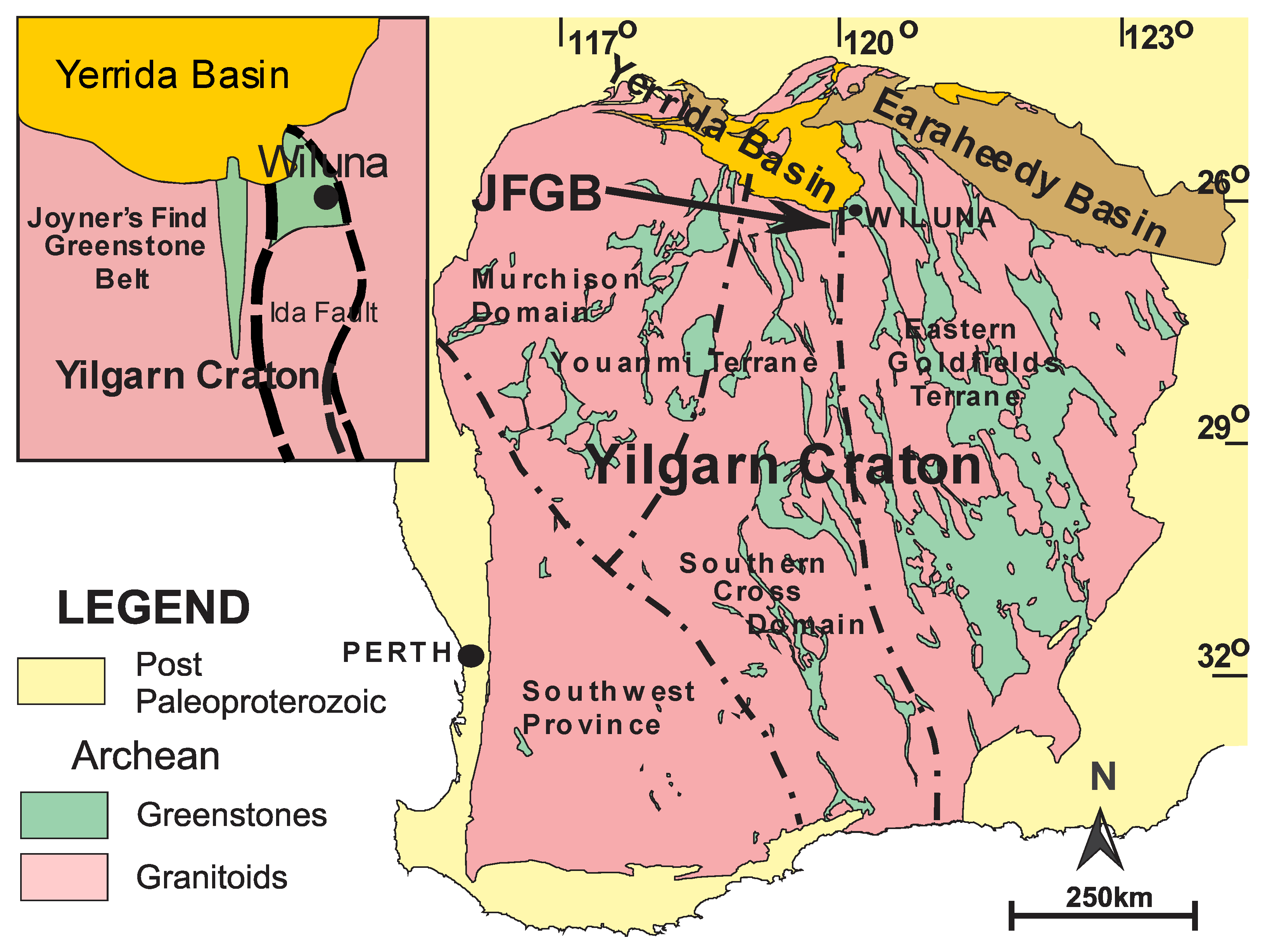
3) of banded iron formation (BIF) and massive hematite are exposed in a 300 m wide band stretching nearly three kilometres within the Joiner’s Find greenstone belt, northern Yilgarn Craton, Western Australia (
Figure 1). The blocks rest directly on a marine erosion surface formed during the marine transgression at 2.20 Ga [
1] on ultramafic rocks of the Archean Meekatharra Formation [
2,
3] prior to deposition of the Paleoproterozoic Windplain Group. The nearest outcrop of BIF lies in a north–south trending west-facing sub-vertical outcrop 900 m to the west of the blocks. A polymict conglomerate consisting of <15 cm diameter BIF, hematite, and minor goethitized mafic pebbles in a quartz sand matrix lies to the west of the Archean Wilgie Mia Formation BIF outcrop. It has been scoured from the surface of the BIF and the unconformity to the east but is also present on the eastern side of the largest blocks. The blocks and boulders are surrounded and overlain by epicontinental marine sedimentary rocks of the Windplain Group.
The BIF units of the Wilgie Mia Formation form a north–south trending flat-topped ridge (C Ridge) on which the wave-cut surfaces are well preserved. The central part of the Yaloginda Formation also forms a narrow flat-topped ridge (B Ridge), but the wave-cut surfaces are less clearly defined due to the thinness of the BIF/massive hematite units. The upper and lower parts of the Yaloginda Formation consist mainly of mafic amphibolite and generally underlie slopes on either side of the ridge interrupted by resistant outcrops of thin BIF and granular iron formation (GIF) units. Parts of the Murrouli Basalt and other amphibolite outcrops are strongly goethitized and form resistant outcrops above the surrounding land surface.
All sloping surfaces in the Joyner’s Find greenstone belt (JFGB) consist of pediments eroded on the saprolite and are overlain by a <30 cm thick cover of colluvium with numerous exposures of the underlying saprolite.
In the absence of any other reasonable model for the transportation and deposition of the large blocks, it is hypothesized that an exceptionally large tsunami generated by an oceanic asteroid impact was responsible.
2. Methods and Materials
The stratigraphy of the JFGB (
Table 1) was interpreted from detailed outcrop mapping with GPS locations of outcrops plotted at 1:2000 scale with units named initially after the magnetic highs; A–D from east to west. The similarity with the stratigraphy described by [
4] for the north-eastern Murchison Domain suggested these stratigraphic names be adopted informally for the JFGB [
2,
3].
The outlines of the exposed transported blocks were initially plotted by GPS and later measured using a 50 metre tape (
Table 2). The longest surface exposure was considered the A axis and the greatest width the C axis. B and D axes represent the shorter sides of trapezoidal blocks.
We based calculations of tsunami height and velocity on the modified equations proposed by [
5] for predicting the minimum flow velocity (and hence minimum wave height) required to initiate boulder transport under high-energy tsunami events, which builds on the theoretical framework originally developed by [
6,
7]. Given the largest boulders constrain a lower limit on the size of the tsunami [
8,
9], we specifically investigated the minimum velocity
Umin required to move the slabs of length
l = 40 m, width
w = 27 m, and thickness
t = 4 m over a distance of 900 m (i.e., corresponding to boulder #33 in
Table 2). We assume a BIF boulder density
ρs = 2800 kg m
−3, (average measured value of numerous samples of silicified weathered BIF from drill core), a seawater density
ρw = 1020 kg m
−3, and standard values for boulder drag and lift coefficients (
Cd = 1.95 and
Cl = 0.18, respectively) [
5]. Given that the original state of the boulder sources is unknown, we consider two scenarios: (1) the boulders were initially fully detached, or (2) they were joint-bounded in situ. The minimum velocities for each are thus
for the exposed and joint-bounded scenarios, respectively, such that in both cases
Umin~30 m s
−1.
Numerous determinations of the density of the strongly weathered and silicified BIF and the massive hematite were carried out on diamond drill core, including downhole geophysics, by Golden West Resources Ltd., as part of their ore deposit reserve measurements. The final densities used in their calculations were 2.8 for weathered BIF and 4.2 for massive hematite.
3. Results
The Joyner’s Find greenstone belt (JFGB) is an elongated outcrop of Archean supracrustal rocks, 42.5 km long with 10 km maximum width, extending south from the northern margin of the Yilgarn Craton, 30 km to the west of the township of Wiluna, 900 km northeast of Perth in Western Australia (
Figure 1). The JFGB contains a ~2.82–2.7 Ga [
10,
11] sub-vertical west-facing sequence of mainly mafic to ultramafic amphibolite interbedded with two sequences of banded iron formation (BIF) passing up into siliciclastic meta-sedimentary rocks (
Figure 2). The stratigraphy of the JFGB was interpreted from detailed outcrop mapping with GPS locations plotted at 1:2000 scale with units named initially after the magnetic highs—A–D from east to west. The similarity with the stratigraphy described by Van Kranendonk and Ivanic [
4] for the north-eastern Murchison Domain suggested those stratigraphic names to be adopted informally for the JFGB [
2,
3]. The greenstone belt is surrounded by monzogranite on three sides and is unconformably overlain by polymict conglomerate and sandstone of the Paleoproterozoic Windplain Group in the north (
Table 1). Numerous schistose northerly trending shear zones, 0.10–5 m wide, occur throughout the JFGB and are typically marked by bands of chlorite or mica schist. The mica schist bands in the surrounding monzogranite, together with granitized sediments, were previously interpreted as granite gneiss [
10,
11]. The supracrustal rocks form part of the sub-vertical west-facing limb of a multi-kilometre scale fold preserved as a roof pendant in a large ~2.6 Ga monzogranite batholith with amphibolite facies thermal metamorphism increasing to granulite facies near the monzogranite [
3]. The base of the supracrustal rocks is not seen, as the contacts of the oldest formation (Murrouli Basalt) are invariably sheared or invaded anatectically by monzogranite.
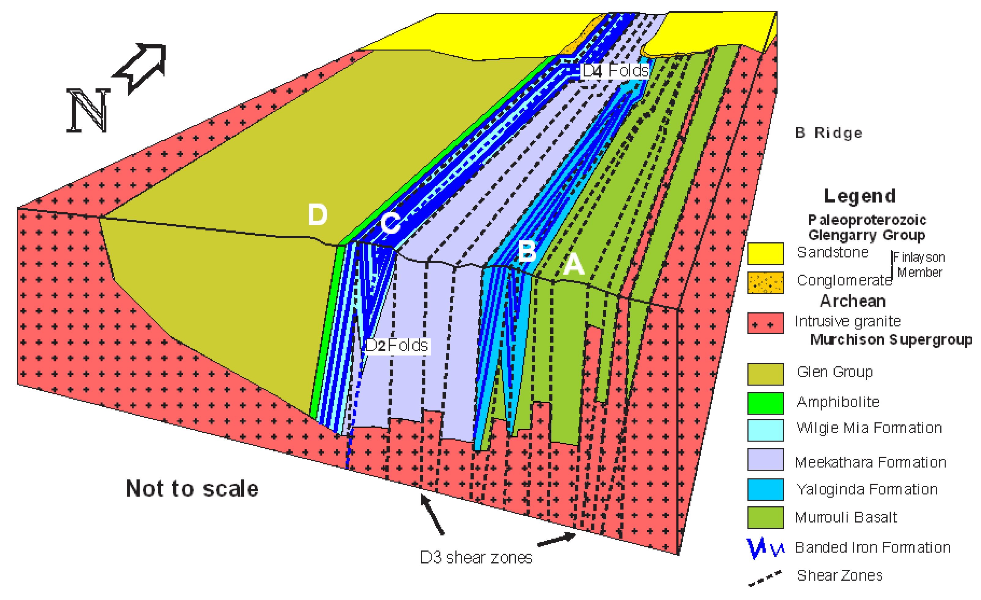
The BIF sequences are tightly folded about sub-vertical northerly trending axial planes with very numerous crosscutting normal faults; however, folding and faulting are rarely visible in the amphibolite sequences. The lower BIF sequence (Yaloginda Formation, B Ridge, (
Figure 3) consists of several discrete thin-bedded BIF and granular iron formation (GIF) units interbedded with mafic amphibolite, whereas the upper unit (Wilgie Mia Formation) outcrops as a ~400 m wide sequence of <200 m wide composite BIF bands with interbedded amphibolite and chlorite schist (C. Ridge,
Figure 3). The Wilgie Mia Formation overlies amphibolite with numerous bands of chlorite schist and minor felsic lenses within the Meekatharra Formation. Siliciclastic sedimentary rocks and mafic lavas of the overlying Glenn Group are poorly exposed and were not examined in detail.
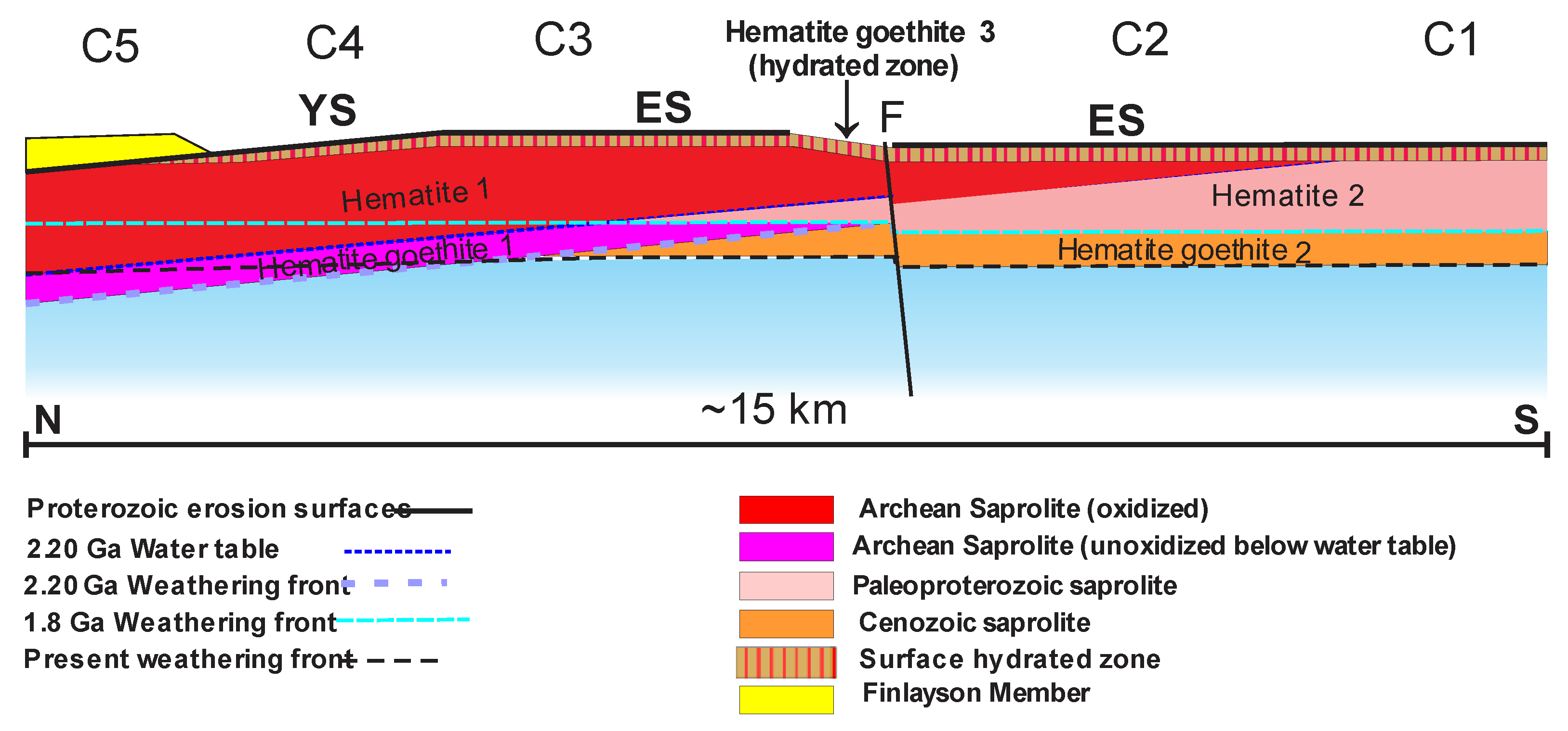
The Archean rocks of the northern JFGB were buried beneath the unmetamorphosed and virtually undeformed epicontinental sedimentary Proterozoic rocks of the Yerrida and Earaheedy Basins until exhumed by Mid-Tertiary to Present erosion. By 2.20 Ga, the northern margin of the Yilgarn Craton was eroded to a deeply weathered arid landscape [
2,
12] similar to the present one, with scattered greenstone belts separated by large areas of granitic rocks. The deep weathering is clearly indicated by the total absence of granitic pebble conglomerate at the base of the Windplain Group although resting unconformably on granite over most of the area. Weathered granitic rocks consist of clay pseudomorphs of feldspar, micas, and amphiboles with unaltered quartz grains and are completely disbursed by marine erosion. Not even core stones were present to produce pebbles indicating a great depth of weathering well below the reach of wave action. Similarly, no amphibolite pebbles occur within the polymict conglomerate associated with the JFGB, which contains only strongly goethitized amphibolite, deeply weathered silicified BIF, and massive hematite pebbles. Further evidence of multiple cycles of weathering shown by the ore deposits at JFGB (
Figure 4) is detailed in [
2,
3].
Part of the northern margin was depressed, forming a sag basin [
13], probably associated with rifting along the northern margin of the Yilgarn Craton, onto which shallow-marine sedimentary facies of the Paleoproterozoic Windplain Group (
Table 1) were deposited [
13]. The marine transgression eroded the smooth wave-cut Yerrida Surface on the deeply weathered Archean rocks [
2]. A second ca 1.95 Ga marine transgression, after the Capricorn Orogeny tilted the craton margin and overlying Windplain Group 12º to the north, produced a new wave-cut erosion surface (labelled the Earaheedy Surface) on a renewed deep weathering profile. An unknown thickness of sediments (Tooloo Group) was then deposited, overstepping the partially eroded Windplain group onto the Archean rocks (
Figure 4). Both the overlying Windplain and Tooloo Group are unmetamorphosed and virtually undeformed. Mid-Cenozoic to Recent erosion has exhumed the Archean rocks of the JFGB, which have been undisturbed for nearly two billion years [
2] with the 2.20 Ga and 1.95 Ga erosion surfaces well preserved on the silicified surfaces of the deeply weathered BIF units (
Figure 3B and
Figure 5). Erosion of the exhumed BIF surfaces is typically restricted to minor gullies with some crumbling along the edges.
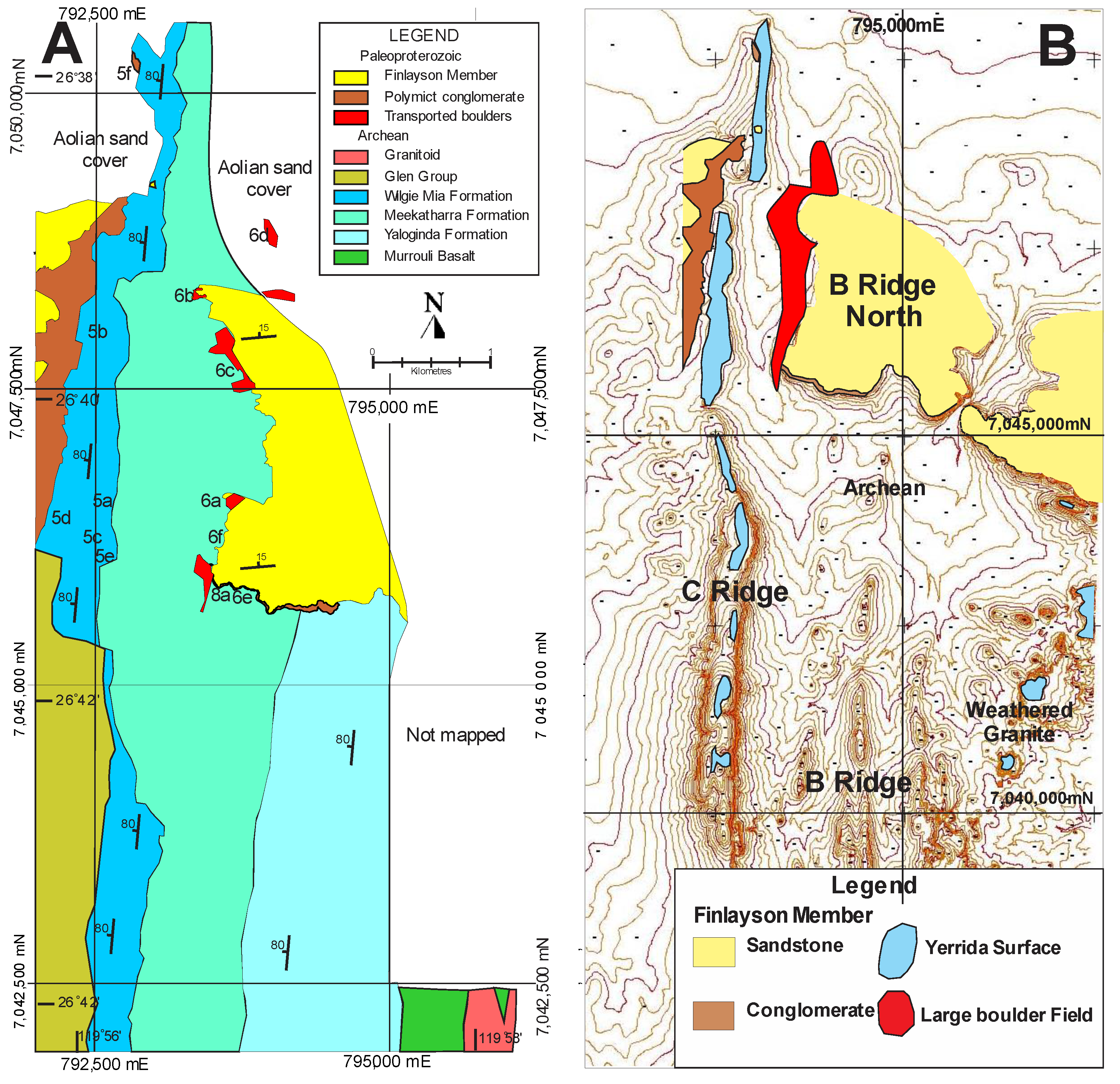
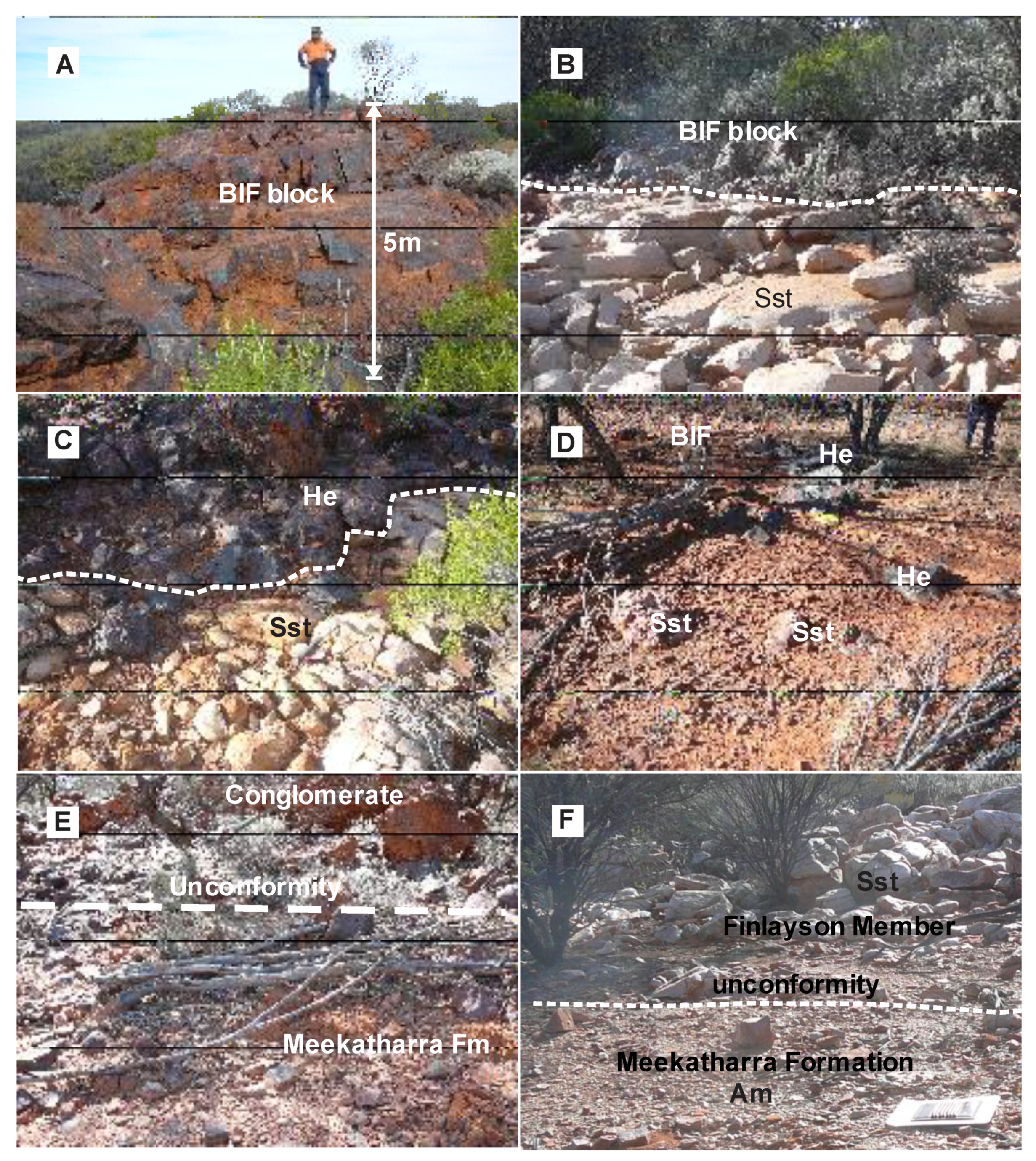
Large blocks and boulders of silicified BIF and massive hematite (up to 40 m × 27 m and 6 m thick;
Table 2) and individually weighing up to 18,000 tonnes (
Figure 6A–D) form a broad band 900 to 1200 m east of the outcrop of the Archean Wilgie Mia Formation (
Figure 3A,B). A polymict conglomerate (
Figure 3 and
Figure 5E) at the base of the Windplain Group consists of locally derived silicified BIF and hematite pebbles with minor goethitized mafic pebbles in a quartz sand matrix and only occurs in the vicinity of the JFGB; elsewhere, the Finlayson Member sandstone rests directly on the unconformity with only the rare occurrence of vein quartz clasts at the base (
Figure 2).
A narrow outcrop of the conglomerate to the west of the Wilgie Mia Formation and other deposits of conglomerate to the east of the transported blocks and boulders are overlain by sandstone of the Finlayson Member. In between these conglomerate deposits, the sandstone rests unconformably on the Archean rocks and the basal conglomerate is almost completely absent from the surface of the BIF and adjacent amphibolites to the east but is found on the eastern side of the boulders on B Ridge North (
Figure 6E). Fine-grained sandstone of the Finlayson Member was then deposited directly on the scoured surface between the large blocks (
Figure 6F) surrounding and overlying the transported blocks and boulders (
Figure 6B–D) passing up into ripple- marked sandstone. Thin lenses of fine BIF-rich conglomerate present near the base of the Finlayson Member to the west of the Wilgie Mia Formation outcrop were not seen in the thicker sandstone horizons on B Ridge. Detailed descriptions of the geology of the JFGB, the unconformities, erosion surfaces, and deep weathering profiles were provided in [
2,
3].
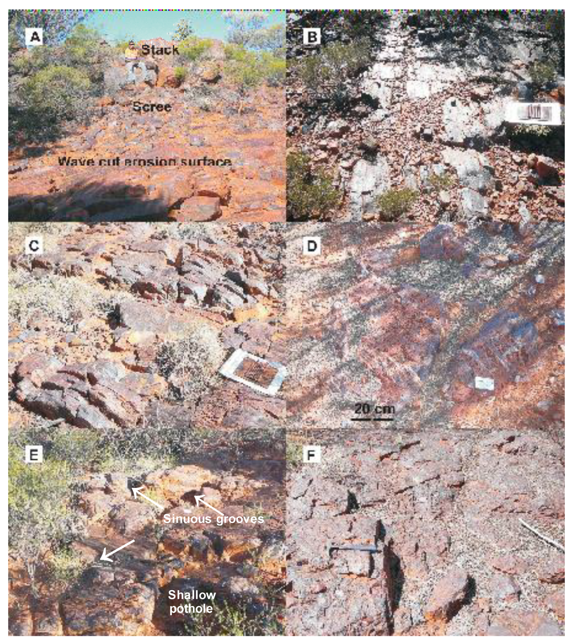
Rare stacks of BIF are preserved on the erosion surface (
Figure 5A), and the erosion-resistant silicified BIF and massive hematite units formed flat-topped reefs (
Figure 5B–D) 1–2 m above the general level of the wave-cut surface on soft clay-rich mafic and ultramafic saprolite. The basal conglomerate of the Finlayson Member is confined to the JFGB and consists of rounded pebbles of BIF, hematite, and goethitized amphibolite in a quartz sand matrix (
Figure 5F) derived by marine erosion of the deeply weathered BIF, iron ore, and amphibolite of the JFGB and is overlain by mature sandstone (
Figure 6B–D). Elsewhere, throughout the northern Yilgarn Province, apart from the rare occurrences of quartz pebble conglomerate [
10], the basal conglomerate is absent and sandstone of the Finlayson Member rests directly on deeply weathered Archean granitoids and greenstones (
Figure 6F) with rare stacks and small pockets of basal conglomerate preserved on the exhumed erosion surface on silicified BIF (
Figure 5A). The deposition of epicontinental sedimentary rocks of the Windplain Group was followed by minor deformation and tilting of the sequence, including the Archean basement, 12° to the north and a prolonged period of deep weathering.
The second marine transgression at ~1.95 Ga followed the deposition and subsequent uplift of the Windplain Group and epeirogenic sedimentary rocks of the Tooloo Group were unconformably deposited on the eroded remnants of Windplain Group and overstepped onto Archean saprolite and unweathered Archean rocks further south. Lascelles [
2] described the very clear contrast between the Proterozoic saprolite and the previously unweathered Archean rocks eroded by the Earaheedy transgression. The wave-cut erosion surfaces formed by both of the marine transgressions (
Figure 2 and
Figure 5A–E) were exhumed by Cenozoic erosion of the overlying undeformed and unmetamorphosed Paleoproterozoic cover. These surfaces are well–preserved on the sub-vertical BIF of the Wilgie Mia Formation and less distinctly on the thinner BIF and massive hematite bands in the Yaloginda Formation and silicified weathered granite outcrops to the east of the JFGB. Deeply weathered mafic and ultramafic rocks of the Meekatharra Formation and Murrouli Basalt have typically been eroded well below the level of the unconformity, except for strongly goethitized outcrops, unless protected by the overlying transported boulders, conglomerate, and sediments of the Windplain Group (B Ridge North;
Figure 2 and
Figure 6E,F).
4. Transported Block and Boulder Deposits
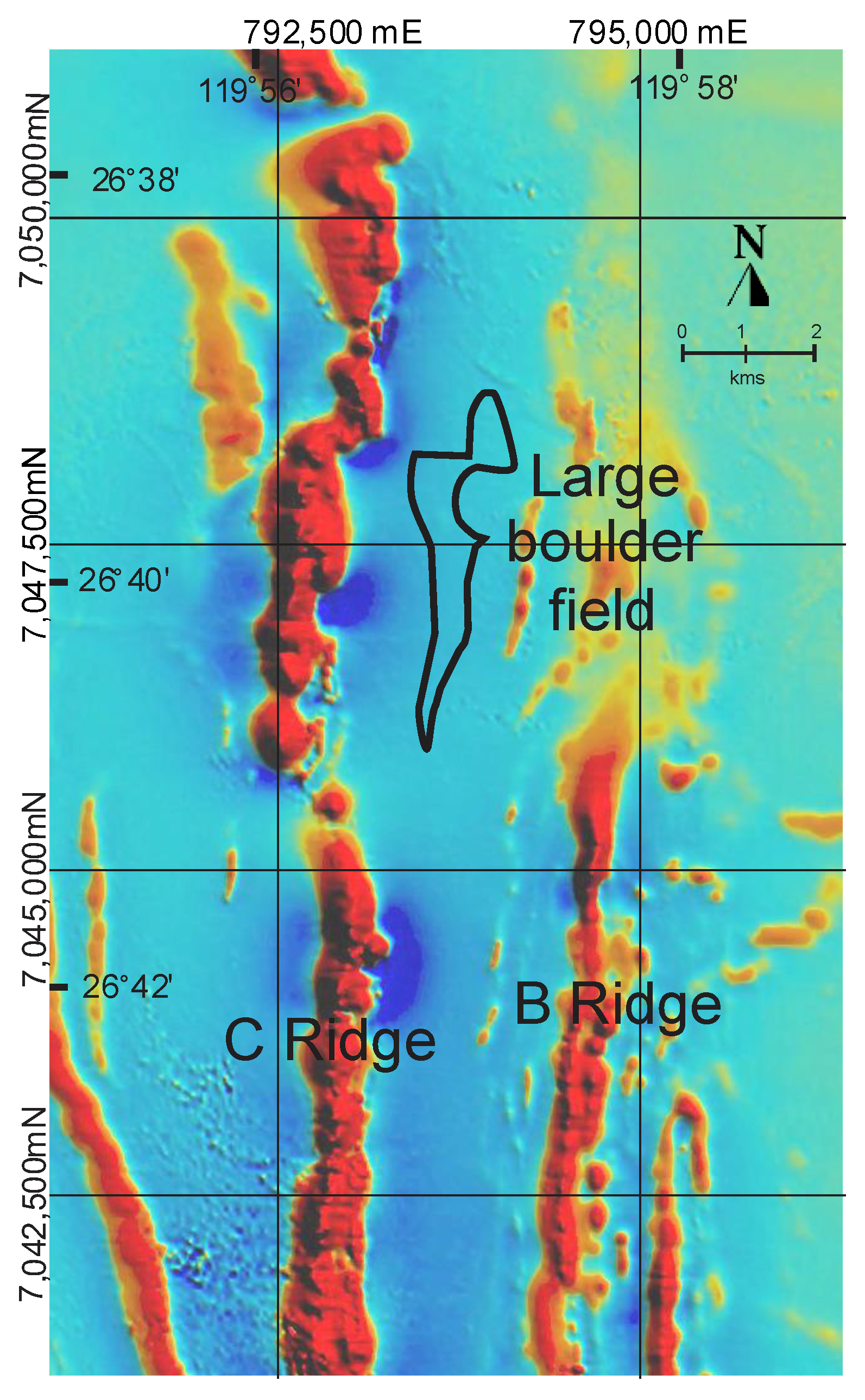
The blocks, boulders, and conglomerate forming a band <3 km wide, 900 to 1200 m east of the Wilgie Mia Formation outcrop, were deposited on the smooth wave-cut erosion surface of deeply weathered mafic and ultramafic amphibolite and schist of the Meekatharra Formation. The bedding strike and dip of the largest blocks is oriented north–south similar, to the outcrops on C Ridge (
Figure 3A) and was first mapped by the author as in situ Wilgie Mia Formation BIF. The smaller boulders have more random orientations, casting doubt on their being in situ. Furthermore, aeromagnetic imagery (
Figure 7) shows no evidence of underlying BIF [
2,
3], and exposures at the base of the blocks indicated that they were isolated from each other and underlain by deeply weathered mafic and ultramafic amphibolite and schist of the Meekatharra Formation. Only a few direct measurements of the block thicknesses could be taken, (
Table 2) as the bases were typically covered by scree, conglomerate or sandstone, but thickness of 5–6 m could be reasonably estimated by the distance from the unconformity to the upper surface of the larger blocks (
Figure 5A).
The upper surface of the blocks was typically flat with maximum relief elevations of ~1 m. Although absent from the erosion surface on C Ridge and for >1 km to the east, a narrow outcrop of polymict conglomerate is well exposed for a distance of ~3 km on weathered amphibolite to the west of the Wilgie Mia Formation BIF (
Figure 3 and
Figure 5E). The polymict conglomerate is also exposed on B Ridge North for ~1 km to the east of a large block of BIF with sporadic exposures associated with BIF and hematite blocks to the north. Between the blocks, the unconformity is overlain by sandstone with no trace of polymict conglomerate at the base. The Finlayson Member disconformably overlies the conglomerate with a small outlier of sandstone resting directly on the BIF at C Ridge.
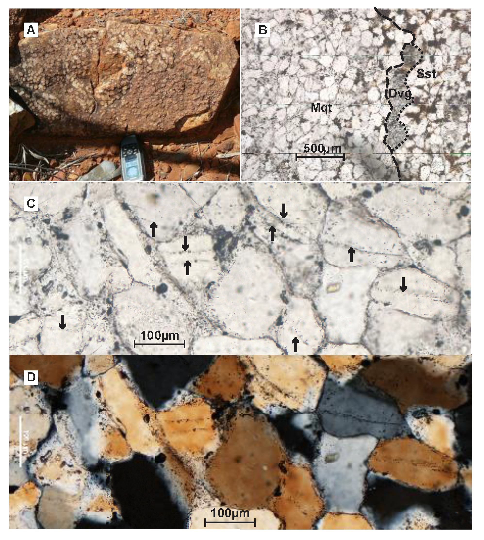
A single layer of slightly irregular spheroids of granulitic metaquartzite was found near the base of the strongly weathered granular quartz sandstone (
Figure 8A) with a few irregular blebs of devitrified glass attached to the spheroids (
Figure 8B). SEM and electron microprobe examination (J. Muhling, pers. comm. 2012) indicated that the glass had a similar composition to the metaquartzite grains. Quartz grains in the metaquartzite show parallel planes of fluid inclusions that are not present in the sandstone grains (
Figure 8C,D). The metaquartzite spheroids appear to be of exotic origin with no known local correlatives. It is suggested that they could possibly be ejecta from an impact crater.
5. Discussion
The large blocks were derived from the Wilgie Mia Formation as none of the BIF units in the Yaloginda Formation are thick enough to provide such large blocks, and several possible scenarios were considered to explain how the BIF and massive hematite blocks were transported at least 900 m to the east from C Ridge (
Figure 2) on the Yerrida Surface. Possible agencies for the transportation of such large blocks range from low-angle thrust faults, mass wasting, debris flows, glacial transport, or tsunami; however, the wave-cut surface is extremely flat, with the exception of rare stack remnants, dipping 12° to the north, and shows very little variation in elevation between the boulder deposits and the erosion surface on C Ridge (
Figure 3B).
The large size of the blocks makes them significantly beyond the capacity of tidal surges and storms to move. Only an extreme flood from an exceptionally large tsunami would have the power to move 18,000-tonne masses over ~1 km. A low-angle thrust is discounted as the stacks rise from the unconformity surface (
Figure 5A), and the boulders and conglomerate rest directly on the unconformity with no intervening breccia or slickensides. A debris flow across the slope could not transport massive material horizontally across such a gently sloping surface. Similarly, mass wasting requires a large difference in altitude for gravity to transport the blocks over one kilometre, which was not present in a low-lying deeply weathered landscape. Numerous boulders lie adjacent to the BIF outcrops on C Ridge at the foot of small cliffs, where they are clearly derived by mass wasting but never extend more than a few metres from the outcrop. At Mt Gibson and Koolyanobbing, for example, sub-vertical BIF outcrops form pronounced ridges with deposits formed by mass wastage extending no more than a few metres from the outcrop. In neither case were BIF boulders found more than 10 m from the outcrop. The stacks show that at least ~3 m was eroded locally by the transgression, but the maximum cannot be much greater or unsilicified saprolite would have been exposed and the surfaces could not have been preserved.
The Hamersley Province has many exposures of shallow dipping (0–40°) BIF forming pronounced cliffs outcropping up to 100 m above adjacent valleys. In most cases, their scree deposits contain numerous large boulders at the top, diminishing in size towards the foot of the slope. Only rarely can large blocks and boulders be carried downslope due to sliding or slumping of scree, due in most cases to increased water saturation. Near Giles point in the Ophthalmia Range, a large 2 m block of BIF had been carried to the foot of the slope ~50 m from the base of the cliff over 30 m above.
At Sliding Mountain in the central part of the Hamersley Ranges and elsewhere, large-scale mass wasting is such that Brockman Formation dipping parallel to the slope has been undercut by fluvial erosion, allowing oversized slabs to break away and slide down towards the valley. This movement is invariably down a steep hillside and does not pass beyond the foot of the slope. The southernmost blocks at JFGB form part of the cuesta on the opposite side of a valley. At Hope Downs, a ravine that was probably the result of tunnel erosion or cavity collapse, cutting through Marra Mamba Iron Formation was blocked by large <4 m boulders of BIF, probably derived from the roof of the cavity and more or less in situ, that the underlying stream was unable to move.
In all these cases, a large difference in elevation is involved, yet transportation is limited to tens of metres. At JFGB, there was little or no difference in elevation of the essentially flat Yerrida Surface, yet the blocks were transported 900 m from their source.
No evidence of glacial deposition such as tillites or other glacial features are known from near the JFGB or elsewhere in the Yilgarn Province in the Paleoproterozoic period. The Meteorite Bore Member (MBM) of the Kungarra Formation lies on the Pilbara Craton that was an unknown distance from the Yilgarn Craton at the time and has been dated at ~2.31 Ga [
14] over 100 Ma earlier. The well-preserved erosion surfaces, boulders, and conglomerate pebbles show no trace of glacial striae. The Yilgarn Craton was a low-lying deeply weathered landscape at 2.20 Ga, clearly shown by the absence of unweathered granite below the unconformity and basal conglomerate. This is evidence of a long period of weathering and stability prior to the transgression. Ice cover would have removed the soft regolith. If the blocks had been moved a mere 1 km to the east by an ice front, then the conglomerate would constitute a moraine left behind as the ice sheet melted and should have covered the whole area and included granite clasts. Since the ice cannot reverse direction, there is no possibility for BIF and hematite pebbles to be deposited to the west of the BIF outcrop, and therefore the polymict conglomerate cannot be part of a moraine.
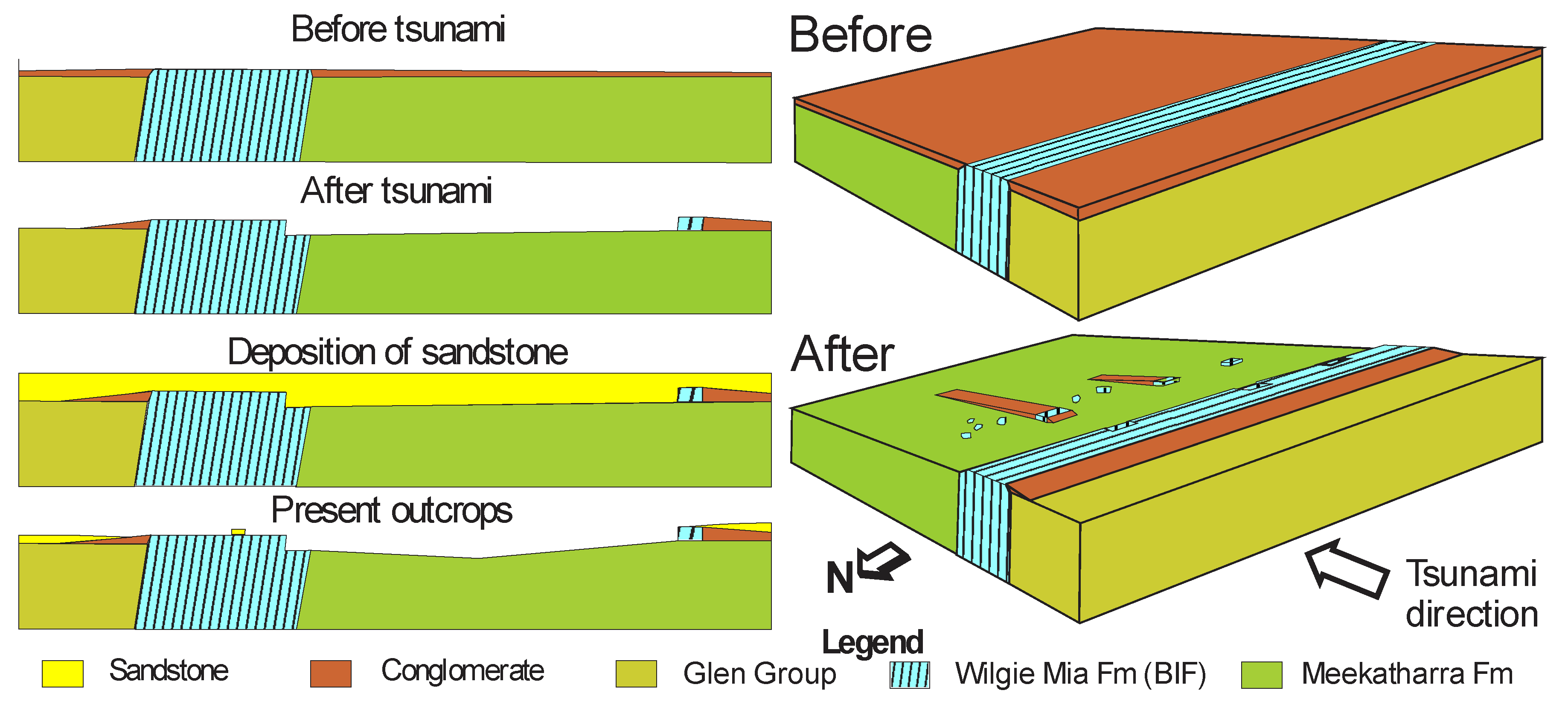
Several lines of evidence support a theory of tsunami deposition. The situation of the blocks, their transportation and deposition, and the scouring of the sea floor are inexplicable by processes other than an extraordinarily large flood during the transgression. The larger slabs show no evidence of rolling or sliding and appear to have been picked up and then dropped in a linear deposit parallel to the source (i.e., in a single action by the onset of the largest bore). They could not be further moved by backwash or subsequent waves, unlike the smaller boulders (
Table 2), which were probably deposited as irregularly oriented clumps [
8]. The basal polymict conglomerate was preserved on the western side of the Wilgie Mia Formation, which acted like a groyne but, apart from rare pockets of polymict conglomerate in potholes on the BIF erosion surface, was completely scoured from the surface of the BIF and the sea floor to the east except where deposited in the lee of the largest blocks (
Figure 9).
The smaller boulders may have been loose debris on the sea floor, and rare stacks may have had fractured tops that were dislodged by the tsunami, but the major source of the giant blocks was probably due to the plucking of joint-bounded blocks from the eastern side of the BIF outcrop (cf. 5). The probable source of the larger slabs can be seen in rectangular notches along the eastern side of the Wilgie Mia Formation outcrop (
Figure 9), and bedrock sculpturing similar to that described by Bryant and Young [
15] is visible on the eastern edge of the wave-cut erosion surface (
Figure 5E), although such sculpturing by tsunami is disputed by later authors. The fine quartz sand that was deposited directly on the wave-cut surface between and over the boulder and conglomerate deposits was probably carried by the tsunami bore and deposited immediately by the flood. The metaquartzite spheroids were apparently also deposited during this period. The proposed tsunami deposits were overlain by the thick ripple-marked sandstone of the Finlayson Member at the base of the Windplain Group. The sandstone with thin lenses of fine-grained BIF conglomerate overlying the conglomerate on the west side of the Wilgie Mia Formation outcrop was probably formed by normal marine processes after the tsunami.
The marine transgression that formed the wave-cut erosion surface is comparable to the Holocene marine transgression that occurred in the English Channel [
16,
17,
18] and the North Sea as sea levels rose following the Pleistocene ice ages. Wave erosion occurred down to a maximum wave depth of ~10 m, forming a wave-cut erosion surface in deeply weathered rocks on which sediments were deposited as the sea level continued to rise and the shoreline moved inland.
The landscape of the Yilgarn Craton at the time of the first marine transgression was also deeply weathered to a depth of <200 m [
2] and generally flat with silicified BIF, silcreted granite, and massive hematite providing minor relief. Naturally, no trace of the shoreline at the time of the tsunami exists as the transgression continued for at least 100 km to the south of the JFGB, and it must be realized that marine transgressions take place over tens to hundreds of thousands of years, depending on the distance covered, the elevation of the eroding landscape and possibly the rate of subsidence of the continent. Neither the blocks nor the conglomerate show any sign of reworking by marine erosion prior to the deposition of the sandstone, of which the lowest layer would have been deposited from the flood. However, no transported boulders occur south of latitude 26°37′33.8″ S (
Figure 3A), suggesting that was the limit of deposition below wave base and deposits further south were reworked by the progressive marine erosion. The northern and eastern limits of the boulder field are obscured by alluvial and aeolian deposits.
5.1. Estimation of the Flood Velocity and Height
Although extreme storm waves have been known to move large boulders (e.g., up to two metres diameter) many tens of meters [
19], they tend to be much less efficient in transporting larger boulders (>2 m) over 100s of meters, for several reasons. Firstly, maximum storm wave heights
Hmax in the deep ocean are limited by their maximum steepness
Hmax/
L~1/7, where
L is the wave length, which tends to limit wind-wave heights to the order of 10 m, even under extreme conditions. Secondly, the short period of storm waves also implies they cannot sustain high velocities in a single direction to move 40 m wide blocks over the distances of ~1000 m that were observed.
Observations of tsunami boulder deposits on land have proven very useful in providing robust estimates of the height and maximum flow velocities associated with modern tsunami waves e.g., [
5,
6], but very few studies of extremely large bores have been done. In the present case of sea floor deposits, it is assumed that the shallow water on the shelf was dragged along by the flood and that the size of the boulders and their displacement from the Wilgie Mia Formation outcrop (
Figure 2 and
Figure 6) can provide a plausible estimate of the magnitude of the flood.
At the time when the event occurred, the unconformity representing the sea floor was already eroded to the wave base by the marine transgression, and the deposits left by the tsunami on the sea floor were undisturbed by further wave action or further erosion of the sea floor, implying the local water depth
h was >10 m. It is most probable that the marine transgression inundated the continent from the north as the Yerrida Basin formed 50–60 km to the northwest [
10], but all traces of coastline, coastal deposits, and onshore deposits were reworked south of latitude 26°37′33.8″ S as the marine transgression progressed.
In addition, high energy flow in tsunamis generally lasts for minutes [
8]. The average flow velocity required to transport the boulders in full-suspension over ~1 km would be of order 10 m s
−1, which is also compatible with the minimum instantaneous flow velocity (~30 m s
−1) required to initiate the transport.
5.2. Speculation on Possible Cause of the Flood
A catastrophic event could produce a tsunami of this magnitude (flood > 40 m in height). It is unlikely that a massive rock slump could generate a flood with the velocity required to transport blocks of over 6000 m
3 in the region of 20,000 tonnes for approximately 1 km, particularly with the low-altitude differential of the extant landscape [
20]. A massive rock slump on the continental slope would only generate low-velocity tsunami waves. An extremely large earthquake on the sea floor with an instant displacement of >30 m could generate waves of sufficient magnitude to displace the blocks, but in neither case would a high-velocity splash be formed to cause a high velocity bore that would be required to scour sand and shingle from the sea floor.
The most probable cause would ultimately be a large oceanic asteroid impact, but a perfunctory search of the Juderina Formation failed to discover any impact spherulites. The layer of granulitic metaquartzite spheroids (
Figure 6A,B) with the devitrified glass blebs and the planar fluid inclusion trails that may possibly be shock-induced (
Figure 6C,D) are suggestive but inconclusive evidence of impact ejecta, and no further evidence was found.
5.3. Oceanic Asteroid Impacts
Four very large asteroids, tens of kilometres in diameter (Vredefort, Sudbury, Shoemaker and Yarrabubba), impacted on land during the Paleoproterozoic era. At present, approximately 71% of the Earth’s surface is covered by oceans, whereas during the Paleoproterozoic, continents were typically smaller with an estimated 90% of the Earth’s surface covered by ocean. Statistically, ten times as many asteroids could have impacted the ocean. Most of the ejecta from an ocean floor crater would either be hurled into space or into the surrounding water column or fall back onto the ocean floor. Unfortunately, since the onset of plate tectonics, oceanic crust is subducted and all the evidence of ancient oceanic impacts is destroyed.
Several authors [
21,
22,
23,
24,
25,
26,
27] have calculated the effects of ocean impacts by small asteroids (300–400 m diameter). These calculations were based largely on the calculations of Van Dorn [
28,
29] with respect to underwater explosions and concluded that they would generate comparatively small tsunami waves. Furthermore, due to the Van Dorn effect, their force would be dissipated before reaching shore. Melosh [
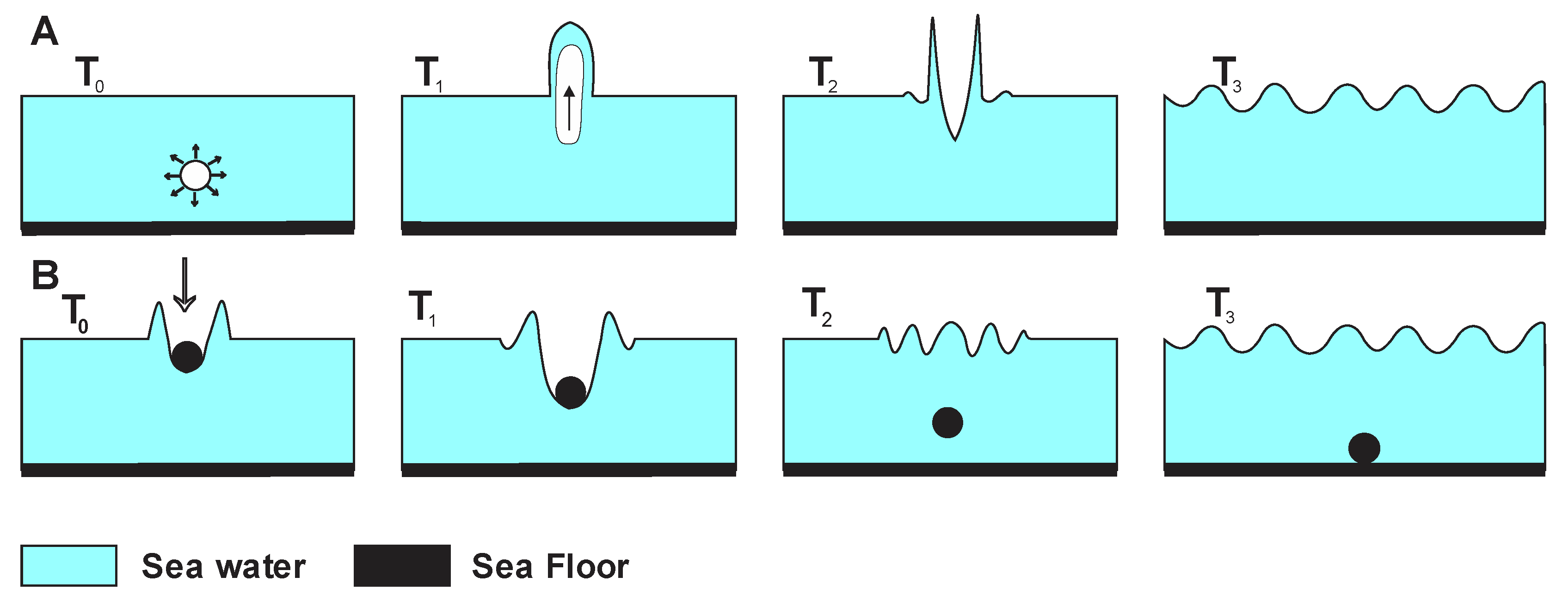
24] claimed that the water displaced by a vertical impact would pile up near the rim of the crater (
Figure 10). All studies have concentrated on the waves generated by the collapse of the ocean cavity caused by the passage of the bolide but have not considered the effect of splash caused by the displacement of water at impact. The Van Dorn [
24] study involved waves generated by underwater explosives, in which the water displaced by the explosion fell back into the cavity, from which it was assumed that the splash generated by asteroid impacts behaved similarly. However, they did not calculate such effects for bolides with a magnitude greater than the depth of the water or non-vertical impacts.
A simple experiment readily shows the contrasting effect of a large asteroid bolide. A 4 cm diameter spheroid (golf ball) dropped from a height of 50 cm into a large tray filled with water 5 cm deep created a largely vertical splash with minor airborne droplets up to 10 cm from the point of impact (
Figure 10B). However, when a 7.5 cm diameter rock was dropped from the same height the effect, was spectacular with a large volume of water ejected as far as ten times the diameter of the rock (
Figure 11).
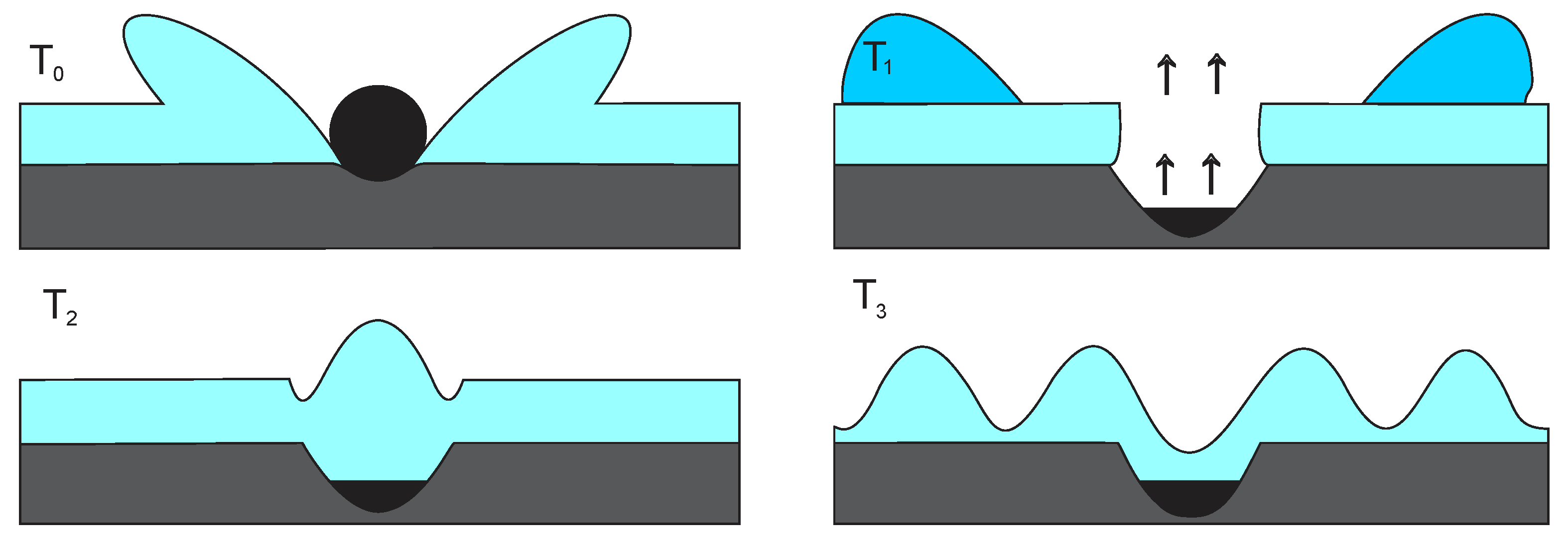
A large asteroid, greater than two kilometres across in diameter assuming ocean depth in the Paleoproterozoic of two kilometres, would initially displace a volume of water (diameter of the asteroid times depth of the ocean) at a velocity approaching the velocity of the asteroid at hundreds of meters per second (the splash). Similarly, a much smaller bolide striking the sea floor on a continental shelf, provided it is greater in diameter than the depth at the point of impact, would also cause a massive displacement of water. In addition to the size of the impactor, the dimensions of the splash would depend on the velocity of the impact and the angle of incidence (
Figure 11). For impacts with a high velocity and high angle of incidence, it is probable that some of the displaced water would be vaporized and thus explode laterally in all directions, creating a crater much greater than the diameter of the impactor (
Figure 10A). By comparison, a low angle of incidence would impel the displaced water in the direction of the impact. The water displaced by the impact would travel away from the impact over the surface of the ocean at hundreds of meters per second—not as a wave but as a moving mass with its own momentum (
Figure 12). Collapse of the cavity in the ocean so produced would then generate waves with a height approaching the depth of the ocean and velocity of hundreds of metres per second.
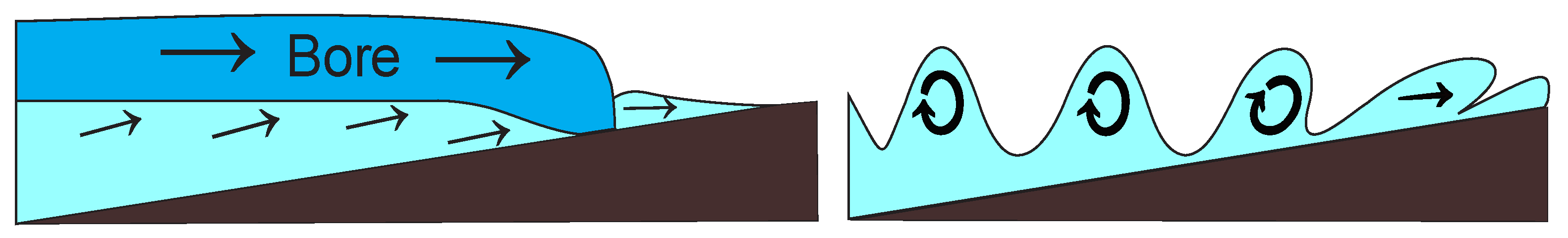
Water travelling over the surface of the ocean as a flood would be slowed by friction with the underlying water, but the momentum would also be transferred and the surface water dragged along until reaching the shelf, where drag would then be caused by contact with the sea floor, inducing the removal of loose sediment from the sea floor. The amount of friction involved is roughly constant for any size of bore, but the larger the bore, the less reduction in velocity over a given distance. Thus, whereas a small impact producing a flood a few meters deep would be rapidly slowed, water and sea floor drag would have minimal effect on floods of 50 m height and above. The flood from the impact of an asteroid kilometres in diameter would also drag the shallow shelf water along, producing a massive flow capable of scouring loose debris from the sea floor and transporting the large blocks as seen at Joyner’s Find. The Van Dorn effect applies to waves that go from the rotary motion of a wave to forward translation after breaking and does not apply to a strong flood of water that is already in forwarding motion (
Figure 12). Contrary to the opinion of [
24], an asteroid greater in diameter than the depth of the ocean, of which >100,000 occur within the asteroid belt, would cause a disastrous flood in addition to severe earthquakes and atmospheric disruption devastating to coastal communities in its path.


